Fundamentals Course. Appalachian Underground Corrosion Short Course West Virginia University Morgantown, West Virginia
|
|
|
- Daisy Peters
- 5 years ago
- Views:
Transcription

1 Fundamentals Course Appalachian Underground Corrosion Short Course West Virginia University Morgantown, West Virginia Copyright 2009
2 APPALACHIAN UNDERGROUND CORROSION SHORT COURSE 2009 FUNDAMENTALS COURSE PERIODS 1 AND 2 - FUNDAMENTALS OF CORROSION MATHEMATICS AND ELECTRICITY PERIOD 3 - FUNDAMENTALS OF CORROSION PERIOD 4 - INTRODUCTION TO CATHODIC PROTECTION PERIOD 5 - PIPELINE ELECTRICAL ISOLATION METHODS PERIOD 6 - FUNDAMENTAL INTRODUCTION TO PIPELINE COATINGS PERIOD 7 - FUNDAMENTALS OF RECTIFIER MONITORING PERIOD 8 - PIPELINE LOCATING PERIOD 9 - POTENTIAL MEASUREMENTS PERIOD 10 - COMMON MISTAKES MADE TAKING CP READINGS May 22, 2009 Revision To submit comments, corrections, etc. for this text, please curriculum@aucsc.com
3 Appalachian Underground Corrosion Short Course - Fundamentals Section Fundamentals of Corrosion Mathematics and Electricity By: Ric Row OVERVIEW Mathematics and the physical sciences can be intimidating. The only way that I know of to overcome this intimidation is through practice. Math is a skill and like any other skill, it must be practiced repeatedly. It is not something that a student will remember completely after they ve listened to the instructor for two hours. It just isn t that simple. What we ll be talking about is not particularly difficult. It just takes time and effort to learn it thoroughly. This brief introduction to Corrosion Mathematics and Electricity will introduce the following topics: Units (and common factors), Ohm s Law, Electrical Circuits and will touch briefly on rectifier efficiency and temperature scale conversion. I have included copies of some of the slides I ve used in the lecture throughout this chapter. This is to help the student follow along. UNITS - COMMON FACTORS We will start with two very simple mathematical concepts. First, if I multiply any number times 1, the original number doesn t change. And if multiplying the number times 1 doesn t change the original number, then I can multiply that number times a string of ones and never change the original number. So far this stuff isn t too hard. One times anything is still anything. Now let s introduce the second concept. Any number divided by itself equals one. The single real number that this does not work for is zero (0). If you are trying to divide any number by zero (in the field of corrosion control), you ve done something wrong. 1-1
4 This second concept demonstrates that anything divided by itself is equal to one. Now here s where we get away from pure math and swerve into the physical world. Instead of using numbers like I ve shown, let s use a physical quantity. Distance is a well understood concept for most people in this class. So the discussion will begin with that familiar parameter. If one person walks 5,280 feet, and another person walks 1 mile, which person walked farther? Neither walked farther, they both walked the same distance, because 1 mile is equal to 5,280 feet. If I can write 1 mile = 5,280 feet, I can also write the following: 1mile [A] 1 mile 5,280 feet = 1 -or- = 1 5,280 feet I can also invert the ratios above and write the following. 5,280 feet [B] 5,280 feet 1 mile = 1 -or- = 1 1mile The terms feet and miles are referred to as units and have similar mathematical properties as pure numbers, which we ll see by way of example. Another term for the ratios as shown above is conversion factor. Now that I ve expressed these ratios in a usable form, this is all that is necessary to convert from miles to feet and from feet to miles. If I wanted to know how many miles were in, say, 15,000 feet, I would multiply the distance in feet times the proper form of the conversion factor. If I use form [A] above, I get the following equation: 1mile 2.84 feet miles 15,000 feet * = = 2. 84miles 5,280 feet feet 1-2
5 The unit of feet appears in both the numerator (top) and denominator (bottom) of the solution. Recalling the second concept discussed, anything divided by itself is equal to one, then the feet cancel (to make a long story short), and we re left with a solution of 2.84 miles. When we re talking about units: feet is the same as foot and miles are the same as mile. More generally the plural unit is the same as the singular unit. So what? We have all we need to convert units. Convert feet to miles. The units must cancel it s your clue feet * (1 mile / 5280 feet) = 2.84 miles ^ If the units don t come out right you did it incorrectly feet * (5280 feet / 1 mile) = 79,200,000 ft-ft/mile ^ Your knowledge of distance tells you that answer looks right. If we had used the inverse of the conversion factor, form [B], then our solution would have looked like this: 15,000 5,280 feet feet * 1mile 79,200,000 feet = mile feet By using form [B] we re left with a very big number (79 million) and an unrecognizable unit of feet*feet per mile. Two clues that something is wrong: huge number, and strange unit. Either one should warn you that you may have an error. The unit of feet failed to cancel each other out, because the conversion factor was in the wrong form for this problem. Form [A] was the correct conversion factor to use when converting feet to miles. If we wanted to convert a distance in miles to feet we would apply the other form [B] of the conversion factor. Given 8.62 miles, find how many feet that is. We set the problem up like the last but we want the unit of miles to cancel so our answer has the units of feet miles * 5,280 feet 1mile = 45,513 miles feet mile = 45,513.6 feet 1-3
6 The unit miles in the numerator cancels with the units of miles in the denominator and we re left with the units of feet. Had we used the wrong conversion factor, our equation would have looked like this miles * 1mile 5,280 feet = miles miles feet The resulting number is WAY too small if we started with miles, and the units don t make sense. These are two clues that the conversion factor is wrong. The concept of distance, as opposed to a more abstract quantity like current density, makes most people comfortable with these manipulations. Another unit system that people are comfortable with is money. Two quick examples with money will illustrate the concepts. Suppose you re cleaning out your car and find $39.70 that you forgot you put there. You drive right down to Charlestown and settle in to your favorite nickel slot machine. You want to know how many turns this windfall will buy? It s a simple conversion US Dollars * 20USNickels 1USDollar = 794 US Nickels If you wanted to know how many quarters it is, use the proper conversion factor US Dollars * 4USQuarters 1USDollar = US Quarters Or 794 US Nickels * 1USQuarter 5USNickels = US Quarters Of course there is no 0.8 quarter so there ll be other coins besides the 158 quarters. The lowest denomination of US currency is the penny, so we ll figure out what is left over after the 158 quarters. 0.8 US Quarters * 25USPennies 1USQuarter = 20 US Pennies The $39.70 that we started with is either 794 nickels or 158 quarters with 20 cents left over. 1-4
 AND how many inches are in a foot (12), then I can make the conversion in one equation. 6.")
7 Up to now we ve been dealing with only one conversion factor at a time. We don t have to. We can string many conversions factors together in one equation. If I want to know how many inches are in miles, I don t need to know how many inches are in a mile. If I know how many feet are in a mile (5280) AND how many inches are in a foot (12), then I can make the conversion in one equation miles * 5,280 feet 1mile * 12inches 1 foot = 407,088 miles feet inches miles feet = 407,088 inches I could even go from miles to millimeters just by knowing how many millimeters are in an inch (25.4). You can see this on a ruler (that has a metric scale opposite the English). If I wanted to convert miles to millimeters, I would do it as follows miles * 5,280 feet 1mile * 12inches 1 foot * 25.4mm 1inch = 10,340,035 mm I could have gotten that answer by multiplying the 407,088 inches by 25.4 to yield 10,340,035 mm. When dealing with abstract quantities ohms, volts, millivolts, amps, milliamps it is easy to get confused. You can t rely on feel or experience when dealing with unfamiliar units. So you must get the conversion factor correct. In the situation of having to convert unfamiliar units, STOP the more complex problem, and do a miles-to-feet conversion or a quarter-to-dime conversion. It will illustrate which unit goes in the numerator (top) and which unit goes in the denominator (bottom). Then apply the concept to the problem you re working. 1-5
8 It may be helpful here to list some common conversions. 1 mile = 5280 feet 1 yard = 3 feet 1 foot = 12 inches 1 inch = 25.4 mm 1 m = 100 cm 1 km = 1000 m Now we ll use the same principles to convert less familiar units. A modern multi-meter displays automatically the units of volts or millivolts depending on the magnitude of the reading. A small voltage reading will be displayed on the millivolt scale. A large voltage reading will be displayed on the volt scale. While this is convenient to the operator, the operator s ability to convert between scales suffers. There are 1,000 milliamps in 1 amp, and 1,000 millivolts in 1 volt. Our conversion factors are as follows: 1000millvolts 1volt = 1 or 1volt 1000millivolts = milliamps 1amp = 1 or 1amp 1000milliamps = 1 Examples: Given 1.71 Amps, convert current to milliamps amps * 1000milliamps 1amp = 1710 milliamps Given 2300 milliamps, convert current to amps milliamps * 1amp 1000milliamps = 2.3 amps. Given 823 millivolts, convert voltage to volts. 823 millivolts * 1volt 1000millivolts = volts 1-6
9 Given 12.5 volts, convert voltage to millivolts volts * 1000millivolts 1volt = 12,500 millivolts ELECTRICAL CIRCUITS Basic circuit analysis requires knowledge of the symbols used to represent the electrical components. The slide below shows the various symbols. OHM s Law describes the relationship between voltage, electrical current and electrical resistance. In its most commonly shown form it is E = i * R or V = I * R In this form, E (or V) is the voltage (or potential) measured across an electrical resistance (R) for a given current flow (i or I). The unit for E is volts. The unit for I is amps. The unit for R is ohms. The symbol for ohm is the Greek letter omega Ω. A common illustration is the triangle which is a device to help solve the equation in terms of all the variables. First the triangle must be drawn as follows. The letters must be in the positions shown. E I R 1-7
10 By covering the variable you would like to determine, the remaining configuration shows the position of the two remaining variables. For instance if we wanted to solve for potential (E) we would cover E and be left with I R on the bottom. Then E = I * R, which is where we started. If we wanted to find current (I) we would cover I and be left with E / R. Therefore according to Ohm s Law, I = E / R. And finally, to find resistance (R), we would cover the R and be left with E / I. Or R = E / I. The three possible arrangements of Ohm s Law are: E = I*R [equation 1] I = E/R [equation 2] R = E/I [equation 3] When using Ohm s Law, it is necessary to convert all units to ohms, amps and volts to avoid any confusion. Milliamps must be converted to amps. Millivolts must be converted to volts. Resistance must be expressed in ohms, not milliohms, kiloohms or megaohms. Failing to use consistent units will result in an error. APPLICATION OF OHM s LAW Given a simple circuit with a voltage source of 1 volt and a resistance of 1000 Ω, find the current flowing through the circuit. The form of Ohm s Law would be [equation 2]. I = 1 volt / 1000 Ω - or - I = amps 1-8
11 1-9
12 We could stop here if circuits only had one resistor in them. Circuits are usually composed of several resistors. Resistors are arranged in series or parallel or some combination of parallel and series configurations. In order to analyze the circuit, the equivalent resistance must be calculated. RESISTORS IN SERIES The voltage drop around a closed circuit must add up to zero. The voltage input from the source will always be exactly equal to the sum of all the voltage drops across the individual resistors. In a series of resistors, the same current flows through all the resistors. Depending on the individual resistances, the voltage drop across the individual resistors is different. This can be used to determine a formula for equivalent resistance for a series of resistors. In the slide shown above, the equivalent circuit is on the left side and the actual circuit is on the right side. On the left, the voltage input from the source is equal to the voltage drop (V eq ) across the equivalent resistance (R eq ). On the right, the voltage input from the source (same as V eq ) is equal to the sum of the voltage drops across resistors R1, R2 and R3. The voltage drop (V eq ) across the equivalent resistance (on the left) is equal to the sum of V1, V2 and V3 on the right. We can write that: V eq = V1 + V2 + V3. Applying Ohm s law (V = IR), we can re-write the above voltage equation as follows: I eq *R eq = (I 1 * R1) + (I 2 * R2) + (I 3 * R3). 1-10
13 Since the two circuits are equivalent, and all the resistors are in series, all the currents (I eq, I 1, I 2, I 3 ) are the same. I * R eq = (I * R1) + (I * R2) + (I * R3) Applying some algebra, we can re-write the equation as: I * R eq = I *( R1 + R2 + R3) Finally, the current (I) cancels out and we re left with the equation for the equivalent resistance of resistors in series: R eq = R1 + R2 + R3 When the resistors are in parallel, the voltage drop across each resistor is the same. The current flowing through each resistor is different (if the resistance is different). We can develop the equivalence equation the same way it was developed for the series resistors. 1-11
14 RESISTORS IN PARALLEL The total current (I tot ) flowing through the equivalent circuit (on the left) is equal to the sum of the currents flowing through each resistor in the parallel circuit. We can write this as follows: I tot = I1 + I2 + I3 Rewriting each term using Ohm s Law (I = V/R), we get: V tot / R eq = V 1 /R1 + V 2 /R2 + V 3 /R3 Recalling that in a parallel circuit, the voltage across each resistance is the same, we can rewrite the above equation as: V/R eq = V/R1 + V/R2 + V/R3 Since all the voltages are the same and in each term of the equation, they cancel. We are left with the following equation: Or 1/R eq = 1/R1 + 1/R2 + 1/R = + + R eq R1 R2 1 R3 A warning about calculations is useful here. In the above equations, unless you are very comfortable with algebra, you should calculate the decimal equivalent of each individual 1-12

15 1/R term first. Then add the decimal equivalents together. Then take the inverse of that number. The order of the mathematical calculations is important. If the order is done incorrectly, the answer will be wrong. The slide here shows this order. The following is an example calculation. 1-13
16 We have been working with three resistors throughout the examples. These equations work with any number of resistors in parallel. COMBINATIONS OF RESISTORS Most circuits are some combination of series and parallel. In order to determine current flow or voltage drop across an individual resistor, the entire circuit will often have to be condensed to one equivalent resistance. The diagram below shows an example of the steps to be taken for a given combination circuit. The solution is not numerical it merely shows the order in which equivalent resistances are determined. 1-14
17 TEMPERATURE CONVERSION There are two common temperature scales used in the United States. The more familiar is the Fahrenheit scale. On the Fahrenheit scale water boils at 212 degrees. Water freezes at 32 and 98.6 is normal human body temperature. On the Celsius (or Centigrade literally 100 divisions ) water boils at 100 degrees and freezes at 0 degrees. The two scales have one common temperature. Minus forty degrees Fahrenheit is the exact same temperature as minus forty degrees on the Celsius scale. It is helpful to know how to convert back and forth between the scales if a temperature correction factor is required. A $10 calculator is all you really need, but in case you forgot it, the two equations to go between the temperature scales follow here. If you re given a temperature in degrees Fahrenheit and need it in degrees Celsius, the equation is: T c = (T f 32) * where: T f is the temperature in Fahrenheit Tc is the temperature in Celsius If given a temperature in degrees Celsius and need it in degrees Fahrenheit, the equation is: T f = (1.8 * T c ) + 32 where: T f is the temperature in Fahrenheit Tc is the temperature in Celsius 1-15
18 RECTIFIER EFFICIENCY We re only going to touch on rectifier efficiency. Let s start with a brief explanation of efficiency in general. Efficiency is the ratio of the desired output to the required input. One of the more common measures of efficiency is the fuel ratings of automobiles. To calculate fuel efficiency you divide the miles driven by the amount of gasoline the engine consumed. This gives the well-known units of miles per gallon (mpg). In this example, miles are the desired output and gallons of gasoline are the required input. Notice the units in the numerator are different from the units in the denominator, which leaves the unit miles/gallon. When the units in the numerator are the same as the units in the denominator, the units cancel and you re left with a solution with no units. In efficiency calculations, the value of the resulting number will always be between 0 and 1. It is often expressed as a percentage. In impressed current cathodic protection, we need DC current to flow onto the pipe, but we must purchase (in most cases) AC power from the local electric utility. The ratio we use is DC power out divided by AC power in. Electrical power is the product of voltage times current. In equation form: P (power) = E (voltage) * i (current) If you use the conventional units of volts and amps, the resulting unit for power will be watts. Efficiency = E( dc)* i( dc) E( ac)* i( ac) The DC power out of the rectifier is easy. You can measure the output DC voltage directly, and with the shunt resistor, you can measure the output DC current. The AC power in is not arrived at quite so easily. The AC voltage is easy enough to measure, but the AC current is not. A clamp on ammeter can be used. The power 1-16
19 equation will not give the exact power value. The reason for this is beyond the scope of this class. It will be close, maybe even close enough. Another way to get AC power is to get the billing data from the electric service provider. To convert from the kwh value on the bill to a value of power requires the following info from the bill: energy used (kwh) and the number of days in the billing period (usually 30). kwh*1000 AC Power = days*24 If a recent electricity bill for a given rectifier was for 554 kwh, for a 29 day billing period, the average AC power to the rectifier would be calculated as follows: 554*1000 ACPower = = 796Watts 29*24 If you had measured a DC output voltage of 50 Volts and an output current of 4.5 Amps, the DC Power would be: DC Power = 50 V * 4.5 amps = 225 Watts Then the efficiency of the rectifier would be: 225Watts Efficiency = 796Watts = = 28.2% Interpretation of rectifier efficiency measurements is beyond the scope of this course. Suffice it to say that a consistently-high efficiency of the rectifier and anode bed is desired. 1-17
20 Fundamentals Course Basic Corrosion Fundamental introduction and theory behind the corrosion process CORROSION THE DETERIORATION OF A MATERIAL, USUALLY A METAL, DUE TO A REACTION WITH ITS ENVIRONMENT OR THE TENDENCY OF A REFINED METAL TO THE TENDENCY OF A REFINED METAL TO RETURN TO ITS NATURAL STATE AS AN ORE 3-1
21 RETURN CIRCUIT CATHODE ANODE DC ELECTROLYTE FUNDAMENTAL CORROSION CELL CORROSION CURRENT RETURN CIRCUIT ANODE CATHODE FUNDAMENTAL CORROSION CELL ON PIPE 3-2
22 TYPES OF CORROSION NATURAL STRAY NATURAL CORROSION CAUSED BY A NATURAL REACTION BETWEEN A METAL AND ITS ENVIRONMENT YOU BURY A PIECE OF METAL AND IT CORRODES HERES WHY 3-3
23 Dissimilar Metal Corrosion Gas and Water Service Lines Steel gas service (Anode) Gas Meter with no or shorted insulation Water Heater Gas main Water main Copper water service (Cathode) Dissimilar Metal Corrosion Copper Service on a Steel Main Copper Service (cathode) e) Steel Main (anode 3-4
24 Dissimilar Metal Corrosion Brass Stop in a Steel Line Steel pipe Brass (cathode) (Anode) Corrosion due to cinders Physical contact between Pipe and Cinders Soil contaminated with Cinders Pipe Wall (Anode) Cinder (Cathode) 3-5
25 Corrosion caused by Dissimilarity of Surface Conditions Threads bright metal (Anode) Pipe (Cathode) Scratches caused by pipe wrench (Anode) New-Old Pipe Corrosion Cell Old Pipe (cathode) New Pipe (anode) Old Pipe (cathode) 3-6
26 Corrosion caused by Dissimilar Soils Cathode Area Anode Area Cathode Area Sandy Loam Clay Sandy Loam Corrosion caused by Mixture of Different Soils Top Soil Clay Shale Ditch Line Mixture of soils Clay 3-7
27 Corrosion caused by Differential Aeration of Soil Aerated Soil Oxygen Available (Cathode) Structure Poor or No Aeration (Anode) Stress Corrosion Lower Stressed Area (Cathode) Higher Stressed Area (Anode) Lower Stressed Area (Cathode) Pipe Coupling 3-8
28 Cast Iron Graphitization Microbiologically Influenced Corrosion (MIC) Two types: Acid Producing Bacteria (APB) Sulfur Reducing Bacteria (SRB) Unique pitting of metal: Step wise pitting Smooth Thumb print pitting Worm hole pitting The bacteria does not eat the pipe, but rather their waste by products, when mixed with water can create acids. Which dissolve the metal. 3-9
29 Microbiologically Influenced Corrosion (MIC) Can occur internally and externally. Can be mitigated internally, by use of chemical inhibitors, added to the gas stream, or by removing the water from the system. Can be mitigated externally by certain types of coatings, or with enhanced cathodic protection, pipe surface potentials over 1.5 volts. Review the types of corrosion Naturally Occurring Corrosion Dissimilar metals Dissimilar surface Dissimilar Soils Differential Aeration Cinders Stress Graphitization Microbiological Influenced Corrosion 3-10
30 Stray Current Corrosion Caused by discharge of man-made made current. DC (direct current) AC (alternating current) Telluric Currents Sometimes called electrolysis Stray Current Corrosion Alternating current, is mainly a safety issue. AC can be induced from overhead high h voltage power lines. A measured voltage over 15 volts AC, must be mitigated. Can be measured by setting meter on AC volts, and taking a pipe to soil reading. Direct current, is a large concern to the corrosion person. Due to the fact that 1 ampere leaving a steel structure, removes 20 pounds of iron per year. DC stray currents can be a rather large amount. There is two types of DC stray current, static or steady state and dynamic or fluctuating current. Example: 2 amps per year 2amps X 20 pounds = 40 pounds lost Times 3 years = 120 pounds of lost iron 6 inch pipe weights pounds per foot 3-11

31 Stray Current from DC Transit System Dynamic Stray Current Stray Current from Underground Mining Operation Dynamic Stray Current 3-12
32 Stray Current from Impressed Current System Static Stray Current Stray Current from High Voltage DC Transmission Lines Static Stray Current + - SOURCE LOAD - + _ + SOURCE LOAD 3-13
33 Types of Corrosion Stray Current Corrosion Electrified railroads/transit systems Underground mine railroads Impressed Current Cathodic Protection High Voltage DC Transmission Lines 1 Ampere removes 20 pounds of iron per year, from structure Factors Affecting the Rate of Corrosion Soil Resistivity Anode/Cathode Relationship Potential Difference between Anode/Cathode Polarization 3-14
34 Soil Resistivity Below 500 ohm-cm Very Corrosive 500 to 1000 ohm-cm Corrosive 1000 to 2000 ohm-cm Moderate Corrosive 2000 to 10,000 ohm-cm Mildly corrosive 10,000 ohm-cm and above Progressively less Corrosive Anode to Cathode Ratio Large anode to small cathode, the rate of corrosion at the anode is must less severe. Because there is a larger surface area from which the current will discharge. Large cathode to small anode, the rate of corrosion at the Anode is much more severe. Because the area at which to Discharge current is concentrated, to a smaller area. 3-15
35 Potential Difference between the Anode and Cathode Practical Galvanic Series Active End Material Potential* High Potential Magnesium Magnesium Alloy Zinc Aluminum Alloy Clean Carbon Steel to 0.80 Rusted Carbon Steel to 0.50 Cast/Ductile Steel Lead Steel in Concrete Copper High Silicon Iron Carbon, Graphite Passive or Noble End * Potentials with respect to saturated Cu-CuSO 4 Electrode Polarization High Potential Magnesium P/S Volts Clean Carbon Steel P/S to 0.80 Volts Anode Cathode 0 Time 3-16
36 The End Have a great week at Appalachian Underground Corrosion Short Course John Otto Equitable Gas Company 4 South 9 Th Street Pittsburgh, PA jotto@eqt.com Phone: Rules to remember in corrosion work: 1. The hardest problem to solve is the one that doesn t exist. 2. Don t take for granted the work done before you, was correct. 3. Never criticize the work done before you came aboard. (They had a reason, right or wrong.) 4. Always start with the simplest fix. 5. If one thing doesn t work try something else. 6. Don t assume the way you were taught is the right way. 7. Whatever works for you is the way you should work. (Note: I didn t say it s the best way.) 8. Don t dismiss a fresh idea. 9. Use common sense. N.A.C.E. Certified Corrosion Technician Bertman J. Smith 3-17
37 Introduction to Cathodic Protection Thomas B. Williams, Jr. New England CP, Inc. 1 Much of the material in this class comes from the Basic Course Chapter 3 Corrosion Control Methods 2 4-1
38 Corrosion Control Methods For Natural or Galvanic Corrosion Control: Coatings Cathodic Protection Isolating Joints For Stray Current Corrosion Control: Coatings Cathodic Protection Isolating Joints Drainage Bonds 3 The 4 Parts of a Corrosion Cell Anode Cathode Electrolyte Return Circuit If we are missing any one of these four things we will not have a corrosion cell. Keep this in mind because we can use this to our advantage
39 The Fundamental Corrosion Cell There are 4 parts to a corrosion cell: 5 The Fundamental Corrosion Cell Current flows through the electrolyte from the anode to the cathode. It returns to the anode through the return circuit
40 The Fundamental Corrosion Cell Corrosion occurs wherever current leaves the metal and enters the soil (electrolyte). The point where current leaves the metal is called the anode. Corrosion occurs at the anode. 7 The Fundamental Corrosion Cell Current is picked up at the cathode. No corrosion occurs here. The cathode is protected against corrosion. This is the basis of cathodic protection. A hydrogen film builds up at the cathode. The hydrogen film is referred to as polarization
41 The Fundamental Corrosion Cell The flow of current is caused by a potential (voltage) difference between the anode and the cathode. 9 The Fundamental Corrosion Cell Current flows through the electrolyte from the anode to the cathode. It returns to the anode through the return circuit. Corrosion occurs wherever current leaves the metal and enters the soil (electrolyte). The point where current leaves the metal is called the anode. Corrosion occurs at the anode. Current is picked up at the cathode. No corrosion occurs here. The cathode is protected against corrosion. This is the basis of cathodic protection. A hydrogen film builds up at the cathode. The hydrogen film is referred to as polarization. The flow of current is caused by a potential (voltage) difference between the anode and the cathode. If we do not have any one of these four things we will not have a corrosion cell
42 Coatings are the first line of defense in corrosion control We don t need cathodic protection if the metal is not in contact with the electrolyte. We have eliminated one part of the corrosion cell, the electrolyte. Unfortunately, there is no such thing as a perfect coating. The better the coating, the less cathodic protection we need. We only need to protect the bare areas. The better the coating, the less stray current is picked up on our structure. At stray current discharge areas the damage is concentrated at coating holidays which can result in rapid penetration. 11 Factors that prevent applying and keeping a perfect coating: Undetected handling damage during construction. Detected handling damage during construction that nobody bothered to repair. Stones or debris in backfill that force their way through the coating. Soil movement or structure movement with pressure changes (pipelines). Tree roots working through coating. Excavations by others which expose the structure and damage the coating with excavation equipment. Aka Third Party Damage
43 The Purpose of Isolating Fittings To separate dissimilar metals. To confine cathodic protection current to a structure (or portion of a structure) to be cathodically protected. To confine and reduce the effect of stray current to a manageable proportions (where applicable). 13 Theory of Cathodic Protection Anodes Corrode Cathodes do not corrode. If we make the entire surface of our pipe a cathode there will be no corrosion. Hence the name cathodic protection for this method of corrosion control. Direct current is forced to flow into the earth through a ground connection outside the structure and then through the earth to the structure to be protected. The amount of current forced to flow onto the structure is adjusted to a level which will nullify current discharge in anodic areas and result in net current collection in the areas
44 15 We have achieved cathodic protection when: We have net current flow onto our structure and we have caused a cathodic reaction to occur. In soil this cathodic reaction is typically the formation of a hydrogen film also know as polarization. We can determine if we have achieved cathodic protection by measuring the structure-to-electrolyte voltage. If the structure-to-electrolyte voltage meets a criterion we have achieved cathodic protection. The most common criterion for steel is volts to a saturated copper/copper sulfate reference electrode
45 Cathodic Protection Current Requirement The total amount of current need to cathodically protect a structure. Primarily related to the amount of bare metal that our structure has in contact with the electrolyte. Short, well coated structures have a low current requirement. Long, poorly coated structures have a high current requirement. 17 Two methods of cathodic protection: Galvanic anode or sacrificial anode cathodic protection. Sometimes referred to as a passive system. Impressed current cathodic protection. Sometimes referred to as an active system
46
47 Advantages of Galvanic Anode Cathodic Protection They are self-powered. No dependence on outside sources of power. Low maintenance requirements. Minimum probability of stray current interference on other underground structures. 21 Disadvantages of Galvanic Anode Cathodic Protection Low driving voltage. Relatively l low current output t capacity
48 Ohm s Law: E = IR I = E R R = E I 23 Common Galvanic Anode Materials Magnesium. High potential magnesium anodes have a potential of volts to CSE. Other alloys are around volts to CSE. Most common anode for use in soil. A 17# high potential magnesium anode has a life of approximately 1 amp-year. Zinc. Typically -1.1 volts to CSE. Significantly less driving voltage than magnesium. Used in low resistivity soil and sea water. Also used for AC mitigation. ii i Aluminum. Typically to volts to CSE. Most commonly used in sea water
49 Magnesium and zinc anodes for use in soil are commonly packaged with a prepared backfill consisting of: 75% Hydrated Gypsum (CaSO 4. 2H 2 0) 20% Bentonite Clay 5% Sodium Sulfate 25 The purpose of the prepared backfill is (the short answer): They work better. They work better because they put out more current and last longer if installed in prepared backfill
50 The purpose of the prepared backfill is (the long answer): It increases the effective surface area which lowers the anode to earth contact resistance. The bentonite clay absorbs and retains moisture. The gypsum provides a uniform, low resistance environment. The sodium sulfate (a depolarizing agent) minimizes pitting attack and oxide film formation on the anode. It provides uniform environment directly in contact with anode to assure even consumption
51 Advantages of Impressed Current Cathodic Protection A wide range of DC voltage and current output capacities. This provides great flexibility in system design. Single installations which will protect much larger structures (or portions of structures) than is usually possible with single galvanic anode installations. 29 Ohm s Law: E = IR I = E R R = E I
52 Disadvantages of Impressed Current Cathodic Protection Greater maintenance requirements than for galvanic anode installations. Dependence on availability of a dependable power supply or fuel supply. Continuing cost of energy where AC power or a fuel supply is required. Greater possibility of stray current interference on other underground structures than is the case with galvanic anode installations. 31 Common Impressed Current Anode Materials High silicon cast iron Graphite Mixed metal oxide (MMO) Platinum Scrap steel abandoned structures
53 Other Impressed Current Anode Materials Aluminum Lead Silver Magnetite Polymer conductive 33 Factors is Choosing Common Impressed Current Anode Materials Cost Life Size Ease of construction Compatibility with environmental conditions Historical performance what you have used in the past that works for you
54 Impressed current anodes for use in soil are commonly placed in a prepared backfill. Carbonaceous backfill aka coke breeze. Impressed current anodes can be purchased prepackaged with prepared backfill or it can be placed around anode during construction. The backfill lowers the effective resistance to earth of the anode by increasing its size. The backfill also increase the life of the anodes. 35 Impressed Current Cables and Splices Since the cable on the positive side of the rectifier becomes an anode, it is critical that there be no exposed conductor in the electrolyte or it will corrode quickly and the system will fail. There must be a high quality connection between the anode lead wire and the anode. High quality cable insulation must be used for the anode lead wires and anode header cables. Most commonly this is HMWPE insulation. The anode lead wires are typically spliced to the anode header cable with split-bolt connectors, crimp connectors or exothermic welds. The splices are typically covered with taping systems, epoxy kits or shrink sleeves
55 Impressed Current Cables and Splices (cont) The cable on the negative side of the rectifier is cathodically protected so the cable integrity is less important. Galvanic anode cables get protected by the anode
56 ELECTRICAL ISOLATION CLASS PERIOD 5 Art Birx ISOLATORS Isolators electrically isolate undesirable metal structures from the pipeline that is cathodically protected. Isolators work by eliminating the metallic path from the corrosion cell. 5-1
57 ISOLATORS (cont) Isolators are used but not limited to the following uses: Separate foreign metal structures from protected pipelines Separates different types metals from each other Separates coated lines from bare lines Separates C/P lines from unprotected lines Electrically isolates pipes into manageable sections DIELECTRICAL ISOLATION Primary Function (WHY?) Method of Corrosion Control - To stop the flow of CP current. - To limit the amount of current needed. - to prevent a corrosion cell. Inserted in pipelines and structures to BLOCK the flow of electrical current. 5-2
58 Failure to Provide Dielectric Isolation Severe corrosion can take place. New pipelines would become anodic in connection to the existing bare or poorly coated pipelines. Nonisolated sections of coated and bare piping would allow the potentials to fall below cathodic protection criteria. Failure to Provide Dielectric Isolation (Cont.) Current requirements would increase in order to protect the poorly coated or bare pipe not isolated from the coated piping. Cost of cathodic protection will increase. Corrosive environments can impact the pipeline above (Atmospheric Corrosion) and pipe below ground. 5-3
59 Dielectric Isolation Materials Weld-in isolator Isolating compression couplings Isolating bolted couplings Fiber board gaskets Isolating unions Plastic Pipe Isolating meter swivels Dielectric Coatings Isolation flanges Dielectric Isolation Types Coatings isolate the surrounding environment from the structure, this prevents the electrolyte from coming in contact with the pipeline above and below ground. -Coatings are our number one defense against corrosion on pipelines. 5-4
60 Dielectric Isolation Types (Cont) -Coatings can vary on dielectric strengths, in most cases based on mil thickness and type of materials. - Coatings keep the current on the pipeline. Current leaving the pipeline results in corrosion -Coatings reduce the amount of holidays on a pipeline, and lessen the amount of protective current required. This lowers the cost of materials. Dielectric Isolation Coating Materials Types of coatings used - Liquid Epoxy two part/applied resin and harder, one coat estimate of 20 mils. - Extruded Coatings high density polyethylene with an under coat of mastic approx. 60 mils thickness. - Asphalt Based Mastics cold applied with brush to desired thickness 5-5
61 Dielectric Isolation Coating Materials (Cont.) - Fusion Bonded Epoxy thin film coating, preheated to 400 to 500 F, with applied resin 10 to 18 mils pending customer s design requirements - Cold Applied Tapes plastic film with butyl rubber backing 15 to 35 mils. - Cold Applied Waxes grease type materials, blend of petroleum wax 20 to 30 mils. Dielectric Isolation Devises Meter Isolation & Above Ground Installations Meter Swivels - Installed at meter, isolates customer from pp pipeline - Should be installed on outlet of meter 5-6
 Isolating Unions - Used on above ground")

62 Dielectric Isolation Devises Meter Isolation & Above Ground Installations ( Cont) Isolating Unions - Used on above ground metering & regulation stations to isolate piping - Usually installed on threaded pipe - Not recommended for below ground installation Isolating Union 5-7
63 Dielectric Isolation Devises Plastic Pipe - More economical to use versus weld-end end fittings or flanges - Recommended installing a minimum of 5 ft. of plastic pipe when isolating from steel pipe - Very high dielectric properties - No chance of failure do to shorting Dielectric Isolation Devises Weld-end end Isolator - Can only be installed by qualified welder -Not most economical isolation device to install - Can fail due to soil stress or shifting 5-8

64 Dielectric Isolation Devises Isolating Flange Kit - Components are non-conductive and provide isolation of pipes and fittings connected by flanges - Flange kits consist of: Nonconductive gasket Isolation sleeves Nonconductive washers Weld-End Flange Isolator 5-9
65 Weld-End Flange Isolator Side-View Dielectric Isolation Devises Isolation Compression Couplings - For low to medium pressure pipelines - For pipe up to 2 in diameter -Non-conductive interior components - Some devises prone to leakage - Can fail due to soil stress or movement - Less expensive than other alternatives 5-10


66 Isolating Compression Coupling Dielectric Isolation Devises Isolating Bolted Couplings - For pipelines 2 & larger in diameter -Non-conductive interior components - Can fail due to soil stress or movement - Less expensive than other alternatives 5-11
 on the meter.")

67 Isolating Bolted Coupler Testing Isolators Before installation check all isolators for electrical leakage. The resistance should be OL (over limit) on the meter. Test all isolators after installation before backfilling do not use a ohm meter after the isolator has been installed. Take pipe/soil potential reading on both sides of the isolator keeping the half cell in the same place. If the two readings are not different then the isolator may be shorted. 5-12


68 Gas Electronics Model 601 Isolation Checker Dielectric Isolation Precautions If the isolator is installed near high voltage AC lines or is in close proximity to electrical towers, precautions should be taken to prevent risks to personnel and damage from lightning strikes and stray AC currents. - Methods commonly used: Zinc ribbon Magnesium anodes :To provide a low resistance grounding system 5-13
69 Dielectric Isolation Precautions DOT subpart I, : If installation of the isolator is inside of a building that may have a combustible atmosphere, precautions must be taken to prevent arcing across the isolator. - Methods commonly used: A zinc grounding cell Dielectric Isolation Protection DOT Subpart I, : All isolated metallic fittings shall be coated and cathodically protected. Improper installation and application practices are the primary reasons for failure of isolators! 5-14
70 Pipeline Coatings 2005 AUCSC Fundamentals Session Jeff Didas Colonial Pipeline Company Richmond, VA Remember This! Coatings are the #1 defense against corrosion. This is true for underground, transition and above ground service. 6-1
71 Coating Types Underground buried or immersion service Transition area coatings Atmospheric coatings Underground Pipeline Coatings Mill or Plant Applied Field Applied Line Coatings Repair Coatings Coating Discussion i Coating Cost Coating Quality 6-2
72 Mill or Plant Applied Most economical method to apply coatings Highest level of quality and quality control Plant/Mill conditions allow use of higher performing coatings Normally, high quality storage, handling and shipping Normally allows for some coated pipe storage Field Applied Costly method either over the ditch or in the ditch Hard to manage quality control due to environmental conditions Normally lower performing coatings Newer field coatings do allow higher productivity 6-3
73 Coal Tar Enamel Line Coatings Asphalt Enamel Extruded Polyethylene Fusion Bonded Epoxy Somastic Pritec Liquid Epoxy 3 Layer Tapes Wax Shrink Sleeves Two - Part Epoxy Mastic Misc. Repair Coatings 6-4
74 Coatings Discussion Most important component of a pipeline High quality holiday free coating requires almost no cathodic protection current Coatings need to be specified Coatings need to be tested Every coating has a use, but most coatings are used improperly follow procedures Cost of material Cost of application Cost to repair Handling Expected life Dielectric strength Coating Cost 6-5
75 Coating Quality Quality determines price Quality is normally dependent upon surface preparation & application methods Quality is assured with competent inspection Quality is determined by good procedures and good specifications Transition Area Coatings Used where piping transitions from buried service to atmospheric service Used to protect from mechanical damage freeze/thaw cycle, weed whackers, gravel, etc. Used to protect buried service coatings from Ultraviolet light when used above ground 6-6

76 Atmospheric Coatings Various types, quality and expected life Primary purpose is corrosion prevention, secondary purpose is appearance Problem areas, flanges, nuts, bolts, hold down clamps, p, high temperature service, beneath insulation, through walls/foundations, etc. 6-7


77 6-8


78 6-9


79 6-10


80 6-11
81 Perfect Coating Ease of Application - A monkey can put it on with a mop on any surface or from above ground. Cost Effective - Cost $1.00/Gallon or less! Environmentally Safe and Friendly OK to Drink it. Performance - Lasts forever. In Reality a Perfect Coating Requires a quality standard Requires a quality specification Requires a quality coating mill Requires a quality material or materials Requires a quality inspector or inspectors 6-12


82 6-13


83 6-14


84 6-15


85 6-16


86 6-17


87 6-18


88 6-19


89 6-20


90 6-21


91 6-22


92 6-23


93 6-24


94 6-25


95 6-26


96 6-27


97 6-28


98 6-29


99 6-30


100 6-31


101 6-32


102 6-33


103 6-34


104 6-35


105 6-36


106 6-37


107 6-38


108 6-39


109 6-40


110 6-41


111 6-42


112 6-43


113 6-44


114 6-45


115 6-46


116 6-47
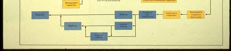
117 Line Pipe Coating Process INTRODUCTION This slideshow steps you through the process of Mill-Applied external thin film (FBE) coating. The guideline for this process is set forth in NACE Specification RP


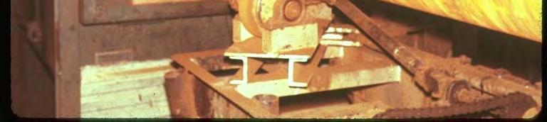
118 The pipe enters the mill and is ready for the abrasive blasting procedure. The pipe enters the pre-heat oven where its temperature is raised to approximately 130 degrees. It then enters the abrasive blasting booth. 6-49


119 The pipe exits the blasting booth with a near-white surface finish and the required anchor profile. At this stage, the blasted pipe surface is checked for raised slivers, scabs, laminations, or bristles which are removed by file or abrasive sanders. A coupler is then inserted into the end of each joint of pipe. 6-50


120 The coupler is used to connect and seal two joints of pipe together, so one pushes the other through the rest of the process. Two pipe joints joined with coupler. 6-51


121 The pipe then enters an acid bath to remove surface contaminants. After the acid bath and rinse, the pipe enters a series of ovens that raise the temperature of the pipe to approximately 475 degrees before application of the coating. 6-52


122 Pipe entering last oven before coating. The joint between pipes is covered, so that the ends of each joint are left free of coating. This is done to allow welding in the field. 6-53


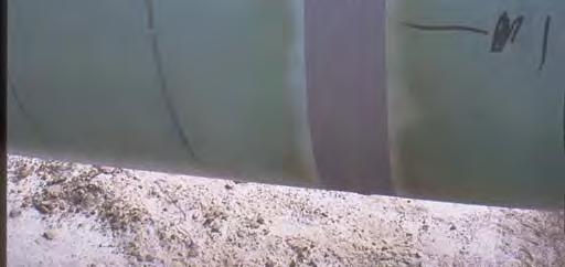
123 The pipe exits the coating booth where jets have applied a coating to the hot pipe with an average coating thickness of 15 mils. The tape around the joint is now removed and pipe continues to the quenching chamber. 6-54


124 In the next step of this process, the pipe enters a quenching chamber and is water cooled to around 250 degrees. Pipe coming out of quenching chamber. 6-55


125 Stencil being added to pipe stating the company name, API information and size and wall thickness of pipe. Company Inspector verifying that the coating thickness is acceptable. 6-56


126 Ropes are put around pipe to keep joints of pipe separated and to prevent coating damage. A 2,000 volt, nonpulsating, low ripple DC dry-type holiday detector is then used to detect any holidays that may exist in the coating. 6-57


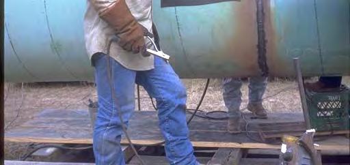
127 Repair of a pinhole size holiday in the coating. Patching with these touch up sticks is only allowed in the mill while the pipe is still hot. Preheating the pipe properly is the limiting factor for field application. Holiday repair using touch-up sticks. 6-58


128 Each pipe is measured and given a number. The pipe is then carried into the yard. The forklift has protective padding on the jaws. 6-59


129 The pipe is stacked with padded boards between them to prevent damage to the coating. The joints of pipe are unloaded on to the padded boards and the ropes separate the joints and protect them from damage when striking other pipes. 6-60
130 The End! Questions? 6-61
131 Rectifier Monitoring Fundamentals Course Morgantown WV Instructor: Greg Alexander Topics for Rectifier Presentation Safety number one! Purpose of a Rectifier Rectifier Components Monitoring Requirements Monitoring Rectifiers 7-1

132 Typical Rectifiers Safety Electricity It Can Kill Rectifiers 120 Volts and up! Critters Reasons for Accidents? Tired In a Hurry Distracted Complacent Angry 7-2


133 Is Electricity Present? Common methods of testing for AC Back of the Hand Issues with this method? Tic Tracer correct voltage range? Features: Voltbeat technology and continuous self-test - so you always know it's working Upon detection, tip glows and beeper sounds CAT IV 1000 V for added protection Expanded range: 90 V to 1000 V AC 20 V to 90 V AC control circuit model also available Rectifiers Contact points! 7-3
134 What does a Rectifier Do? Converts Alternating Current (AC) to Direct Current (DC) Next Slide shows sine wave Provides Cathodic Protection current Basic Electric -AC 120VAC + 0 Half Cycle Peak of positive side of cycle. AC - alternating current will reverse in polarity times per second. A full cycle is considered one hertz. Typical AC has 60 hz per second. Half Cycle 0 Peak of negative side of cycle SINE WAVE 120VAC - 7-4


135 Basic Electric - Rectifying AC AC Positive Cycle Negative Cycle DC Header Cables Negative cable connected to the structure Positive cable hooked to the groundbed What happens if the cables are reversed? 7-5

136 Typical Impressed Current System Basic Components of a Rectifier Circuit it Breaker Transformer Rectifying Elements Fuses Accessory Equipment 7-6


137 Standard Rectifier Unit Standard Rectifier Circuit Breaker Output Fuse Tap Setting Controls Dual Meter - Amps and Volts Meter Switch Rectifier Output Terminals Circuit Breaker Primary Function provide overload protection for the circuit in which it s installed serves as an on-off switch for the rectifier CAUTION - The switch on panel does not shut off electricity inside the rectifier 7-7


138 Standard Transformer Primary Function used to step up or step down voltage isolate voltage from source Rectifying Elements Allow current to flow in only ONE direction Two Types of Rectifying Elements Selenium Cell Silicon Diode 7-8


139 Silicon Diode Primary Function permits current to flow in only one direction provides high current and voltage outputs Selenium Cell Primary Function barrier layer on selenium side of plate prevents current from passing from the selenium side to the aluminum side 7-9


140 Basic Electric - Diodes Current Flow PASSES THROUGH BLOCKED Current Flow Current Flows one direction. Used in rectified systems to change AC to DC with a Rectified diode. Basic Electric - Rectified diode bridge C D A B 7-10


 Lightning")


141 Accessory Equipment Amp/Volt meters Lightning Arresters Filters Shunts Accessory Equipment Amp and Volt meters installed to measure and monitor amp and voltage output of rectifier (test accuracy) Lightning Arrestors installed on AC input and DC output circuits of rectifier prevent damage to rectifier unit during lightning surges 7-11
 times per year not to")
142 Accessory Equipment Efficiency Filters improve the efficiency of the rectifier eliminate electronic noise /interference on electronic circuits can also provide lightning protection to the DC side of circuit Shunts provide a way of measuring the output current of the rectifier Monitor and Evaluate New and Existing Rectifiers Per CFR-49 Part 192 Rectifiers inspected 6(six) times per year not to exceed 2.5 months between inspections Inspection Includes General Condition of rectifier Recording rectifier DC volts and amps output Additional Information readings taken from either rectifier meters OR handheld digital meters record all data and changes made 7-12


143 Rectifier Required Inspections Importance of Inspections To ensure rectifier unit and ground bed are in good condition Required Inspections Will detect any outside interference problems Ensure entire area surrounding rectifier is maintained 7-13


144 Rectifier Inspection Safety Precautions Look for presence of insects, rodents or other hazards around rectifier Check for electrical shorts by using AC tic- tracer, or as last choice brushing rectifier unit with back of your hand 7-14


145 Use a Wasp & Hornet Spray that is non-conductive and instantly knocks down the bees and wasp. Wasps, bees or hornets that come into contact with this spray should be instantly paralyzed and fall to the ground where they die. Look for a product that can spray from a distance. Required Electrical Inspections DC voltage output readings reading DC volts meter on rectifier unit To ensure meter accuracy multimeter is connected in parallel to rectifier output terminals 7-15


146 Required Electrical Inspections DC Amperage Output reading obtained by Reading DC amps meter on rectifier unit With mtr. On DC amps setting - connect in series to rectifier output terminals ensure rectifier is turned off then on Do you see a problem with the test leads? Required Electrical Inspections DC amperage output reading also can be obtained by connecting multimeter in parallel with panel shunt obtain reading and perform calculations l 7-16


147 Various types of shunts Required Electrical Inspections DC amps reading obtained by calculating milivolt reading taken by appropriate conversion factor 7-17
148 Calculation Multiplier for mv to Amperage shunt measurements Shunt Rating (mv = Amps) mv Amps Actual mv Reading Shunt Factor "Multiplier" Current "Amps" 50 5 x x x x x x x x x x x x x x x x x x Shunt Ratings Shunt Value Shunt Factor AMPS mv OHMS A/mV Hollaway Type RS SS SO SW or CP SW or CP SW or CP SW or CP SW or CP SW or CP SW SW SW SW SW SW SW SW J.B. Type Agra-Mesa Cott or MCM Red (MCM) Red (Cott) Yellow Orange
149 Basic Electric - Shunt Formulas Calculate Current Given - Shunt (.01 ohms & voltage across the shunt = 50 mv) Convert units of voltage, 50mv =.05v Calculate current using Ohm s law I =.05 v/.01 ohms = 5 amps Given - Shunt ( 15 amps = 50mV) Measured voltage drop = 28mV Determine shunt rating Rating = 25 amps/50mv (25)/25 amps = 50mV/(25) 1 amps = 2mV or.002v Calculate current Current = (No. of amps = 28mv/2) or (28mV.5) Answer is 14 amps. Additional Information - Annual Inspections Clean and tighten all connections Clean all screens, vents Check all meters for accuracy Replace damaged wires Check all protective devices - fuses, lightning arresters Inspect all components for damage Clean rectifier unit of dirt, insects, 7-19
150 Review: Rectifier Inspections Safety number one! Purpose of a Rectifier Rectifier Components Monitoring Requirements Monitoring Rectifiers Questions? Thanks! Contact Information Greg Alexander DIMP Manager BGL Asset Services grega@bglas.com
151 Appalachian Underground Corrosion Short Course Fundamentals Of Pipe & Cable Locating George S. Lomax Heath Consultants Inc. Pipe and Cable Locator A device that is usually made up of two components, a transmitter and a receiver, that is used to transmit an electro magnetic signal onto an intended target (conductor). 8-1
152 How does a Pipe or Cable Locator work? The transmitter generates a signal on a specific frequency to energize the target. The receiver is tuned to the same frequency as the transmitter. The target (conductor) is energized by the signal from the transmitter. Transmitter Frequencies Low Frequency 800Hz to 20Khz Advantages: Distance & Adherence Disadvantage: Poor Penetration High Frequency Advantages: Disadvantages: 250Khz to 480Khz Good Penetration Distance & Adherence Medium Frequency:20Khz to 250Khz Best frequency for general locating 8-2
153 Modes of Operation Inductive (indirect) Easy to setup, least accurate way to locate Conductive (direct hook up) Often hard to find contact point, better accuracy Inductive Clamp Better accuracy than inductive i Passive Detects 60Hz AC ripple on conductor Choosing the Right Tool Simple Split Box vs. Electronic Locator Split Box Locator should be used for short incidental locates, C&M crew, leak repair, etc. Single Frequency Electronic Locator is recommended for more accurate locates where depth measurements are needed. Multi-Frequency Electronic Locators are recommended for Damage Prevention and trouble shooting Cathodic Protection Systems. 8-3
154 Other Types of Locators Valve Box Locator Treasure finder type instrument Ferromagnetic Locator Locates iron based objects only Ground Penetrating Radar Must interpret readings Keys to Accurate Locating Always read instruction manual provided with ihi instrument. Request on-site training by qualified person. Become familiar with operation of instrument on known locates. Research conductor to be located: Maps, Service Records, Inspection Reports 8-4
155 Keys to Accurate Locating Read the Street before locating: Look for visual indicators, valves, hydrants, pedestals, test stations, etc. For best accuracy, always use the Conductive Mode. When grounding the transmitter, try to run ground cable at a 90 o angle to the conductor. Always Ground at a 90 o Angle T 8-5
156 Keys to Accurate Locating Always connect cable assembly from transmitter to clean shiny metal. Never run ground wire over or near other conductors. When locating in the inductive mode, make sure transmitter is aligned properly with the intended conductor. Keys to Accurate Locating Depth measurements using a split box type locator are most inaccurate. Depth measurements using an Electronic Locator are only accurate when used in Conductive Mode. Depth measurements are for your information only. 8-6
157 Keys to Accurate Locating If in doubt, hand dig to confirm location of conductor. If still in doubt, don t mark it out. A guess is the shortest distance between an accurate locate and a reportable incident. The End 8-7
158 AUCSC 2009 Potential Measurements Period 9 Wednesday, May 20, :30PM 2:30PM Eric S. Langelund Potential Measurements Presentation Overview Technical discussion Equipment Test methods Equipment, again NACE International criteria 9-1
159 Technical Discussion Potential measurements are often referred to as the language of corrosion They are the most fundamental process in the field of corrosion control The purpose of potential measurements is to obtain a general idea of the health of the cathodic protection system Technical Discussion Potential measurements Unit of measurement ement = Volt Voltage is a measure of electromotive force or the amount of energy/work to move an electric charge An electric field can be described as an electric eect cpote potential ta or Volt ot A pipe-to-soil potential is a measure of the voltage (difference in energy) between the pipe (structure) and the soil (environment) 9-2
 Technical Discussion A potential measurement in the field of corrosion control can generally be described as a voltage measurement between a reference")
160 Technical Discussion Potential measurements are generally used to evaluate the effectiveness of cathodic protection Potential measurements can be used to classify areas of the structure as anodic or cathodic to one another (HOLD THESE THOUGHTS) Technical Discussion A potential measurement in the field of corrosion control can generally be described as a voltage measurement between a reference electrode (Cu/CuSO 4 ½ cell) and a structure (pipe or tank). This is considered a full cell potential measurement, one ½ cell potential is between the copper rod of the reference electrode and the earth (constant) and the other ½ cell potential is between the structure (pipe) and the earth (variable). 9-3
161 Technical Discussion A ½ cell is used for stable reproducible measurements Definition of an adequate reference electrode: the ½ cell potential must be stable within reasonable limits under practical field engineering conditions ARE YOU STILL AWAKE? 9-4

162 MIN MAX RANGE HOLD PEAK MIN MAX Voltmeter Equipment High input impedance External circuit resistance Test lead resistance Pipe-to-earth resistance Electrode-to-earth resistance 10MΩ Ω input impedance, multimeter Fluke Beckman Equipment FLUKE 87 TRUE RMS MULTIMETER Display Window VDC Diodes )))))) REL Hz Ohms/Resistance Millivolts DC Ω mv Volts DC V ma A Volts AC V ua Selector Dial A ma ua COM VΩ Test Lead Plugs Example Multimeter (Fluke) 9-5
163 Equipment Reference electrode or ½ cell Cu/CuSO 4 Copper rod Copper sulfate, saturated Porous plug, wood (old), ceramic (new) Equipment RC Top Cap Copper Rod Antifreeze & Copper Sulfate Solution Outer Case Undissolved Copper Sulfate Crystals Porous Ceramic Plug Typical Reference Electrode/Cell 9-6
164 Equipment Voltage, common metals vs. Cu/CuSO 4 Cu Fe Zn -1.1 Mg -1.6 AM I STILL AWAKE? 9-7
165 Test Methods Reference electrode placement As close to the structure as possible Directly above pipeline or structure Test Methods Reference electrode placement (continued) Note environment, location Concrete Asphalt Landscape fabric Plastic Contaminated soil Dry soil Submerged structure 9-8
166 Test Methods Reference electrode placement (continued) Electrode and structure must be in the same environment Good contact between electrode and soil (environment) Test Methods Test lead connection Quality lead wires and connections Consistence in lead wire termination Negative/common to structure, east coast Negative/common to ½ cell, mid-west and west coast Good electrical connection between test lead and structure 9-9
167 Test Methods Voltmeter or multimeter Different brands = different settings Volts DC Proper range (300mV, 2V, 20V, etc ) Test Methods Cott Big Fink Test Head PVC Conduit Carrier Pipe No. 12 AWG THWN Test Wires Typical Pipeline Test Station 9-10
168 Test Methods Cott Finklett Test Head Vent PIpe Test Station Conduit No. 12 AWG THWN Wire Carrier Pipe Casing Pipe Typical Cased Crossing Test Station Test Methods Cott Big Fink Test Station Foreign Pipelines Buried Permanent Reference Cell Pipeline Typical Foreign Pipeline Crossing Test Station 9-11
169 MIN MAX RANGE HOLD )))))) REL Hz PEAK MIN MAX Test Methods CP Test Station Typical Isolation Flange (IF) Test Station Test Methods TRUE RMS MULTIMETER FLUKE VDC mv Ω V ma A V ua A ma ua COM VΩ Turn the voltmeter to VDC, V Connect the V or red Lead to the pipeline test wire. Connect the COM/black test lead to the portable reference cell and record the pipeline s PSP. The portable reference cell needs to have good contact with moist and clean the soil. Remember, typical pipeline PSPs will range between and VDC. If the reading is not steady, make sure that good contact has been made at the test point s terminal. Surveying a Typical Uncased Pipeline Test Point 9-12


170 Test Methods Close Interval Survey Measure structure-to-electrolyte potential along the length of a pipeline Used to evaluate the effectiveness of the cathodic protection system Identify anodic (current discharge) and cathodic (current pick up) areas along the length of the pipeline Test Methods 9-13
171 Test Methods Interference testing Evaluate influence of foreign CP systems Foreign P/L cycled on and off Verify electrical isolation Current applied Verify electrical l continuity it Current applied Test Methods On and IOff potential surveys On potential measurements are not the polarized potential of the structure IOff potential measurements take into account IR-drop 9-14
172 Test Methods Control of Pipeline Corrosion, A.W. Peabody At the cathode, a surplus of electrons has arrived. These surplus negatively charged electrons combine with positively charged hydrogen ions from the environment to form hydrogen (H 2 ). This hydrogen is the basis of the polarization film commonly referred to in corrosion work. Test Methods Stray DC current interference Potential measurements over time Investigate source Investigate area of influence 9-15
173 Equipment, again Copper sulfate Corrosive Poisonous Root killer Equipment, again ½cellcare care Rebuilding Cloudy, murky or milky solution Sand paper, non-metallic Clean and dry all components Distilled water or pre-prepared prepared anti-freeze solution 9-16

 voltage of at least 850")

174 Equipment, again Types of reference electrodes Cu/CuSO 4 Ag/AgCl, marine environments Zn (high purity) NACE International Criteria NACE STANDARD RP RECOMMENDED PRACTICE CONTROL OF EXTERNAL CORROSION ON UNDERGROUND OR SUBMERGED PIPING SYSTEMS CRITERIA FOR CATHODIC PROTECTION ON CAST IRON OR STEEL PIPING STRUCTURES Corrosion control can be achieved at various levels of cathodic polarization depending on the environmental conditions. However, in the absence of specific data that demonstrate that adequate cathodic protection has been achieved, one or more of the following shall apply: A negative (cathodic) voltage of at least 850 mv with the cathodic protection applied. This potential is measured with respect to a saturated copper/copper sulfate electrode contacting the electrolyte. Voltage drops other than those across the structure-toelectrolyte boundary must be considered for valid interpretation of this voltage measurement. Note: Consideration is understood to mean the application of sound engineering practice in determining the significance of voltage drops by methods such as: Measuring or calculating the voltage drop(s); Reviewing i the historical i performance of the cathodic protection system; Evaluating the physical and electrical characteristics of the pipe and its environment; and Determining whether or not there is physical evidence of corrosion. A negative polarized potential of at least 850 mv relative to a saturated copper/copper sulfate reference electrode. A minimum of 100 mv of cathodic polarization between the structure surface and a stable reference electrode contacting the electrolyte. The formation or decay of polarization can be measured to satisfy this criterion. 9-17
175 NACE International Criteria Cu/CuSO Volts Ag/AgCl Volts Zn (high purity) Volts Potential Measurements, Summary Principal part of corrosion control and cathodic protection ti system evaluation Useful tool: Close interval survey Interference testing 9-18


176 SAFETY FIRST THANK YOU CATHOLIC PROTECTION 9-19


177 PIPELINE INSTALLATION Hot water heaters Boats Sardine cans Real Life 9-20


178 Next Steps Always use qualified personnel Corrosion people are ALWAYS willing to help We don t buy food and drinks, we rent them. CLOSE INTERVAL SURVEY 9-21


179 ANODE INSTALLATION RECTIFIER 9-22


180 REMOTE MONITORING DAGB 9-23


181 CONSUMED ANODE CONVENTIONAL GROUNDBED 9-24


182 REVERSE CURRENT SWITCH DRAINAGE SWITCH 9-25


183 PETROLEUM PIPE SPAN ANODE IN HOLE 9-26


184 ANODES AROUND UST WATER VALVE REPAIR 9-27


185 ANODE INSTALLATION 9-28
186 WELCOME! Common Errors in Cathodic Protection Readings Michael J. Placzek, P.E. Duke Energy Gas Transmission 10-1
187 Contact Resistance in Measuring Circuit. Electrode contact with electrolyte, dry soil, pavement, asphalt surface, etc. Poor electrical contact at any mechanical connection. This might include test leads, instrument leads etc. Note: In a pipe-to to-soil reading there may be approximately 10 such connections. Structure Soil Potential IR Drop Contact By Instrument Lead Instrument Lead Contact By Instrument Lead Contact In Test Station Ground Level Voltmeter Contact By Instrument Lead Instrument Lead Contact By Instrument Lead Reference Electrode Contact By Electrode Soil Resistance Test Site Wire Contact With Structure Structure Contact 10-2

188 Lack of training for tester in data evaluation and procedures on site. What should the data look like? Using equipment not intended for CP application. This includes voltmeters with inadequate impedance resistance. Personnel should be taught the limits of instrument accuracy. Improper placement of reference electrode for best measurement. Materials in measuring circuit which permit high h contact t resistance at contact. t Example: Iron bolts and copper wire in test boxes. Galvanized or cadmium plated bolts & nuts any galvanic coupling. All internals at test station are wet during the year condensation. 10-3
Static Stray DC Current Interference Testing
 Static Stray DC Current Interference Testing Period 6 Intermediate Corrosion Course 2017 February 21-23, 2017 Mike Placzek ARK Engineering 1 February 21-23, 2017 Mike Placzek ARK Engineering 2 Agenda What
Examples of Design for Cathodic Protection Systems
 Examples of Design for Cathodic Protection Systems CURRENT REQUIREMENTS From Estimated Exposed Surface Area Estimating current requirements from expected exposed surface is always subject to error. There
60Hz Ratings. Typical Applications. Features & Characteristics. Ratings
 The PCR is a solid-state device designed to simultaneously provide DC isolation and AC continuity/grounding when used with cathodically protected structures, such as pipelines, tanks, grounding systems,
Electrical TP-18 February 2017 ELECTRICAL TECHNICAL PAPER 18 FREQUENTLY ASKED QUESTIONS ABOUT CATHODIC PROTECTION SYSTEM EQUIPMENT TESTING
 ELECTRICAL TECHNICAL PAPER 18 FREQUENTLY ASKED QUESTIONS ABOUT CATHODIC PROTECTION SYSTEM EQUIPMENT TESTING CATHODIC PROTECTION SYSTEM EQUIPMENT TESTING Question No. 1 What should I (the contractor) check
Technical Seminar for Cathodic Protection to GOGC Design Unit Specialists. Dr. Nick Kioupis, Cathodic & Lightning Protection Section Head, DESFA
 Technical Seminar for Cathodic Protection to GOGC Design Unit Specialists Dr. Nick Kioupis, Cathodic & Lightning Protection Section Head, DESFA Photo of a typical T/R cabinet Impressed current stations
AC Voltage- Pipeline Safety and Corrosion MEA 2015
 AC Voltage- Pipeline Safety and Corrosion MEA 2015 WHAT ARE THE CONCERNS ASSOCIATED WITH AC VOLTAGES ON PIPELINES? AC concerns Induced AC Faults Lightning Capacitive coupling Safety Code Induced AC Corrosion
ENGINEERING REPORT PHASES I & II MITIGATOR PERFORMANCE TESTS
 ENGINEERING REPORT PHASES I & II MITIGATOR PERFORMANCE TESTS INDUCED AC MITIGATION PERFORMANCE ON A STEEL GAS TRANSMISSION PIPELINE REPORT OF JANUARY 29, 2014 Copyright MATCOR, Inc. 2014 MITIGATOR TM VS.
Well Casing Cathodic Protection - Design Issues, Lessons Learned and a Case History
 Well Casing Cathodic Protection - Design Issues, Lessons Learned and a Case History Jeffrey L. Didas Matcor, Inc. 101 Liberty Lane Chalfont, PA 19111 USA WRGC Western Regional Gas Conference 2018 Henderson,
PIPELINE CORROSION RISKS ASSOCIATED WITH AC VOLTAGES
 Fact File No 1 PIPELINE CORROSION RISKS ASSOCIATED WITH AC VOLTAGES Cathodic Protection Co Ltd INTRODUCTION This document discusses corrosion that is believed to be caused by AC current flowing from (i.e.
Basic Measurements for Pipe Inspections
 Basic Measurements for Pipe Inspections Period 7 Basic Corrosion Course 2017 February 21-23, 2017 Mark Anderson-MTS 1 DOT 192.459 External corrosion control: Examination of buried pipeline when exposed.
CONTINUING EDUC ATION
 3 CONTINUING EDUC ATION FOR WISCONSIN ELECTRICIANS 2017 NEC Article 250 2 Hours WISCONSIN CONTRACTORS INSTITUTE N16 W23217 Stone Ridge Drive Suite 290 Waukesha, WI 53188 262-409-4282 www.wcitraining.com
GROUNDING. What is it? Al Lewey K7ABL. Disclaimer
 GROUNDING What is it? Al Lewey K7ABL Disclaimer Disclamier Mechanical Engineer with some electrical background My primary reference is References UP THE TOWER The Complete Guide to Tower Construction By
Welding Engineering Dr. D. K. Dwivedi Department of Mechanical & Industrial Engineering Indian Institute of Technology, Roorkee
 Welding Engineering Dr. D. K. Dwivedi Department of Mechanical & Industrial Engineering Indian Institute of Technology, Roorkee Module - 4 Arc Welding Processes Lecture - 8 Brazing, Soldering & Braze Welding
Outdoor Installation 2: Lightning Protection and Grounding
 Outdoor Installation 2: Lightning Protection and Grounding Training materials for wireless trainers This one hour talk covers lightning protection, grounding techniques and problems, and electrolytic incompatibility.
Thru Wall Floor Seals For New Installation
 The O-Z/Gedney Thruwall and Floor Seals provide a positive means of sealing pipe, conduit or tube where they pass through a concrete foundation of a structure below grade or below ground water level or
Radar. Radio. Electronics. Television. .104f 4E011 UNITED ELECTRONICS LABORATORIES LOUISVILLE
 Electronics Radio Television.104f Radar UNITED ELECTRONICS LABORATORIES LOUISVILLE KENTUCKY REVISED 1967 4E011 1:1111E111611 COPYRIGHT 1956 UNITED ELECTRONICS LABORATORIES POWER SUPPLIES ASSIGNMENT 23
Basic Principles and Operation of Transformer
 Basic Principles and Operation of Transformer CONSTRUCTIONAL ASPECTS Cores In order to enhance core s magnetic properties, it is constructed from an iron and silicon mixture (alloy). The magnetic core
-SQA- SCOTTISH QUALIFICATIONS AUTHORITY. Hanover House 24 Douglas Street GLASGOW G2 7NQ NATIONAL CERTIFICATE MODULE DESCRIPTOR
 -SQA- SCOTTISH QUALIFICATIONS AUTHORITY Hanover House 24 Douglas Street GLASGOW G2 7NQ NATIONAL CERTIFICATE MODULE DESCRIPTOR -Module Number- 4281080 -Session-1990-91 -Superclass- YC -Title- GAS DISTRIBUTION:
Syllabus OP49 Test electrical conduction in a variety of materials, and classify each material as a conductor or insulator
 Physics: 14. Current Electricity Please remember to photocopy 4 pages onto one sheet by going A3 A4 and using back to back on the photocopier Syllabus OP49 Test electrical conduction in a variety of materials,
2/15/2015. Current will always try to return to its source. In order for there to be current, there must be a complete circuit
 Current will always try to return to its source In order for there to be current, there must be a complete circuit Current will take as many paths or circuits available to it to return to the source The
General Information...SA1-SA4
 SECTION S INDEX Product Description Page Number General Information................................................................SA1-SA4 Type FSK Thruwall & Floor Seal For Conduit, Pipe or Tubing............................
Magnum TM Cartridge Heaters
 Magnum TM INTRODUCTION Magnum cartridge heaters are swaged designs, made for use in applications where high density, high temperatures and long service life are critical to minimize mold service downtime
What Are We Protecting? Over-Voltage Protection for CP Systems. Personnel (primary) Equipment (secondary)
 Equipment (secondary)") What Are We Protecting? Personnel (primary) Equipment (secondary) Over-Voltage Protection for CP Systems Personnel Protection: Touch Potential Personnel Protection: Step Potential Equipment Protection
What Are We Protecting? Personnel (primary) Equipment (secondary) Over-Voltage Protection for CP Systems Personnel Protection: Touch Potential Personnel Protection: Step Potential Equipment Protection
SECTION METAL FABRICATIONS
 SECTION 05100 PART 1 - GENERAL 1.01 DESCRIPTION A. Section includes specifications for metal fabrications, including minimum requirements for fabricator, and galvanizing. 1.02 REFERENCE STANDARDS A. ASTM
Edgerail Aluminum Bridge Railing System Specification & Installation Instructions
 Edgerail System Specification & Installation Instructions Hill & Smith, Inc 1000 Buckeye Park Road Columbus, Ohio 43207 Tel: 614-340-6294 Fax: 614-340-6296 www.hillandsmith.com Section A System Specification
Lecture 36 Measurements of High Voltages (cont) (Refer Slide Time: 00:14)
 (Refer Slide Time: 00:14)") Advances in UHV Transmission and Distribution Prof. B Subba Reddy Department of High Voltage Engg (Electrical Engineering) Indian Institute of Science, Bangalore Lecture 36 Measurements of High Voltages
Advances in UHV Transmission and Distribution Prof. B Subba Reddy Department of High Voltage Engg (Electrical Engineering) Indian Institute of Science, Bangalore Lecture 36 Measurements of High Voltages
Volume 11 Number 05- May CANUSkCPS A ~I4AwrnP rn~apa~jv. IflfeIIiCOATTM
 V V~ Volume 11 Number 05- May 2011 01 CANUSkCPS A ~4AwrnP rn~apa~jv flfeicoattm /7 f / 0 /1 1~~ L_.~ [ J:J~ K ( / ( L ~ 7/ 1... CONQUERNG CHALLENGES Jim Tolly, Farwest Corrosion Control Company, USA, explains
CATHODIC PROTECTION FIELD TESTING
 AIR FORCE HANDBOOK 32-1290(I) MIL-HDBK-1136/1 (SUPERSEDES NAVFAC MO-306.1) 1 February 1999 CATHODIC PROTECTION FIELD TESTING DEPARTMENTS OF THE AIR FORCE AND NAVY AIR FORCE HANDBOOK 32-1290(I) MIL-HDBK-1136/1
orthwest Corrosion Engineering
 January 27, 2015 N orthwest Corrosion Engineering Mr. William Davis, P.E. City of Bremerton 3027 Olympus Drive Bremerton, WA 98310 10995 Warfield Road, Sedro-Woolley, WA 98284 Phone: (360) 826-4570 Fax:
Standard Recommended Practice. High-Voltage Electrical Inspection of Pipeline Coatings
 STD- NACE RP027q-ENGL BNLICE" NACE Standard RP0274-98 Item No. 21010 THE CORROSION SOCIETY Standard Recommended Practice High-Voltage Electrical Inspection of Pipeline Coatings This standard represents
INPUT: 110/220VAC. Parallel Input Series Input Parallel Output Series Output (W/CT)
") Linear power supply design: To make a simple linear power supply, use a transformer to step down the 120VAC to a lower voltage. Next, send the low voltage AC through a rectifier to make it DC and use a
Linear power supply design: To make a simple linear power supply, use a transformer to step down the 120VAC to a lower voltage. Next, send the low voltage AC through a rectifier to make it DC and use a
Identification and Control of Impressed Current Cathodic Protection System
 Identification and Control of Impressed Current Cathodic Protection System Bassim N. Abdul Sada Ramzy S. Ali Khearia A. Mohammed Ali Electrical Eng. Department, Electrical Eng. Department, Electrical Eng.
MATERIAL COMBINATION NUMBER 2: Corrosive environment requiring harder, wear-resistant seating faces and resistance to dezincification.
 Cast Iron Slide Gates Spec Sheet General The contractor shall furnish and install the following cast iron slide gate assemblies as listed on the Gate Schedule and detailed on the manufacturer s drawings.
ABCs of DMMs. Multimeter features and functions explained. Application Note. Introduction. Choosing your DMM. Some basics
 ABCs of DMMs Multimeter features and functions explained Application Note Introduction Multimeters. They ve been described as the tape measure of the new millennium. But what exactly is a digital multimeter
Operation Manual K
 Operation Manual K104-0009 Please read these instructions completely before using this tool. By reading all the instructions you will get the maximum benefit and the best solder/welded joints. The K104-0009
Electrical Measurements
 Electrical Measurements INTRODUCTION In this section, electrical measurements will be discussed. This will be done by using simple experiments that introduce a DC power supply, a multimeter, and a simplified
ABCs of DMMs Multimeter features and functions explained Application Note
 ABCs of DMMs Multimeter features and functions explained Application Note Digital multimeters offer a wide selection of features. Choosing the right meter for the job can be challenging unless you know
Introduction Parts List
 Introduction There are many tutorials available on how to make your own LED spotlights. I ve looked at quite a few and the one I like best is found on HauntForum. The author is Niblique71 and I ve used
Underground System Design TADP 547
 Underground System Design TADP 547 Industry Standards, Specifications and Guides Presentation 6.4 Instructor: Frank Frentzas Industry Organizations Several professional organizations develop standards
Outline. Grounding Washer, Electrical Equipment Bond (WEEB) Acme Cable Clips Acme Conduit Entry (ACE) Questions
 Acme Cable Clips Acme Conduit Entry (ACE) Questions") www.we-llc.com Outline Grounding Washer, Electrical Equipment Bond (WEEB) Acme Cable Clips Acme Conduit Entry (ACE) Questions Bonding & Grounding Grounding Terms Equipment Grounding: The National Electrical
www.we-llc.com Outline Grounding Washer, Electrical Equipment Bond (WEEB) Acme Cable Clips Acme Conduit Entry (ACE) Questions Bonding & Grounding Grounding Terms Equipment Grounding: The National Electrical
SECTION MANHOLES
 SECTION 02601 MANHOLES PART 1 GENERAL 1.01 SCOPE OF WORK A. WORK required under this section consists of all materials, accessories, equipment, tools, and labor required to install precast concrete standard
American Electrical Institute
 American Electrical Institute Oregon Electricians Continuing Education Grounding & Bonding (Article 250) 4 Hours American Electrical Institute PO Box 31131 Spokane, WA 99223 www.aeitraining.com Article
TRANSACTION RECORD TR
 COMMON GROUND ALLIANCE BEST PRACTICES COMMITTEE Proposal Form Revision to Best Practice Name: Ralph Graeser Date: 03/09/2015 Affiliation: PA PUC/NAPSR/GPTC Member. Phone: 717-554-3666 E-Mail: rgraeser@pa.gov
Assmann Corporation of America TANK INSTALLATION AND USE GUIDELINES FOR BULK STORAGE TANKS
 Assmann Corporation of America TANK INSTALLATION AND USE GUIDELINES FOR BULK STORAGE TANKS General Information Assmann polyethylene storage tanks are manufactured to give you the toughest, most reliable
IMPORTANCE OF INSULATION RESISTANCE
 IMPORTANCE OF INSULATION RESISTANCE What is Good Insulation? Every electric wire in your plant whether it s in a motor, generator, cable, switch, transformer, etc., is carefully covered with some form
Overtravel of 3.5 mm max. Power source DC D5C-1DS0 D5C-1DP0 D5C-1DA0 AC D5C-1AS0 D5C-1AP0 D5C-1AA0 Antenna only D5C-00S0 D5C-00P0 D5C-00A0
 Touch Switch Unique 18 mm Capacitive Touch Switch with Choice of Three Actuators is Activated with Only a Very Slight Physical Contact Lightweight objects, such as thin wire or foil can be accurately detected.
Surge Protection and Grounding Issues
 Surge Protection and Grounding Issues Presented to SCTE Chicago Chapter January 21, 2004 By: Nisar Chaudhry VP Electrical Engineering, CTO Introduction Transients caused by disturbances on the power lines
Instant-Off (I-O) Measurements on Decoupled Systems
 Measurements on Decoupled Systems") Instant-Off (I-O) Measurements on Decoupled Systems Important Considerations What Is A Decoupler? A device that has a very low impedance to ac current but blocks the flow of dc current up to a predetermined
Instant-Off (I-O) Measurements on Decoupled Systems Important Considerations What Is A Decoupler? A device that has a very low impedance to ac current but blocks the flow of dc current up to a predetermined
GROUNDED ELECTRICAL POWER DISTRIBUTION. Excerpt from Inverter Charger Series Manual BY: VIJAY SHARMA ENGINEER
 GROUNDED ELECTRICAL POWER DISTRIBUTION Excerpt from Inverter Charger Series Manual BY: VIJAY SHARMA ENGINEER .0 Conductors for Electrical Power Distribution For single-phase transmission of AC power or
Call Today Ship Today!
 JUST LIKE HAVING IT ON THE SHELF MOLDS WELD METAL ACCESSORIES M-100 M-101 M-102 M-10 M-106 M-112 M-12 M-151 M-15 M-156 M-159 M-161 SAME DAY SERVICE ( Market) 15CP 25CP 25CI 32CI 5CI Mini- Clamp Flint Ignitors
Manufacturing Process - I Dr. D. K. Dwivedi Department of Mechanical and Industrial Engineering Indian Institute of Technology, Roorkee
 Manufacturing Process - I Dr. D. K. Dwivedi Department of Mechanical and Industrial Engineering Indian Institute of Technology, Roorkee Module - 3 Lecture - 5 Arc Welding Power Source Part 2 Welcome students.
unit 3: GENErAL ElectriCAL SySTEM DiAGNOSiS
 Electrical/Electronic Systems unit 3: GENErAL ElectriCAL SySTEM DiAGNOSiS lesson 4: wire and connector repairs I. Connector repairs A. Connector repairs involve fixing damaged wires. Wires are marred due
Radio Teacher Technician Test Subelement T4 Notes
 Radio Teacher Technician Test These notes cover the information needed to answer the questions on Subelement T4 of the Amateur Radio Technician Test. They can be used by instructors as a reference to make
Article 250 Grounding & Bonding
 Article 250 Grounding & Bonding AMERICAN ELECTRICAL INSTITUTE N16 W23217 Stone Ridge Dr. Waukesha, WI 53188 855-780-5046 www.aeitraining.com DISCLAIMER NOTE: This course is APPROVED for continuing education
The Isolator/Surge Protector (ISP)
") The Isolator/Surge Protector (ISP) Technical Literature INTRODUCTION The Isolator/Surge Protector (ISP) is a solid-state device with logic-controlled circuitry which simultaneously provides isolation and
The Isolator/Surge Protector (ISP) Technical Literature INTRODUCTION The Isolator/Surge Protector (ISP) is a solid-state device with logic-controlled circuitry which simultaneously provides isolation and
The Isolator/Surge Protector (ISP)
") The Isolator/Surge Protector (ISP) Technical Literature INTRODUCTION The Isolator/Surge Protector (ISP) is a solid-state device with logic-controlled circuitry which simultaneously provides DC isolation
The Isolator/Surge Protector (ISP) Technical Literature INTRODUCTION The Isolator/Surge Protector (ISP) is a solid-state device with logic-controlled circuitry which simultaneously provides DC isolation
Many types of anodic coatings exist through an electrolytic formation. The important ones you need to know are:
 ANODIZING MACHINE Anodizing is a process of treating the surface of an aluminum to convert it to aluminum oxide. Anodizing aluminum takes so many processes to arrive at the state of aluminum oxide. The
SECTION THERAPEUTIC POOL ACCESSORIES
 PART 1 - GENERAL 1.1 DESCRIPTION: SECTION 13 17 23.11 THERAPEUTIC POOL ACCESSORIES SPEC WRITER NOTES: Delete between // // if not applicable to project. Also, delete any other item or paragraph not applicable
Evaluation of In-Pavement Light Fixture Designs and Performance
 Evaluation of In-Pavement Light Fixture Designs and Performance Presented to: IES ALC Fall Technology Meeting By: Joseph Breen Date: Background In-Pavement Light Fixture Assemblies Utilize a Circle of
SECTION 2 Basic Electric Circuits. UNIT 6 Series Circuits
 SECTION 2 Basic Electric Circuits UNIT 6 Series Circuits OUTLINE 6-1 Series Circuits 6-2 Voltage Drops in a Series Circuit 6-3 Resistance in a Series Circuit 6-4 Calculating Series Circuit Values 6-5 Solving
NOsparc! MHXAC1F120! MHXAC1F240! MHXAC1F480 PATENTS AND PATENTS PENDING. Contact Arc Suppressor
 NOsparc MHXAC1F120 MHXAC1F240 MHXAC1F480 PATENTS AND PATENTS PENDING Contact Arc Suppressor Contact Arc Suppression for AC Power Relays, Contactors, and Snap-Action Switches User Manual 104-0017E 2014,
Experiment 3. Ohm s Law. Become familiar with the use of a digital voltmeter and a digital ammeter to measure DC voltage and current.
 Experiment 3 Ohm s Law 3.1 Objectives Become familiar with the use of a digital voltmeter and a digital ammeter to measure DC voltage and current. Construct a circuit using resistors, wires and a breadboard
Experiment 2. Ohm s Law. Become familiar with the use of a digital voltmeter and a digital ammeter to measure DC voltage and current.
 Experiment 2 Ohm s Law 2.1 Objectives Become familiar with the use of a digital voltmeter and a digital ammeter to measure DC voltage and current. Construct a circuit using resistors, wires and a breadboard
WESTERN UNDERGROUND COMMITTEE GUIDE 2.6 (2.6/00/0868)
") WESTERN UNDERGROUND COMMITTEE GUIDE 2.6 (2.6/00/0868) THREE-PHASE SUBSURFACE UNDERGROUND COMMERCIAL DISTRIBUTION (UCD) TRANSFORMER NOTE: This "Guide" summarizes the opinions, recommendations, and practices
WESTERN UNDERGROUND COMMITTEE GUIDE 2.6 (2.6/00/0868) THREE-PHASE SUBSURFACE UNDERGROUND COMMERCIAL DISTRIBUTION (UCD) TRANSFORMER NOTE: This "Guide" summarizes the opinions, recommendations, and practices
Repairing your Porsche 928 Central Warning System (CWS) controller
 controller") Repairing your Porsche 928 Central Warning System (CWS) controller Disclaimer: This procedure is for a 1984 Porsche 928 S controller. Overview: Under the left foot pedal (dead pedal) of the Porsche 928
Repairing your Porsche 928 Central Warning System (CWS) controller Disclaimer: This procedure is for a 1984 Porsche 928 S controller. Overview: Under the left foot pedal (dead pedal) of the Porsche 928
VCE VET ENGINEERING STUDIES CERTIFICATE II
 Victorian Certificate of Education 2009 SUPERVISOR TO ATTACH PROCESSING LABEL HERE STUDENT NUMBER Letter Figures Words VCE VET ENGINEERING STUDIES CERTIFICATE II Written examination Section Wednesday 18
Fasteners. Metal Fasteners, Joining, and Adhesives. Bolts. Metal Fasteners, Joining, and Adhesives
 Metal Fasteners, Joining, and Adhesives Fasteners Metal assemblies are often held together with fasteners, hardware devices that mechanically join or affix two or more objects together. Assembling with
CURRENT ELECTRICITY. 1. The S.I. unit of power is (a) Henry (b) coulomb (c) watt (d) watt-hour Ans: c
 Henry (b) coulomb (c) watt (d) watt-hour Ans: c") CURRENT ELECTRICITY 1. The S.I. unit of power is (a) Henry (b) coulomb (c) watt (d) watt-hour 2. Electric pressure is also called (a) resistance (b) power (c) voltage (d) energy 3. The substances which
CURRENT ELECTRICITY 1. The S.I. unit of power is (a) Henry (b) coulomb (c) watt (d) watt-hour 2. Electric pressure is also called (a) resistance (b) power (c) voltage (d) energy 3. The substances which
SECTION TRACER WIRE FOR NONMETALLIC PIPE
 PART 1 GENERAL 1.1 DESCRIPTION A. The CONTRACTOR shall furnish and install a conductive tracer wire with all buried plastic water mains, services and appurtenances in accordance with the Water Utilities
Asset Protection Cathodic Protection Soil Resistivity Measurement. Work Instruction No.:
 Asset Protection Cathodic Protection Soil Resistivity Measurement Approved by: Manager Pipeline Standards 1 PURPOSE This work instruction describes the processes to be followed when measuring soil resistivity.
Tuf-Lite III Fans 5000K Series Hub
 Tuf-Lite III Fans 5000K Series Hub INSTALLATION MANUAL Hudson Tuf-Lite III fan blades Adjustable Pitch Fan Assembly 20 thru 30 Diameter Hudson Tuf-Lite III fan blades are of single piece fiberglass reinforced
AC Interference Corrosion, Corrosive Soil, Design Issues, Zinc Ribbon and Corrosion Mitigation
 Paper No. 12828 AC Interference Corrosion, Corrosive Soil, Design Issues, Zinc Ribbon and Corrosion Mitigation Mehrooz Zamanzadeh, Peyman Taheri, and George T. Bayer Matergenics, Inc. 100 Business Center
High switching capacity 1a/1c 30A power relays
 Automation Controls Catalog High switching capacity 1a/1c 3A power relays JT-N RELAYS PCB type FEATURES High switching capacity: 3 A for 1 Form A 2 contact arrangements: 1 Form A or TMP types available
Cisco Aironet 13.5-dBi Yagi Mast Mount Antenna (AIR-ANT1949)
") Cisco Aironet 13.5-dBi Yagi Mast Mount Antenna (AIR-ANT1949) Overview This document describes the 13.5-dBi Yagi mast mount antenna and provides instructions for mounting it. The antenna operates in the
Cisco Aironet 13.5-dBi Yagi Mast Mount Antenna (AIR-ANT1949) Overview This document describes the 13.5-dBi Yagi mast mount antenna and provides instructions for mounting it. The antenna operates in the
MANHOLES PART I: GENERAL. A. Precast Concrete Manholes
 MANHOLES PART I: GENERAL A. Precast Concrete Manholes 1) Manholes shall be made of precast concrete sections of which the top section shall be eccentric or flat slab top. The bottom section shall be a
SECTION CABLE TRAYS FOR COMMUNICATIONS SYSTEMS
 SECTION 270536 - CABLE TRAYS FOR COMMUNICATIONS SYSTEMS PART 1 - GENERAL 1.1 RELATED DOCUMENTS A. Drawings and general provisions of the Contract, including General and Supplementary Conditions and Division
Units 1,2,3,9,12 Delmars Standard Textbook of Electricity
 Units 1,2,3,9,12 Delmars Standard Textbook of Electricity 1. What are the two basic types of electric sources? Alternating and Direct Current 2. What is the effect of unlike charges on each other? Attract
TYPE SE and TSE, SILICON CARBIDE SPIRAL HEATING ELEMENTS
 TYPE SE and TSE, SILICON CARBIDE SPIRAL HEATING ELEMENTS GENERAL DESCRIPTION The spiral Starbars are made of special high-density reaction-bonded silicon carbide. A spiral slot in the hot zone reduces
Particulate Control O&M Training. APC/PCUG Conference July 12-16, 2009 The Woodlands, TX
 Particulate Control O&M Training APC/PCUG Conference July 12-16, 2009 The Woodlands, TX WPCA Particulate Training Seminar July 11, 2009 ESP Power Supply Choices Slide No 1 Precipitator Power Supplies Conventional
PAC-12 Kit Contents. Tools Needed Soldering iron Phillips screwdriver Wire stripper Wrenches, 7/16 and 1/2 Terminal crimp tool Pliers Solder
 PAC-2 Kit Contents Part Quantity Screws: 8/32 x 3/8 Screws: 8-32 x 5/6 Screw: 8-32 x /4 #8 internal tooth washers #8 solder lug ring terminals Bolt: Aluminum, /4-20 x.5 /4 internal tooth washer Nut: Aluminum
TYPE 3740/3740D WET/DRY RUNNING CARTRIDGE SPLIT SEAL
 1 Foreword These instructions are provided to familiarize the user with the seal and its designated use. The instructions must be read and applied whenever work is done on the seal, and must be kept available
User s Manual For CT Model IMB
 User s Manual For CT Model IMB 2 of (13) Contents: A. Introduction... 3 B. Steps on receipt and opening the cases... 3 C. Transportation and handling... 3 D. Unpacking the transformer... 4 E. Storage...
EPG. by Chris C. Kleronomos
 April 1994 EFFECTIVE EQUIPMENT GROUNDING ECOS Electronics Corporation by Chris C. Kleronomos The quality of the electrical wiring and grounding in a facility containing sensitive electronic equipment is
1. Initial Precautions 2. Technical Precautions and Suggestions 3. General Information and Cure Stages 4. Understanding and Controlling Cure Time
 How to apply Arctic Silver Premium Thermal Adhesive 1. Initial Precautions 2. Technical Precautions and Suggestions 3. General Information and Cure Stages 4. Understanding and Controlling Cure Time 5.
High Voltage Pylon earth Measurements. Tycom (Pty) Ltd Frank Barnes Comtest (Pty) Ltd Presented by Gavin van Rooy
 Ltd Frank Barnes Comtest (Pty) Ltd Presented by Gavin van Rooy") High Voltage Pylon earth Measurements Tycom (Pty) Ltd Frank Barnes Comtest (Pty) Ltd Presented by Gavin van Rooy Abstract The earth connection of high voltage electrical power line pylons is obviously
High Voltage Pylon earth Measurements Tycom (Pty) Ltd Frank Barnes Comtest (Pty) Ltd Presented by Gavin van Rooy Abstract The earth connection of high voltage electrical power line pylons is obviously
Device Interconnection
 Device Interconnection An important, if less than glamorous, aspect of audio signal handling is the connection of one device to another. Of course, a primary concern is the matching of signal levels and
Tapecoat. Application Guideline
 Tapecoat Application Guideline 1.0 SCOPE This document contains general instructions and recommended practices for the application of Tapecoat wax/petrolatum coating systems. The various coating grades
Cisco Aironet Omnidirectional Mast Mount Antenna (AIR-ANT2506)
") Cisco Aironet Omnidirectional Mast Mount Antenna (AIR-ANT2506) This document outlines the specifications, describes the omnidirectional mast mount antenna, and provides instructions for mounting it. Designed
Cisco Aironet Omnidirectional Mast Mount Antenna (AIR-ANT2506) This document outlines the specifications, describes the omnidirectional mast mount antenna, and provides instructions for mounting it. Designed
TYPE 3740XL EXTRA LARGE WET RUNNING CARTRIDGE SPLIT SEAL
 1 Foreword These instructions are provided to familiarize the user with the seal and its designated use. The instructions must be read and applied whenever work is done on the seal, and must be kept available
Construction Specification for Watermain and Water Service Tracer Wire
 Engineering and Construction Services Division Standard Specifications for Sewers and Watermains TS 7.40 April 2013 for Watermain and Water Service Tracer Wire Table of Contents TS 7.40.01 SCOPE... 2 TS
Basics of electrical transformer
 Visit: https://engineeringbasic.com Complete basics and theory of Electrical Transformer Electrical Transformer is the most used electrical machine in power system. Both in the power transmission and distribution
DCVG Coating Survey Data Sheet
 DCVG Coating Survey Data Sheet DCVG COATING DEFECT SURVEYS Today, DC voltage gradient surveys have evolved as an accurate and economic means of locating coating defects. When a DC current is applied to
ICCP Retrofit Challenges for an Offshore Jacket Complex
 Paper No. 6012 ICCP Retrofit Challenges for an Offshore Jacket Complex Christophe Baeté, CP Manager Elsyca n.v. Vaartdijk 3/603, 3018 Wijgmaal, Belgium christophe.baete@elsyca.com ABSTRACT An offshore
Better by Design. PVC Coated Conduit System. Technical Services Tel: Canada Tel: Fax:
 PVC Coated Conduit System Overview Ocal Blue PVC coated conduit and fittings represent a complete corrosion protection package for your entire conduit system. This extensive product line includes the largest
312, 316, 318. Clamp Meter. Users Manual
 312, 316, 318 Clamp Meter Users Manual PN 1989445 July 2002 Rev.2, 2/06 2002, 2006 Fluke Corporation. All rights reserved. Printed in China. All product names are trademarks of their respective companies.
Better Soldering (A COOPER Tools Reprint) Overview Solder and Flux Base Material
 Overview Solder and Flux Base Material") Better Soldering (A COOPER Tools Reprint) Purpose We hope this short manual will help explain the basics of Soldering. The emphasis will be on the care and use of equipment. Overview Soldering is accomplished
Better Soldering (A COOPER Tools Reprint) Purpose We hope this short manual will help explain the basics of Soldering. The emphasis will be on the care and use of equipment. Overview Soldering is accomplished
IGBT Induction Heater Profiles
 IGBT Induction Heater Profiles United Induction Heating Machine Limited UIHM is experienced in Induction Heating Machine and Induction Heating Power Supply,induction heating equipments can be used in induction
SPECIFICATION GUIDE. ABB Power Technology, S.A. Zaragoza, SPAIN. ABB Power Technologies Distribution Transformers
 SPECIFICATION GUIDE ABB VACUUM CAST COIL DRY TRANFORMERS CONTENTS 1. General 1.1. Codes and standards 1.2. Service conditions 1.3. System characteristics 1.4. Documentation 2. Design and construction 2.1.
Rayport G Eco Dealer Kit
 Rayport G Eco Dealer Kit Installation Guide www.aetenergy.com Supporting a Cleaner, Greener Tomorrow 1. Table of Contents 1. Table of Contents P2 2. Installer Notes P3 3. Parts List P4-7 4. Tool List P8
Soldering Basics. Purpose We hope this short manual will help explain the basics of Soldering. The emphasis will be on the care and use of equipment.
 Soldering Basics Purpose We hope this short manual will help explain the basics of Soldering. The emphasis will be on the care and use of equipment. Overview Soldering is accomplished by quickly heating