MSIT 413: Wireless Technologies Week 4
|
|
|
- Augustine Brent Simmons
- 5 years ago
- Views:
Transcription
1 MSIT 413: Wireless Technologies Week 4 Michael L. Honig Department of EECS Northwestern University February
2 Outline Finish radio propagation Applications: location tracking (radar), handoffs Digital modulation 2
3 Radio Channels Troposcatter Microwave LOS T T Mobile radio Indoor radio 3
4 Power Attenuation distance d reference distance d 0 =1 Reference power at reference distance d 0 Path loss exponent In db: P r = P 0 (db) 10 n log (d) P 0 slope (n=2) = -20 db per decade P r (db) slope = -40 (n=4) log (d) 0 4
5 Link Budget How much transmit power is required to achieve a target received power? dbs add: Target received power (dbm) + path loss (db) + other losses (components) (db) - antenna gains (db) Total power needed at transmitter (dbm) 5
6 Example Transmitter What is the required Transmit power? wireless channel 40 db attenuation Receiver Received power must be > -30 dbm Recall that dbm measures the signal power relative to 1 mw (milliwatt) = Watt. To convert from S Watts to dbm, use S (dbm) = 10 log (S / 0.001) Transmitted power (dbm) = = 10 dbm = 10 mw What if the received signal-to-noise ratio must be 5 db, and the noise power is -45 dbm? 6
7 Shadow Fading Random variations in path loss as mobile moves around buildings, trees, etc. Modeled as an additional random variable: normal (Gaussian) probability distribution P r = P 0 10 n log d + X standard deviation log-normal random variable -σ σ received power in db For cellular: σ is about 8 db 7
8 Large-Scale Path Loss (Scatter Plot) Most points are less than σ db from the mean 8

9 Urban Multipath No direct Line of Sight between mobile and base Radio wave scatters off of buildings, cars, etc. Severe multipath 9
10 Narrowband Fading Received signal r(t) = h 1 s(t - τ 1 ) + h 2 s(t - τ 2 ) + h 3 s(t - τ 3 ) + attenuation for path 1 (random) delay for path 1 (random) If the transmitted signal is sinusoidal (narrowband), s(t) = sin 2πf t, then the received signal is also sinusoidal, but with a different (random) amplitude and (random) phase: r(t) = A sin (2πf t + θ) Transmitted s(t) Received r(t) A, θ depend on environment, location of transmitter/receiver 10
11 Rayleigh Fading Can show: A has a Rayleigh distribution θ has a uniform distribution (all phase shifts are equally likely) Probability (A < a) = 1 e -a2 /P0 where P 0 is the reference power (averaged over different locations) 1 Prob(A < a) 1-e -a2 /P 0 Ex: P 0 =1, a=1: Pr(A<1) = 1 e -1 = 0.63 (probability that signal is faded) P 0 = 1, a=0.1: Pr(A<0.1) = 1 e -1/ (prob that signal is severely faded) 11 a
12 Small-Scale Fading Fade rate depends on Mobile speed Speed of surrounding objects Frequency 12
13 Short- vs. Long-Term Fading Short-term fading Signal Strength (db) T T Long-term fading Time (t) Long-term (large-scale) fading: Distance attenuation Shadowing (blocked Line of Sight (LOS)) Variations of signal strength over distances on the order of many wavelengths
14 Combined Fading and Attenuation Received power P r (db) distance attenuation Time (mobile is moving away from base)
15 Combined Fading and Attenuation Received power P r (db) distance attenuation shadowing Large-scale effects Time (mobile is moving away from base) 15
16 Combined Fading and Attenuation Received power P r (db) distance attenuation shadowing Rayleigh fading Small-scale effect Time (mobile is moving away from base) 16
17 Example Diagnostic Measurements: 1XEV-DO drive test measurements drive path

18 Time Variations: Doppler Shift Audio clip (train station) 18
19 Time Variations: Doppler Shift velocity v distance d = v t Propagation delay = distance d / speed of light c = vt/c transmitted signal s(t) delay increases received signal r(t) propagation delay Received signal r(t) = sin 2πf (t- vt/c) = sin 2π(f fv/c) t Doppler shift f d = -fv/c received frequency 19
20 Doppler Shift (Ex) Mobile moving away from base è v > 0, Doppler shift < 0 Mobile moving towards base è v < 0, Doppler shift > 0 Carrier frequency f = 900 MHz, v = 60 miles/hour = meters/sec Mobile à Base: f d = fv/c = ( ) / ( ) 80 Hz meters/sec 20
21 Doppler (Frequency) Shift ½ Doppler cycle in phase out of phase Frequency= 1/50 Frequency= 1/45 21
 red shift : object is moving away Observed spectral lines (radiation is emitted at discrete frequencies) blue shift object is moving")
22 Application of Doppler Shift: Astronomy Doppler shift determines relative velocity of distant objects (e.g., stars, galaxies ) red shift : object is moving away Observed spectral lines (radiation is emitted at discrete frequencies) blue shift object is moving closer sun light spectrum spectrum of galaxy supercluster


23 Application of Doppler Shift: Police Radar Doppler shift can be used to compute relative speed. 23
24 Scattering: Doppler Spectrum distance d = v t transmitted signal s(t) received signal?? power Received signal is the sum of all scattered waves freq. Doppler shift for each path depends on angle (vf cos θ/c ) frequency of s(t) Typically assume that the received energy is the same from all directions (uniform scattering) 24
25 Scattering: Doppler Spectrum distance d = v t transmitted signal s(t) power Doppler shift f d Doppler Spectrum (shows relative strengths of Doppler shifts) power 2f d frequency of s(t) frequency frequency frequency of s(t) + Doppler shift f d 25
26 Scattering: Doppler Spectrum transmitted signal s(t) distance d = v t power frequency of s(t) frequency power Doppler spectrum 2f d frequency of s(t) + Doppler shift f d
27 Rayleigh Fading phase shift deep fade Received waveform Amplitude (db) 27
28 Channel Coherence Time relative amplitude (db) Coherence Time: Amplitude and phase are nearly constant. Rate of time variations depends on Doppler shift: (velocity x carrier frequency)/(speed of light) Coherence Time varies as 1/(Doppler shift). time 28
29 Fast vs. Slow Fading received amplitude transmitted bits coherence time time Fast fading: channel changes every few symbols. Coherence time is less than roughly 100 symbols. time Slow fading: Coherence time lasts more than a few 100 symbols. 29
30 Fast vs. Slow Fading received amplitude transmitted bits coherence time time time What is important is the coherence time (1/Doppler) relative to the Data rate. 30
31 Fade Rate (Ex) f c = 900 MHz, v = 60 miles/hour è Doppler shift 80 Hz. Coherence time is roughly 1/80, or 10 msec Data rate (voice): 10 kbps or 0.1 msec/bit à 100 bits within a coherence time (fast fading) GSM data rate: 270 kbps à about 3000 bits within a coherence time (slow fading) 31
32 Channel Characterizations: Narrowband vs. Wideband Narrowband signal (sinusoid) infinite duration, zero bandwidth Multipath channel Amplitude attenuation, Delay (phase shift) delay spread Wideband signal (impulse) s(t) time t zero duration, infinite bandwidth Multipath channel r(t) multipath components time t 32
33 Pulse Width vs. Bandwidth signal pulse Narrowband Power bandwidth = 1/T T time frequency signal pulse Wideband Power bandwidth = 1/T T time frequency 33
, the delay spread is typically a few")
34 Power-Delay Profile Received power vs. time in response to a transmitted short pulse. delay spread τ For cellular systems (outdoors), the delay spread is typically a few microseconds. 34
35 Two-Ray Impulse Response reflection (path 2) direct path (path 1) s(t) r(t) reflection is attenuated τ time t τ = [(length of path 2) (length of path 1)]/c time t 35
36 Urban Multipath s(t) r(t) time t r(t) different location for receiver Spacing and attenuation of multipath components depend on location and environment. 36 time t time t
37 Delay Spread and Intersymbol Interference s(t) r(t) time t Multipath channel time t Time between pulses is >> delay spread, therefore the received pulses do not interfere. r(t) s(t) Multipath channel time t Time between pulses is < delay spread, which causes intersymbol interference. The rate at which symbols can be transmitted without intersymbol interference is 1 / delay spread. 37
38 Coherence Bandwidth channel gain coherence bandwidth B c Frequencies far outside the coherence bandwidth are affected differently by multipath. f 1 f 2 frequency The channel gain is approximately constant within a coherence bandwidth B c. Frequencies f 1 and f 2 fade independently if f 1 f 2 >> B c. 38
39 Coherence Bandwidth and Delay Spread delay spread τ channel gain coherence bandwidth B c delay spread τ channel gain frequency coherence bandwidth B c frequency Coherence bandwidth is inversely proportional to delay spread: 39 B c 1/τ.
40 Narrowband Signal channel gain signal power (narrowband) coherence bandwidth B c Frequencies far outside the coherence bandwidth are affected differently by multipath. f 1 f 2 frequency The signal power is confined within a coherence band. Flat fading: all signal frequencies are affected the same way. 40
41 Wideband Signals channel gain signal power (wideband) coherence bandwidth B c Frequencies far outside the coherence bandwidth are affected differently by multipath. f 1 f 2 frequency A wideband signal spans many coherence bands. Frequency-selective fading: different parts of the signal (in frequency) are affected differently by the channel. 41
42 Frequency Diversity channel gain signal power (wideband) coherence bandwidth B c Frequencies far outside the coherence bandwidth are affected differently by multipath. f 1 f 2 frequency Wideband signals exploit frequency diversity. Spreading power across many coherence bands reduces the chances of severe fading. Wideband signals are distorted by the channel fading (distortion causes intersymbol interference). 42
43 Coherence Bandwidth for Cellular channel gain signal power (wideband) coherence bandwidth B c Frequencies far outside the coherence bandwidth are affected differently by multipath. f 1 f 2 frequency For the cellular band, B c is around 100 to 300 khz. How does this compare with the bandwidth of cellular systems? 43
44 Fading Experienced by Wireless Systems Standard Bandwidth Fade rate AMPS 30 khz (NB) Fast IS khz Fast GSM 200 khz Slow IS-95 (CDMA) 1.25 MHz (WB) Fast 3G MHz Slow to Fast (depends on rate) LTE up to 20 MHz Slow > 20 MHz Slow Bluetooth > 5 MHz (?) Slow 44
45 Pulse Width vs. Bandwidth signal pulse Narrowband Power bandwidth = 1/T T time frequency signal pulse Wideband Power bandwidth = 1/T T time frequency 45
46 Radar Pulse Bandwidth reflection s(t) delay τ = 2 x distance/c s(t) delay τ r(t) time t r(t) Narrow bandwidth pulse time t High bandwidth pulse 46
47 Bandwidth and Resolution delay τ = 2 x distance/c reflection s(t) r(t) The resolution of the delay measurement is roughly the width of the pulse. Low bandwidth è wide pulse è low resolution High bandwidth è narrow pulse è high resolution time t If the delay measurement changes by 1 microsec, the distance error is c x 10-6 /2 = 150 meters! 47
48 Propagation and Handoff Received Signal Strength (RSS) from right BST from left BST unacceptable (call is dropped) time 48
49 Propagation and Handoff Received Signal Strength (RSS) handoff threshold from right BST with handoff from left BST unacceptable (call is dropped) time 49
50 Propagation and Handoff Received Signal Strength (RSS) handoff threshold RSS margin time needed for handoff from right BST with handoff from left BST unacceptable (call is dropped) time 50
51 Propagation and Handoff Received Signal Strength (RSS) handoff threshold RSS margin time needed for handoff from right BST from left BST unacceptable (call is dropped) time 51
52 Handoff Threshold Received Signal Strength (RSS) handoff threshold RSS margin time needed for handoff from right BST from left BST unacceptable (call is dropped) time Handoff threshold too high è too many handoffs (ping pong) Handoff threshold too low è dropped calls are likely Threshold should depend on slope on vehicle speed (Doppler). 52
53 Handoff Measurements (3G) Mobile maintains a list of neighbor cells to monitor. Mobile periodically measures signal strength from BST pilot signals. Mobile sends measurements to network to request handoff. Handoff decision is made by network. B C A D 53
54 Handoff Measurements (3G) Mobile maintains a list of neighbor cells to monitor. Mobile periodically measures signal strength from BST pilot signals. Mobile sends measurements to network to request handoff. Handoff decision is made by network. B C A D Pilot signals (transmitted continuously) 54
55 Handoff Measurements (3G) Mobile maintains a list of neighbor cells to monitor. Mobile periodically measures signal strength from BST pilot signals. Mobile sends measurements to network to request handoff. Handoff decision is made by network. B C A active link request handoff D 55
56 Handoff Measurements (3G) Mobile maintains a list of neighbor cells to monitor. Mobile periodically measures signal strength from BST pilot signals. Mobile sends measurements to network to request handoff. Handoff decision is made by network. B C A link is broken D network activates link 56
57 Handoff Measurements (3G) Mobile maintains a list of neighbor cells to monitor. Mobile periodically measures signal strength from BST pilot signals. Mobile sends measurements to network to request handoff. Handoff decision is made by network. Depends on available resources (e.g., channels/time slots/codes). Handoffs take priority over new requests (why?). Hysteresis needed to avoid handoffs due to rapid variations in signal strength. Received Signal Strength (RSS) handoff threshold unacceptable (call is dropped) time 57
58 Handoff Decision Depends on RSS, time to execute handoff, hysteresis, and dwell (duration of RSS) Proprietary methods Handoff may also be initiated for balancing traffic. 1G (AMPS): Network Controlled Handoff (NCHO) Handoff is based on measurements at BS, supervised by MSC. 2G, GPRS, 3G: Mobile Assisted Handoff (MAHO) Handoff relies on measurements at mobile Enables faster handoff Mobile data, WLANs (802.11): Mobile Controlled Handoff (MCHO) Handoff controlled by mobile 58
59 Example Diagnostic Measurements: 1XEV-DO drive test measurements drive path 59
60 Why Digital Communications? 1G (analog) à 2G (digital) à 3G (digital) Digitized voice requires about 64 kbps, therefore the required bandwidth is >> the bandwidth of the voice signal (3 4 khz)! 60
61 Why Digital Communications? 1G (analog) à 2G (digital) à 3G (digital) Digitized voice requires about 64 kbps, therefore the required bandwidth is >> the bandwidth of the voice signal (3 4 khz)! Can combine with sophisticated signal processing (voice compression) and error protection. Greater immunity to noise/channel impairments. Can multiplex different traffic (voice, data, video). Security through digital encryption. Flexible design possible (software radio). VLSI + special purpose digital signal processing à digital is more cost-effective than analog! 61
62 Binary Frequency-Shift Keying (FSK) Bits: Amplitude time 62
63 Quadrature Phase Shift Keying (QPSK) Bits: Amplitude time 63
64 Binary Phase Shift Keying (BPSK) Bits: Baseband signal Amplitude time 64
65 Amplitude Shift Keying (4-Level ASK) Bits: Baseband signal Amplitude symbol duration time 65
66 Baseband à RF Conversion Baseband signal sin 2πf c t Passband (RF) signal T time X Modulate to the carrier frequency f c Power signal bandwidth is roughly 2/T Power 0 frequency ß 0 f c frequency 66
67 Why Modulate? 67
68 Why Modulate? The baseband spectrum is centered around f=0. Without modulation all signals would occupy low frequencies and interfere with each other. It is difficult to build effective antennas at low frequencies since the dimension should be on the order of a wavelength. Low frequencies propagate further, causing more interference. 68
69 Selection Criteria How do we decide on which modulation technique to use? 69
70 Selection Criteria How do we decide on which modulation technique to use? Performance: probability of error P e. Probability that a 0 (1) is transmitted and the receiver decodes as a 1 (0). Complexity: how difficult is it for the receiver to recover the bits (demodulate)? FSK was used in early voiceband modems because it is simple to implement. Bandwidth or spectral efficiency: bandwidth (B) needed to accommodate data rate R bps, i.e., R/B measured in bits per second per Hz. Power efficiency: energy needed per bit to achieve a satisfactory P e. Performance in the presence of fading, multipath, and interference. 70
71 Example: Binary vs. 4-Level ASK 3A A A -A -A -3A Rate = 1/T symbols/sec Bandwidth is roughly 1/T Hz Bandwidth efficiency = 1 bps/hz Rate = 2/T symbols/sec Bandwidth is roughly 1/T Hz Bandwidth efficiency = 2 bps/hz What about power efficiency? 71
72 Noisy Baseband Signals 3A A A -A -A -3A Rate = 1/T symbols/sec Bandwidth is roughly 1/T Hz Bandwidth efficiency = 1 bps/hz Power =A 2 (amplitude squared). Rate = 2/T symbols/sec Bandwidth is roughly 1/T Bandwidth efficiency = 2 bps/hz Power = (A 2 + 9A 2 )/2 = 5A 2 What about probability of error vs transmitted power? 72
73 Probability of Error Log of Probability of Error BPSK 4-ASK 7 db (factor of 5) Signal-to-Noise Ratio (db) 73
74 How to Increase Bandwidth Efficiency? 74
75 How to Increase Bandwidth Efficiency? Increase number of signal levels. Use more bandwidth efficient modulation scheme (e.g., PSK). Apply coding techniques: protect against errors by adding redundant bits. Note that reducing T increases the symbol rate, but also increases the signal bandwidth. There is a fundamental tradeoff between power efficiency and bandwidth efficiency. 75
76 The Fundamental Question Given: B Hz of bandwidth S Watts of transmitted signal power N Watts per Hz of background noise (or interference) power What is the maximum achievable data rate? (Note: depends on P e.) 76
77 Claude Shannon ( ) Father of Information Theory Shannon s 1948 paper A Mathematical Theory of Communications laid the foundations for modern communications and networking: The fundamental problem of communication is that of reproducing at one point either exactly or approximately a message selected at another point transmitter receiver 77
78 Claude Shannon ( ) Father of Information Theory Shannon s 1948 paper A Mathematical Theory of Communications laid the foundations for modern communications and networking: The significant aspect is that the actual message is one selected from a set of possible messages. The system must be designed to operate for each possible selection, not just the one which will actually be chosen since this is unknown at the time of design. transmitter receiver 78

79 Claude Shannon ( ) Father of Information Theory Shannon s 1948 paper A Mathematical Theory of Communications laid the foundations for modern communications and networking: The choice of a logarithm base corresponds to the choice of a unit for measuring information. If the base 2 is used the resulting units may be called binary digits, or more briefly bits, a word suggested by J. W. Tukey. log 2 M bits Transmitter (M possible messages) receiver 79

80 Claude Shannon ( ) Father of Information Theory Shannon s 1948 paper A Mathematical Theory of Communications laid the foundations for modern communications and networking. Other contributions and interests: digital circuits, genetics, cryptography, investing, chess-playing computer, roulette prediction, maze-solving, unicycle designs, juggling Videos: Father of the Information Age Juggling video 80
81 Shannon s Channel Coding Theorem (1948) noise Information Source bits Encoder input x(t) Channel output y(t) Decoder Estimated bits Information rate: Channel capacity: R bits/second C bits/second R < C è There exists an encoder/decoder combination that achieves arbitrarily low error probability. R > C è The error probability cannot be made small. 81
82 Shannon Capacity noise Information Source bits Encoder input x(t) Channel output y(t) Decoder Estimated bits Channel capacity: C = B log(1+s/n) bits/second B= Bandwidth, S= Signal Power, N= Noise Power No fading 82
83 Caveats There exists does not address complexity issues. As the rate approaches Shannon capacity, to achieve small error rates, the transmitter and (especially) the receiver are required to do more and more computations. The theorem does not say anything about delay. To achieve Shannon capacity the length of the transmitted code words must tend to infinity! The previous formula does not apply with fading, multipath, frequency-selective attenuation. It has taken communications engineers more than 50 years to find practical coding and decoding techniques, which can achieve information rates close to the Shannon capacity. 83
84 Example: GSM/EDGE Bandwidth = 200 khz, S/I = 9 db = è C = 200,000 x log(8.943) 632 kbps This is what would be achievable in the absence of fading, multipath, etc. Currently, EDGE provides throughputs of about 230 kbps. Up to 470 kbps possible using additional tricks, such as adapting the modulation and coding format to match the channel Ø Preceding Shannon formula is not directly applicable. 84
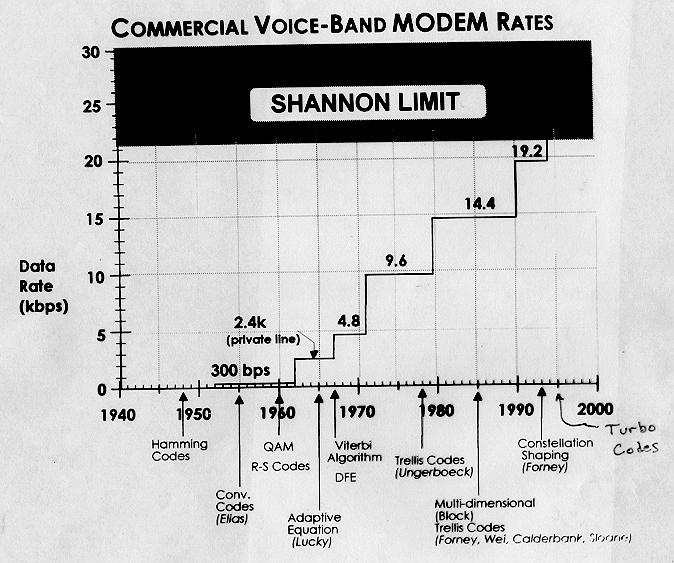
85 85
86 Data Rates for Deep Space Applications Mariner: 1969 (Mars) Pioneer 10/11: 1972/3 (Jupiter/Saturn fly-by) Voyager: 1977 (Jupiter and Saturn) Planetary Standard: 1980 s (military satellite) BVD: Big Viterbi Decoder Galileo: 1992 (Jupiter) (uses BVD) Turbo Code: 1993 Signal to Noise Ratio 86
MSIT 413: Wireless Technologies Week 3
 MSIT 413: Wireless Technologies Week 3 Michael L. Honig Department of EECS Northwestern University January 2016 Why Study Radio Propagation? To determine coverage Can we use the same channels? Must determine
MSIT 413: Wireless Technologies Week 3
 MSIT 413: Wireless Technologies Week 3 Michael L. Honig Department of EECS Northwestern University October 2017 Why Study Radio Propagation? To determine coverage Can we use the same channels? Must determine
ECE 476/ECE 501C/CS Wireless Communication Systems Winter Lecture 6: Fading
 ECE 476/ECE 501C/CS 513 - Wireless Communication Systems Winter 2004 Lecture 6: Fading Last lecture: Large scale propagation properties of wireless systems - slowly varying properties that depend primarily
ECE 476/ECE 501C/CS Wireless Communication Systems Winter Lecture 6: Fading
 ECE 476/ECE 501C/CS 513 - Wireless Communication Systems Winter 2005 Lecture 6: Fading Last lecture: Large scale propagation properties of wireless systems - slowly varying properties that depend primarily
ECE 476/ECE 501C/CS Wireless Communication Systems Winter Lecture 6: Fading
 ECE 476/ECE 501C/CS 513 - Wireless Communication Systems Winter 2003 Lecture 6: Fading Last lecture: Large scale propagation properties of wireless systems - slowly varying properties that depend primarily
Wireless Channel Propagation Model Small-scale Fading
 Wireless Channel Propagation Model Small-scale Fading Basic Questions T x What will happen if the transmitter - changes transmit power? - changes frequency? - operates at higher speed? Transmit power,
EENG473 Mobile Communications Module 3 : Week # (12) Mobile Radio Propagation: Small-Scale Path Loss
 Mobile Radio Propagation: Small-Scale Path Loss") EENG473 Mobile Communications Module 3 : Week # (12) Mobile Radio Propagation: Small-Scale Path Loss Introduction Small-scale fading is used to describe the rapid fluctuation of the amplitude of a radio
EENG473 Mobile Communications Module 3 : Week # (12) Mobile Radio Propagation: Small-Scale Path Loss Introduction Small-scale fading is used to describe the rapid fluctuation of the amplitude of a radio
EECS 380: Wireless Technologies Week 7-8
 EECS 380: Wireless Technologies Week 7-8 Michael L. Honig Northwestern University May 2018 Outline Diversity, MIMO Multiple Access techniques FDMA, TDMA OFDMA (LTE) CDMA (3G, 802.11b, Bluetooth) Random
Mobile Radio Propagation Channel Models
 Wireless Information Transmission System Lab. Mobile Radio Propagation Channel Models Institute of Communications Engineering National Sun Yat-sen University Table of Contents Introduction Propagation
The Radio Channel. COS 463: Wireless Networks Lecture 14 Kyle Jamieson. [Parts adapted from I. Darwazeh, A. Goldsmith, T. Rappaport, P.
 The Radio Channel COS 463: Wireless Networks Lecture 14 Kyle Jamieson [Parts adapted from I. Darwazeh, A. Goldsmith, T. Rappaport, P. Steenkiste] Motivation The radio channel is what limits most radio
Outline / Wireless Networks and Applications Lecture 5: Physical Layer Signal Propagation and Modulation
 Outline 18-452/18-750 Wireless Networks and Applications Lecture 5: Physical Layer Signal Propagation and Modulation Peter Steenkiste Carnegie Mellon University Spring Semester 2017 http://www.cs.cmu.edu/~prs/wirelesss17/
Chapter 2 Channel Equalization
 Chapter 2 Channel Equalization 2.1 Introduction In wireless communication systems signal experiences distortion due to fading [17]. As signal propagates, it follows multiple paths between transmitter and
Physical Layer: Outline
 18-345: Introduction to Telecommunication Networks Lectures 3: Physical Layer Peter Steenkiste Spring 2015 www.cs.cmu.edu/~prs/nets-ece Physical Layer: Outline Digital networking Modulation Characterization
Mobile & Wireless Networking. Lecture 2: Wireless Transmission (2/2)
") 192620010 Mobile & Wireless Networking Lecture 2: Wireless Transmission (2/2) [Schiller, Section 2.6 & 2.7] [Reader Part 1: OFDM: An architecture for the fourth generation] Geert Heijenk Outline of Lecture
192620010 Mobile & Wireless Networking Lecture 2: Wireless Transmission (2/2) [Schiller, Section 2.6 & 2.7] [Reader Part 1: OFDM: An architecture for the fourth generation] Geert Heijenk Outline of Lecture
Announcements : Wireless Networks Lecture 3: Physical Layer. Bird s Eye View. Outline. Page 1
 Announcements 18-759: Wireless Networks Lecture 3: Physical Layer Please start to form project teams» Updated project handout is available on the web site Also start to form teams for surveys» Send mail
Wireless Communication: Concepts, Techniques, and Models. Hongwei Zhang
 Wireless Communication: Concepts, Techniques, and Models Hongwei Zhang http://www.cs.wayne.edu/~hzhang Outline Digital communication over radio channels Channel capacity MIMO: diversity and parallel channels
Input electric signal. Transmitter. Noise and signals from other sources. Receiver. Output electric. signal. Electrical Communication System
 Electrical Communication System: Block Diagram Information Source Input Transducer Input electric signal Transmitter Transmitted signal Noise and signals from other sources Channel Destination Output Transducer
WIRELESS COMMUNICATIONS PRELIMINARIES
 WIRELESS COMMUNICATIONS Preliminaries Radio Environment Modulation Performance PRELIMINARIES db s and dbm s Frequency/Time Relationship Bandwidth, Symbol Rate, and Bit Rate 1 DECIBELS Relative signal strengths
Mobile Radio Propagation: Small-Scale Fading and Multi-path
 Mobile Radio Propagation: Small-Scale Fading and Multi-path 1 EE/TE 4365, UT Dallas 2 Small-scale Fading Small-scale fading, or simply fading describes the rapid fluctuation of the amplitude of a radio
Basic Concepts in Data Transmission
 Basic Concepts in Data Transmission EE450: Introduction to Computer Networks Professor A. Zahid A.Zahid-EE450 1 Data and Signals Data is an entity that convey information Analog Continuous values within
Fundamentals of Digital Communication
 Fundamentals of Digital Communication Network Infrastructures A.A. 2017/18 Digital communication system Analog Digital Input Signal Analog/ Digital Low Pass Filter Sampler Quantizer Source Encoder Channel
Narrow- and wideband channels
 RADIO SYSTEMS ETIN15 Lecture no: 3 Narrow- and wideband channels Ove Edfors, Department of Electrical and Information technology Ove.Edfors@eit.lth.se 27 March 2017 1 Contents Short review NARROW-BAND
Chapter 7 Multiple Division Techniques for Traffic Channels
 Introduction to Wireless & Mobile Systems Chapter 7 Multiple Division Techniques for Traffic Channels Outline Introduction Concepts and Models for Multiple Divisions Frequency Division Multiple Access
Implementation of a MIMO Transceiver Using GNU Radio
 ECE 4901 Fall 2015 Implementation of a MIMO Transceiver Using GNU Radio Ethan Aebli (EE) Michael Williams (EE) Erica Wisniewski (CMPE/EE) The MITRE Corporation 202 Burlington Rd Bedford, MA 01730 Department
Outline / Wireless Networks and Applications Lecture 3: Physical Layer Signals, Modulation, Multiplexing. Cartoon View 1 A Wave of Energy
 Outline 18-452/18-750 Wireless Networks and Applications Lecture 3: Physical Layer Signals, Modulation, Multiplexing Peter Steenkiste Carnegie Mellon University Spring Semester 2017 http://www.cs.cmu.edu/~prs/wirelesss17/
Level 6 Graduate Diploma in Engineering Wireless and mobile communications
 9210-119 Level 6 Graduate Diploma in Engineering Wireless and mobile communications Sample Paper You should have the following for this examination one answer book non-programmable calculator pen, pencil,
Project = An Adventure : Wireless Networks. Lecture 4: More Physical Layer. What is an Antenna? Outline. Page 1
 Project = An Adventure 18-759: Wireless Networks Checkpoint 2 Checkpoint 1 Lecture 4: More Physical Layer You are here Done! Peter Steenkiste Departments of Computer Science and Electrical and Computer
Unit 5 - Week 4 - Multipath Fading Environment
 2/29/207 Introduction to ireless and Cellular Communications - - Unit 5 - eek 4 - Multipath Fading Environment X Courses Unit 5 - eek 4 - Multipath Fading Environment Course outline How to access the portal
Chapter 3 Digital Transmission Fundamentals
 Chapter 3 Digital Transmission Fundamentals Characterization of Communication Channels Fundamental Limits in Digital Transmission CSE 323, Winter 200 Instructor: Foroohar Foroozan Chapter 3 Digital Transmission
Testing c2k Mobile Stations Using a Digitally Generated Faded Signal
 Testing c2k Mobile Stations Using a Digitally Generated Faded Signal Agenda Overview of Presentation Fading Overview Mitigation Test Methods Agenda Fading Presentation Fading Overview Mitigation Test Methods
Vehicle Networks. Wireless communication basics. Univ.-Prof. Dr. Thomas Strang, Dipl.-Inform. Matthias Röckl
 Vehicle Networks Wireless communication basics Univ.-Prof. Dr. Thomas Strang, Dipl.-Inform. Matthias Röckl Outline Wireless Signal Propagation Electro-magnetic waves Signal impairments Attenuation Distortion
Narrow- and wideband channels
 RADIO SYSTEMS ETIN15 Lecture no: 3 Narrow- and wideband channels Ove Edfors, Department of Electrical and Information technology Ove.Edfors@eit.lth.se 2012-03-19 Ove Edfors - ETIN15 1 Contents Short review
Small-Scale Fading I PROF. MICHAEL TSAI 2011/10/27
 Small-Scale Fading I PROF. MICHAEL TSAI 011/10/7 Multipath Propagation RX just sums up all Multi Path Component (MPC). Multipath Channel Impulse Response An example of the time-varying discrete-time impulse
LECTURE 3. Radio Propagation
 LECTURE 3 Radio Propagation 2 Simplified model of a digital communication system Source Source Encoder Channel Encoder Modulator Radio Channel Destination Source Decoder Channel Decoder Demod -ulator Components
Channel. Muhammad Ali Jinnah University, Islamabad Campus, Pakistan. Multi-Path Fading. Dr. Noor M Khan EE, MAJU
 Instructor: Prof. Dr. Noor M. Khan Department of Electronic Engineering, Muhammad Ali Jinnah University, Islamabad Campus, Islamabad, PAKISTAN Ph: +9 (51) 111-878787, Ext. 19 (Office), 186 (Lab) Fax: +9
Announcement : Wireless Networks Lecture 3: Physical Layer. A Reminder about Prerequisites. Outline. Page 1
 Announcement 18-759: Wireless Networks Lecture 3: Physical Layer Peter Steenkiste Departments of Computer Science and Electrical and Computer Engineering Spring Semester 2010 http://www.cs.cmu.edu/~prs/wirelesss10/
Revision of Lecture One
 Revision of Lecture One System blocks and basic concepts Multiple access, MIMO, space-time Transceiver Wireless Channel Signal/System: Bandpass (Passband) Baseband Baseband complex envelope Linear system:
Multi-Path Fading Channel
 Instructor: Prof. Dr. Noor M. Khan Department of Electronic Engineering, Muhammad Ali Jinnah University, Islamabad Campus, Islamabad, PAKISTAN Ph: +9 (51) 111-878787, Ext. 19 (Office), 186 (Lab) Fax: +9
Application Note 37. Emulating RF Channel Characteristics
 Application Note 37 Emulating RF Channel Characteristics Wireless communication is one of the most demanding applications for the telecommunications equipment designer. Typical signals at the receiver
EE4601 Communication Systems
 EE4601 Communication Systems Week 1 Introduction to Digital Communications Channel Capacity 0 c 2015, Georgia Institute of Technology (lect1 1) Contact Information Office: Centergy 5138 Phone: 404 894
SNS COLLEGE OF ENGINEERING COIMBATORE DEPARTMENT OF INFORMATION TECHNOLOGY QUESTION BANK
 SNS COLLEGE OF ENGINEERING COIMBATORE 641107 DEPARTMENT OF INFORMATION TECHNOLOGY QUESTION BANK EC6801 WIRELESS COMMUNICATION UNIT-I WIRELESS CHANNELS PART-A 1. What is propagation model? 2. What are the
Week 2. Topics in Wireless Systems EE584-F 03 9/9/2003. Copyright 2003 Stevens Institute of Technology - All rights reserved
 Week Topics in Wireless Systems 43 0 th Generation Wireless Systems Mobile Telephone Service Few, high-power, long-range basestations -> No sharing of spectrum -> few users -> expensive 44 Cellular Systems
CHAPTER 2 WIRELESS CHANNEL
 CHAPTER 2 WIRELESS CHANNEL 2.1 INTRODUCTION In mobile radio channel there is certain fundamental limitation on the performance of wireless communication system. There are many obstructions between transmitter
1.1 Introduction to the book
 1 Introduction 1.1 Introduction to the book Recent advances in wireless communication systems have increased the throughput over wireless channels and networks. At the same time, the reliability of wireless
WIRELESS COMMUNICATION TECHNOLOGIES (16:332:546) LECTURE 5 SMALL SCALE FADING
 LECTURE 5 SMALL SCALE FADING") WIRELESS COMMUNICATION TECHNOLOGIES (16:332:546) LECTURE 5 SMALL SCALE FADING Instructor: Dr. Narayan Mandayam Slides: SabarishVivek Sarathy A QUICK RECAP Why is there poor signal reception in urban clutters?
WIRELESS COMMUNICATION TECHNOLOGIES (16:332:546) LECTURE 5 SMALL SCALE FADING Instructor: Dr. Narayan Mandayam Slides: SabarishVivek Sarathy A QUICK RECAP Why is there poor signal reception in urban clutters?
Muhammad Ali Jinnah University, Islamabad Campus, Pakistan. Fading Channel. Base Station
 Fading Lecturer: Assoc. Prof. Dr. Noor M Khan Department of Electronic Engineering, Muhammad Ali Jinnah University, Islamabad Campus, Islamabad, PAKISTAN Ph: +9 (51) 111-878787, Ext. 19 (Office), 186 (ARWiC
Lecture 1 Wireless Channel Models
 MIMO Communication Systems Lecture 1 Wireless Channel Models Prof. Chun-Hung Liu Dept. of Electrical and Computer Engineering National Chiao Tung University Spring 2017 2017/3/2 Lecture 1: Wireless Channel
UNIT- 7. Frequencies above 30Mhz tend to travel in straight lines they are limited in their propagation by the curvature of the earth.
 UNIT- 7 Radio wave propagation and propagation models EM waves below 2Mhz tend to travel as ground waves, These wave tend to follow the curvature of the earth and lose strength rapidly as they travel away
OFDMA and MIMO Notes
 OFDMA and MIMO Notes EE 442 Spring Semester Lecture 14 Orthogonal Frequency Division Multiplexing (OFDM) is a digital multi-carrier modulation technique extending the concept of single subcarrier modulation
Wireless Communication Fundamentals Feb. 8, 2005
 Wireless Communication Fundamentals Feb. 8, 005 Dr. Chengzhi Li 1 Suggested Reading Chapter Wireless Communications by T. S. Rappaport, 001 (version ) Rayleigh Fading Channels in Mobile Digital Communication
Wireless Networked Systems. Lec #1b: PHY Basics
 Wireless Networked Systems CS 795/895 - Spring 2013 Lec #1b: PHY Basics Tamer Nadeem Dept. of Computer Science Wireless Communication Page 2 Spring 2013 CS 795/895 - Wireless Networked Systems Radio Signal
Chapter 1 Acknowledgment:
 Chapter 1 Acknowledgment: This material is based on the slides formatted by Dr Sunilkumar S. Manvi and Dr Mahabaleshwar S. Kakkasageri, the authors of the textbook: Wireless and Mobile Networks, concepts
Chapter 2: Wireless Transmission. Mobile Communications. Spread spectrum. Multiplexing. Modulation. Frequencies. Antenna. Signals
 Mobile Communications Chapter 2: Wireless Transmission Frequencies Multiplexing Signals Spread spectrum Antenna Modulation Signal propagation Cellular systems Prof. Dr.-Ing. Jochen Schiller, http://www.jochenschiller.de/
Chapter 3 Data Transmission COSC 3213 Summer 2003
 Chapter 3 Data Transmission COSC 3213 Summer 2003 Courtesy of Prof. Amir Asif Definitions 1. Recall that the lowest layer in OSI is the physical layer. The physical layer deals with the transfer of raw
EC 551 Telecommunication System Engineering. Mohamed Khedr
 EC 551 Telecommunication System Engineering Mohamed Khedr http://webmail.aast.edu/~khedr 1 Mohamed Khedr., 2008 Syllabus Tentatively Week 1 Week 2 Week 3 Week 4 Week 5 Week 6 Week 7 Week 8 Week 9 Week
CSCD 433 Network Programming Fall Lecture 5 Physical Layer Continued
 CSCD 433 Network Programming Fall 2016 Lecture 5 Physical Layer Continued 1 Topics Definitions Analog Transmission of Digital Data Digital Transmission of Analog Data Multiplexing 2 Different Types of
Downloaded from 1
 VII SEMESTER FINAL EXAMINATION-2004 Attempt ALL questions. Q. [1] How does Digital communication System differ from Analog systems? Draw functional block diagram of DCS and explain the significance of
COMMUNICATION SYSTEMS
 COMMUNICATION SYSTEMS 4TH EDITION Simon Hayhin McMaster University JOHN WILEY & SONS, INC. Ш.! [ BACKGROUND AND PREVIEW 1. The Communication Process 1 2. Primary Communication Resources 3 3. Sources of
Wireless Communications
 2. Physical Layer DIN/CTC/UEM 2018 Periodic Signal Periodic signal: repeats itself in time, that is g(t) = g(t + T ) in which T (given in seconds [s]) is the period of the signal g(t) The number of cycles
QUESTION BANK SUBJECT: DIGITAL COMMUNICATION (15EC61)
") QUESTION BANK SUBJECT: DIGITAL COMMUNICATION (15EC61) Module 1 1. Explain Digital communication system with a neat block diagram. 2. What are the differences between digital and analog communication systems?
QUESTION BANK SUBJECT: DIGITAL COMMUNICATION (15EC61) Module 1 1. Explain Digital communication system with a neat block diagram. 2. What are the differences between digital and analog communication systems?
Performance Evaluation Of Digital Modulation Techniques In Awgn Communication Channel
 Performance Evaluation Of Digital Modulation Techniques In Awgn Communication Channel Oyetunji S. A 1 and Akinninranye A. A 2 1 Federal University of Technology Akure, Nigeria 2 MTN Nigeria Abstract The
CS441 Mobile & Wireless Computing Communication Basics
 Department of Computer Science Southern Illinois University Carbondale CS441 Mobile & Wireless Computing Communication Basics Dr. Kemal Akkaya E-mail: kemal@cs.siu.edu Kemal Akkaya Mobile & Wireless Computing
Multiplexing Module W.tra.2
 Multiplexing Module W.tra.2 Dr.M.Y.Wu@CSE Shanghai Jiaotong University Shanghai, China Dr.W.Shu@ECE University of New Mexico Albuquerque, NM, USA 1 Multiplexing W.tra.2-2 Multiplexing shared medium at
Making Noise in RF Receivers Simulate Real-World Signals with Signal Generators
 Making Noise in RF Receivers Simulate Real-World Signals with Signal Generators Noise is an unwanted signal. In communication systems, noise affects both transmitter and receiver performance. It degrades
Antennas & Propagation. CSG 250 Fall 2007 Rajmohan Rajaraman
 Antennas & Propagation CSG 250 Fall 2007 Rajmohan Rajaraman Introduction An antenna is an electrical conductor or system of conductors o Transmission - radiates electromagnetic energy into space o Reception
Digital Communications over Fading Channel s
 over Fading Channel s Instructor: Prof. Dr. Noor M Khan Department of Electronic Engineering, Muhammad Ali Jinnah University, Islamabad Campus, Islamabad, PAKISTAN Ph: +9 (51) 111-878787, Ext. 19 (Office),
UNIK4230: Mobile Communications Spring 2013
 UNIK4230: Mobile Communications Spring 2013 Abul Kaosher abul.kaosher@nsn.com Mobile: 99 27 10 19 1 UNIK4230: Mobile Communications Propagation characteristis of wireless channel Date: 07.02.2013 2 UNIK4230:
Terminology (1) Chapter 3. Terminology (3) Terminology (2) Transmitter Receiver Medium. Data Transmission. Direct link. Point-to-point.
 Chapter 3. Terminology (3) Terminology (2) Transmitter Receiver Medium. Data Transmission. Direct link. Point-to-point.") Terminology (1) Chapter 3 Data Transmission Transmitter Receiver Medium Guided medium e.g. twisted pair, optical fiber Unguided medium e.g. air, water, vacuum Spring 2012 03-1 Spring 2012 03-2 Terminology
Terminology (1) Chapter 3 Data Transmission Transmitter Receiver Medium Guided medium e.g. twisted pair, optical fiber Unguided medium e.g. air, water, vacuum Spring 2012 03-1 Spring 2012 03-2 Terminology
Revision of Lecture One
 Revision of Lecture One System block Transceiver Wireless Channel Signal / System: Bandpass (Passband) Baseband Baseband complex envelope Linear system: complex (baseband) channel impulse response Channel:
Contents. Telecom Service Chae Y. Lee. Data Signal Transmission Transmission Impairments Channel Capacity
 Data Transmission Contents Data Signal Transmission Transmission Impairments Channel Capacity 2 Data/Signal/Transmission Data: entities that convey meaning or information Signal: electric or electromagnetic
Wireless Transmission in Cellular Networks
 Wireless Transmission in Cellular Networks Frequencies Signal propagation Signal to Interference Ratio Channel capacity (Shannon) Multipath propagation Multiplexing Spatial reuse in cellular systems Antennas
Communication Channels
 Communication Channels wires (PCB trace or conductor on IC) optical fiber (attenuation 4dB/km) broadcast TV (50 kw transmit) voice telephone line (under -9 dbm or 110 µw) walkie-talkie: 500 mw, 467 MHz
EITF25 Internet Techniques and Applications L2: Physical layer. Stefan Höst
 EITF25 Internet Techniques and Applications L2: Physical layer Stefan Höst Data vs signal Data: Static representation of information For storage Signal: Dynamic representation of information For transmission
Digital Communication System
 Digital Communication System Purpose: communicate information at required rate between geographically separated locations reliably (quality) Important point: rate, quality spectral bandwidth, power requirements
E-716-A Mobile Communications Systems. Lecture #2 Basic Concepts of Wireless Transmission (p1) Instructor: Dr. Ahmad El-Banna
 Instructor: Dr. Ahmad El-Banna") October 2014 Ahmad El-Banna Integrated Technical Education Cluster At AlAmeeria E-716-A Mobile Communications Systems Lecture #2 Basic Concepts of Wireless Transmission (p1) Instructor: Dr. Ahmad El-Banna
October 2014 Ahmad El-Banna Integrated Technical Education Cluster At AlAmeeria E-716-A Mobile Communications Systems Lecture #2 Basic Concepts of Wireless Transmission (p1) Instructor: Dr. Ahmad El-Banna
Lecture 3: Wireless Physical Layer: Modulation Techniques. Mythili Vutukuru CS 653 Spring 2014 Jan 13, Monday
 Lecture 3: Wireless Physical Layer: Modulation Techniques Mythili Vutukuru CS 653 Spring 2014 Jan 13, Monday Modulation We saw a simple example of amplitude modulation in the last lecture Modulation how
Fundamentals of Wireless Communication
 Fundamentals of Wireless Communication David Tse University of California, Berkeley Pramod Viswanath University of Illinois, Urbana-Champaign Fundamentals of Wireless Communication, Tse&Viswanath 1. Introduction
Lecture 9: Spread Spectrum Modulation Techniques
 Lecture 9: Spread Spectrum Modulation Techniques Spread spectrum (SS) modulation techniques employ a transmission bandwidth which is several orders of magnitude greater than the minimum required bandwidth
Lecture 3: Data Transmission
 Lecture 3: Data Transmission 1 st semester 1439-2017 1 By: Elham Sunbu OUTLINE Data Transmission DATA RATE LIMITS Transmission Impairments Examples DATA TRANSMISSION The successful transmission of data
Point-to-Point Communications
 Point-to-Point Communications Key Aspects of Communication Voice Mail Tones Alphabet Signals Air Paper Media Language English/Hindi English/Hindi Outline of Point-to-Point Communication 1. Signals basic
CSCD 433 Network Programming Fall Lecture 5 Physical Layer Continued
 CSCD 433 Network Programming Fall 2016 Lecture 5 Physical Layer Continued 1 Topics Definitions Analog Transmission of Digital Data Digital Transmission of Analog Data Multiplexing 2 Different Types of
Empirical Path Loss Models
 Empirical Path Loss Models 1 Free space and direct plus reflected path loss 2 Hata model 3 Lee model 4 Other models 5 Examples Levis, Johnson, Teixeira (ESL/OSU) Radiowave Propagation August 17, 2018 1
Wireless Networks (PHY): Design for Diversity
: Design for Diversity") Wireless Networks (PHY): Design for Diversity Y. Richard Yang 9/20/2012 Outline Admin and recap Design for diversity 2 Admin Assignment 1 questions Assignment 1 office hours Thursday 3-4 @ AKW 307A 3 Recap:
Wireless Networks (PHY): Design for Diversity Y. Richard Yang 9/20/2012 Outline Admin and recap Design for diversity 2 Admin Assignment 1 questions Assignment 1 office hours Thursday 3-4 @ AKW 307A 3 Recap:
Wireless Physical Layer Concepts: Part II
 Wireless Physical Layer Concepts: Part II Raj Jain Professor of CSE Washington University in Saint Louis Saint Louis, MO 63130 Jain@cse.wustl.edu Audio/Video recordings of this lecture are available at:
Written Exam Channel Modeling for Wireless Communications - ETIN10
 Written Exam Channel Modeling for Wireless Communications - ETIN10 Department of Electrical and Information Technology Lund University 2017-03-13 2.00 PM - 7.00 PM A minimum of 30 out of 60 points are
Lecture #2. EE 471C / EE 381K-17 Wireless Communication Lab. Professor Robert W. Heath Jr.
 Lecture #2 EE 471C / EE 381K-17 Wireless Communication Lab Professor Robert W. Heath Jr. Preview of today s lecture u Introduction to digital communication u Components of a digital communication system
ECE 476/ECE 501C/CS Wireless Communication Systems Winter Lecture 9: Multiple Access, GSM, and IS-95
 ECE 476/ECE 501C/CS 513 - Wireless Communication Systems Winter 2003 Lecture 9: Multiple Access, GSM, and IS-95 Outline: Two other important issues related to multiple access space division with smart
Opportunistic Communication in Wireless Networks
 Opportunistic Communication in Wireless Networks David Tse Department of EECS, U.C. Berkeley October 10, 2001 Networking, Communications and DSP Seminar Communication over Wireless Channels Fundamental
About Homework. The rest parts of the course: focus on popular standards like GSM, WCDMA, etc.
 About Homework The rest parts of the course: focus on popular standards like GSM, WCDMA, etc. Good news: No complicated mathematics and calculations! Concepts: Understanding and remember! Homework: review
Lecture 2 Physical Layer - Data Transmission
 DATA AND COMPUTER COMMUNICATIONS Lecture 2 Physical Layer - Data Transmission Mei Yang Based on Lecture slides by William Stallings 1 DATA TRANSMISSION The successful transmission of data depends on two
Transmission Impairments
 1/13 Transmission Impairments Surasak Sanguanpong nguan@ku.ac.th http://www.cpe.ku.ac.th/~nguan Last updated: 11 July 2000 Transmissions Impairments 1/13 Type of impairments 2/13 Attenuation Delay distortion
Chapter 7. Multiple Division Techniques
 Chapter 7 Multiple Division Techniques 1 Outline Frequency Division Multiple Access (FDMA) Division Multiple Access (TDMA) Code Division Multiple Access (CDMA) Comparison of FDMA, TDMA, and CDMA Walsh
Receiver Designs for the Radio Channel
 Receiver Designs for the Radio Channel COS 463: Wireless Networks Lecture 15 Kyle Jamieson [Parts adapted from C. Sodini, W. Ozan, J. Tan] Today 1. Delay Spread and Frequency-Selective Fading 2. Time-Domain
CS-435 spring semester Network Technology & Programming Laboratory. Stefanos Papadakis & Manolis Spanakis
 CS-435 spring semester 2016 Network Technology & Programming Laboratory University of Crete Computer Science Department Stefanos Papadakis & Manolis Spanakis CS-435 Lecture preview Wireless Networking
CS 218 Fall 2003 October 23, 2003
 CS 218 Fall 2003 October 23, 2003 Cellular Wireless Networks AMPS (Analog) D-AMPS (TDMA) GSM CDMA Reference: Tanenbaum Chpt 2 (pg 153-169) Cellular Wireless Network Evolution First Generation: Analog AMPS:
Digital Communication System
 Digital Communication System Purpose: communicate information at certain rate between geographically separated locations reliably (quality) Important point: rate, quality spectral bandwidth requirement
Unit-1 The Cellular Concept
 Unit-1 The Cellular Concept 1.1 Introduction to Cellular Systems Solves the problem of spectral congestion and user capacity. Offer very high capacity in a limited spectrum without major technological
Lecture Fundamentals of Data and signals
 IT-5301-3 Data Communications and Computer Networks Lecture 05-07 Fundamentals of Data and signals Lecture 05 - Roadmap Analog and Digital Data Analog Signals, Digital Signals Periodic and Aperiodic Signals
Satellite Communications: Part 4 Signal Distortions & Errors and their Relation to Communication Channel Specifications. Howard Hausman April 1, 2010
 Satellite Communications: Part 4 Signal Distortions & Errors and their Relation to Communication Channel Specifications Howard Hausman April 1, 2010 Satellite Communications: Part 4 Signal Distortions
EC 551 Telecommunication System Engineering. Mohamed Khedr
 EC 551 Telecommunication System Engineering Mohamed Khedr http://webmail.aast.edu/~khedr 1 Mohamed Khedr., 2008 Syllabus Tentatively Week 1 Week 2 Week 3 Week 4 Week 5 Week 6 Week 7 Week 8 Week 9 Week