Precision Calibration & Interconnect Solutions
|
|
|
- Herbert Gregory
- 5 years ago
- Views:
Transcription
1

2 Also Available from Maury Microwave Precision Calibration & Interconnect Solutions Maury Precision VNA Calibration Kits For Fixed Load, Sliding Load and TRL Calibration of Keysight, Rhode & Schwarz and Anritsu VNAs 1.85mm, 2.4mm, 2.92mm, 3.5mm, 7mm, Type N, TNC, BNC, and Waveguide VNA Calibration Kits Precision Fixed Terminations Waveguide (301 series) Sliding Terminations 2.4mm, 2.92mm, 3.5mm, 7mm, Type N, and TNC Fixed Flush and Fixed Offset Shorts Waveguide Fixed Flush Shorts Model Series 344 Waveguide Fixed Offset Shorts Model Series 340 Opens Precision Air Lines Precision Mismatches Precision Adapters, Cables, Connectors, Waveguide Components and Noise Calibration Systems Calibration-Grade (Metrology) Adapters NMD1.85mm/2.4mm/2.92mm/3.5mm Test Port Adapters 2633, 7809, 7909, 8719, 8009, and 8829 Series 1.85mm Adapters In-Series and Between-Series 2.4mm Adapters In-Series and Between-Series 2.92mm Adapters In-Series and Between-Series 3.5mm Adapters In-Series and Between-Series 3.5mm (QT3.5mm ) Quick Test Adapters 8006 Series (U.S. Patent No. 6,210,221) 7mm Adapters Between-Series Type N Adapters In-Series and Between-Series TNC Adapters In-Series and Between-Series BNC & SMA Adapters Waveguide-To-Coaxial Adapters Right Angle Launch WR90 WR22 to 2.4mm, 2.92mm, 3.5mm, 7mm, and Type N Waveguide To Coaxial Adapters End Launch WR430 WR22 to 2.4mm, 2.92mm, 3.5mm, 7mm, and Type N Space Qualified Adapters Waveguide Transmission Lines and Test Port Adapters Straight Sections and Transitions ColorConnect Precision Adapters Series CC-185, CC-24, CC-292, CC-35, CC-N and CC-SMA Test Essentials Lab Adapters Series TE-185, TE-24, TE-292, TE-35, TE-N and TE-SMA Test Port Cable Assemblies Series 8944C, 8946C and 8948C Stability Microwave/RF Cable Assemblies Series SC-185, SC-24, SC-292, SC-35 and SC-N Utility Microwave/RF Cable Assemblies Series UC-N and UC-SMA AT-Series Precision Attenuators Torque Wrenches Connector Gages and Connector Gage Kits Coaxial Stub Tuners Noise Calibration Systems and Components Cryogenic Noise Terminations (Cold Loads) MT7118J 7mm Coaxial Cryogenic Terminations DC to 18.0 GHz Waveguide Cryogenic Terminations MT70xx Series Cryogenic Termination Accessories Noise Calibration Swept Data Module MT7250 Series Ambient Terminations Thermal Noise Terminations (Hot Loads) Coaxial Thermal Termination MT7108B Waveguide Thermal Terminations MT70xx Series Thermal Terminations Options and Accessories

3 MAURY MICROWAVE CORPORATION 1

4 MAURY MICROWAVE CORPORATION 2
5 CONTENTS Maury Device Characterization Solutions Model Index General Information About Maury Microwave Maury s Strategic Alliances In The Test & Measurement Industry Maury Microwave Corporation ISO 9001:2008 with AS9100C Documentation Calibration and Repair Services Calibration Services Repair Services IVCAD Advanced Measurement & Modeling Software.. 11 MT930 Series IVCAD Software Suite Models ATSv5 Automated Tuner System Software MT993 Series ATSv5 Software Suite Models MT993A Power Characterization Application Software MT993B Noise Characterization Application Software MT993B High Speed Noise Parameter Measurement Option MT993D Intermod Distortion (IMD), Adjacent Channel Power (ACP) and Error Vector Magnitude (EVM) Application Software Optional Software Features AMTSv3 Automated Mobile Test System Software MT910 Series AMTSv3 Automated Mobile Test System Software Models & Supported Wireless Data Communication Standards Automated Tuners General Information LXI -Certified High-Gamma Automated Tuners (HGT ) MHz TO 8 GHz TO 8.0 GHz LXI -Certified 7mm Automated Tuners TO 18 GHz LXI -Certified 3.5mm Automated Tuners TO 26.5 GHz LXI -Certified 2.4mm Automated Tuners To 50 GHz LXI -Certified 1.85mm Automated Tuners To 65 GHz Millimeter-Wave Automated Tuners TO 110 GHz LXI -Certified Multi-Harmonic Automated Tuners TO 26.5 GHz Automated Sliding Shorts TO 18.0 GHz Wide Matching Range Slide Screw Tuners Series MST981, MST982, MST983 & MST Pre-Matching Probe Mounts Series MT MT Series Noise Receiver Modules and Noise Switching Modules Low-Loss Couplers Low-Loss, High Directivity, High Power Couplers for Load Pull and Other Power Applications Anteverta Low-Loss Coaxial Multiplexers MT964 Load Pull Test Fixtures Low-Loss Test Fixtures For Load Pull and Other Power Applications Mixed-Signal Active Load Pull System MHz to 40.0 GHz Pulsed IV Systems AMCAD Engineering's PIV/PLP Family of Pulsed IV Systems RF Device Characterization System Integration MHz to 110 GHz Measurement and Modeling Device Characterization Services MAURY MICROWAVE CORPORATION 3
6 Model Index MODEL PAGE MODEL PAGE SOFTWARE PRODUCTS MT910 AMTSv3 - Automated Mobile Phone Tester MT910A AMTSv3 - GSM Standard MT910B AMTSv3 - WCDMA Standard MT910C AMTSv3 - CDMA2000 Standard MT910D AMTSv3 - LTE Standard MT910E AMTSv3 - TD-SCDMA Standard MT930 IVCAD - Advanced Measurement & Modeling Software.. 11, 42, 44, 46, 48, 50, 52, 56, 58, 60 MT930A IVCAD - Basic Application... 11, 14 MT930B IVCAD - Visualization Suite... 11, 14 MT930C IVCAD - Vector-Receiver Load Pull... 11, 15, 17-19, 22 MT930E IVCAD - IV Curves for Load Pull... 11, 17 MT930F IVCAD - Basic S-Parameters... 11, 17 MT930G IVCAD - Time-Domain Waveforms... 11, 18 MT930H IVCAD - Active Load Pull... 11, MT930J IVCAD - Pulsed IV Curves... 11, 21, 23 MT930K IVCAD - Pulsed S-Parameters... 11, 21, 23 MT930L IVCAD - Scripting Language... 11, 22 MT930M1 IVCAD - Linear Model Extraction... 11, MT930M2A IVCAD - Non-linear Model Extraction, III-V... 11, MT930M2B IVCAD - Non-linear Model Extraction, LDMOS... 11, MT930Q IVCAD - Stability Analysis Tool (STAN)... 11, 26 MT930R1 IVCAD - Behavioral Model Extraction,. Short-Term Memory Effects...11 MT930R2 IVCAD - Behavioral Model Extraction,. Long-Term Memory Effects...11 MT993 ATSv5 - Automated Tuner System Software MT993A ATSv5 - Power Measurement Software , MT993B ATSv5 - Noise Parameter Measurement Software , 31-32, 34 MT993B01 ATSv5 - Ultra-Fast Noise Parameter Measurement Option.. 28, 32 MT993C ATSv5 - Power & Noise Software Suite... 29, 31, MT993D ATSv5 - IMD, ACP and EVM Option , 33 MT993E ATSv5 - Programmers Edition MT993F ATSv5 - System Control Option... 28, 34 MT993G ATSv5 - DC IV Curve Option... 28, 34 MT993H ATSv5 - Harmonic Source/Load Pull Option... 28, 34 MT993J ATSv5 - Fixture Characterization Option... 28, 34 AUTOMATED TUNERS MT975A Millimeter Wave Automated Tuner (33-50 GHz)... 37, 55 MT977A Millimeter Wave Automated Tuner (50-75 GHz)... 37, 55 MT978A Millimeter Wave Automated Tuner (60-90 GHz) MT979A Millimeter Wave Automated Tuner MT981BL10 LX! High-Power Automated Tuner ( GHz) MT981BL15 LX! High-Power Automated Tuner ( GHz) MT981BL18 LX! High-Power Automated Tuner ( GHz) MT981EL10 LXI High-Power Automated Tuner ( GHz) MT981HL13 LX! High-Gamma Automated Tuner ( GHz)... 37, AUTOMATED TUNERS (continued) MT981ML01 LXI Multi-Harmonic Automated Tuner ( GHz) MT981VL10 LXI High-Power Automated Tuner ( GHz) MT982AL02 LXI 7mm Automated Tuner ( GHz)...47 MT982GL01 LXI 7mm Automated Tuner ( GHz) MT982BL01 LXI 7mm Automated Tuner ( GHz)... 47, 84 MT982EL30 LXI 7mm Automated Tuner ( GHz) MT982ML01 LXI Multi-Harmonic Automated Tuner ( GHz) MT983BL01 LXI 3.5mm Automated Tuner ( GHz)... 37, MT983ML01 LXI 3.5mm Multi-Harmonic Tuner ( GHz) MT984AL01 2.4mm Automated Tuner (8-50 GHz)... 37, 50-51, 62, 83 MT985AL mm Automated Tuner (8-65 GHz)... 37, MANUAL TUNERS; COAXIAL SLIDE SCREW TUNERS MST981B35 Coaxial Slide Screw Tuner (3.5mm GHz) MST981EN Coaxial Slide Screw Tuner (Type N GHz) MST981E35 Coaxial Slide Screw Tuner (3.5mm GHz)...61 MST982VN Coaxial Slide Screw Tuner (Type N GHz) MST982V35 Coaxial Slide Screw Tuner (3.5mm GHz) MST982BN Coaxial Slide Screw Tuner (Type N GHz) MST982B35 Coaxial Slide Screw Tuner (3.5mm GHz) MST982AN Coaxial Slide Screw Tuner (Type N GHz) MST982A35 Coaxial Slide Screw Tuner (3.5mm GHz) ACCESSORIES MT7553A03 Noise Receiver Module ( GHz) MT7553B Noise Receiver Module ( GHz) MT7553B01 Noise Receiver Module ( GHz) MT7553B03 Noise Receiver Module ( GHz) MT7553M10 Noise Receiver Module ( GHz) MT7553M12 Noise Receiver Module ( GHz) MT7553M15 Noise Receiver Module ( GHz) MT7553N26 Noise Switching Module ( GHz) MT7553N50 Noise Switching Module ( GHz) MT964A1-50 7mm Load Pull Test Fixture (100 MHz 18 GHz) MT964A mm Load Pull Test Fixture (100 MHz 18 GHz) MT964A mm Load Pull Test Fixture (100 MHz 18 GHz) MT964C1-50 7mm Load Pull Test Fixture (800 MHz 18 GHz)...70 MT964C mm Load Pull Test Fixture (800 MHz 18 GHz) MT964C mm Load Pull Test Fixture (100 MHz 18 GHz) MT964C1-10 7mm Load Pull Test Fixture (800 MHz 18 GHz) MT964C mm Load Pull Test Fixture (800 MHz 18 GHz) MT964C mm Load Pull Test Fixture (100 MHz 18 GHz) MT1020C ATS Power Distribution Hub... 55, MT902A1 Basic Pre-Matching Probe Mount (DC 50 GHz)) MT902A2 High-Freq. Pre-Matching Probe Mount ( GHz) MT902A3 Low-Freq. Pre-Matching Probe Mount ( GHz) MT902A5 Basic Pre-Matching Probe Mount (DC 50 GHz)) MT902A6 High-Freq. Pre-Matching Probe Mount ( GHz) MT902A7 Low-Freq. Pre-Matching Probe Mount ( GHz) MAURY MICROWAVE CORPORATION 4
7 Model Index MODEL PAGE MODEL PAGE ACCESSORIES (continued) MT902C1 Basic Pre-Matching Probe Mount (DC-26.5 GHz) MT902C2 High-Freq. Pre-Matching Probe Mount ( GHz) MT902C5 Basic Pre-Matching Probe Mount (DC-26.5 GHz) MT902C6 High-Freq. Pre-Matching Probe Mount ( GHz) MT999A Automated Sliding Short ( GHz) MT999B Automated Sliding Short ( GHz) MT999D Automated Sliding Short (0.4 4 GHz) RF DEVICE CHARACTERIZATION SYSTEM INTEGRATION MT900 Probe Station Integration... 51, 53, 55, 82 ADVANCED RF DEVICE CHARACTERIZATION SYSTEMS MT1000HF2 Mixed-Signal Active Load Pull System ( GHz) MT1000HF4 Mixed-Signal Active Load Pull System ( GHz) MT1000A2 Mixed-Signal Active Load Pull System ( GHz) MT1000A4 Mixed-Signal Active Load Pull System ( GHz) MT1000B2 Mixed-Signal Active Load Pull System ( GHz) MT1000B4 Mixed-Signal Active Load Pull System ( GHz) MT1000D2 Mixed-Signal Active Load Pull System ( GHz) MT1000D4 Mixed-Signal Active Load Pull System ( GHz) MT1000E2 Mixed-Signal Active Load Pull System ( GHz) MT1000E4 Mixed-Signal Active Load Pull System ( GHz) MT2000HF2-60 Mixed-Signal Active Load Pull System ( GHz) MT2000HF2-120 Mixed-Signal Active Load Pull System ( GHz) MT2000HF2-240 Mixed-Signal Active Load Pull System ( GHz) MT2000HF4-60 Mixed-Signal Active Load Pull System ( GHz) MT2000HF4-120 Mixed-Signal Active Load Pull System ( GHz) MT2000HF4-240 Mixed-Signal Active Load Pull System ( GHz) MT2000A2-60 Mixed-Signal Active Load Pull System ( GHz) MT2000A2-120 Mixed-Signal Active Load Pull System ( GHz) MT2000A2-240 Mixed-Signal Active Load Pull System ( GHz) MT2000A4-60 Mixed-Signal Active Load Pull System ( GHz) MT2000A4-120 Mixed-Signal Active Load Pull System ( GHz) MT2000A4-240 Mixed-Signal Active Load Pull System ( GHz) MT2000B2-60 Mixed-Signal Active Load Pull System ( GHz) MT2000B2-120 Mixed-Signal Active Load Pull System ( GHz) MT2000B2-240 Mixed-Signal Active Load Pull System ( GHz) MT2000B4-60 Mixed-Signal Active Load Pull System ( GHz) MT2000B4-120 Mixed-Signal Active Load Pull System ( GHz) MT2000B4-240 Mixed-Signal Active Load Pull System ( GHz) MT2000D2-60 Mixed-Signal Active Load Pull System ( GHz) MT2000D2-120 Mixed-Signal Active Load Pull System ( GHz) MT2000D2-240 Mixed-Signal Active Load Pull System ( GHz) MT2000D4-60 Mixed-Signal Active Load Pull System ( GHz) MT2000D4-120 Mixed-Signal Active Load Pull System ( GHz) MT2000D4-240 Mixed-Signal Active Load Pull System ( GHz) MT2000E2-60 Mixed-Signal Active Load Pull System ( GHz) MT2000E2-120 Mixed-Signal Active Load Pull System ( GHz) ADVANCED RF DEVICE CHARACTERIZATION SYSTEMS (continued) MT2000E2-240 Mixed-Signal Active Load Pull System ( GHz) MT2000E2-60 Mixed-Signal Active Load Pull System ( GHz) MT2000E2-120 Mixed-Signal Active Load Pull System ( GHz) MT2000E2-240 Mixed-Signal Active Load Pull System ( GHz) ADVANCED RF DEVICE CHARACTERIZATION SYSTEMS SOFTWARE MODULES MT2001A MT2000 Power Measurements Software Module...74 MT2001B MT2000 Modulated Measurements Software Module...74 MT2001C MT2000 Two-Tone Measurements Software Module...74 MT2001D MT2000 NVNA (Time Domain) Software Module...74 MT2001E MT2000 External Control Software Module...74 MT2001F MT2000 Visualization Software Module...74 AMCAD ENGINEERING PULSED IV SYSTEMS PIV AMCAD Pulsed IV Systems... 13, 76-78, 80 PLP AMCAD Pulsed Load Pull Systems TP SERIES TRIPLEXERS TP Precision Low Loss Coaxial Triplexers TP-1822 Precision Low Loss Coaxial Triplexers TP-2226 Precision Low Loss Coaxial Triplexers TP-2631 Precision Low Loss Coaxial Triplexers DP SERIES DIPLEXERS DP Precision Low Loss Coaxial Diplexers DP-1220 Precision Low Loss Coaxial Diplexers DP-1823 Precision Low Loss Coaxial Diplexers DP-2232 Precision Low Loss Coaxial Diplexers DP-2942 Precision Low Loss Coaxial Diplexers DP-3957 Precision Low Loss Coaxial Diplexers LOW-LOSS COUPLERS LLC18-7 Low-Loss Couplers ( GHz) LLC18-N-FF Low-Loss Couplers ( GHz) LLC18-N-MF Low-Loss Couplers ( GHz) LLC18-N-MM Low-Loss Couplers ( GHz) LLC34-35-FF Low-Loss Couplers ( GHz) LLC34-35-MF Low-Loss Couplers ( GHz)) LLC34-35-MM Low-Loss Couplers ( GHz) MAURY MICROWAVE CORPORATION 5
8 General Information How To Order Maury Products Orders may be placed directly with the factory or in care of your nearest Maury sales representative. For orders originating outside the United States, we recommend placing the order through your local Maury sales representative. Maury maintains an extensive network of sales representatives throughout the world. To find your local Maury sales representative use the interactive index on our web site at maurymw.com/support/find-sales-rep.php. Pricing and Quotations Prices for Maury products are those prevailing when an order is placed except when the price is established by formal quotation. Maury Microwave reserves the right to change prices at any time without notice. Price and availability of products with custom or special features must be verified by a valid, formal factory quotation. Maury quotations are valid for a maximum of 30 days. Extensions beyond 30 days can be granted only by the factory. Terms of Sale Domestic terms are net 30 days from the date of invoice for customers with established credit F.O.B. Ontario, California. Please refer to Maury Form 228 for complete terms and conditions. For International sales, please refer to Maury Form 250. Sales to Canada are covered by Maury Form 251. These forms are available on request, or may be found on our web site in PDF format. Shipment All shipments are at the buyer s expense. Shipments are normally made using methods and carriers specified by the customer. In the absence of specific instructions, Maury will ship at our discretion by the most advantageous method. All shipments are F.O.B. the Maury factory in Ontario, California (U.S.A.) and, unless otherwise specified, will be insured at full value at the customer s expense. Shipments are packed to provide ample safety margin against transit damage, and there is no charge for regular packing requirements. Additional charges apply to MILSPEC preservation, packaging, packing and marking. Product and Specifications Changes The information, illustrations and specifications contained in this catalog were current at the time of publication. Maury Microwave is continually striving to upgrade and improve our product offering and therefore, reserves the right to change specifications, designs and models without notice and without incurring any obligation to incorporate new features on products previously sold. Because products are changed or improved with time, please consult your local Maury representative, or our Sales Department, for current pricing and product information before placing orders. Product Selection Maury representatives and sales office personnel are well qualified to provide assistance in product selection, and current pricing and availability. Our factory applications engineers are ready to assist you with any technical or applications questions you may have. Service and Support Warranty Maury Microwave is highly confident that our products will perform to the high levels that our customers have come to expect. As an expression of that confidence, our products are warranted as noted in the abbreviated warranty statements below. (For a complete statement of the hardware warranty, please see Form 228, Terms and Conditions of Sales. For a complete statement of the software warranty, please see Form 273, Maury License Agreement.) Maury Microwave hardware products are warranted against defects in material and workmanship for a period of one year after delivery to the original purchaser. If a Maury manufactured hardware product is returned to the factory with transportation prepaid and it is determined by Maury that the product is defective and under warranty, Maury will service the product, including repair or replacement of any defective parts thereof. This constitutes Maury s entire obligation under this warranty. Maury warrants that, for a period of ninety (90) days following purchase, software products, including firmware for use with and properly installed on a Maury designated hardware product, will operate substantially in accordance with published specifications, and that the media on which the product is supplied is free from defects in material and workmanship. Maury s sole obligation under this warranty is to repair or replace a nonconforming product and/or media, provided Maury is notified of nonconformance during the warranty period. Maury does not warrant that the operation of the product shall be uninterrupted or error-free, nor that the product will meet the needs of your specific application. The warranty does not apply to defects arising from unauthorized modifications, misuse or improper maintenance of the product. Warranty service is available at our facility in Ontario, California. Service Returns Repair and calibration services are available for Maury products for as long as replacement parts are available. On some instruments, support services may be available for up to ten years. Quality Profile Maury Microwave Corporation enjoys a well-earned reputation for excellent, technically advanced products that are reliable, meet specifications, and provide a quality appearance. Maintaining and improving this reputation requires adherence to strict quality standards that are set forth in a formal Quality Department Manual. This manual is distributed to all Maury managers, inspectors, and technicians. The Quality Manual can be reviewed by our customers at our facility in Ontario, California. Our inspection and calibration systems are in accord with MIL-I A and MIL-STD-45662A, respectively. Our overall quality system has been approved through in-house surveys by many of our customers including the U.S. Government. Our laboratory is ANSI/NCSL Z540-1 compliant with traceability to NIST. MAURY MICROWAVE CORPORATION IS AN 1SO 9001:2008/AS9100C CERTIFIED COMPANY. MAURY MICROWAVE CORPORATION 6


9 About Maury Microwave Corporate Profile Maury and Associates was founded by Mario A. Maury, in Montclair, California on October 15, With the help of his sons, Mario A. Maury, Jr. and Marc A. Maury, the company earned a solid reputation in the microwave test, measurement and calibration industry. Today, after more than 54 years, we serve our customers as Maury Microwave Corporation. We have are dedicated to the pursuit of quality, and committed to providing the very best in customer service. Markets Served Maury Microwave serves all areas of the RF and microwave industry, providing a comprehensive line of automated tuners, microwave components and accessories that operate from DC to 110 GHz. This includes a wide range of test and measurement products used extensively by the wireless communication industry for power and noise characterization of transistors and amplifiers. Our precision calibration solutions are used for test and measure-ment applications and production testing. Maury also produces system components for ground based and airborne applications such as communications, EW/ ECM systems, and radar. Manufacturing Technologies Our factory is equipped with the latest 7-axis CNC machines and can handle high volume production as well as high precision, small-quantity manufacturing. We maintain a state-of-theart microwave laboratory using the latest test equipment and vector network analyzers to support our test and calibration operations. Our in-house manufacturing and testing capabilities allow us to provide products tailored to our customers specific requirements. Technical Services Our extensive knowledge and experience with calibration and measurement requirements provides the expertise necessary for producing high quality products. Maury Calibration and Repair Services are available for every product we make, and are performed in a temperature-controlled environment with the latest in measurement and verification equipment. Products & Technologies Maury makes RF and microwave devices that cover a range from DC to 110 GHz, primarily addressing test and measurement applications. Coaxial components are available to 110 GHz in most popular line sizes and we also manufacture waveguide components from WR284 to WR10. Facilities Located in the City of Ontario, California, about 40 miles due east of Los Angeles and just north of the San Bernardino Freeway (Interstate 10), our 96,000 square foot facility is within minutes of the Ontario International Airport (ONT). Here, we make the best microwave products in the market. MAURY MICROWAVE CORPORATION 7

10 Maury s Strategic Alliances In The Test & Measurement Industry Working Together To Provide The Right Solutions For Your Applications Keysight Technologies, Inc. AMCAD Engineering Keysight s electronic measurement products provide standard and customized electronic measurement instruments and systems, monitoring, management and optimization tools for communications networks and services, software design tools and related services that are used in the design, development, manufacture, installation, deployment and operation of electronics equipment and communications networks and services. Keysight RF & Microwave test equipment allow Maury s Engineering Experts to provide customer needs with high precision and advanced services (pulsed IV/RF measurements, Load-Pull characterization CW and pulsed, two-tones, etc.), and are used to support the R&D engineers developing new characterization techniques. Moreover, as Keysight s solutions partner Maury works closely with Keysight on the development of new applications for the PNA-X which take advantage of its advanced features and extend and enhance its capabilities into high-power, high-speed and 50 ohm environments. AMCAD is a provider of new RF & Microwave solutions. Founded in 2004 with Headquarters and Lab in Limoges, France, its founders have brought together a multi-disciplinary and high skilled team. Core Activities: Development and provision of solutions and tools for semiconductor professionals, with emphasis on Component Measurements and Modeling, Circuit Design and Systems Behavioral Modeling. AMCAD Products include Advanced Pulsed IV / RF systems and IVCAD data management software. AMCAD s Pulsed IV/RF System is an advanced components characterization system that is essential to semiconductor technology development, device reliability and lifetime testing, and semiconductor device modeling. Its key features include 10A-240V pulse generation, pulse widths down to 200ns, high precision current and voltage measurement, synchronized S2P capabilities to 40 GHz, and self-heating and trapping phenomena characterization; all of which makes it the idea system for modeling a wide range of devices Anteverta Microwave Anteverta-mw is pioneer of large signal device characterization methodologies and systems, and high efficiency/linearity PA design. Anteverta s patented IP allows non-50ω characterization at speeds up to 100x faster than traditional systems, and is unique in its capability of wideband impedance control for realistic modulated signals. Anteverta microwave was launched in March 2010 as a spin-off from the Delft University of Technology in The Netherlands. Anteverta microwave was born as the development of a decade of successful research in the fields of large signal device characterization and high efficiency/linearity PA design. In May 2010 Anteverta microwave licensed its products to Maury Microwave Corporation to merge its innovative side with the strengths of the most reliable provider of non-linear characterization systems. Maury Microwave acquired Anteverta in full in March MAURY MICROWAVE CORPORATION 8

11 Maury Microwave Corporation ISO 9001:2008 with AS9100C Documentation Maury Microwave Corporation is registered as conforming to ISO 9001:2008 with AS9100C for Design, Manufacturing and Servicing of Microwave Based Measuring and Testing Equipment for the Aerospace, Defense and Wireless Telecom Industries. MAURY MICROWAVE CORPORATION 9
 calibration and commercial level calibration services for every product we produce.")
12 Calibration and Repair Services Calibration Services At Maury Microwave, our commitment to quality doesn t end with the sale of a product. In our state-of-the-art microwave laboratory, we offer both ANSI/NCSL Z540-1 (MIL-STD A) calibration and commercial level calibration services for every product we produce. Our laboratory is ANSI/NCSL Z540-1 ISO compliant with traceability to NIST (National Institute of Standards and Technology). Each Maury Microwave product is shipped with a certificate of conformance which assures that it has been tested and found to be within operational tolerances. As these products are used, changes can occur which may result in an out of tolerance condition. Periodic calibrations are therefore recommended to maintain functional integrity. We are happy to perform the calibrations you need at a reasonable cost. Please contact our Calibration and Repair Measurement Services Department to obtain quotations for the specific calibration services you require. Quoted prices will cover the cost of all applicable measurements and include written calibration reports documenting the mechanical and electrical data. If parts are out of tolerance, the cost of repair or replacement will be quoted for your approval prior to the start of any additional work. It is recommended that the following items be placed on a 12-month recalibration cycle: > > Calibration Kits > > Verification Kits > > Coaxial Components for Laboratory Use > > Waveguide Components for Laboratory Use > > Automated Tuner Systems > > Noise Calibration Systems (Cryogenic, Thermal and Ambient Terminations) Mechanical Products > > Torque Wrenches > > Connector Gages Repair Services We recommend annual re-calibration and refurbishment of your Maury products to ensure continuous measurement accuracy. Because we are the original equipment manufacturer and users of Maury products, we understand the critical performance criteria of your measurement equipment. Therefore, we will always give you an honest evaluation of each and every Maury part when repairs are required. We will also provide you with options and our best recommendation for optimum performance. Annual re-calibration and servicing guarantees: > > Accuracy and Confidence in your Network Analyzer Measurements > > Precision Connector Mating > > Verification of Critical Mechanical and Electrical Specifications > > All Interfaces meet As New Mechanical Specifications to Ensure Predictable S-Parameter Performance > > Prolonged Life of Both Maury Measurement Standards and Your Network Analyzers > > Confidence That Your Maury Product Will Be As Precise As When First Delivered > > Refurbishment Done Right and Done Here In Our Factory > > Guaranteed Genuine Maury Parts and Quality > > We Design It, We Build It, We Calibrate It, We Repair It. Benefits of Maury Calibration and Repair: > > Calibration and Repairs Performed Directly By The OEM (No Middleman Delays or Mark-Ups!) > > Complete Confidence In Your Measurements > > Protects Your Costly Network Analyzer Investment > > Maintains Your ANSI/ISO Compliance and NIST Traceability MAURY MICROWAVE CORPORATION 10

13 IVCAD Advanced Measurement & Modeling Software MT930 Series Maury IVCAD Software Completes the Cycle from Pulsed-IV and S-Parameters, to Harmonic Load Pull, to Compact Transistor Models! Introduction IVCAD advanced measurement and modeling software, offered by Maury Microwave and AMCAD Engineering supports multiple load pull techniques including traditional load pull using external instrumentation, VNA-based load pull, active load pull and hybrid load pull. It performs noise parameter measurements, DC-IV and pulsed-iv measurements and incorporates device modeling tools. Its modern visualization capabilities give users a greater ability to view, plot and graph measurement data in an intuitive manner. IVCAD Software Suite Models > > MT930A IVCAD Basic Application > > MT930B IVCAD Visualization Suite > > MT930C IVCAD Vector-Receiver Load Pull > > MT930E IVCAD IV Curves for Load Pull > > MT930F IVCAD Basic S-Parameters > > MT930G IVCAD Time-Domain Waveforms > > MT930H IVCAD Active Load Pull > > MT930J IVCAD Pulsed IV Curves > > MT930K IVCAD Pulsed S-Parameters > > MT930L IVCAD Scripting Language > > MT930M1 IVCAD Linear Model Extraction > > MT930M2A IVCAD Nonlinear Model Extraction, III-V > > MT930M2B IVCAD Nonlinear Model Extraction, LDMOS > > MT930P IVCAD Measurement Toolbox > > MT930Q IVCAD Stability Analysis Tool (STAN) > > MT930R1 IVCAD Behavioral Model Extraction, Short- Term Memory Effects > > MT930R2 IVCAD Behavioral Model Extraction, Long- Term Memory Effects MAURY MICROWAVE CORPORATION 11
14 Advanced Measurement & Modeling The consolidation of industry players and an overall reduction in acceptable time-to-market has led to a demand for streamlined and efficient measurement and modeling device characterization tools. Maury Microwave, along with strategic partner AMCAD Engineering, have succeeded in this challenge by releasing its IVCAD measurement and modeling device characterization software, the most complete commercial solution to cover the design flow from component, to circuit, to system. Pulsed IV, Pulsed RF and Compact Transistor Modeling (III-V and LDMOS) The design flow begins with component-level linear and nonlinear model extraction of popular transistor technologies such as GaN FET and LDMOS. First, IVCAD, in conjunction with a BILT pulsed-iv system and pulsed-network analyzer will measure synchronized pulsed-iv and pulsed S-parameter data under varying gate and drain bias conditions. Specific pulse widths will be set in order to eliminate self-heating and operate the transistor under quasi-isothermal conditions. The quiescent gate and drain voltages will be set to isolate and model gate-lag and drain-lag trapping phenomena. Measurements can be repeated under varying chuck temperatures, varying pulse widths and quiescent bias points, to extract an electrothermal model component. AMCAD III-V and LDMOS model extraction is performed within the IVCAD platform; the same tool used to record relevant measurements is also used to extract the complete compact model. The measured S-parameters are used to extract a linear model consisting of extrinsic (pad capacitances, port metallization inductances, port ohmic resistances) and intrinsic parameters (channel capacitances, ohmic resistances, mutual inductance, output capacitance and resistance). Synchronized pulsed IV and pulsed S-parameter are used to extract nonlinear capacitances, voltage controlled output current source, diodes, breakdown generator, thermal and trapping circuits. Vector-Receiver (VNA-Based, Real-Time) Load Pull Load pull involves varying the load impedance presented to a device-undertest (DUT) at one or more frequencies and measuring its performance, including output power at the fundamental and harmonic frequencies, gain, efficiency, intermodulation distortion... Load pull can be used for amplifier design, model extraction, model validation, performance testing as function of mismatch, and to test the robustness of finished systems, among other things. Once a nonlinear compact model has been extracted, load pull can be used for model refinement by adjusting nonlinear parameters to better match the nonlinear measurements. Load pull can also be used for model validation by overlaying simulated and measured transistor performance as a function of load impedance presented to the transistor. IVCAD supports multiple forms of vector-receiver (VNA-based, real-time) load pull including CW and pulsed-cw single-tone and two-tone input signals, fundamental and harmonic impedance control on the source and load, passive, active and hybrid-active impedance generation techniques, time-domain waveform NVNA load pull, under DC and pulsed bias stimulus. Passive load pull allows engineers to use mechanical impedance tuners to vary the source and load impedance presented to the DUT. Passive load pull is available at the fundamental and harmonic frequencies. MAURY MICROWAVE CORPORATION 12
15 Active load pull replaces passive tuners at one or more frequencies with active tuners, which use a magnitude and phase controllable source to inject power into the output of the DUT, thereby creating the reflection signal needed to vary the impedance presented. Active load pull overcomes the mechanical and VSWR challenges presented by harmonic passive tuners, as well as tuning isolation challenges between the different frequencies related to the combined movement of the tuner s slugs. Hybrid-active load pull combines the strengths of active and passive load pull, allowing the passive tuner to act as a prematch, to lower the power required by the active tuner, and divide-and-conquer multiple frequencies. Time-domain NVNA load pull allows for the recording of voltage and current waveforms and load lines in addition to the typical measurement parameters. This additional information can be useful in studying the sensitivity of a transistor as well as class of operation. Synchronized pulsed-rf pulsed-bias load pull uses the BILT PIV system to bias the DUT for a true pulsed measurement. Pulsing the bias can set the thermal state of the transistor and avoid selfheating. It is also useful to MMIC applications in which the bias will be pulsed. Behavioral Modeling Behavioral modeling is a black-box modeling technique which models the DUT s response to a specific set of stimuli (input power, bias, impedance ). Compared with compact models which completely define the characteristics of the transistor, behavioral models define only the behavior and static models are valid under the conditions in which they were extracted. Behavioral models are useful in several applications: to hide the details of the transistor specifics while concentrating on its performance and response (ideal for public distribution), to improve the speed of simulation (behavioral models will generally simulate faster than a compact model containing the same data), to model a packaged component, or even a complete circuit or system (incompatible with compact modeling). IVCAD supports three behavioral modeling methodologies: Keysight s X-Parameters and AMCAD s Multi-Harmonic Volterra (MHV) and Enhanced PHD. X-Parameters are the result of polyharmonic distortion methodology (harmonic superposition) which uses harmonic extraction tones to quantify the harmonic nonlinearities of a DUT. The MHV modeling technique is based on harmonic superposition combined with dynamic Volterra theory resulting in a model that can handle both low frequency and high frequency memory effects. The strength of MHV modeling is that it enables accurate and reliable simulations in commercial RF circuit or system simulators, even when using complex modulated wideband signals. Thanks to this accuracy, the most important figures of merit of RF systems can be analyzed safely (e.g., EVM, ACPR, IM3, etc.). Enhanced PHD (EPHD) is ideal for behavioral modeling of amplifiers in which extrapolation of loading conditions may be required beyond those used in the modeling extraction process. Behavioral modeling within IVCAD is transparent to the user. Sweep plans (impedances, power, bias ) are defined and the measurement is run as normal, however the software will communicate with the relevant model extraction application and present a completed model upon completion of the measurement routine. Stability Analysis of Circuits Once an amplifier or integrated circuit has been designed on a circuit simulator, it is critical to test the design for low- and highfrequency oscillations. IVCAD offers a Stability Analysis module (STAN) which is compatible with commercial circuit simulation tools. Single-node and multi-node analysis identifies the cause and localization of oscillations. Parametric analysis determines oscillations as a function of varying input power, bias, load impedance and stabilization network parameters (resistance values). Monte Carlo analysis discovers oscillations as a function of manufacturing dispersions and tolerances. Whether being used for a single purpose or across multiple modeling, design and production groups, IVCAD measurement and modeling device characterization software suite offers an intuitive, methodical and efficient solution for first-pass design success and quickest time to market. MAURY MICROWAVE CORPORATION 13


16 MT930A IVCAD Basic Application IVCAD Base Application is needed to operate any of the following IVCAD measurement, modeling and visualization modules. MT930B IVCAD Visualization Suite IVCAD offers a modern and intuitive visualization package for IV, S-Parameters and Load Pull data. > > S-parameters can be viewed in standard and custom formats > > Stability circles, constant operating and available gain circles are optionally plotted on source and load > > Basic load pull visualization allows the plotting of power sweeps or impedance curves with capability of filtering measurement results. > > Extended load pull visualization plots power sweeps and impedance contours simultaneously, where contours are redrawn as the user-defined input/output/source power is changed. Multiple parameters, including frequency, can be viewed on the same Smith Chart. Graphing can be performed in 2D or 3D. > > Advanced filtering allows multiple definitions to be en tered in order to limit the measured impedances to those that meet specific criteria. Using the dockable window functionalities, it s possible to create custom IVCAD environments. Using the template functionalities, users can create, customize and record their preferred visualization formats. Thanks to the Data Editor, using the data contained in the measurement files, specific equations can be created and the corresponding results will be uploaded into the different viewers. Visualization is compatible with Maury Microwave and thirdparty load pull data formats. Visualization of S-Parameters, IV Curves, Pulse Shape and 3D Load Pull Contour Visualization of Output Power vs PAE at Fixed 3dB Gain Compression MAURY MICROWAVE CORPORATION 14

17 MT930C IVCAD Vector-Receiver Load Pull Key Features: > > CW or Pulsed Measurements > > Fundamental or Harmonic Impedance Control > > Single-Tone or Multi-Tone Injection > > DC or Pulsed Bias > > Full Vector Parameters > > Time Domain Waveform Reconstruction > > Real-Time Contouring of Measured Data > > Interactive Bias Control > > Model Validation and Refinement > > Export Data to CSV or MDIF IVCAD offers a modern, efficient methodology for load pull measurements, with low-loss couplers between the tuners and DUT. Connecting the couplers to a VNA allows real-time measurement of a- and b-waves at the DUT reference plane, presenting vector information not normally made available. IVCAD measures the actual impedances presented to the DUT without assumptions of pre-characterized tuner positioning or losses. Extremely accurate transistor s input impedance derived from the a- and b-waves results in properly-defined delivered input power, true power added efficiency and true power gain measurements. Output powers at each frequency, fundamental and multiple harmonics, are made available, as are multi-tone carrier and intermodulation powers. Impedance Sweep at Fixed Power Power Sweep at Multiple Impedances MAURY MICROWAVE CORPORATION 15


18 Advanced Sweep Plan by performing power sweeps at multiple impedances, sufficient data is gathered that target parameters can be changed post-measurement without the need for additional measurement iterations. The same data set can be used to plot selected parameters at a constant input power, parameters at a constant output power, parameters at constant compression level. This process greatly reduces total measurement time by gathering sufficient data first-pass, and shifting capabilities towards data visualization and analysis. Sweep parameters include DUT biasing, probe map, impedance sweep, frequency sweep, power Sweep. Advanced capabilities include changing setup File, measurement configuration, output File During Sweep and stop conditions throughout the plan, as well as adding nestable loops, wait times and messages. Advanced Sweep Plan Varying Bias, Impedance and Power Source Impedance Matching Large signal input impedance can be found by measuring DUT a- and b-waves at the DUT reference plane. A patented technique simulates source matching, without varying the source impedance. Even under extremely mismatched conditions this virtual source matching is highly reliable, provided the DUT is sufficiently unilateral (S21~ >S12+50dB). Simulated source contours are drawn, and trade-offs between maximum gain, efficiency and other parameters can be viewed in real-time without multiple sourceload measurement iterations. Direct computation of the input VSWR versus source power and source impedance is also enabled. Source Impedance Matching/Magic Source Pull MAURY MICROWAVE CORPORATION 16

 and saved in SnP format.")
19 MT930E IVCAD IV Curves MT930E is an add-on module for MT930C and MT930D which enables basic DC-IV curves to be generated for a list of drain and gate voltages. MT930F IVCAD S-Parameters MT930F is an add-on module for MT930C and MT930D, which enables CW S-Parameters to be read from a Vector Network Analyzer (VNA) and saved in SnP format. IV Curves at Various Wafer Positions S-Parameters Plotted on Smith Chart, Maximum Gain, Polar, Magnitude MAURY MICROWAVE CORPORATION 17
20 MT930G IVCAD Time Domain Waveforms MT930G is an add-on module for MT930C Vector-Receiver Load Pull which enables time-domain waveform reconstruction in conjunction with appropriate hardware. With the collected data, a- and b-waves, voltage and current waveforms, and load lines can be displayed for each measured impedance deembedded to the device reference plane. Currently supported instruments include Agilent PNA-X with NVNA option. Time-domain analysis, or Waveform Engineering, allows the analysis of currents and voltages and the device input and output terminals in order to identify the DUT s mode of operation. This tool is useful in the study and design of advanced amplifier classes of operation including E, F, J and K and their inverses. Output Current Waveforms at Constant Input Power Under Varying Load Impedances DC and RF Load Lines at Constant Input Power Under Varying Load Impedances MAURY MICROWAVE CORPORATION 18

21 MT930H IVCAD Active Load Pull MT930H is an add-on module for MT930C Vector-Receiver Load Pull which enables active load pull in conjunction with internal and external sources for fundamental and harmonic load pull measurements. Considering our DUT as a two-port device shown below, Γ L is nothing more than a 2 /b 2, or the ratio between the reflected- and forward-traveling waves. A generalized form of the formula can be written as Two-port Scattering Parameter Model A closer examination of the formula Γ L =a 2 /b 2 reveals that there is no limitation on separating the sources of a 2 and b 2. It is obvious that b 2 is the wave coming from the device, of which we have no direct control; however a 2 need not be a reflected version of b 2 but can be a new signal entirely! Active Load Pull Active injection load pull, more commonly referred to as active load pull, relies on external sources to inject a signal into the output of the DUT, thereby creating a 2. Because a 2 is no longer limited to a fraction of the original reflected signal, as is the case with the traditional passive mechanical tuner, external amplifiers may be used to increase a 2 nearly indefinitely so that Γ L can achieve unity (Γ L >1 is theoretically possible but has no practical consideration). The simple active tuning chain consists of a signal source, a variable phase shifter and a variable gain stage, shown in the diagram below. Common signal generators that have built-in amplitude and phase control of the injected signal and are ideal for active load pull. Harmonic load pull, or tuning impedances at multiple frequencies simultaneously, becomes simple when using active load pull techniques. A multiplexer can be used to merge multiple active tuning paths, one per frequency, so that is satisfied. Any loses inherent to multiplexers are easily overcome by the amplifiers used in each active tuning chain. Hybrid-Active Load Pull Both traditional passive mechanical tuner systems and active injection load pull systems have their advantages and disadvantages. While mechanical tuners are simple, less expensive and can handle high power, there is no physical way to overcome the losses involved with the system that limit achievable ΓL. While active load pull systems are extremely quick, capable of ΓL=1 and easily integrated for harmonic measurements on-wafer, high-power setups require more-expensive band-limited amplifiers. It is possible to obtain the advantages of both systems while minimizing the disadvantages, using a technique referred to as hybrid load pull. Hybrid load pull refers to a combination of active and passive tuning in the same system. Traditional passive mechanical tuners can be used to reflect high power at the fundamental frequency allowing a much smaller active injection signal, using much smaller amplifiers, to overcome losses and achieve ΓL=1. Additionally, since the powers at harmonic frequencies are often well below the power of the fundamental signal, less-expensive wideband amplifiers may be used with active tuning to accomplish active harmonic load pull with ΓL,nf=1. In both cases, only a low power is required for active tuning. Open-Loop Active Tuning Block Diagram MAURY MICROWAVE CORPORATION 19


22 MT930H IVCAD Active Load Pull (continued) Hybrid-Active Load Pull at GHz Output Power and PAE Contours at High-Gamma Enabled by Hybrid-Active Load Pull MAURY MICROWAVE CORPORATION 20
 measurements are used to describe the relationship between the input and output currents and voltages of a device.")

23 MT930J IVCAD Pulsed IV Curves MT930J is a stand-alone module for advanced Pulsed IV measurements using dedicated pulsing hardware (e.g., AMCAD s BILT Pulsed IV system). Current-voltage (IV) measurements are used to describe the relationship between the input and output currents and voltages of a device. Standard GaN Field Effect Transistors (FETs) are characterized by measuring the output current as a function of output voltage for swept input voltages. Because GaN devices tend to self-heat and are susceptible to trapping effects, it is important to pulse voltages between a quiescent and hot value and define appropriate pulse-widths. By pulsing the voltage, a lower average power will be delivered to the device thereby reducing self-heating. Such a measurement allows for nearisothermal performance. IVCAD enables the visualization of trapping phenomena, gate lag and drain lag, on GaN transistors. It is a simple task to view trapping effects as a function of varying quiescent bias. IVCAD has implemented full wafer control by interfacing with Cascade Nucleus software. Key Features: > > Easy Data Management > > Cohesion Between Pulsed IV and Corresponding Pulsed S-Parameter Data (Requires MT930K) > > Automated Probe Station Control > > Import/Export Data to/from ICCAP, ADS, Microwave Office MT930K IVCAD Pulsed S-Parameters MT930K is an add-on module to MT930J which enables synchronized Pulsed S-Parameter measurement in conjunction with Pulsed IV. Pulsed IV Curves Plotted at Different Times with Pulse Pulsed S-Parameters Under Varying Bias Conditions MAURY MICROWAVE CORPORATION 21


24 MT930L IVCAD Scripting Language MT930L is an add-on module to MT930C/D/J/K which enables complex test sequencing through a dedicated scripting language. Scripting is available both internally to IVCAD and as an external script server. The script server allows users to run IVCAD as slave software, controlled by an external application, through TCP/IP sockets. TCP/IP sockets allow programs to talk through a network, but a communication between two programs on the same computer can also be established. Internal scripting is managed by the script editor, which includes functions divided into several categories: Concurrency functions related to threading User interfaces functions related to creating windows, docking windows, fonts, labels, 2D and 3D graphs, wafer maps I/O functions related to logging events, printing messages, reading and writing characters, managing files and directories Math functions related to math, values, vectors, arrays, rows, factorial operations, complex numbers, conversions, exponents, interpolation, trigonometry Measurements functions related to impedance control, IV control, probe station control, tuner control, setup management Scripting functions related to loops, conditions, if/else SQL functions related to database management Script File Tuning Source and Load Within IVCAD Script Server MAURY MICROWAVE CORPORATION 22
 and intrinsic parameters of III-V or LDMOS transistors.")
 and intrinsic parameters.")
25 MT930M1 IVCAD Linear Model Extraction MT930M1 is an add-on module to MT930J and MT930K for Linear Model Extraction using dedicated pulsing hardware (eg., AMCAD s BILT Pulsed IV system). Linear Model Extraction is used to determine the extrinsic parameters (parasitic elements) and intrinsic parameters of III-V or LDMOS transistors. Linear modeling compares measured data to default model data. The model is manually tuned or automatically optimized by varying the values of the extrinsic (Rg, Lg, Cpg, Rd, Ld, Cpd, Rs, Ls) and intrinsic parameters. To verify the linear model behavior, it is essential to compare intrinsic elements through a multi-bias extraction. The resulting linear model can be used with MT930M2A/B to generate a Nonlinear Model or exported to commercial circuit simulators. Linear Model Comparing Measured And Optimized Data Multi-Bias Capacitances and Transconductance Model Extraction MAURY MICROWAVE CORPORATION 23
 are used to extract intrinsic parameters.")
26 MT930M2A IVCAD Nonlinear Model Extraction, III-V MT930M2A is an add-on module to MT930M1 for Nonlinear Model Extraction of III-V device technologies. The extrinsic parameters measured through linear modeling (MT930M1) are used to extract intrinsic parameters. MT930M2B IVCAD Nonlinear Model Extraction, LDMOS MT930M2B is an add-on module to MT930M1 for Nonlinear Model Extraction of LDMOS transistors. The extrinsic parameters measured through linear modeling (MT930M1) are used to extract intrinsic parameters. Capacitance Model Extraction Showing Excellent Match Between Measured And Modeled Data In quasi-isothermal conditions, MT930M2 uses synchronized pulsed IV/RF measurements to extract the parameters of the AMCAD nonlinear equations that describe the nonlinear capacitances, diodes, and current sources of the transistor. Pulse widths are kept sufficiently short in order to avoid a strong temperature variation during the pulse duration and the duty cycle is kept sufficiently low in order to avoid a mean variation of the temperature, so that the transistor s pulsed IV measurements are obtained under quasi-isothermal operating conditions. S-parameters are measured in the steady-state region of the signal. Nonlinear Capacitance Model Extraction For III-V or LDMOS transistors, thanks to a selection of the IV plots close to the expected RF load line, the capacitance values will be extracted according to the instantaneous Vgs and Vds values. In order to extract an accurate and robust model regarding the convergence of the simulation, the nonlinear models will be provided under the form of a one dimension formulation. Thus Cgd will be a function of intrinsic Vgd while Cgs will be a function of the intrinsic Vgs voltage. The comprehensive parameters of these equations can be tuned manually or optimized automatically. For III-V transistors Cds is provided as a linear model; for LDMOS transistors Cds is provided as a nonlinear capacitance model. Diode Parameter Extraction For III-V transistors, the gate current will be accurately modeled by two diodes (Dgs and Dgd), biased in forward mode. The manual or automatic tuning of the diode s parameters provides an accurate fit of the positive gate current at low Vds and high Vgs voltages. The negative gate current for high Vds voltages in pinch-off conditions is provided by a breakdown generator. Output Current Extraction A specific algorithm is used to extract the output current source model, which provides a reliable description of the Ids current for different Vds and Vgs voltages. The formulation used enables an accurate description of the output current sources and its derivatives (gm, gd). The comprehensive parameters of these equations can be tuned manually or optimized automatically. MT930M2A uses a modified Tajima current source model for III-V transistors, while MT930M2B uses a proprietary AMCAD current source model for LDMOS transistors. MAURY MICROWAVE CORPORATION 24
 Current")

27 MT930M2A IVCAD Nonlinear Model Extraction, III-V MT930M2B IVCAD Nonlinear Model Extraction, LDMOS (continued) Current Source Extraction Showing Excellent Match Between Measured And Modeled Data AMCAD III-V Model Template MAURY MICROWAVE CORPORATION 25
 is a revolutionary stability analysis")

 transfer function for a circuit of interest linearized around a given steady state.")
 are found, it is considered stable. STAN is compatible with major commercial circuit simulator tools.")
28 MT930Q IVCAD Stability Analysis Tool Key Features: > > Single-node analysis > > Multi-node analysis > > Parametric analysis under varying load impedances > > Parametric analysis under varying input signal power > > Monte Carlo analysis > > Compatible with IC, MMIC and hybrid-amplifier designs > > Templates supplied Stability Analysis Tool (STAN) is a revolutionary stability analysis technique for microwave circuits, which is valid for both small-signal and large-signal regimes. This tool is able to detect and determine the nature of oscillations, such as parametric oscillations in power amplifiers, that may be functions of the input drive signal. Knowledge of the type of oscillation mode facilitates the insertion of stabilization networks, with a better balance between the required oscillation avoidance and maintaining the original circuit performances. The STAN approach calculates a single-input, single-output (SISO) transfer function for a circuit of interest linearized around a given steady state. A simulated frequency response of the linearized circuit is fitted to a rational polynomial transfer function by means of frequency-domain identification algorithm. If no poles on the right-half plane (RHP) are found, it is considered stable. STAN is compatible with major commercial circuit simulator tools. Nonlinear Stability Analysis Template STAN Tool Graphical User Interface Diagram Showing a Multinode Stability Analysis of an RF/microwave Amplifier Parametric Analysis of an Amplifier Under Varying Load Conditions MAURY MICROWAVE CORPORATION 26
 and Enhanced PHD (EPHD).")
29 MT930R1 IVCAD Behavioral Model Extraction, Short-term Memory Effects MT930R1 is a stand-alone module for behavioral model extraction of short-term memory effects using simulated circuit or measurement data. Two behavioral modeling methodologies are included: Multi-Harmonic Volterra (MHV) and Enhanced PHD (EPHD). Common Features of MT930R1 and R2 MHV and EPHD use Dynamic Volterra Series theory to extract behavioral models compatible with each stage of the design flow. A component s behavioral model can be extracted for circuit-level simulation and a circuit s behavioral model can be extracted for system-level simulation. MHV and EPHD models are ideal for use with simulated complex wideband modulated signals needed for signal integrity analysis. The Multi-Harmonic Volterra (MHV) behavioral model has been designed for simulation requirements where RF signals with wide bandwidths (RFBW>10 MHz) are required. This approach is also valid for loading conditions which are slightly different from the reference impedance, such as the simulation of the effect of an antenna on the power amplifier. The Enhanced PHD (EPHD) behavioral model has been designed for simulation requirements where the loading conditions are much different than those used during the measurement. In this case, accurate interpolation/extrapolation is required and provided by the EPHD method. This approach is ideal has been designed for behavioral model extraction of a packaged transistor which will be used in the design of a power amplifier. MT930R2 IVCAD Behavioral Model Extraction, Long-term Memory Effects MT930R2 is an add-on module to MT930R1 for long-term memory effects using simulated circuit or measurement data. Two behavioral modeling methodologies are included: Multi- Harmonic Volterra (MHV) and Enhanced PHD (EPHD). Behavioral Modeling Methodologies as Function of RF Bandwidth and VSWR Visualization of Behavioral Model Terms MAURY MICROWAVE CORPORATION 27

30 ATSv5 Automated Tuner System Software MT993 Series Introduction The Maury Automated Tuner System Software (ATSv5) is the easiest-to-use, yet most advanced, and most powerful device characterization software in the world. It brings together a comprehensive suite of software tools that greatly simplifies device characterization applications. The advanced development of this software has made it a must-have part of any modern test and measurement lab. For a growing community of RF and Microwave engineers and designers, ATS software has truly become the brain behind their device characterization operations. What ATSv5 Software Can Do For You Maury ATSv5 makes it possible to accurately measure power, gain, efficiency, IMD, ACPR, EVM, harmonics, noise parameters and many other characteristics of a device under test (DUT). Measured data from the ATSv5 software can be imported with ease into Keysight s ADS software environment for simulation of device models or PA/LNA designs. Optionally, using ATSv5 with the Maury dll library gives users the accuracy and repeatability of the Maury ATS hardware with the flexibility to write their own custom test and measurement applications. ATSv5 builds upon the legendary reliability and robustness of ATSv4 which was the most comprehensive upgrade and improvement to ATS since the Windows release in The central features include an all new and significantly improved GUI API for direct tuner control (eliminating the need for the legacy tuner controller object) and the availability of a comprehensive dll kit. But perhaps the most exciting feature of ATSv5 is the addition of a powerful new method of cascaded harmonic load pull that eliminates the need for diplexers/triplexers. In addition, this release of ATS has undergone extensive QA testing, including comprehensive regression analysis for algorithmic integrity evaluation, a rigorous automated analysis to identify, document and correct defects, and live hardware evaluation in Maury s device characterization laboratory. ATSv5 is designed to run under Microsoft Windows XP, and Windows 7. ATSv5 Software Suite Models > > MT993A Power Parameters, Power Measurement Mode, Swept Power Display, Load/Source Pull Contour Display > > MT993B Noise Parameters, Interactive Noise Measurement Mode, Swept Noise Display, Noise Statistics Display > > MT993B01 Ultra-Fast Noise Characterization Using PNA-X > > MT993D Intermod Distortion (IMD), Adjacent Channel Power (ACP), and Error Vector Magnitude (EVM) > > MT993E Programmers Edition > > MT993F System Control Option > > MT993G DC IV Curve Option > > MT993H Harmonic Source/Load Pull Option (Supports Triplexer/Diplexer and Cascaded Tuner Techniques) > > MT993J Fixture Characterization Option MAURY MICROWAVE CORPORATION 28

31 MT993A Power Characterization Application Software General The MT993A power characterization application software is designed to operate with the Maury Automated Tuner System (ATS) to determine the optimum load and source termination conditions for improving device performance. This software is provided as part of an ATS system specified for power characterization; either separately as model MT993A, or combined with the MT993B noise characterization software as model MT993C. Power Parameters In large signal amplifier design, power output is a complex function of the input power level, terminating impedances, and DC bias conditions. A load pull bench, operating with the Maury power application software can provide fast accurate measurements of power output, transducer gain, power gain, power-added efficiency and measured input and output voltages and currents. The program also permits display of up to 10 harmonic source and load impedances simultaneously. A unique feature of the Maury software allows the user to define up to 35 user functions. These functions can be used to develop specific output parameters (e.g., simple efficiency, VSWR), or to control instruments (e.g., to control the turn-on/ turn-off sequence of a high power signal source). The program also has a built-in general purpose S-parameter measurement program that allows for fixed or swept bias conditions. The software provides for both data and graphical hard copy outputs. Power Measurement Mode This is a single frequency display that permits the user to select the measured device parameters at a single input power or over a range of powers at any available source or load impedance. The frequency and impedances for load or source pull and sweep plan measurements can also be selected from this display. This is an active measurement screen which allows the operator to move the source and/or load tuners to any available position, and measure all active parameters. If the S-parameter option is exercised, stability circles S11* and S22* are also displayed. Swept Power Display Up to five of the measured parameters can be simultaneously displayed versus available input power. A mouse or cursor key controlled marker provides for readouts at measured or interpolated points. Graphics scales are user-controlled. All measured parameters are tabulated below the plots and are available for printout. Load/Source Pull Contour Display This single frequency display plots constant measured parameter contours on the impedance plane and the impedance(s) for maximum or minimum values. Contours of up to three parameters can be simultaneously displayed. The number of contours displayed, as well as the increment between contours, are user controlled. Output data at any tuner position can also be user controlled. The contour data can be converted to spreadsheet format with a single keystroke. Typical setup for performing simultaneous load pull and source pull measurements. MAURY MICROWAVE CORPORATION 29


32 Typical load pull contour display Typical swept power display MAURY MICROWAVE CORPORATION 30


33 MT993B Noise Characterization Application Software General The MT993B noise characterization application software is designed to operate with ATS tuners and determine the noise parameters of a linear device, module or sub-assembly. The program is provided as part of an ATS system specified for noise characterization separately as model MT993B, or combined with the power characterization software as model MT993C. Noise Parameters Good noise performance is a critical element of most receiving systems. Knowledge of the noise parameters which define the noise performance of a device can be an invaluable aid to the receiver/amplifier designer by saving hours of design time and reducing, or even eliminating cut-and-try iterations. An ATS system, operating with the Maury noise application software, can provide fast accurate measurements of minimum noise figure, optimum source reflection coefficient, and equivalent noise resistance. The program will also provide the gain parameters of the device and has a built-in general purpose S-parameter measurement program. All measurements can be de-embedded to the device input and output planes. The software provides for both data and graphical hard copy outputs. Interactive Measurement Mode This is a single frequency display that permits the user to: a) measure the device noise parameters; b) measure noise figure and gain at any available source impedance; c) select the noise parameter measurement method; and, d) select the impedances used in the noise parameter determination or let the software determine these automatically. Constant noise figure and gain circles can also be plotted on the source impedance Smith chart. An advanced sweep plan is available to define fullyautomated, multi-frequency, multi-bias noise characterization projects. Swept Noise Display The measured parameters can be simultaneously displayed versus frequency and bias. A mouse or cursor key controlled marker provides for readouts at measured or interpolated points. Data smoothing (1st or 2nd order) is available, and graphics scales are user-controlled. Noise parameters as well as maximum gain, associated gain and stability factor (k) are tabulated and available for printout below the plots. Noise Statistics Display This is a statistics window screen which shows agreement between the noise parameter solution and individual points. The noise parameter solution is also displayed so the effect of changing options can be immediately seen. This display may be toggled between calibration and DUT measurement data so the effect of calibration options can be seen on the measured DUT data. Typical setup for performing noise characterization measurements. Typical swept noise display. MAURY MICROWAVE CORPORATION 31

, which reduces the number of cables and connections, thus helping to stabilize the setup.")
34 MT993B01 High Speed Noise Parameter Measurement Option General The MT993B01 high speed noise parameter measurement option (patent pending) operates with the MT993B noise characterization application software and Keysight's PNA-X to take advantage of the built-in noise receiver and fast sweep capability of the analyzer. This typically speeds up the calibration and measurement time by 200X 400X; making it practical to sweep a much larger frequency set. Typical test bench setups are simplified (as shown in the photograph below), which reduces the number of cables and connections, thus helping to stabilize the setup. This setup produces data that is smoother and has less scatter than traditional methods of noise measurement. The fast measurement speed eliminates temperature drift, and using a VNA with an internal noise receiver simplifies the setup and makes it much more stable and consistent. Benefits and Features The MT993B01 option includes two key features that contribute to the breakthrough speed improvement: 1) The ATS tuner is characterized with one set of states (physical tuner positions) that are selected to give a reasonable impedance spread over the frequency band of interest; and 2) the noise power measurement is swept over the frequency range at each state, so that the tuner only moves to each position once; thereby minimizing tuner movement. The much higher speed makes it practical to always do a full in-situ calibration to minimize errors, and to measure more frequencies to get a better view of scatter and cyclical errors, and to be able to use smoothing with more confidence. The higher frequency density also enhances accuracy by reducing shifts due to aliasing. Typical setup for performing high speed noise parameter measurements. Measured noise parameter data using MT993B01 (no smoothing). MAURY MICROWAVE CORPORATION 32
.")

 results in a pair of mixing products which straddle the original pair and are displaced by the separation between")
35 MT993D Intermod Distortion (IMD), Adjacent Channel Power (ACP) and Error Vector Magnitude (EVM) Application Software General The MT993D IMD/ACP/EVM application software requires the MT993A power characterization application software or MT993C power and noise characterization application software to operate with the Maury automated tuner system (ATS). IMD/ACP/EVM Parameters When two signals are simultaneously present, device nonlinearity can cause frequency mixing. Odd order mixing (e.g., the fundamental of one signal mixing with the second harmonic of the other) results in a pair of mixing products which straddle the original pair and are displaced by the separation between the two tones. The magnitude of these products is a measure of the device non-linearity. An ATS, operating with the Maury power and IMD/ACP/EVM application software, can provide fast, accurate measurements of the power parameters and the additional functions: 3rd through 7th order IMD power, carrier power, C/I ratio, intercept point, and first and second upper and lower adjacent channel power. Typical IMD measurement data. Adjacent channel power usually refers to the "spill-over" of a signal typically, digitally modulated into the adjacent or next adjacent communications channel. Knowledge of the magnitude of these products and other related parameters, as well as the termination conditions for minimizing or maximizing them, can be of significant help to the amplifier and system designer. Error Vector Magnitude (EVM) is a reference of in-band distortion, which can prevent the proper reconstitution of a digital modulated signal. Often represented by an IQ constellation diagram, EVM compares the received signal to an ideal signal and can be represented in percentage and db. EVM parameter is often used for WAN and mobile communication modulated signals. Typical EVM measurement data. Typical ACP measurement data. MAURY MICROWAVE CORPORATION 33
, Adjacent Channel Power (ACP), DC I-V curves, and S-parameter measurements from a single setup.")
36 Optional Software Features System Control Option (MT993F) MT993F is an option that extends the capability of the MT993A or MT993C power measurement application software to provide automated switching between noise, power, Intermod Distortion (IMD), Adjacent Channel Power (ACP), DC I-V curves, and S-parameter measurements from a single setup. A special S-parameters, noise, and power (SNP) calibration is also possible with this option. A further advantage of this option is that the RF switching reduces system cost by allowing sharing of equipment. This can save the cost of up to two RF sources. DC I-V Curve Option (MT993G) MT993G is an option that extends the capability of MT993A, MT993B or MT993C power measurement application software to provide for automatic measurement and display of device DC current-voltage curves. For FET devices, the measurement display is a family of output current versus output voltage curves with input voltage as the parameter. For bipolar devices, the measured display is a family of output current versus output voltage curves with input current as the parameter. A maximum dissipation value can be entered which will cause each sweep to terminate when that condition is reached. Harmonic Source/Load Pull Option (MT993H) MT993H is an option that extends the capability of the MT993A or MT993C power measurement application software to allow load/source pull measurements to be done independently at the fundamental, 2nd harmonic, and 3rd harmonic frequencies. Harmonic load pull is achieved by using a diplexer/triplexer to separate tuned frequencies, or by cascading tuners in-series and using advanced algorithms to set tuner positions. Harmonic tuning will generally improve power-added efficiency (PAE) for compressed amplifiers and lower error-vector magnitude (EVM) for modulated signals. Fixture Characterization Option (MT993J) MT993J is a standalone option that enables the S-Parameters of a test fixture or probe setup to be determined from two network analyzer calibrations. First, a 2-port calibration at the coaxial cable reference plane (or similar) is performed; second, a 2-port calibration at the DUT reference plane is performed. The resulting calibrations are mathematically compared and two separate S-Parameter files, each one representing a fixture half, are generated. Typical setup for performing SNP measurements. MAURY MICROWAVE CORPORATION 34

37 AMTSv3 Automated Mobile Test System Software MT910 Series Now with Support for > > GSM > > WCDMA > > CDMA2000 > > LTE Introduction Mobile phones must guarantee proper functioning in non-ideal real-world environments, such as a lost or damaged antenna, usage in a tunnel or locker, being held close to the body or in a pocket surrounded by coins, etc. Each of these scenarios can be regarded as non-ideal from an RF standpoint, meaning non- 50 ohm. We are able to use a single tuner to vary the VSWR magnitude and phase seen by the antenna port of the phone and test its performance in transmit and receive mode. The Maury Automated Mobile Test System Software (AMTSv3) is a standalone application designed specifically to automate the testing of mobile phones in transmit and receive modes, for output power and sensitivity respectively, as a function of VSWR magnitude and phase. What AMTSv3 Can Do For You AMTSv3 offers a simple, fast and cost-effective solution tailored for mobile phone testing outside of the 50ohm environment. This solution automates mobile phone testing in TX/RX modes over a multitude of channels/ frequencies, battery voltages and power levels. It works by combining: > > Maury s MT910 Series Automated Mobile Testing System software to control the system; de-embed VSWR and power levels to DUT reference; control variable DC supply to mimic battery voltages; and automate measurements; a Maury MT98x Automated Tuner, which sets non-50ohm impedance; and > > Keysight s or Rohde & Schwarz s Wireless Communications Test Set, which (acting as a base station) sets active channel and power levels, and measures power and bit-error-rate. By analyzing the test results obtained using this solution you can learn: > > What level of antenna mismatch is acceptable, based on real-life testing against your VSWR requirements > > If your mobile phone meets the minimum performance requirements under pre-defined VSWR and voltage conditions > > If your phone s performance degrades after a large VSWR sweep plan > > If thermal stability issues exist > > If your phone s design is acceptable as is, or if some components need to be redesigned > > If specific performance problems result from batch manufacturing These are just a few of the ways you can use Maury MT910 AMTSv3 software and ATS tuners to extend your mobile phone testing capability beyond the 50ohm environment. Models & Supported Wireless Data Communications Standards Model Description (See details on page 36.) MT910* Mobile Phone Tester MT910A GSM Standard MT910B WCDMA Standard MT910C CDMA2000 Standard MT910D LTE Standard MT910E TD-SCDMA Standard * MT910 requires at least one standard (MT910A, MT910B, MT910C, MT910D or MT910E). MAURY MICROWAVE CORPORATION 35
38 AMTSv3 Automated Mobile Test System Software Models & Supported Wireless Data Communication Standards MT910: Mobile Phone Tester Transmit Load Pull The goal of load pull in transmit mode is to measure output power as a function of VSWR magnitude and phase. A Wireless Communication Test Set is used in signaling mode to establish a call with a mobile phone, specify a channel/frequency (e.g., ARFCN 128 is 824 MHz uplink and 869 MHz downlink for GSM850), set the power control level (e.g., PCL 5 is 33 dbm at GSM850) and measure the power delivered from the phone at given VSWR magnitude and phase. Receive Load Pull The goal of load pull in RX mode is the sensitivity-measurement of the phone; at what power level will a user-specified bit-error-rate (BER) be achieved, as a function of VSWR magnitude and phase. A Wireless Communication Test Set is used in signaling mode to establish a call with a mobile phone, specify a channel/frequency, and send a low-power burst (in the order of -105 to -110 dbm) to the phone and measure the resulting BER. Maury MT910 series software will vary the burst-power until the required BER is achieved. Manual Testing Simple manual testing by entering single values of channel/frequency, battery voltage, VSWR magnitude and phase. Test Automation The measurement routine is automated by use of an advanced graphic test sequencer that allows the user to enter a list of channels/frequencies, battery voltages, VSWR magnitudes and phases. Compatible Instruments Keysight 8960, Keysight E7515A UXM, R&S CMU200, R&S CMW500. MT910A: GSM Standard Adds GSM Standard to MT910 Mobile Phone Tester. Supported Technology: GSM 850,900,1800,1900. Measurements Supported: MT910C: CDMA2000 Standard Adds CDMA2000 Standard to MT910 Mobile Phone Tester Supported Technology: CDMA2000 BC0, BC1 Measurements Supported: > > TX power Transmit Power > > Modulation Carrier Frequency Error, Waveform Quality > > Spectrum ACP at 870, 885, 900 & 1,980 MKz [+ and ] > > Sensitivity (search algorithm w/adjustable start level) 0.5% FER with Confidence Level >95% MT910D: LTE Standard Adds LTE Standard to MT910 Mobile Phone Tester Supported Technology: LTE Standard Measurements Supported: > > TX power Transmit Power > > Modulation EVM, Mag Error, Phase Error, Frequency Error, IQ Offset > > Spectrum ACLR at UTRA frequencies > > Sensitivity (search algorithm w/adjustable start level) 5.0% BER MT910E: TD-SCDMA Standard Adds SC-TDMA Standard to MT910 Mobile Phone Tester Supported Technology: TD-SCDMA Standard Measurements Supported: > > TX power Transmit Power > > Modulation Frequency Error & Phase Error (RMS & PEAK) > > Spectrum due to Modulation [23 frequencies] due to Switching [9 frequencies] > > Sensitivity (search algorithm w/adjustable start level) 2.439% RBER > > TX power Transmit Power > > Modulation EVM, Mag Error, Phase Error, Frequency Error > > Spectrum ACLR at ±1.6 MHz and ±3.2 MHz > > Sensitivity (search algorithm w/adjustable start level) 0.5% BER MT910B: WCDMA Standard Adds WCDMA Standard to MT910 Mobile Phone Tester Supported Technology: WCDMA Bands I, II, V, VI, VIII Measurements Supported: > > TX power Transmit Power > > Modulation Freq Error, MAG Error, Phase Error, EVM (Avg) > > Spectrum ACLR at 5 and 10 MHz [ + and ] > > Sensitivity (search algorithm w/adjustable start level) 0.1% BER MAURY MICROWAVE CORPORATION 36

39 Automated Tuners General Information Applications and Benefits The MT97x and MT98x series automated tuners are precision instruments that are optimized for a broad class of in-fixture and on-wafer applications, and may be used in any automated or manual application requiring the ability to match the impedance of a microwave circuit element or to establish specific impedances at a terminal interface. The tuner design is based on the slide screw concept using the inherently broadband slab-line transmission structure. Each unit has two non-contacting probes that deliver high VSWR with superb accuracy and reliability over a wide frequency range. These probes can be fully retracted leaving a low-loss, well-matched transmission line, which is a significant benefit in power related applications where two-port tuners capable of handling large amounts of power are required. As integral components of Maury Device Characterization Solutions, these LXI and USB interfaced tuners are controlled using Maury s family of Device Characterization Software tools, including Maury s IVCAD software suite, the ATS Version 5 (or later) interactive environment, direct ASCII commands or the DLL environment for automated applications. LXI -Certified High-Gamma Tuners (MT981HL13) High-Gamma Tuners deliver ultra-high VSWR with superb accuracy and reliability. LXI -Certified High-Power Tuners (MT981AL/BL/ EL/VL series) Tuner models that are optimized for high power in-fixture and on-wafer applications. LXI -Certified 7mm Tuners (MT982AL/BL/EL/GL series) 7mm Tuner models provide broad frequency coverage and ease of use for in-fixture and on-wafer applications. LXI -Certified 3.5mm Tuners (MT983BL01 series) 3.5mm Tuner optimized for C-Band, X-Band, Ku-Band, and K-Band noise and power applications. LXI -Certified 2.4mm 50 GHz Tuners (MT984AL01 series) 2.4mm (50 GHz) tuners are ideal for microwave and mm-wave noise and power applications from 8 to 50 GHz. LXI -Certified 1.85mm 65 GHz Tuners (MT985AL01 series) 1.85mm (65 GHz) tuners are ideal for microwave and mm- Wave noise and power applications from 8 to 65 GHz. Millimeter-Wave Tuners (MT975A, MT977A, M978A & MT979A series) GPIB-controlled mm-wave tuner models offer high matching range and ultra-low vibration and are ideal for WR22 to WR10 noise and power applications. LXI -Certified Multi-Harmonic Tuners (MT98x series) Two-carriage automated tuners optimized for in-fixture and on-wafer applications requiring simultaneous high-gamma and multiple frequency tuning. Automated Sliding Loads (MT999 series) Automated sliding loads optimized for use with Maury MT981/ MT982 series tuners in applications requiring harmonic load pull or tuning measurements with a high mismatch range. MAURY MICROWAVE CORPORATION 37
40 What is load pull? Load Pull is the act of presenting a set of controlled impedances to a device under test (DUT) and measuring a set of parameters at each point. By varying the impedance, it is possible to fully characterize the performance of a DUT and use the data to: > > Verify simulation results of a transistor model (model validation) > > Gather characterization data for model extraction (behavioral model extraction) > > Design amplifier matching networks for optimum performance (amplifier design) > > Ensure a microwave circuit s ability to perform after being exposed to high mismatch conditions (ruggedness test) > > Confirm the stability or performance of a microwave circuit or consumer product under non-ideal VSWR conditions (stability/performance/conformance/antenna test) Example of load pull measurements with Output Power (Pout) contours plotted on a Smith Chart. Iso Pout Contours 1.85 GHz Iso Pout Contours 1.85 GHz MAURY MICROWAVE CORPORATION 38

 it interrupts the electric field that exists between the center conductor and walls of the slabline, reflects some of the energy back towards")
, the distance between the probe and the DUT is altered, thereby rotating the phase of the reflection (represented by the blue curve on the Smith")
41 Slide-Screw Impedance Tuner One tool available to vary the impedances presented to a DUT is the slide-screw impedance tuner. The slide-screw tuner is based on a 50Ω slabline and a reflective probe, sometimes referred to as a slug. Ideally, when the probe is fully retracted, the tuner presents a near-50ω impedance represented by the center of a normalized Smith Chart. As the probe is lowered into the slabline (Y-direction) it interrupts the electric field that exists between the center conductor and walls of the slabline, reflects some of the energy back towards the DUT, creates a capacitance and increases the magnitude of reflection (represented by the red curve on the Smith Chart at right). As the probe travels along the slabline (X-direction), the distance between the probe and the DUT is altered, thereby rotating the phase of the reflection (represented by the blue curve on the Smith Chart). It is therefore possible to recreate nearly any arbitrary impedance without the need of discrete components (lumped elements or transmission lines). (Side View) (End View) Simplified representation of a slide-screw tuner. The probes used in slide-screw tuners are wideband in nature, and have similar reflective properties over a wide range of frequencies. In order to increase the overall useful bandwidth of the tuner, two probes of varying dimensions are independently used within a tuner; one for low frequencies and one for high frequencies. In this manner, it is common for slide-screw tuners to achieve an overall frequency range of several octaves to over a decade. VSWR versus Frequency of a two-probe slide-screw tuner. MAURY MICROWAVE CORPORATION 39


42 Pre-Calibration (Pre-Characterization) Slide-screw tuners are available in both manual and automated varieties. While they both work on the same slabline and capacitive probe technique, automated tuners have the ability to be pre-calibrated. Pre-calibration involves recording the s-parameters of each probe at varying X and Y positions for the frequencies of interest using a calibrated vector network analyzer. In general, X and Y positions are selected such that an even distribution of impedances are recorded over the Smith Chart. Once the calibration data is stored in a lookup table, the VNA is no longer required to use the tuner; the tuner knows how to present impedances accurately without VNA verification. Tuner Repeatability Tuner repeatability is defined as the vector difference between the pre-calibrated s-parameter data and subsequent s-parameter measurements after movement, when returning the probe to a given X and Y position. Since the impedances presented to the DUT are reliant on the tuner s ability to accurately return to precalibrated states, repeatability is a critical tuner characteristic that affects the reliability of measurement data. In order to guarantee a high level of repeatability, precision mechanics and motors within the tuner are used to return the probe to its precalibrated positions with s-parameter vector differences of 40 to 50dB or better (see specific tuner model pages 42 through 59 for typical repeatability graphs). Tuning Accuracy and Interpolation During pre-calibration, the tuner s s-parameters are recorded at a user-definable number (normally between ) of X and Y positions giving an even distribution over the Smith Chart. However, an arbitrary load impedance that falls between pre-calibrated states might be required. To achieve a high level of accuracy, a two-dimensional algorithm is used to interpolate between the closest pre-calibrated impedances in order to determine the new physical X and Y positions of the desired interpolated impedance. Interpolation increases the number of tunable impedances well beyond the initial precalibration range. Given a sufficiently dense pre-calibration look-up table, a tuner s repeatability (ability to return to pre-calibrated states) and accuracy (ability to interpolate between pre-calibrated states) offer similar performances. MAURY MICROWAVE CORPORATION 40
 All Maury slide-screw automated impedance tuners are equipped with a patented embedded LXI -certified controller with onboard microprocessor and memory (U.S. Patent No. 8,823,392).")
.")
 all adapter/fixture losses between the tuner and DUT, and all back-side losses between the tuner and the measurement instrument, as well as possible non-50ω terminations.")


43 Patented LXI -Certified Embedded Tuner Controller (U.S. Patent No. 8,823,392) All Maury slide-screw automated impedance tuners are equipped with a patented embedded LXI -certified controller with onboard microprocessor and memory (U.S. Patent No. 8,823,392). After pre-calibration, the lookup table is copied onto the tuner s embedded flash memory storage, as are any s-parameter files of passive components that will be used with the tuner (adapters, cables, fixtures, probes, attenuators ). The tuner s onboard microprocessor will use the lookup table and component s-parameter blocks to calculate the probe positions required to present an arbitrary load impedance taking into account (de-embedding) all adapter/fixture losses between the tuner and DUT, and all back-side losses between the tuner and the measurement instrument, as well as possible non-50ω terminations. An integrated web interface allows for easy point-and-click tuning. Simply open Internet Explorer, Firefox, Chrome or any web browser in any operating system, and begin tuning. Capabilities include a graphic interface for de-embedded tuning at the DUT reference. Direct ASCII commands can be sent through raw TCP/IP interface over Ethernet or USB and used with any socket programming language or through any Telnet client program in any operating system. Commands include direct impedance tuning, reference-plane shifting, VSWR testing and more. Basic ASCII Command & Control The following represents a basic subset of available ASCII commands for the LXI tuner platform: Tune }mag [phase] Tune:VSWR }vswr [phase] GAMMA? }Displays GAMMA (and loss) for fundamental and harmonics VSWR? }Displays VSWR for fundamental and harmonics SPAR }Diplays S-Parameters of Fixture-Tuner-Back block DUMP }Displays individual s-parameters of Fixture, Tuner, Back and Termination FREQ }Changes frequency SAVE fname }Stores current calibration, Fixture, Back and Termination definition in a file. RECALL fname }Recalls configuration defined in the file fname. MAURY MICROWAVE CORPORATION 41
44 LXI -Certified High-Gamma Automated Tuners (HGT ) 800 MHz TO 8 GHz Features > > Sub 1 Ω In-Fixture and On-Wafer Load Pull for GSM/EDGE, WCDMA, WiFi, and WiMax > > Ultra-High Matching Range for GaN, GaAs, LDMOS, and Deep Submicron CMOS Characterization > > Simultaneous High-Matching and Ultra-Low Vibration for On-Wafer Applications > > Dual TCP/IP and USB Interfaces for Simple, Fast & Reliable Control > > Direct ASCII Commands or DLL Environment for Automated Applications > > LXI Certified for Seamless Integration with State-of-the-Art Instruments > > Intuitive Web-Interface for Easy Tuning MT981HL13 LXI High-Gamma Automated Tuner U.S. Patent No. 7,589,601 B2 Applications and Benefits Overview Maury s LXI controlled High-Gamma automated tuners are optimized for high power in-fixture and on-wafer applications requiring simultaneous sub 1Ω impedance and low vibration. Based on Maury s patented HGT technology, these highperformance tuners evolve beyond obsolete and outdated multi-probe pre-matching technology to deliver ultra-high VSWR with superb accuracy and reliability. An integral component of Maury Device Characterization Solutions, these TCP/IP and USB-interfaced automated tuners are controlled using one of four Maury Software Solutions; Maury s MT930 series IVCAD Advanced Measurement and Modeling Software; Maury s Device Characterization Software suite (ATS version 5 or later); direct ASCII command-andcontrol, or Maury s DLL environment. The MT930 IVCAD software suite is the most advanced measurement and modeling software in the industry, with support for multiple load pull techniques including traditional load pull using external instrumentation, VNA-based load pull, active load pull and hybrid load pull. The ATS software is an integrated device characterization suite providing front-end and back-end device characterization tools for power and noise characterization. Direct ASCII commands can be sent through raw TCP/IP interface and used with any socket programming language or through any Telnet client program. Commands include direct impedance tuning, reference-plane shifting, VSWR testing and more. See Maury Data Sheet 4T-050G01. U.S. Patent No. 8,823,392 International Patents Pending The DLL environment enables direct interface with common programming tools such as Keysight VEE, NI LabVIEW, MS Visual Basic & C/C++, and Mathworks MATLAB. With a tuning resolution in excess of a million impedance points and accuracy better than -40 db over the entire Smith chart, Maury automated tuners give you the device characterization answers you need with the accuracy necessary to make engineering decisions with confidence. Typical applications include load pull using CW, GSM/EDGE, CDMA, WCDMA, WiMax, and WiFi stimulus for mobile and infrastructure terminal design, RADAR design, and Sat-Com design, plus source pull for deep sub-micron CMOS low noise characterizations. Custom Semiflex cable and Cascade- Microtech probe kits are available for optimized low loss onwafer applications. Embedded LXI -Certified Controller LXI is the power of Ethernet and the Web applied to Test & Measurement (T&M) offering you new possibilities in test systems local, remote, distributed, time-aware. An embedded LXI -certified controller allows for both TCP/IP and USB control by any personal computer or laptop. High-Gamma Tuner and HGT are trademarks of Maury Microwave Corp. All other trademarks are the property of their respective owners. MAURY MICROWAVE CORPORATION 42
45 Specifications Frequency Range...See Available Models Table VSWR Matching Range... See Available Models Table Step Size (Probes) microinches 1 Step Size (Carriage) microinches 1 Connectors:... Precision 7mm 2 Recommended Accessories 2698C2 7mm (3/4-in. hex) torque wrench 8022S 8022T A028D 7mm to 3.5mm (female) precision adapter 7mm to 3.5mm (male) precision adapter 7mm connector gage kit Accessories Provided One (1) MT1020F power supply, one (1) USB cable, one (1) Ethernet cable and one (1) operating manual. Available Models Model Frequency Range (GHz) VSWR Matching Range Minimum Typical 3 Power Capability 4 Vector Repeatability (Minimum) Insertion Loss 5 (Maximum) Dimensions 12.0" (30.5 cm) x 10.0" (25.4 cm) X MT981HL :1 200:1 60:1 250 W CW 2.5 kw PEP 40 db 0.3 db 17.4" (44.3 cm) Dimensions Inches and [cm] MT981HL13 1 Based on 1/2 stepping the drive motors. 2 Precision 7mm per Maury data sheet 5E Defined as the minimum VSWR over 70% of the frequency range. 4 Power rated at maximum VSWR. 5 With probes fully retracted. MAURY MICROWAVE CORPORATION 43

46 LXI -Certified High-Power Automated Tuners 0.25 TO 8.0 GHz Features > > Optimized for GSM/EDGE, WCDMA, WiFi, and WiMax In-Fixture and On-Wafer Applications > > High Matching Range for GaN, GaAs, LDMOS, and Si Characterization > > Simultaneous High-Matching and Low Vibration for On-Wafer Applications > > Dual TCP/IP and USB Interfaces for Simple, Fast & Reliable Control > > Direct ASCII Commands or DLL Environment for Automated Applications > > LXI Certified for Seamless Integration with Stateof-the-Art Instruments > > Intuitive Web-Interface for Easy Tuning MT981EL10 LXI High-Power Automated Tuner U.S. Patent No. 8,823,392 International Patents Pending Applications and Benefits Overview The MT981xL series LXI controlled automated tuners are optimized for high power in-fixture and on-wafer applications requiring low impedance and low vibration simultaneously. Based on Maury s proven non-contacting probe technology, these high-performance tuners evolve beyond outdated contacting probe technology to deliver high VSWR with superb accuracy and reliability. An integral component of Maury Device Characterization Solutions, these TCP/IP and USB-interfaced automated tuners are controlled using one of four Maury Software Solutions; Maury s MT930 series IVCAD Advanced Measurement and Modeling Software; Maury s Device Characterization Software suite (ATS version 5 or later); direct ASCII command-andcontrol, or Maury s DLL environment. The MT930 IVCAD software suite is the most advanced measurement and modeling software in the industry, with support for multiple load pull techniques including traditional load pull using external instrumentation, VNA-based load pull, active load pull and hybrid load pull. The ATS software is an integrated device characterization suite providing front-end and back-end device characterization tools for power and noise characterization. Direct ASCII commands can be sent through raw TCP/IP interface and used with any socket programming language or through any Telnet client program. Commands include direct impedance tuning, reference-plane shifting, VSWR testing and more. The DLL environment enables direct interface with common programming tools such as Keysight VEE, NI LabVIEW, MS Visual Basic & C/C++, and Mathworks MATLAB. With a tuning resolution in excess of a million impedance points and accuracy better than -50 db over the entire Smith chart, Maury automated tuners give you the device characterization answers you need with the accuracy necessary to make engineering decisions with confidence. Typical applications include load pull using CW, GSM/EDGE, CDMA, WCDMA, WiMax, and WiFi stimulus for mobile and infrastructure terminal design, RADAR design, and Sat-Com design. Embedded LXI -Certified Controller LXI is the power of Ethernet and the Web applied to Test & Measurement (T&M) offering you new possibilities in test systems local, remote, distributed, time-aware. An embedded LXI -certified controller allows for both TCP/IP and USB control by any personal computer or laptop. Trademarks shown above are the property of their respective owners. See Maury Data Sheet 4T-050G01. MAURY MICROWAVE CORPORATION 44
47 Specifications Frequency Range... See Available Models Table VSWR Matching Range... See Available Models Table Step Size (Probes) microinches 1 Step Size (Carriage) microinches 1 Connectors:... Precision 7mm 2 Recommended Accessories 2698C2 7mm (3/4-in. hex) torque wrench A028D 7mm connector gage kit 8022S 7mm to 3.5mm (female) precision adapter 8022T 7mm to 3.5mm (male) precision adapter Available Models Accessories Provided One (1) MT1020F power supply, one (1) USB cable, one (1) Ethernet cable and one (1) operating manual. Frequency Range Matching Range Vector Insertion Loss Power Mating Surface Model (GHz) Capability 4 Repeatability (Probes Fully Dimensions Minimum Typical 3 (Minimum) Retracted) MT981AL :1 25: " [84.6 cm] MT981BL :1 45:1 50 db 21.91" MT981BL :1 25:1 250 W CW [55.7 cm] MT981BL :1 25:1 40 db 0.3 db 2.5 kw PEP :1 MT981VL10 50:1 19.0" [48.26 cm] :1 50 db MT981EL :1 30: " [37.6 cm] Dimensions Inches and [cm] MT981BL Based on 1/2 stepping the drive motors. Precision 7mm per Maury data sheet 5E Defined as the minimum VSWR within 70% of the frequency range. Power rated at maximum VSWR. MAURY MICROWAVE CORPORATION 45

48 LXI -Certified 7mm Automated Tuners 0.8 TO 18 GHz Features > > Optimized for GSM/EDGE, WCDMA, WiFi, WiMax, X-Band, Ku-Band, and CW/Pulsed Microwave Applications > > High Matching Range for GaN, InP, InGaP, GaAs, LDMOS, Si and CMOS Characterization > > Simultaneous High-Matching and Low Vibration for On-Wafer Applications > > Dual TCP/IP and USB Interfaces for Simple, Fast & Reliable Control > > Direct ASCII Commands or DLL Environment for Automated Applications > > LXI Certified for Seamless Integration with Stateof-the-Art Instruments > > Intuitive Web-Interface for Easy Tuning MT982EL30 LXI Automated Tuner U.S. Patent No. 8,823,392 International Patents Pending Applications and Benefits Overview The MT982xL series LXI controlled automated tuners are optimized for a broad class of in-fixture and on-wafer applications requiring flexibility, broad frequency coverage and ease of use. Based on Maury s proven non-contacting probe technology, these high-performance tuners evolve beyond outdated contacting probe technology to deliver high VSWR with superb accuracy and reliability. An integral component of Maury Device Characterization Solutions, these TCP/IP and USB-interfaced automated tuners are controlled using one of four Maury Software Solutions; Maury s MT930 series IVCAD Advanced Measurement and Modeling Software; Maury s Device Characterization Software suite (ATS version 5 or later); direct ASCII command-andcontrol, or Maury s DLL environment. The MT930 IVCAD software suite is the most advanced measurement and modeling software in the industry, with support for multiple load pull techniques including traditional load pull using external instrumentation, VNA-based load pull, active load pull and hybrid load pull. The ATS software is an integrated device characterization suite providing front-end and back-end device characterization tools for power and noise characterization. The DLL environment enables direct interface with common programming tools such as Keysight VEE, NI LabVIEW, MS Visual Basic & C/C++, and Mathworks MATLAB. With a tuning resolution in excess of a million impedance points and accuracy better than -40 db over the entire Smith chart, Maury automated tuners give you the device characterization answers you need with the accuracy necessary to make engineering decisions with confidence. Typical applications include load pull using CW, GSM/EDGE, CDMA, WCDMA, WiMax, WiBro and WiFi stimulus for mobile and infrastructure terminal design, X-band and Ku-band design, Sat-Com design, and source pull for CMOS and GaAs low noise characterization. Embedded LXI -Certified Controller LXI is the power of Ethernet and the Web applied to Test & Measurement (T&M) offering you new possibilities in test systems local, remote, distributed, time-aware. An embedded LXI -certified controller allows for both TCP/IP and USB control by any personal computer or laptop. Direct ASCII commands can be sent through raw TCP/IP interface and used with any socket programming language or through any Telnet client program. Commands include direct impedance tuning, reference-plane shifting, VSWR testing and more. Trademarks shown above are the property of their respective owners. See Maury Data Sheet 4T-050G02. MAURY MICROWAVE CORPORATION 46
49 Specifications Frequency Range...See Available Models Table VSWR Matching Range... See Available Models Table Step Size (Probes) microinches 1 Step Size (Carriage) microinches 1 Connectors:... Precision 7mm 2 Available Models Model Frequency Range (GHz) Matching Range Minimum Typical 3 MT982GL :1 15:1 MT982BL :1 15:1 MT982EL :1 40: :1 20:1 MT982AL :1 20:1 Recommended Accessories 2698C2 7mm (3/4-in. hex) torque wrench A028D 7mm connector gage kit 8022S 7mm to 3.5mm (female) precision adapter 8022T 7mm to 3.5mm (male) precision adapter Accessories Provided One (1) MT1020F power supply, one (1) USB cable, one (1) Ethernet cable and one (1) operating manual. Power Capability 4 50 W CW 0.5 kw PEP Vector Repeatability (Minimum) 40 db Insertion Loss db 0.4 db Dimensions 9.0" [22.9 cm] by 7.7" [19.6 cm] by 15.74" [37.6 cm] 9.0" [22.9 cm] by 7.7" [19.6 cm] by 13.74" [34.9 cm] 9.0" [22.9 cm] by 7.7" [19.6 cm] by 9.3" [23.6 cm] Dimensions Inches and [cm] MT982EL30 1 Based on 1/2 stepping the drive motors. 2 Precision 7mm per Maury data sheet 5E Defined as the minimum VSWR within 70% of the frequency range. 4 Power rated at maximum VSWR. 5 With probes fully retracted. MAURY MICROWAVE CORPORATION 47

50 LXI -Certified 3.5mm Automated Tuners 2.0 TO 26.5 GHz Features > > Optimized for C-Band, X-Band, Ku-Band, K-Band Noise and Power Applications > > Simultaneous High-Matching and Ultra-Low Vibration for On-Wafer Applications > > Dual TCP/IP and USB Interfaces for Simple, Fast & Reliable Control > > Ideal for Broad-Band Noise Parameter Extraction and Noise & Large-Signal Model Verification > > Direct ASCII Commands or DLL Environment for Automated Applications > > LXI Certified for Seamless Integration with State-ofthe-Art Instruments > > Intuitive Web-Interface for Easy Tuning MT983BL01 LXI -Certified 3.5mm Automated Tuner Applications and Benefits Overview The MT983BL01 LXI controlled automated tuners are optimized for a broad class of in-fixture and on-waver applications requiring flexibility, broad frequency coverage and ease of use. Based on Maury s proven non-contacting probe technology, these high-performance tuners evolve beyond outdated contacting probe technology to deliver high VSWR with superb accuracy and reliability. An integral component of Maury Device Characterization Solutions, these TCP/IP and USB-interfaced automated tuners are controlled using one of four Maury Software Solutions; Maury s MT930 series IVCAD Advanced Measurement and Modeling Software; Maury s Device Characterization Software suite (ATS version 5 or later); direct ASCII command-andcontrol, or Maury s DLL environment. The MT930 IVCAD software suite is the most advanced measurement and modeling software in the industry, with support for multiple load pull techniques including traditional load pull using external instrumentation, VNA-based load pull, active load pull and hybrid load pull. ATS software is an integrated device characterization suite providing front-end and back-end device characterization tools for power and noise characterization. Direct ASCII commands can be sent through raw TCP/IP interface and used with any socket programming language or through any Telnet client program. Commands include direct impedance tuning, reference-plane shifting, VSWR testing and more. All Trademarks on this page are the property of their respective owners. U.S. Patent No. 8,823,392 International Patents Pending The DLL environment enables direct interface with common programming tools such as Keysight VEE, NI Labview, MS Visual Basic & C/C++, and Mathworks MATLAB. With a tuning resolution in excess of a million impedance points and accuracy better than -40 db over the entire Smith chart, Maury automated tuners give you the device characterization answers and critical accuracy you need to make engineering decisions with confidence. Typical applications include load-pull for CW and pulsed or modulated C-band, X-band, Ku-band, K-band design. The MT983 series tuner is ideal for load pull, harmonic load pull, hybrid active load pull and all automated tuner applications. Embedded LXI -Certified Controller LXI is the power of Ethernet and the Web applied to Test & Measurement (T&M) offering you new possibilities in test systems local, remote, distributed, time-aware. An embedded LXI -certified controller allows for both TCP/IP and USB control by any personal computer or laptop. See Maury Data Sheet 4T-050G04. MAURY MICROWAVE CORPORATION 48
51 Specifications Frequency Range...See Available Models Table VSWR Matching Range... See Available Models Table Step Size (Probes) microinches 1 Step Size (Carriage) microinches 1 Connectors:... One (ea.) 3.5mm male 2 & female 2 Accessories Provided One (1) MT1020F controller, one (1) USB cable, one (1) Ethernet cable and one (1) operating manual. Recommended Accessories 8799A1 3.5mm (0.312 in. hex) torque wrench A034E 2.92mm/3.5mm digital connector gage kit Available Models Model Frequency Range (GHz) VSWR Matching Range Minimum Typical 3 Power Capability 4 Vector Repeatability (Minimum) Insertion Loss 5 (Maximum) Dimensions MT983BL :1 15:1 25W CW 250 W PEP 40 db 0.6 db 7.69" x 8.45" x 8.98" (19.5 cm x 21.5 cm x 22.8 cm) Dimensions Inches and [cm] Based on 1/2 stepping the drive motors. Precision 3.5mm per Maury data sheet 5E-062. Defined as the minimum VSWR within 70% of the frequency range. 4 5 Power rated at maximum VSWR. With probes fully retracted. MAURY MICROWAVE CORPORATION 49
52 LXI -Certified 2.4mm Automated Tuners 8 To 50 GHz Features > > Optimized for X-Band, Ku-Band, Ka-Band, Microwave and mm-wave Noise and Power Applications > > High Matching Range for GaN, InP, InGaP, GaAs, LDMOS, Si and CMOS Characterization > > Simultaneous High-Matching and Ultra-Low Vibration for On-Wafer Applications > > Dual TCP/IP and USB Interfaces for Simple, Fast & Reliable Control > > Direct ASCII Commands or DLL Environment for Automated Applications > > LXI Certified for Seamless Integration with State-ofthe-Art Instruments > > Intuitive Web-Interface for Easy Tuning MT984AL01 LXI Automated Tuner Applications and Benefits Overview The MT984 series automated tuners are optimized for a broad class of microwave and millimeter-wave applications requiring flexibility, broad frequency coverage and ease of use. Based on Maury's proven non-contacting probe technology, these highperformance tuners evolve beyond outdated contacting probe technology to deliver high VSWR with superb accuracy and reliability. An integral component of Maury Device Characterization Solutions, these TCP/IP and USB-interfaced automated tuners are controlled using one of four Maury Software Solutions; Maury s MT930 series IVCAD Advanced Measurement and Modeling Software; Maury s Device Characterization Software suite (ATS version 5 or later); direct ASCII command-andcontrol, or Maury s DLL environment. The MT930 IVCAD software suite is the most advanced measurement and modeling software in the industry, with support for multiple load pull techniques including traditional load pull using external instrumentation, VNA-based load pull, active load pull and hybrid load pull. The ATS software is an integrated device character-ization suite providing front-end and back-end device characterization tools for power and noise characterization. Direct ASCII commands can be sent through raw TCP/IP interface and used with any socket programming language or through any Telnet client program. Commands include direct impedance tuning, reference-plane shifting, VSWR testing and more. U.S. Patent No. 8,823,392 International Patents Pending The DLL environment enables direct interface with common programming tools such as Keysight VEE, NI LabVIEW, MS Visual Basic & C/C++, and Mathworks MATLAB. With a tuning resolution in excess of a million impedance points and accuracy better than -40 db over the entire Smith chart, Maury automated tuners give you the device characterization answers you need with the accuracy necessary to make engineering decisions with confidence. Typical applications include load pull for CW and pulsed or modulated X-band, Kuband, Ka-band design and Sat-Com design, and source pull for CMOS and GaAs low noise characterization to 50 GHz. Embedded LXI -Certified Controller LXI is the power of Ethernet and the Web applied to Test & Measurement (T&M) offering you new possibilities in test systems local, remote, distributed, time-aware. An embedded LXI -certified controller allows for both TCP/IP and USB control by any personal computer or laptop.to a single MT984 series tuner. Trademarks shown above are the property of their respective owners. See Maury Data Sheet 4T-050G04. MAURY MICROWAVE CORPORATION 50
53 Specifications Frequency Range...See Available Models Table VSWR Matching Range... See Available Models Table Step Size (Probes) microinches 1 Step Size (Carriage) microinches 1 Connectors:... Precision 2.4mm (female and Male) 2 Recommended Accessories 8799A1 2.4mm (5/16-in. hex) torque wrench A048A 2.4mm/1.85mm digital connector gage kit MT900 Probe station integration Accessories Provided One (1) MT1020F power supply, one (1) USB cable and one (1) operating manual. Available Models Model Frequency Range (GHz) VSWR Matching Range Minimum Typical 3 Power Capability 4 Vector Repeatability (Minimum) Insertion Loss 5 (Maximum) Dimensions MT984AL :1 20:1 10 W CW 100 W PEP 40 db 0.65 db 7.8" x 9.8" x 5.2" (19.8 cm x 24.9 cm x 13.2 cm) Dimensions Inches and [cm] 2.4mm Connectors 1 Based on 1/2 stepping the drive motors. 2 Precision 2.4mm per Maury data sheet 5E Defined as the minimum VSWR within 70% of the frequency range. 4 Power rated at maximum VSWR. 5 With probes fully retracted. MAURY MICROWAVE CORPORATION 51

54 LXI -Certified 1.85mm Automated Tuners 8 To 65 GHz Features > > Optimized for X-Band, Ku-Band, Ka-Band, Microwave and mm-wave Noise and Power Applications > > High Matching Range for GaN, InP, InGaP, GaAs, LDMOS, Si and CMOS Characterization > > Simultaneous High-Matching and Ultra-Low Vibration for On-Wafer Applications > > Dual TCP/IP and USB Interfaces for Simple, Fast & Reliable Control > > Direct ASCII Commands or DLL Environment for Automated Applications > > LXI Certified for Seamless Integration with State-of-the- Art Instruments > > Intuitive Web-Interface for Easy Tuning MT985AL01 LXI Automated Tuner Applications and Benefits Overview The MT985 series automated tuners are optimized for a broad class of microwave and millimeter-wave applications requiring flexibility, broad frequency coverage and ease of use. Based on Maury's proven non-contacting probe technology, these highperformance tuners evolve beyond outdated contacting probe technology to deliver high VSWR with superb accuracy and reliability. An integral component of Maury Device Characterization Solutions, these TCP/IP and USB-interfaced automated tuners are controlled using one of four Maury Software Solutions; Maury s MT930 series IVCAD Advanced Measurement and Modeling Software; Maury s Device Characterization Software suite (ATS version 5 or later); direct ASCII command-andcontrol, or Maury s DLL environment. The MT930 IVCAD software suite is the most advanced measurement and modeling software in the industry, with support for multiple load pull techniques including traditional load pull using external instrumentation, VNA-based load pull, active load pull and hybrid load pull. The ATS software is an integrated device character-ization suite providing front-end and back-end device characterization tools for power and noise characterization. U.S. Patent No. 8,823,392 International Patents Pending Direct ASCII commands can be sent through raw TCP/IP interface and used with any socket programming language or through any Telnet client program. Commands include direct impedance tuning, reference-plane shifting, VSWR testing and more. The DLL environment enables direct interface with common programming tools such as Keysight VEE, NI LabVIEW, MS Visual Basic & C/C++, and Mathworks MATLAB. With a tuning resolution in excess of a million impedance points and accuracy better than -40 db over the entire Smith chart, Maury automated tuners give you the device characterization answers you need with the accuracy necessary to make engineering decisions with confidence. Typical applications include load pull for CW and pulsed or modulated X-band, Ku-band, Ka-band design and Sat-Com design, and source pull for CMOS and GaAs low noise characterization to 65 GHz. Embedded LXI -Certified Controller LXI is the power of Ethernet and the Web applied to Test & Measurement (T&M) offering you new possibilities in test systems local, remote, distributed, time-aware. An embedded LXI -certified controller allows for both TCP/IP and USB control by any personal computer or laptop.to a single MT985 series tuner. Trademarks shown above are the property of their respective owners. See Maury Data Sheet 4T-050G04. MAURY MICROWAVE CORPORATION 52
55 Specifications Frequency Range...See Available Models Table VSWR Matching Range... See Available Models Table Step Size (Probes) microinches 1 Step Size (Carriage) microinches 1 Connectors:... Precision 1.85mm (female and Male) 2 Recommended Accessories 8799A1 1.85mm (5/16-in. hex) torque wrench A048A 2.4mm/1.85mm digital connector gage kit MT900 Probe station integration Accessories Provided One (1) MT1020F power supply, one (1) USB cable and one (1) operating manual. Available Models Model Frequency Range (GHz) VSWR Matching Range Minimum Typical 3 Power Capability 4 Vector Repeatability (Minimum) Insertion Loss 5 (Maximum) Dimensions MT985AL :1 20:1 10 W CW 100 W PEP 40 db 1.15 db 7.8" x 9.8" x 5.2" (19.8 cm x 24.9 cm x 13.2 cm) Dimensions Inches and [cm] 1.85mm Connectors 1 Based on 1/2 stepping the drive motors. 2 Precision 1.85mm per Maury data sheet 5E Defined as the minimum VSWR within 70% of the frequency range. 4 Power rated at maximum VSWR. 5 With probes fully retracted. MAURY MICROWAVE CORPORATION 53


56 Millimeter-Wave Automated Tuners 33 TO 110 GHz Features > > Optimized for WR22 to WR10 Millimeter-Wave Noise and Power Applications > > High matching Range for GaN, InP, InGaP, GaAs, LDMOS, Si, and CMOS and BiCOMOS Device Characterization > > Simultaneous High Matching and Ultra-Low Vibration for High-Power On-Wafer Applications > > Ideal for Broad-Band Noise Parameter Extraction and Noise and large-signal Nonlinear Model Verification > > DLL Environment for Automated Applications MT979A WR10 Automated Tuner U.S. Patent No. 5,910,754 Applications and Benefits Overview The MT97x series of automated tuners are optimized for a broad class of microwave and mm-wave applications requiring flexibility, broad frequency coverage and ease of use. Based on Maury's patented ultra-high matching range technology, these waveguide high-performance tuners deliver high VSWR with superb accuracy and reliability. An integral component of Maury's Device Characterization Solutions, these PC-based automated tuners are controlled using Maury s family of Device Characterization Software tools including the ATS Version 4 (or later) interactive environment and the DLL-based measurement automation environment. The ATS interactive environment is an integrated device characterization environment providing comprehensive calibration and device characterization tools for power and noise optimization. The DLL environment enables direct interface with common programming tools such Keysight VEE, NI Labview, MS Visual Basic & C/C++, and Mathworks MATLAB. With a tuning resolution in excess of a million impedance points and accuracy better than -50 db over the entire Smith Chart, Maury automated tuners give you the device characterization answers you need with the accuracy necessary to make engineering decisions with confidence. Typical applications include load-pull for CW, and pulsed or modulated WR22 to WR10 mm-wave applications such as onwafer load-pull for Collision Avoidance RADAR, high-capacity WLAN/WPAN/WMAN networks, military applications, low noise characterization and mm-wave noise and power model verification. MT979A WR10 Automated Tuner with Cover Removed Trademarks shown above are the property of their respective owners. See Maury Data Sheet 4T-074. MAURY MICROWAVE CORPORATION 54
57 Specifications Frequency Range...See Available Models Table VSWR Matching Range...See Available Models Table Step Size (Probes) microns 1 Step Size (Carriage) microns 1 Flanges...MPF10, MPF12, MPF15, or MPF22 2 Available Models Accessories Provided One (1) each MT982C12 tuner control cable and one (1) operating manual. Recommended Accessories MT1020C USB controller power hub MT900 Probe station integration Model Frequency Range (GHz) VSWR Matching Range Minimum Typical 3 Power Capability 4 Vector Repeatability (Minimum) Gt (Typical) Insertion Loss 5 (Maximum) Dissipative Loss 6 (Maximum) MT975A :1 40: db MT977A MT978A MT979A W CW 50 db ±0.1 db 20:1 35:1 200 W PEP 0.65 db 7 db Dimensions (Inches) for MT977A, MT978A & MT979A Tuners Dimensions (Inches) for MT975A Tuners 1 Based on 1/2 stepping the drive motors. 2 Maury Precision Flanges (MPF) equiv. to IEEE WR10, WR12, WR15, WR19 or WR22 sizes. 3 Defined as the maximum VSWR within 20% of the peak VSWR. 4 Power rated at maximum VSWR. 5 With probes fully retracted. 6 At maximum VSWR. MAURY MICROWAVE CORPORATION 55
58 LXI -Certified Multi-Harmonic Automated Tuners 0.65 TO 26.5 GHz Features > > Optimized for Two-Frequency Harmonic Load Pull > > Simultaneous High-Gamma and Harmonic Tuning > > Designed for Harmonic-Sensitive Applications Including GaAs and GaN > > Industry s Highest Accuracy Means Your Designs Work Right the First Time > > Industry s Best Calibration Frees Your Time for Design > > Dual TCP/IP and USB Interfaces for Simple, Fast & Reliable Control > > Direct ASCII Commands or DLL Environment for Automated Applications > > LXI Certified for Seamless Integration with State-ofthe-Art Instruments > > Intuitive Web-Interface for Easy Tuning MT982ML01 LXI -Certified 7mm Multi-Harmonic Automated Tuner U.S. Patent No. 8,823,392 International Patents Pending Applications and Benefits Overview The MT98xML series LXI -certified, two-carriage automated tuners are optimized for a broad class of in-fixture and onwafer applications requiring simultaneous high-gamma and multiple-frequency tuning. Based on Maury s proven noncontacting probe technology, these high-performance tuners evolve beyond outdated contacting probe technology to deliver high VSWR with superb accuracy and reliability. An integral component of Maury Device Characterization Solutions, these PC-based automated tuners are controlled using one of three Maury Software Solutions; Maury s MT930 series IVCAD Advanced Measurement and Modeling Software; Maury s Device Characterization Software suite (ATS version 5 or later); or Maury s DLL environment. The MT930 IVCAD software suite is the most advanced measurement and modeling software in the industry, with support for multiple load pull techniques including traditional load pull using external instrumentation, VNA-based load pull, active load pull and hybrid load pull. The ATS software is an integrated device character-ization suite providing front-end and back-end device characterization tools for power and noise characterization. The DLL environment enables direct interface with common programming tools such as Keysight VEE, NI LabVIEW, MS Visual Basic & C/C++, and Mathworks MATLAB. With a tuning resolution in excess of a million impedance points and accuracy better than -40 db over the entire Smith chart, Maury automated tuners give you the device characterization answers you need with the accuracy necessary to make engineering decisions with confidence. Typical applications include load pull using CW and pulsed harmonic load pull for GaAs and GaN characterization, 2G/3G/4G base stations and mobile handsets, wireless connectivity (WiMax, WiBro, WLAN), Sat-Com, and other L/S/C/X/Ku/K-band applications. Embedded LXI -Certified Controller LXI is the power of Ethernet and the Web applied to Test & Measurement (T&M) offering you new possibilities in test systems local, remote, distributed, time-aware. An embedded LXI -certified controller allows for both TCP/IP and USB control by any personal computer or laptop. Trademarks shown above are the property of their respective owners. See Maury Data Sheet 4T-077A. MAURY MICROWAVE CORPORATION 56
59 Available Models Model Frequency Range (GHz) 1 MT981ML MT982ML MT983ML Single Frequency Tuning (Minimum) VSWR Matching Range Two Frequency Tuning Fmin Fmax Fmin Fmax 100:1 40:1 10:1 100:1 10:1 100:1 Power Capability W CW 2.5 kw PEP 50 W CW 0.5 kw PEP 25 W CW 250 kw PEP Vector Repeatability (Min) Insertion Loss 3 (Max) 50 db 0.3 db 40 db 0.5 db Connectors 4 7mm 0.8 db 3.5mm Dimensions 12.14" [30.84 cm] x 10.00" [25.40 cm] x 36.90" [93.50 cm] 8.99" [22.83 cm] x 7.69" [19.53 cm] x 13.74" [34.89 cm] 8.99 [22.83 cm] x 7.69 [19.53 cm] x [32.69 cm] Including fundamental and harmonic frequencies. Power rated at maximum VSWR. With probes fully retracted. 4 Precision 7mm per Maury data sheet 5E-060 or Precision 3.5mm per Maury data sheet 5E-062. Dimensions Inches and [cm] MT982ML01 MAURY MICROWAVE CORPORATION 57

60 Automated Sliding Shorts 0.4 TO 18.0 GHz Features > > Optimized for Low-Cost Harmonic Load- Pull Measurement > > 50:1 Minimum Matching Range > > DLL Environment for Automated Applications MT999A Automated Sliding Short MT999D Automated Sliding Short MT999B Automated Sliding Short Applications and Benefits Overview The MT999 series automated sliding shorts are optimized for use with Maury MT981/MT982 series tuners in applications where harmonic load pull or tuning measurements with a high mismatch is required. When used with the appropriate triplexer or diplexer, the MT999A/B/D sliding shorts provide the capability to make the most accurate and reliable harmonic measurements possible. These easy-to-use high-performance shorts deliver a very high mismatch with superb accuracy and reliability over a broad frequency range using one of three Maury Software Solutions; Maury s MT930 series IVCAD Advanced Measurement and Modeling Software; Maury s Device Characterization Software suite (ATS version 5 or later); or Maury s DLL environment. The MT930 IVCAD software suite is the most advanced measurement and modeling software in the industry, with support for multiple load pull techniques including traditional load pull using external instrumentation, VNA-based load pull, active load pull and hybrid load pull. The ATS software is an integrated device characterization suite providing front-end and back-end device characterization tools for power and noise characterization. The DLL environment enables direct interface with common programming tools such as Agilent VEE, NI LabVIEW, MS Visual Basic & C/C++, and Mathworks MATLAB. Controller For optimum performance, the MT1020C ATS Controller is designed to provide a USB interface to non-usb sliding shorts and can be used to control up to two (2) shorts simultaneously. Alternatively, the legacy MT986 GPIB-programmable ATS controller may also be used. MAURY MICROWAVE CORPORATION 58
61 Specifications Frequency Range... See Available Models Table VSWR Matching Range... See Available Models Table Step Size (Carriage) 1... See Available Models Table Connectors:... Precision 7mm 2 Accessories Provided One (1) operating manual. Recommended Accessories MT1020C USB controller power hub 2698C2 3/4-in. hex torque wrench A028D 7mm connector gage kit MT999C11 MT999C12 MT999C13 Single 1m Cable Single 2m Cable Dual 1m Cable Available Models Model Frequency Range (GHz) Minimum Matching Range Typical Power Capability Vector Repeatability (Minimum) Step Size (Microinches) 1 Phase Change Per Step MT999A GHz 40 db 10 W CW MT999B :1 65: GHz 100 W PEP MT999D db GHz Dimensions for MT999A/B/D Inches 1 Based on 1/2 stepping the drive motors. 2 Precision 7mm per Maury data sheet 5E-060. MAURY MICROWAVE CORPORATION 59

62 Wide Matching Range Slide Screw Tuners Series MST981, MST982, MST983 & MST984 Features > > Slab-line Transmission Structure > > Dual Probes for Improved Matching Characteristics > > LCD Readout for Carriage Position MST982E35 General Information Maury manual tuners are based on precision slide screw technology that utilizes broadband slab line transmission structure and passive probes to create impedances for devices. The probes are designed to be very close to one-quarter wavelength in the linear dimension at the mid-band of each range. Since each tuner has two probes, this results in improved matching characteristics for each unit. Another key feature of this series of tuners is the inclusion of a LCD position readout of the carriage position on those units operating below 18 GHz. Higher frequency tuners utilize a micrometer carriage drive. These are indicated in the Available Models Table on page 61. The positional repeatability and high matching range of these tuners make them ideally suited for use as a variable impedance source in applications like device characterization. Such measurements depend upon the ability of the tuner to establish impedances out near the edge of the Smith chart and to reproduce the electrical characteristics as a function of mechanical position. The tuners in this series are also easy to use due to the nearly independent electrical results of the mechanical motions. The depth of penetration of the probe into the transmission line determines the magnitude of the reflection, while the position of the probe along the line determines the phase. While there is some interaction, the effects are almost independent of each other. Functional Description The dual probe structure in Maury coaxial slide screw tuners is designed so that one probe (the low frequency probe) covers the range from the lowest frequency to the crossover frequency listed in the Available Models Table below. The second probe (the high frequency probe) covers the range from the crossover frequency to the tuner's maximum rated frequency. The optimum crossover frequency varies from tuner to tuner. As each micrometer-driven probe is introduced into the slab-line transmission structure it induces a mismatch in its frequency range. The magnitude of this impedance mismatch is determined by the probe position (depth); the closer the probe approaches the center conductor, the greater the magnitude. The phase of the impedance mismatch is determined by the carriage position along the slab-line. The probes operate independently of each other with little or no interaction. Each probe will meet its specifications over its rated frequency range, and typically has considerably higher matching capability in the middle of its band. Figure 1 shows responses that are typical of those seen in a low frequency/high frequency pair of probes. MAURY MICROWAVE CORPORATION 60
63 Available Models Table Model MST981BN MST981B35 MST981EN MST981E35 MST982VN MST982V35 MST982BN MST982B35 MST982AN MST982A35 Frequency Range (GHz) Connector Type VSWR Matching Range Maximum Loss (Probes Retracted) Probe Crossover Frequency Type N 4 3.5mm 3 25:1 0.1 db 1.4 GHz Type N 4 3.5mm 3 35:1 0.1 db 2.8 GHz Type N 4 3.5mm 3 20:1 0.5 db 2.8 GHz Type N 4 3.5mm 3 10:1 0.6 db 4.6 GHz Type N 4 3.5mm 3 12:1 0.4 db 5.5 GHz Power Handling 1 (Ave/Peak Watts) 250/ / / / /500 25/250 50/500 25/250 50/500 25/250 Dimension A Inches (CM) (37.937) 7.88 (20.015) 13.3 (33.8) 7.8 (19.812) 3.4 (8.636) MST983B mm 3, 5 10:1 0.7 db 16.0 GHz 15/ (1.059) MST984A mm 2, 5 10:1 1.0 db 21.5 GHz 15/ (1.059) 1 Within rated matching range. 2 Precision 2.4mm per Maury data sheet 5E Precision 3.5mm per Maury data sheet 5E Precision type N per Maury data sheet 5E Non LCD readout model, micrometer-driven carriage. Typical Responses Figure 1. Typical responses seen in low frequency and high frequency probes as they are used in Maury coaxial slide screw tuners. Typical Dimensions Models with LCD readouts for carriage position. Note: The replacement battery for the LCD is a Duracell 76S. Models with micrometer-driven carriage blocks. Figure 2. Typical dimensions for Maury slide screw tuners. See the Available Models table for model-specific dimensions ( A reference). MAURY MICROWAVE CORPORATION 61


64 Pre-Matching Probe Mounts Series MT902 Features > > On-Wafer Broadband Pre-Matching > > Low Loss Wafer Probe Mount > > 2.0 to 50.0 GHz > > Ultra-High Stability Design General The MT902 series of pre-matching tuners are highly stable, low loss wafer probe mounts used in on-wafer device characterization applications. By extending a wafer probe away from the tuner body, these mounts create additional clearance for proper probe alignment. The ultra-high stability inherent in their design eliminates the possibility of undesired movement during operation. MT902A2 Pre-Matching Probe Mount on a 50 GHz model MT984AL01 2.4mm Automated Tuner. This launch configuration is also used on MT902A1 and MT902A3. Specifications Frequency Ranges to 26.5 GHz & 8.0 to 50.0 GHz VSWR Range...10:1 minimum Insertion Loss db 1 /0.30 db 2 /0.36 db 3 /0.45 db 4 Repeatability db minimum Power Handling...10W CW, 0.5 kw peak Connectors mm 5 /2.4mm 6 1 MT902C1/2 at 26.5 GHz with probe retracted. 2 MT902C5/6 at 26.5 GHz with probe retracted. 3 MT902A1/2/3 at 50 GHz with probe retracted. 4 MT902A5/6/7 at 50 GHz with probe retracted. 5 Precision 3.5mm per Maury data sheet 5E Precision 2.4mm per Maury data sheet 5E-064. MT902A5 Basic Probe Mount on a MT984AL01 50 GHz Automated Tuner. This launch configuration is also used on MT902A6 and MT902A7. MAURY MICROWAVE CORPORATION 62
65 Available Models Model Description Frequency Range (GHz) Matching Range Recommended For Use With Probe Stations MT902A1 Basic Probe Mount DC 50 N/A MT902A2 High frequency pre-matching probe mount :1 Cascade Summit 9000 Cascade M150 Cascade RF1 MT902A3 Low frequency pre-matching probe mount :1 MT902A5 Basic probe mount DC 50 N/A MT902A6 High frequency pre-matching probe mount :1 Cascade 11K Cascade 12K Cascade S300 MT902A7 Low frequency pre-matching probe mount :1 MT902C1 Basic probe mount DC 26.5 N/A MT902C2 High frequency pre-matching probe mount :1 Cascade Summit 9000 Cascade M150 Cascade RF1 MT902C5 Basic probe mount DC 26.5 N/A MT902C6 High frequency pre-matching probe mount :1 Cascade 11K Cascade 12K Cascade S300 MAURY MICROWAVE CORPORATION 63

66 MT7553 Series Noise Receiver Modules and Noise Switching Modules Features* > > Instantaneous Ultra-Wideband Measurements from 10 MHz 50 GHz > > Banded Measurements from GHz, GHz, and GHz > > Automates Noise Parameter Measurement Systems > > Replaces External Banded Components > > Integrated Downconverter, Bias Tees, Low-Noise Amplifier, and Switches > > Low Noise Figure Expanding the Capabilities of Noise Figure Analyzers for Ultra-Wideband Noise Parameter Measurements MT7553M12 with Controller MT7553B03 MT7553B01 Introduction Noise Parameter measurements are typically performed using a Vector Network Analyzer (VNA) to measure the S-Parameters of an amplifier, and a Noise Figure Analyzer (NFA) to measure the noise figure or noise power of an amplifier. While traditional NFAs are commonly available up to 26.5 GHz, many amplifier designers wish to test their amplifiers past this frequency limit. The MT7553 series of Noise Receiver Modules enable engineers to take ultra-wideband noise parameter measurements by extending the frequency limit of the NFA to 50, 75, 90 or 100 GHz. MT7553B 50 GHz Noise Receiver Module The MT7553B is much more than a simple downconverter, it is the backbone of 50 GHz noise parameter measurement system. A downconverter accepts an input signal (commonly referred to as RF signal) at F1 and mixes it with local oscillator signal F2, resulting in an intermediate frequency (IF) of F1- F2, a frequency able to be directly measured by a NFA. The Noise Receiver Module consists of a downconverter including integrated mixer and local oscillator, as well as integrated bias networks to power the device under test, integrated RF switches to switch between VNA and NFA paths, and integrated low-noise amplifier (LNA) to improve receiver noise figure. In essence, the MT7553 replaces the entire output block, or receiver module, of our noise parameter measurement system and is designed for easy on-wafer integration. Simply connect the VNA, NFA and bias supplies to the proper module ports, and begin taking measurements. For the first time ever, fully automated frequency-swept noise parameters can be measured between 10 MHz and 50 GHz on-wafer without disconnecting or changing a single component or cable, with extremely fast and accurate results. MT7553B01 & MT7553B03 50 GHz PNA-X Noise Receiver Modules The MT7553B01 and MT7553B03 have been tailored for Keysight Technologies' new "one-box" solution, the PNA-X. Because the Noise Parameter and S-Parameter ports on the PNA-X are one and the same, the MT7553B01 has been designed for use with the N5245A-series PNA-X with option H29 (internal 26 GHz noise receiver) while the MT7553B03 has been designed for use with the N5245A-series PNA-X with option 029 (internal 50 GHz noise receiver). See Maury Microwave article reprint 5A-042 for the speed and accuracy benefits of using the PNA-X over traditional methods. * See Available Models table on page 63. See Maury Data Sheet 4T-085. MAURY MICROWAVE CORPORATION 64

 NFA Output Frequency (GHz) LO Mixer LNA Bias Tee RF Switch VNA/NFA Ports Typ Noise Figure Max Connector MT7553A03 0.01 26.")
67 MT7553M Millimeter Wave Noise Receiver Module The MT7553M is designed for full millimeter-wave noise parameter measurements within the TE10 waveguide band of operation. The MT7553M downconverts noise power densities from the frequency of interest to the NFA bandwidth using a double-side band swept LO technique. The MT7553M is available between GHz (WR15), GHz (WR12) and GHz (WR10). Available Noise Receiver Modules Model System Input Frequency (GHz) NFA Output Frequency (GHz) LO Mixer LNA Bias Tee RF Switch VNA/NFA Ports Typ Noise Figure Max Connector MT7553A N/A N/A Internal Internal Internal Combined/ Separate mm female MT7553B Internal Internal Internal Internal Internal Separate mm female MT7553B Internal Internal Internal Internal Internal Combined mm female MT7553B N/A N/A Internal Internal Internal Combined mm female MT7553M Internal Internal Internal External External Separate WR15 MT7553M Internal Internal Internal External External Separate WR12 MT7553M Internal Internal Internal External External Separate WR10 Available Noise Switching Modules Model Frequency (GHz) Bias Tee RF Switch Connector MT7553N Internal Internal 3.5mm female MT7553N Internal Internal 2.4mm female MT7553N26 Noise Switching Module. MT7553B in a typical on-wafer setup for making noise parameter measurements. MAURY MICROWAVE CORPORATION 65

68 Low-Loss Couplers Low-Loss, High Directivity, High Power Couplers for Load Pull and Other Power Applications Features > > High Power Handling > > High Directivity > > Low Insertion Loss > > Broadband Performance > > Excellent VSWR Applications > > Amplifier Power Monitoring > > High-Power Base Station Integration > > Test and Measurement (Load Pull, Antenna Test, General Lab...) Description The LLC-series of bidirectional airline couplers represents a breakthrough in high-power coupler technology. Combining precision machining with stellar electrical characteristics, LLC-series couplers offer unmatched performance. The differentiating features of the LLC-series bidirectional coupler include high power handling, high directivity, low insertion loss and broadband performance. High power handling enables integration in high-power applications including amplifiers and base stations, and for high-power test and measurement applications including PA testing and load pull. Unlike inferior models which are rated at breakdown, Maury defines power handling capability as the power at which there is no discernible change in the performance of the coupler. High directivity, the difference between coupling Specifications LLC18-7 Low-Loss Coupler LLC18-N-MF Low-Loss Coupler LLC34-35-MF Low-Loss Coupler and isolation, enables highly-accurate measurements by isolating the direct and coupled measurement pathways. This is especially important in a calibrated system where changing coupler characteristics due to poor directivity can invalidate the calibration and result in erroneous measurements. Low insertion loss is critical for high-power applications in order to avoid power loss and eliminate drift due to heating. Compared with microstrip couplers that suffer losses and self-heating due to metal resistivity and dielectric permittivity, LLC-series airline couplers have no added dielectric. When used as part of a vector-receiver load pull setup, low insertion loss directly maximizes tuning range when combined with an impedance tuner. The broadband nature of the coupler allows it to be used for wideband applications. Available Models Input Port Connector Output Port Coupling Ports Frequency Range 1 (GHz) Insertion Loss at Fmax Directivity Coupling Power Handling LLC18-7 7mm 7mm 0.15 db 0.25 db LLC18-N-FF Type N Female Type N Female LLC18-N-MF Type N Male Type N Female LLC18-N-MM Type N Male Type N Male 3.5mm Female db 0.25 db 15 db 10 db 30 db 2 ±3 db 500 W CW / 2 KW Peak LLC34-35-FF 3.5mm Female 3.5mm Female LLC34-35-MF 3.5mm Male 3.5mm Female 2.92mm Female db 0.3 db 14 db 10 db 150 W CW / 500 W Peak LLC34-35-MM 3.5mm Male 3.5mm Male 1 Usable from 0.1 GHz with increased coupling. 2 ±6dB GHz for LLC18 and GHz for LLC34. MAURY MICROWAVE CORPORATION 66
69 LLC18 LLC34 Mainline Insertion Loss Type N Loss 7mm Loss Mainline Return Loss Input Loss Output Loss Input Loss Output Loss Coupling and Directivity Coupling Directivity Coupling Directivity MAURY MICROWAVE CORPORATION 67

70 Anteverta Low-Loss Coaxial Multiplexers TP-2226 DP-2942 What Are Multiplexers? With regards to microwave and RF networks, multiplexers are multi-port frequency-selective combiners/splitters built from a series of filters to combine/split carrier signals at multiple frequencies while providing a high degree of isolation between ports. Multiplexers are an effective solution for combining signals at different frequencies onto a common transmission line without the resistive losses found in traditional wideband combiners/ splitters. Multiplexers can be created from a number of different filters, including low-pass, bandpass and high-pass, depending on the nature of the multiplexer. Diplexers are typically created from low-pass and high-pass filters, whereas triplexers often have low-pass, bandpass and high-pass networks. Some multiplexers allow the passing of DC bias between the low-band and common ports, while others using only bandpass filters may block bias. Insertion loss between the frequency-selective and common ports may vary depending on the technology used to build multiplexers, as does power handling capability. DP-Series and TP-Series Overview Maury s line of diplexers (DP-series) and triplexers (TP-series) are designed for applications which require combining/ splitting signals at or around harmonic frequencies (nfo) and are connectorized for design-in and test and measurement applications. DP-series diplexers are designed using low-pass and high-pass filters and pass bias between the low-frequency (or Fo) port and the common (or DUT) port. TP-series triplexers are designed using low-pass, bandpass and high-pass filters and pass bias between the low-frequency (or Fo) port and the common (or DUT) port. Power handling is rated at 100W CW (average) and typical insertion loss is better than 0.5dB between the low-pass (Fo) and common ports. DP- and TP-series multiplexers are ideal accessories for passive, active and hybrid-active multi-harmonic load pull systems. Available Models (DP Series Diplexers) Model DP DP-1220 DP-1823 DP-2232 DP-2942 DP-3957 Typical Insertion Typical Insertion Frequency Range (GHz) Fmin (db) Fmax (db) Power Rating Connectors In Fundamental Band Fo 2Fo 3Fo Fo 2Fo 3Fo Fo 2Fo 3Fo Fo Input Fo Output 2Fo Output 3Fo Output N/A N/A N/A 100 W CW SMA SMA SMA N/A N/A N/A N/A 100 W CW SMA SMA SMA N/A N/A N/A N/A 100 W CW SMA SMA SMA N/A N/A N/A N/A 100 W CW SMA SMA SMA N/A N/A N/A N/A 100 W CW SMA SMA SMA N/A N/A N/A N/A 100 W CW SMA SMA SMA N/A Available Models (TP Series Triplexers) Model TP TP-1822 TP-2226 TP-2631 Typical Insertion Typical Insertion Frequency Range (GHz) Power Rating Connectors Fmin (db) Fmax (db) In Fundamental Band Fo 2Fo 3Fo Fo 2Fo 3Fo Fo 2Fo 3Fo Fo Input Fo Output 2Fo Output 3Fo Output W CW 100 W CW 100 W CW 100 W CW SMA SMA SMA SMA SMA SMA SMA SMA SMA SMA SMA SMA SMA SMA SMA SMA MAURY MICROWAVE CORPORATION 68


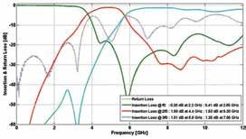
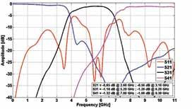
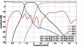
71 Typical Frequency Responses DP-1220 DP DP-1823 TP-1822 DP-2232 TP-2226 DP-2942 TP-2631 DP-3957 TP MAURY MICROWAVE CORPORATION 69


72 MT964 Load Pull Test Fixtures Low-Loss Test Fixtures For Load Pull and Other Power Applications Features > > Low Insertion Loss for High VSWR Tuning > > Multiple Connector Configurations > > 50W and Transformers Available > > Heatsinks and Fans Available > > Water Cooling Available > > Integrated Biasing Available MT964A1-50 7mm Load Pull Test Fixture Accessories Provided > > TRL Calibration Kit 1 Optional Accessories > > Water Cooling > > Device Inserts Available Models MT964A1-50 MT964A2-50 MT964A3-50 MT964C1-50 MT964C2-50 MT964C3-50 MT964C1-10 MT964C2-10 MT964C3-10 Frequency Range (GHz) W Impedance Connector 50 W 10 W 7mm 3.5mm 2.4mm 7mm 3.5mm 2.4mm 7mm 3.5mm 2.4mm Fixture Size Bias 950 mil No 2500 mil Optional 3 Power Handling W CW 25 W CW 250 W CW 25 W CW 250 W CW 25 W CW MT964C1-10 7mm Load Pull Test Fixture Dimensions (Inches) 1 Thru and Reflect standards built into fixture, external Line standard provided. 2 Proper heat dissipation of DUT is required. 3 Contact our Sales Staff for biasing option. See Maury Data Sheet 4T-005. MAURY MICROWAVE CORPORATION 70

73 Typical S21 Performance of MT964A1-50 Typical S11 Performance of MT964C1-10 MAURY MICROWAVE CORPORATION 71
 > > Re-configurable hardware; single-ended, differential and number of controlled harmonics > > High speed and dynamic range > > Embedded measurement of (Pulsed/Isothermal) DC parameters")
74 Mixed-Signal Active Load Pull System 1.0 MHz to 40.0 GHz Powered by Key Features (Typical Performance) > > Broadband system concept (e.g GHz) > > Re-configurable hardware; single-ended, differential and number of controlled harmonics > > High speed and dynamic range > > Embedded measurement of (Pulsed/Isothermal) DC parameters Single tone > > "Real-time" measurement speed >1,000 power and load states per minute > > Multi-dimensional parameter sweeps > > (Pulsed/Isothermal) High Power testing > > Measurement of calibrated Voltage and Current waveforms > > Device protection included > > Waveform reconstruction Modulated signals > > Wideband modulated signals (e.g. multi-carrier WCDMA) up to 240 MHz > > Modulated Signal Library Included > > Losses and delay of cables, probes etc. are eliminated > > Upload the s-parameters of any "virtual matching networks" and get a one-to-one agreement with your board design (also for linearity) > > Device testing with digital predistortion MAURY MICROWAVE CORPORATION 72


75 General Description This novel mixed-signal load pull system is designed to handle realistic wideband complex modulated signals with a high dynamic range and provide user defined reflection coefficients vs. frequency at the DUT reference planes. The system concept is based on: > > IQ signal generation, synthesized with fully synchronized arbitrary waveform generators (AWG) > > Wideband A/D converters to measure the wideband reflection coefficient Wideband Generation/Detection Figure 1. Principle of the Mixed-Signal Load Pull setup as a Signal-Flow diagram The maximum modulation bandwidth is set by the bandwidth of the AWG and IQ modulators. > > Currently more than 120 MHz of controlled bandwidth > > Total number of measurement points in every controlled band is >40,000 points "Real-Time" Load Pull Figure 2. Output spectrum of the DUT at f0 and 2f0 tested with multi-carrier WCDMA (with and without delay compensation). Synchronization between signal generation and detection facilitates ultra-fast measurements. > > Independently fully controlled multidimensional Load Pull parameters sweep > > 5,760 measurement points in less than 5 minutes: 90 fundamental load states, swept load and source harmonic termination, 16 power levels. Figure 3. Injection signals as used in the "real-time" multi-dimensional parameter sweeps. MAURY MICROWAVE CORPORATION 73

76 High Power/On-Wafer Configuration The active loops are fully re-configurable (e.g., the same hardware would also support source-pull at f0 and load-pull at f0, 2f0 and 3f0, or true differential source and load pull at f0). See [1] in the diagram below. The proprietary algorithm (patent pending) results in low requirements on the loop amplifiers, so linearity is no longer a problem in this regard, while their Psat should be just slightly larger than the power generated by the device under test (DUT). See [2] in the diagram below. [1] [2] Specifications System RF Bandwidth... See Available Models Table Modulation Bandwidth... See Available Models Table Typical Detection Dynamic Range db Active Load Dynamic Range db Minimum Pulse Width nsec MT2001 Software Modules > > MT2001A MT2000 POWER MEASUREMENTS (Required) > > MT2001B MT2000 MODULATED MEASUREMENTS > > MT2001C MT2000 TWO-TONE MEASUREMENTS > > MT2001D MT2000 NVNA (Time Domain Analysis) > > MT2001E EXTERNAL CONTROL > > MT2001F VISUALIZATION Suggested Reading > > 5A-044 Active Harmonic Load Pull with Realistic Wideband Communications Signals. > > 5A-045 Active Harmonic Load Pull for On-Wafer Outof- Band Device Linearity Optimization. > > 5A-046 A Mixed-Signal Approach for High-Speed Fully Controlled Multidimensional Load Pull Parameters Sweep. > > 5A-047 Base-Band Impedance Control and Calibration for On-Wafer Linearity Measurements. > > 5A-048 A Mixed-Signal Load Pull System for Base- Station Applications. > > 5C-087 Active Load Pull Surpasses 500 Watts! MAURY MICROWAVE CORPORATION 74
77 Available Models (MT2000) Model Modulation Bandwidth (MHz) MT2000HF MT2000HF MT2000HF MT2000HF MT2000HF MT2000HF MT2000A MT2000A MT2000A MT2000A MT2000A MT2000A MT2000B MT2000B MT2000B MT2000B MT2000B MT2000B MT2000D MT2000D MT2000D MT2000D MT2000D MT2000D MT2000E MT2000E MT2000E MT2000E MT2000E MT2000E Higher power options are available. System RF Bandwidth (GHz) Number of Active Tuning Loops Power 1 Handling: CW/Pulsed (W) 50/ / /200 Typical Detection Dynamic Range (db) 2 5-loop and 6-loop add-ons available. Typical Active Load Dynamic Range (db) Minimum Pulse Width (ns) Available Models (MT1000) Model System RF Bandwidth (GHz) Number of Active Tuning Loops 2 MT1000HF MT1000HF MT1000A MT1000A MT1000B MT1000B MT1000D MT1000D MT1000E MT1000E Higher power options are available. Power 1 Handling: CW/Pulsed (W) 50/ / /200 Typical Detection Dynamic Range (db) Typical Active Load Dynamic Range (db) Minimum Pulse Width (ns) loop and 6-loop add-ons available. MAURY MICROWAVE CORPORATION 75

78 Pulsed IV Systems AMCAD Engineering's PIV/PLP Family of Pulsed IV Systems AMCAD Engineering has created professional, industryproven pulsing technology for both standalone IV-testing as well as pulsed-bias load pull applications. Systems come fully equipped with a common 19 rack mountable mainframe controller that includes five integrated power supplies, output (drain/collector) and input (gate/base) remote pulser heads. Pulser heads are interchangeable and available in a range of models designed to fulfil PIV and Load Pull requirements. These include 15V/200mA, 120V/30A, 250V/10A and 100V/30A models. Each pulser head has its own embedded and integrated measurement unit. Key Features > > High-precision 200mA, High-power 10A or 30A pulse generation up to 1000V > > Pulse width down to 200ns > > Embedded measurement unit providing wide bandwidth & highly accurate simultaneous current and voltage measurements: Equivalent to 50M sample/s & 10 MHz bandwidth scope for pulse shape monitoring Fast averaging function providing 16 bit resolution & 0.1% typical measurement accuracy Very Fast Acquisition of a Complete Power Sweep to Speed Load Pull Test Benches > > Synchronized pulsed S-parameter measurements > > Embedded fast short-circuit current breaker protects both pulser heads (drain and gate) in the event of a DUT breakdown > > Pulse and measurement clocks are available in both standalone or external-triggered mode > > Remote control: GPIB or LAN > > Resistive network set provides for new device safe characterization > > High Voltage interconnects for 1000V Measurements > > MW/RF and power semiconductors These systems are specific Bilt systems dedicated to pulse operations, jointly developed by AMCAD Engineering and itest Corporation. MAURY MICROWAVE CORPORATION 76

79 Bilt System model BN106-AMCAD pulse I-V measurement system. Two Probe System Dedicated performance for PIV and Load Pull applications: Drain Voltage PIV Switching between Vds High and Vds Low. LOAD PULL Switching between OV and Vds High, or Fixed Vds with pulsed current Timing Fastest settling time for power pulse down to 200ns Smallest voltage drop for power pulse > 100µs Pulser Head Size Small dimensions, easy to connect Large storage capacitor inside the probe Measurement Accurate level monitoring and pulse shape monitoring External synchronisation available MAURY MICROWAVE CORPORATION 77

80 Gate Probe AM212 & AM213 Topology: Fast linear regulator. PARAMETER CONDITIONS MIN MAX Switched Voltage No Load 20V +20V Voltage Accuracy Typical 0.05% Switched Current Source or Sink 1A +1A Duty Cycle Including DC 0% 100% Rise & Fall Time At 95% 60ns 80ns Pulse Width 200ns AM212 Gate Pulsed Head Operating Area AM213 Drain Probe Topology: Switching Power Supply. AM221 PIV 10A AM222 PIV 30A AM223 PIV 200mA AM231 LP 10A AM232 LP 30A AM241 PIV 30A PARAMETER CONDITIONS MIN MAX MIN MAX MIN MAX MIN MAX MIN MAX MIN MAX High Level Switched Voltage No Current 0.0V 250V 0.0V 120V -5V +15V 0.0V 120V 0.0V 120V 0.0V 1000V Low Level Switched Voltage No Current 0.0V 120V 0.0V 120V -5V +15V 0.0V 120V 0.0V 120V 0.0V 120V Voltage Accuracy Typical 0.05% 0.05% 0.20% 0.05% 0.05% 0.5% Switched Current 10A 30A 200mA +200mA 10A 30A 30A RMS Current DC or Pulsed 3A 4A 0.2A 4A 4A 6A Output Impedance 0.5 W 0.15 W 10 W 0.08 W 0.05 W 1M W Pulsed Power 2kW 2kW 3W 1.2kW 3kW 3.6kW Average Pulsed Power 50W 50W 3W 50W 50W 90W Duty Cycle 0% 100% 0% 100% 0% 100% 0% 100% 0% 100% 0% 100% Pulse Width At Maximum Current 200ns 400ns 200ns 500ns 500ns 400ns Current Breaker Response Time 70ns 40ns 120ns 40ns 40ns 70ns 30A 4A 15A 3A 100 V 120 V 110V 1KV U MAURY MICROWAVE CORPORATION 78
81 Pulse Timing The switching working point is defined according to four programmable signals: Gate Switch, Drain Switch, RF Switch and Sample Clock. PARAMETER CONDITIONS SPECIFICATION MINIMUM MAXIMUM Time Resolution Any Outputs, Sampler, Duration and Delays 20ns Time Jitter Using External Synchronization Inputs ±2ns Pulse Frequency According to Power and Analog Limits 50Hz 500kHz Pulse Width According to Power and analog Limits 200ns 1ms Sample Frequency 50kHz Additional Specifications > > Time reference is available using both internal master clock and external signal. > > Measurement sampler clock is available using internal sequencer or external signal. > > The complemented level is available independently for each output. Continuous Signals Capability Although the system is primarily designed for pulsed testing, it is able to operate in continuous mode. > > Larger pulses are available using on/off continuous mode with a time resolution of 1ms. > > Pulsed or continuous operation modes are available independently for each output. MAURY MICROWAVE CORPORATION 79
82 Sampling Measurement Sampler Performances Thanks to a programmable measurement sampler, several acquisition modes are available, providing different levels of accuracy and speed: Pulse Shape Monitoring: Embedded Scope Onto Each Probe TYPICAL ABSOLUTE ACCURACY BANDWIDTH MAXIMUM SAMPLING RATE RIPPLE MEASUREMENT WINDOW 1.0% During a Transition 0.1% Within a Pulse 10 MHz 50 MHz 0.2% 250 Samples Accurate Working Point measurement Within a Pulse Using Fast Averaging Function RESOLUTION TYPICAL ABSOLUTE ACCURACY MINIMUM SETTLING TIME WITHIN THE PULSE RIPPLE 16 Bits 0.1% 200ns 0,003% Power Sweep Monitoring: Accurate Working Point Measurement for Each Step of the Sweep TYPICAL ABSOLUTE MINIMUM SETTLING TIME TOTAL STEP TIME INCLUDING SETTLING RESOLUTION RIPPLE ACCURACY WITHIN THE PULSE & MEASUREMENT 16 Bits 0.1% 200ns 0,003% 100ms in any case, the four inputs (Vg, Ig, Vd, Id) are sampled at the same time, and the data buffers can be read at once. Guaranteed Absolute Accuracy Versus Ranges: The gate probe uses bipolar ranges, while the two drain probes use only positive ranges. For the purpose of increasing small amplitude accuracy, a one-tenth range is available at any time, without switching the outputs. GATE PULSER HEAD DRAIN 10A PIV PULSER HEAD DRAIN 30A PIV PULSER HEAD VOLTAGE CURRENT VOLTAGE CURRENT VOLTAGE CURRENT RANGE ±15V ±20mA ±0.2A 25V 250V 1A 10A 12V 120V 3A 30A ACCURACY 30mA 40µA 400µA 50mV 550mV 2mA 20mA 25V 250V 6mA 120mA MAURY MICROWAVE CORPORATION 80

83 RF Device Characterization System Integration Fully Integrated Coaxial and Millimeter-Wave Device Characterization Systems, 250 MHz to 110 GHz Features > > Power and noise parameter measurements > > Packaged and On-Wafer measurements > > Modulated, pulsed and CW signals > > Automated in-situ calibration > > Fewer connections > > Reliable and fast RF switching > > Saves time and money > > Turnkey systems available Works out of the box Description Maury s mission is to meet its customers device characterization needs regardless of the level of complexity. Maury has and continues to provide solutions covering the entire measurement spectrum; from the simplest stand-alone tuner to fully integrated turnkey systems. Integrated systems are offered between 250 MHz and 110 GHz, in-fixture and on-wafer, and are capable of measuring the following: > > S-Parameters > > X-Parameters > > DC-IV and Pulsed-IV measurements > > Power Measurements: Pout, Pin-delivered, Gain, Compression, Efficiency, Harmonic Powers > > Multi-Tone Measurements: IMD, TOI > > Modulated Measurements: ACPR, EVM, CCDF > > Noise Parameters: NFmin, Γopt, Rn, Noise and Gain contours > > Time-domain Analysis: A-B waves, I-V waves, load lines > > Thermal Microscopic load pull Maury will integrate these features into an easily assembled and calibrated system that is straightforward to use, saving time as well as money. Furthermore, the results will display greater accuracy and repeatability. Less time and less money means a more profitable design cycle. In-situ Calibration The power of a Maury integrated system begins with its proprietary in-situ calibration method, which allows for a complete system-level calibration without disconnecting any of the core system components. The majority of calibration and measurement errors occur for the following reasons; multiple VNA calibrations with improper reference-plane shifting, MT900N Series Fully Integrated 2.4mm 50 GHz LSNA Measurement System. probes that are connected/disconnected multiple times or measured on their own, and multiple small measurement errors that cascade into very large errors. Unlike the above situations, in-situ calibration requires only one single connection, makes use of highly-repeatable and reliable RF switches and automates the calibration procedure through the use of a graphic wizard. Overall system level verification procedures built into the ATS software result in average deltagt values of less than 0.2 db at all magnitudes and phases, when performing an in-situ calibration. Turnkey Measurement Systems Maury works very closely with instrument and component manufacturers to offer complete turnkey noise parameters as well as large-signal test systems for both on-wafer and packaged device measurements. Recognized as the global leader in microwave and millimeter-wave tuners and DC systems, Maury has partnered with numerous multinational companies who are also leaders in their respective fields. Examples include Keysight Technologies for RF Instruments (Network Analyzers, Spectrum Analyzers, Power meters, Power supplies), Cascade Microtech (on-wafer probe stations, probes and positioners), Intercontinental Microwave (test fixtures and jigs), Quantum Focus Instruments (Thermal IR cameras), Auriga Measurement Systems (Pulsed IV), as well as component and cabling manufacturers. Turnkey measurement systems are available for sign-off and acceptance at Maury s corporate office. MAURY MICROWAVE CORPORATION 81


84 MT900-series integrated on-wafer millimeter-wave s-parameters, noise parameters and load pull system, including swept two-tone measurements. MT900-series integrated on-wafer millimeter-wave s-parameters, noise parameters and load pull measurement system. Key Literature: Application Note 5A-039. MAURY MICROWAVE CORPORATION 82
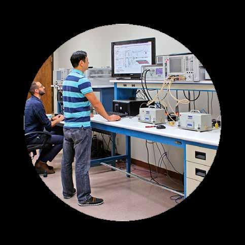


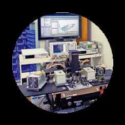
85 Measurement and Modeling Device Characterization Services MAURY MICROWAVE CORPORATION 83

86 Why Measurement Services? Maury s team of experienced application engineers operates its state-of-the-art characterization laboratories to provide timesensitive measurement services each and every day. Maury customers have taken advantage of our expertise and resources to meet their objectives on time and on budget. Some of the reasons our customers work with us include: completing short term or infrequent projects, eliminating bottlenecks and accelerating delivery by working in parallel, validating in-house measurements, establishing proof of concept and system justification, always using state-of-the-art tools, reducing capital expenditures and improving the balance sheet. We are better suited to meet our customers needs due to the flexibility associated with measurement and modeling device characterization services. Scenario 1: Short-term or project-specific need Tom has been mandated to design an applicationspecific amplifier which will be integrated into his company s next-generation transceiver. Since Tom s projects each have unique requirements, Tom has not been able to acquire his own load pull system, let alone the periphery instruments required to integrate the solution or the experience required to operate the system efficiently. Tom takes advantage of Maury s experience and resources by executing a measurement service and is able to complete his project without the investment in capital equipment. Scenario 2: System proof-of-concept and justification John believes a noise parameter measurement system would improve his overall low-noise amplifier development time by validating his models, and allowing him to make refinements on an ongoing basis. Before making the investment in capital equipment, John contracts a measurement service and receives a complete set of measurement results as a deliverable. With data in hand, John proves he is able to improve his LNA design flow and feels secure in acquiring his own system. Lab Equipment* > > Network analyzers: Keysight N5242A, N5245A, N5247A > > Signal sources: Keysight N5181A, N5183A, E4438C > > Signal analyzers: Keysight N9010A, N5242A/N5245A/ N5247A, NI 5644R, Maury Microwave MT2000E4-120 > > Noise analyzers: Keysight N8975A, N5242A/N5245A/ N5247A with option 029 > > Power meters: Keysight N1911A, E4416A, E4417A, E4418B, E4419B, U2002A, and power sensors > > IV analyzers: AMCAD Engineering AMBILT pulsed IV system > > Oscilloscopes: Keysight DSO7104A, DSO1024A and probes > > Probe stations: Cascade Summit 9000 manual, Summit 11K manual, Summit 12K semi-automatic > > Impedance tuners: multiple Maury Microwave MT981BL01, MT982BL01, MT984AL01, MT2000E4-120 > > Miscellaneous: DC and RF accessories * Equipment list accurate at date of print Scenario 3: Eliminating bottleneck and accelerating delivery Lisa is responsible for technology selection at her company and is in the process of evaluating multiple device topologies. With Lisa s deadline to report her findings approaching quickly, Lisa knows she will not be able to complete her evaluation within the allotted time period. Lisa outsources a portion of her measurements in order to increase her effective measurement capacity and is therefore able to complete all measurements, and compile her report with recommendations, in time. MAURY MICROWAVE CORPORATION 84
87 Services Offered Measurement Parameters Measurement Capability DC and Pulsed IV Measurements Fixed and swept voltages and currents for ld, lg, Vd, Vg and computation of gm On-wafer and in-fixture DC and Pulsed IV characterization up to 1000V and 30A CW and Pulsed S-Parameter Two-port S-parameter (S11, S12, S21, S22) characterization at user-defined reference plane On-wafer and in-fixture CW and pulsed-cw S-parameter measurements between 10 MHz and 67 GHz Noise Figure/ Parameters Measurements Noise figure: NF50 Noise parameters: NF50, NFmin, Γopt, Rn, noise circles (typical noise measurements performed in screen room / Faraday cage) On-wafer and in-fixture measurements Noise figure 10 MHz to 50 GHz Noise parameters 400 MHz to 67 GHz Power Measurements- CW/Pulsed-CW Signal Power parameters including available and delivered input power (Pin), delivered output power (Pout) at individual frequencies, transducer and power gain, power-added and drain efficiency, intermodulation distortion products (IMD, if applicable) On-wafer and in-fixture power measurements between 10 MHz and 67 GHz CW and pulsed-cw, single-tone and two-tone RF signal DC and pulsed bias conditions Fixed and swept impedance at fundamental and harmonic frequencies Power Measurements- Modulated Signal In addition to power parameters above, modulated parameters including adjacent channel power/leakage (ACLR/ACPR) and error vector magnitude (EVM) On-wafer and in-fixture power measurements between 400 MHz and 40 GHz using commercial and user-defined modulated signal Power Measurements- Nonlinear VNA (NVNA) In addition to power parameters above, nonlinear time-domain current and voltage waveforms and RF load lines On-wafer and in-fixture power measurements between 400 MHz and 40 GHz Please contact us to explore how Maury can support your measurement and modeling needs. MAURY MICROWAVE CORPORATION 85


88 Sample Measurements Visualization of output power vs PAE at fixed 3dB gain compression Power sweep at multiple impedances Impedance sweep at fixed power Output current waveforms at constant input power under varying load impedances MAURY MICROWAVE CORPORATION 86


89 Sample Measurements Continued DC and RF load lines at constant input power under varying load impedances IV curves at various wafer positions Broadband swept noise parameters Active load pull of multi-channel LTE signal MAURY MICROWAVE CORPORATION 87
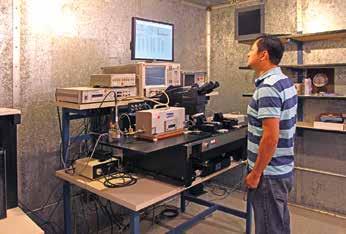
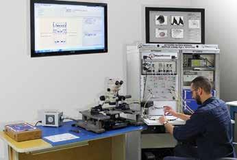
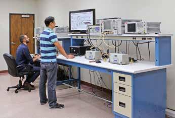
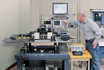
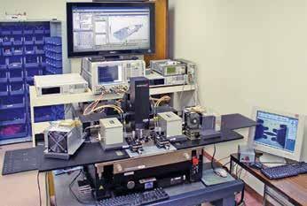

90 Measurement and Modeling Device Characterization Facilities MAURY MICROWAVE CORPORATION 88

91 Some Tuners Just Work Better Than Others Maury Tuners Work Better Because They Are Built Better! Maury Technology Makes The Difference: 1. Optical Limit Switches at Both Ends of Each Movement for Optimum Accuracy and Repeatability 2. Non-Contacting Mismatch Probes never Touch the Center Conductor for Increased Reliability and Longevity 3. Precision Machined Connectors and a Wide Range of Precision Adapters Makes Setup Easy 4. Precision Machined Slablines (Developed by Maury s Material Science Division) ensure Repeatability and Increase Accuracy 5. High Peak Power Breakdown Protection Provides Increased Reliability and Stability 6. High DC current Rating 7. LXI -Certified Embedded Tuner Controller

92
Precision Calibration & Interconnect Solutions
 ALSO AVAILABLE FROM MAURY MICROWAVE Precision Calibration & Interconnect Solutions Maury Precision VNA Calibration Kits For Fixed Load, Sliding Load and TRL Calibration of Keysight, Rhode & Schwarz and
Measurement & Modeling Device Characterization Solutions
 Also Available from Maury Microwave Measurement & Modeling Device Characterization Solutions Featuring The Most Complete Selection of Load Pull Solutions in the Test & Measurement Industry Helping Your
Microwave & RF Device Characterization Solutions
 Microwave & RF Device Characterization Solutions MT2000 Mixed-Signal Active Load Pull System (1.0 MHz to 40.0 GHz) And MT2001 System Software From Powered by Maury Microwave is ISO: 9001:2008/AS9100C Certified.
Measurement & Modeling Device Characterization Solutions
 ALSO AVAILABLE FROM MAURY MICROWAVE Measurement & Modeling Device Characterization Solutions Featuring The Most Complete Selection of Load Pull Solutions in the Test & Measurement Industry Helping Your
IVCAD Advanced Measurement & Modeling Software
 IVCAD Advanced Measurement & Modeling Software DATA SHEET / 4T-022 IVCAD SOFTWARE SUITE MODULES: MT930B1 IVCAD Basic Visualization MT930B2 IVCAD Advanced Visualization Add-On MT930C IVCAD Vector-Receiver
Measurement & Modeling Device Characterization Solutions
 ALSO AVAILABLE FROM MAURY MICROWAVE Measurement & Modeling Device Characterization Solutions Featuring The Most Complete Selection of Load Pull Solutions in the Test & Measurement Industry. Helping Your
X-Parameters with Active and Hybrid Active Load Pull
 X-Parameters with Active and Hybrid Active Load Pull Gary Simpson, CTO Maury Microwave EuMW 2012 www.maurymw.com 1 General Load Pull Overview 2 Outline 1. Introduction to Maury Microwave 2. Basics and
LXI High-Gamma Automated Tuners (HGT ) And LXI High-Power Automated Tuners
 And LXI High-Power Automated Tuners") LXI High-Gamma Automated Tuners (HGT ) And LXI High-Power Automated Tuners DATA SHEET / T-050G0 MODELS: MT98HL MT98HL MT98HL5 MT98AL MT98BL5 MT98BL0 MT98BL8 MT98WL0 MT98VL0 MT98EL0 // MARCH 08 What is
LXI High-Gamma Automated Tuners (HGT ) And LXI High-Power Automated Tuners DATA SHEET / T-050G0 MODELS: MT98HL MT98HL MT98HL5 MT98AL MT98BL5 MT98BL0 MT98BL8 MT98WL0 MT98VL0 MT98EL0 // MARCH 08 What is
MT1000 and MT2000 Mixed-Signal Active Load Pull System (1.0 MHz to 40.0 GHz) And MT2001 System Software
 And MT2001 System Software") MT1000 and MT0 Mixed-Signal Active Load Pull System (1.0 MHz to 40.0 GHz) And MT1 System Software DATA SHEET / 4T-097 U.S. Patent No. 8,456,175 B2 Several international patents also available // SEPTEMBER
MT1000 and MT0 Mixed-Signal Active Load Pull System (1.0 MHz to 40.0 GHz) And MT1 System Software DATA SHEET / 4T-097 U.S. Patent No. 8,456,175 B2 Several international patents also available // SEPTEMBER
LXI -Certified 3.5mm Automated Tuners
 LXI -Certified 3.5mm Automated Tuners DATA SHEET / 4T-050G08 MODELS: XT983BL01 XT-SERIES TUNERS REPRESENT THE NEXT EVOLUTION IN TUNER TECHNOLOGY. FASTER, MORE ACCURATE, MORE REPEATABLE. Products covered
LXI -Certified 7mm Automated Tuners
 LXI -Certified 7mm Automated Tuners DATA SHEET / 4T-050G02 MODELS: MT982GL01 MT982GL30 MT982BL01 MT982EL30 MT982AL02 // JANUARY 2018 What is load pull? Load Pull is the act of presenting a set of controlled
LXI -Certified 3.5mm, 2.4mm & 1.85mm Automated Tuners
 LXI -Certified 3.5mm, 2.4mm & 1.85mm Automated Tuners DATA SHEET / 4T-050G04 MODELS: MT983BL01 MT984AL01 MT985AL01 // JANUARY 2018 What is load pull? Load Pull is the act of presenting a set of controlled
LXI -Certified 7mm Automated Tuners
 LXI -Certified 7mm Automated Tuners DATA SHEET / 4T-050G07 MODELS: XT982GL01 XT982GL30 XT982AL02 XT-SERIES TUNERS REPRESENT THE NEXT EVOLUTION IN TUNER TECHNOLOGY. FASTER, MORE ACCURATE, MORE REPEATABLE.
LXI High-Gamma Automated Tuners (HGT ) And LXI High-Power Automated Tuners
 And LXI High-Power Automated Tuners") LXI High-Gamma Automated Tuners (HGT ) And LXI High-Power Automated Tuners DATA SHEET / T-050G06 MODELS: XT98HL XT98HL XT98HL5 XT98AL XT98BL0 XT98BL8 XT98VL0 XT-SERIES TUNERS REPRESENT THE NEXT EVOLUTION
LXI High-Gamma Automated Tuners (HGT ) And LXI High-Power Automated Tuners DATA SHEET / T-050G06 MODELS: XT98HL XT98HL XT98HL5 XT98AL XT98BL0 XT98BL8 XT98VL0 XT-SERIES TUNERS REPRESENT THE NEXT EVOLUTION
LXI -Certified 2.4mm & 1.85mm Automated Tuners
 LXI -Certified 2.4mm & 1.85mm Automated Tuners DATA SHEET / 4T-050G04A MODELS: MT984AL01 MT985AL01 // JUNE 2018 What is load pull? Load Pull is the act of presenting a set of controlled impedances to a
Vector-Receiver Load Pull Measurement
 MAURY MICROWAVE CORPORATION Vector-Receiver Load Pull Measurement Article Reprint of the Special Report first published in The Microwave Journal February 2011 issue. Reprinted with permission. Author:
LXI -Certified Multi-Harmonic Automated Tuners
 LXI -Certified Multi-Harmonic Automated Tuners DATA SHEET / 4T-050G03 MODELS: MT981ML01 MT982ML01 MT983ML01 // JANUARY 2018 What is load pull? Load Pull is the act of presenting a set of controlled impedances
Keysight Technologies Nonlinear Vector Network Analyzer (NVNA) Breakthrough technology for nonlinear vector network analysis from 10 MHz to 67 GHz
 Breakthrough technology for nonlinear vector network analysis from 10 MHz to 67 GHz") Keysight Technologies Nonlinear Vector Network Analyzer (NVNA) Breakthrough technology for nonlinear vector network analysis from 1 MHz to 67 GHz 2 Keysight Nonlinear Vector Network Analyzer (NVNA) - Brochure
Keysight Technologies Nonlinear Vector Network Analyzer (NVNA) Breakthrough technology for nonlinear vector network analysis from 1 MHz to 67 GHz 2 Keysight Nonlinear Vector Network Analyzer (NVNA) - Brochure
PNA Family Microwave Network Analyzers (N522x/3x/4xB) CONFIGURATION GUIDE
 CONFIGURATION GUIDE") PNA Family Microwave Network Analyzers (N522x/3x/4xB) CONFIGURATION GUIDE Table of Contents PNA Family Network Analyzer Configurations... 05 Test set and power configuration options...05 Hardware options...
PNA Family Microwave Network Analyzers (N522x/3x/4xB) CONFIGURATION GUIDE Table of Contents PNA Family Network Analyzer Configurations... 05 Test set and power configuration options...05 Hardware options...
Pulse IV and pulsed S-parameter Parametric Analysis with AMCAD PIV & AGILENT PNA-X
 Pulse IV and pulsed S-parameter Parametric Analysis with AMCAD PIV & AGILENT PNA-X Tony Gasseling gasseling@amcad-engineering.com 1 Components PA Design Flow Measurement system Measurement Data base Circuits
New Ultra-Fast Noise Parameter System... Opening A New Realm of Possibilities in Noise Characterization
 New Ultra-Fast Noise Parameter System... Opening A New Realm of Possibilities in Noise Characterization David Ballo Application Development Engineer Agilent Technologies Gary Simpson Chief Technology Officer
Load Pull with X-Parameters A New Paradigm for Modeling and Design
 Load Pull with X-Parameters A New Paradigm for Modeling and Design Gary Simpson, CTO Maury Microwave Anaheim, May 2010 For a more detailed version of this presentation, go to www.maurymw.com/presentation.htm
Type N Coaxial Calibration Kit
 User Guide Type N Coaxial Calibration Kit DC to 18 GHz Model 8850CK30/31 8850-531 (A) 3/15 User Guide Type N Coaxial Calibration Kit DC to 18 GHz Model 8850CK30/31 2900 Inland Empire Boulevard Ontario,
USER GUIDE 2.92mm Coaxial Calibration Kit
 USER GUIDE 2.92mm Coaxial Calibration Kit DC to 40 GHz Model 8770CK30/31 8770-532 (A) 03/16 USER GUIDE 2.92mm Coaxial Calibration Kit DC to 40 GHz Model: 8770CK30/31 Please note: This manual applies to
Integrated, Turnkey Modeling and Measurement Systems
 Integrated, Turnkey Modeling and Measurement Systems Cover Feature Invited Papers From Keysight Technologies National Instruments Maury Microwave Focus Microwaves Editor s Note: As time-to-market demands
print close Chris Bean, AWR Group, NI
 1 of 12 3/28/2016 2:42 PM print close Microwaves and RF Chris Bean, AWR Group, NI Mon, 2016-03-28 10:44 The latest version of an EDA software tool works directly with device load-pull data to develop the
USER GUIDE. WR284 Waveguide TRL Calibration Kit GHz. Models: WR284C30\32 Series (Rev A) 03/16
 03/16") USER GUIDE WR284 Waveguide TRL Calibration Kit 2.60 3.95 GHz Models: WR284C30\32 Series 8770-512 (Rev A) 03/16 USER GUIDE WR284 Waveguide TRL Calibration Kit 2.60 3.95 GHz Models: WR284C30\32 Series Warranty
USER GUIDE WR284 Waveguide TRL Calibration Kit 2.60 3.95 GHz Models: WR284C30\32 Series 8770-512 (Rev A) 03/16 USER GUIDE WR284 Waveguide TRL Calibration Kit 2.60 3.95 GHz Models: WR284C30\32 Series Warranty
Vector Network Analyzer
 Vector Network Analyzer VNA Basics VNA Roadshow Budapest 17/05/2016 Content Why Users Need VNAs VNA Terminology System Architecture Key Components Basic Measurements Calibration Methods Accuracy and Uncertainty
A Comparison of Harmonic Tuning Methods for Load Pull Systems
 MAURY MICROWAVE CORPORATION A Comparison of Harmonic Tuning Methods for Load Pull Systems Author: Gary Simpson, MSEE Director of Technical Development in Engineering, Maury Microwave Corporation July 2009
Agilent Technologies Gli analizzatori di reti della serie-x
 Agilent Technologies Gli analizzatori di reti della serie-x Luigi Fratini 1 Introducing the PNA-X Performance Network Analyzer For Active Device Test 500 GHz & beyond! 325 GHz 110 GHz 67 GHz 50 GHz 43.5
Agilent Nonlinear Vector Network Analyzer (NVNA)
") Agilent Nonlinear Vector Network Analyzer (NVNA) Breakthrough technology for nonlinear vector network analysis from 1 MHz to 67 GHz I know my amplifier gain is changing with output match, but Hot S22 measurements
Agilent Nonlinear Vector Network Analyzer (NVNA) Breakthrough technology for nonlinear vector network analysis from 1 MHz to 67 GHz I know my amplifier gain is changing with output match, but Hot S22 measurements
IVCAD VNA Base Load Pull with Active/Hybrid Tuning. Getting Started v3.5
 IVCAD VNA Base Load Pull with Active/Hybrid Tuning Getting Started v3.5 1 Setting and Configuration Block Diagram... 3 1.1 VNA setup... 5 1.2 RF source setup... 6 1.3 Power meter setup... 7 1.4 Source
Configuration of PNA-X, NVNA and X parameters
 Configuration of PNA-X, NVNA and X parameters VNA 1. S-Parameter Measurements 2. Harmonic Measurements NVNA 3. X-Parameter Measurements Introducing the PNA-X 50 GHz 43.5 GHz 26.5 GHz 13.5 GHz PNA-X Agilent
Advanced Test Equipment Rentals ATEC (2832) Agilent 8510 System Solutions
 Agilent 8510 System Solutions") E stablished 1981 Advanced Test Equipment Rentals www.atecorp.com 800-404-ATEC (2832) Agilent 8510 System Solutions Your bridge to the future Application guide The guide below shows Agilent Technologies
E stablished 1981 Advanced Test Equipment Rentals www.atecorp.com 800-404-ATEC (2832) Agilent 8510 System Solutions Your bridge to the future Application guide The guide below shows Agilent Technologies
AU4850 Pulsed IV/RF Characterization System
 FOURTH GENERATION PULSED IV/RF Featuring 220 V, 30 A with 0.01% Current Resolution for RF designers S-parameter Option for Major Network Analyzers Pulsed Load-pull Option 1200 V, 30 A with Enhanced ON-resistance
Hot S 22 and Hot K-factor Measurements
 Application Note Hot S 22 and Hot K-factor Measurements Scorpion db S Parameter Smith Chart.5 2 1 Normal S 22.2 Normal S 22 5 0 Hot S 22 Hot S 22 -.2-5 875 MHz 975 MHz -.5-2 To Receiver -.1 DUT Main Drive
Large-Signal Network Analysis Technology for HF analogue and fast switching components
 Large-Signal Network Analysis Technology for HF analogue and fast switching components Applications This slide set introduces the large-signal network analysis technology applied to high-frequency components.
RF and Microwave Test and Design Roadshow 5 Locations across Australia and New Zealand
 RF and Microwave Test and Design Roadshow 5 Locations across Australia and New Zealand Advanced VNA Measurements Agenda Overview of the PXIe-5632 Architecture SW Experience Overview of VNA Calibration
Load Pull Validation of Large Signal Cree GaN Field Effect Transistor (FET) Model
 Model") APPLICATION NOTE Load Pull Validation of Large Signal Cree GaN Field Effect Transistor (FET) Model Introduction Large signal models for RF power transistors, if matched well with measured performance,
APPLICATION NOTE Load Pull Validation of Large Signal Cree GaN Field Effect Transistor (FET) Model Introduction Large signal models for RF power transistors, if matched well with measured performance,
Lightning D Vector Network Analyzers. Network Analysis Solutions for Design and Manufacturing. 40 MHz to 65 GHz
 Lightning 37000D Vector Network Analyzers 40 MHz to 65 GHz Network Analysis Solutions for Design and Manufacturing Vector Network Analyzers that offer... The 37000D Lightning Vector Network Analyzers are
Test & Measurement Instrument Amplifiers
 Test & Measurement Instrument Amplifiers DATA SHEET / 4T-101 MODELS: MPA-0G7-6G-16 MPA-0G7-6G-50 MPA-2G-6G-20 MPA-2G-6G-50 MPA-2G-18G-16 MPA-2G-18G-30 MPA-6G-18G-5 MPA-6G-18G-20 MPA-6G-18G-50 MPA-8G-12G-30
Vector Network Analysis
 Portfolio Brochure Vector Network Analysis Product Portfolio Vector Network Analysis VNA Innovation Timeline In 1965, Anritsu filed the patent that defined the first modern Vector Network Analyzer (VNA).
A New Noise Parameter Measurement Method Results in More than 100x Speed Improvement and Enhanced Measurement Accuracy
 MAURY MICROWAVE CORPORATION March 2013 A New Noise Parameter Measurement Method Results in More than 100x Speed Improvement and Enhanced Measurement Accuracy Gary Simpson 1, David Ballo 2, Joel Dunsmore
How do I optimize desired Amplifier Specifications?
 How do I optimize desired Amplifier Specifications? PAE (accuracy
Agilent 86030A 50 GHz Lightwave Component Analyzer Product Overview
 Agilent 86030A 50 GHz Lightwave Component Analyzer Product Overview 2 Characterize 40 Gb/s optical components Modern lightwave transmission systems require accurate and repeatable characterization of their
Agilent Upgrade Guide for the 8510 Vector Network Analyzer Product Note
 Agilent Upgrade Guide for the 8510 Vector Network Analyzer Product Note 85107B, 45 MHz to 50 GHz in coax 85106D with option 001, 45 MHz to 50 GHz in coax, above 50 GHz in waveguide 8510XF on-wafer configuration
5 ESSENTIAL HINTS TO IMPROVE Millimeter-wave Network Analysis
 5 ESSENTIAL HINTS TO IMPROVE Millimeter-wave Network Analysis Contents 5 Essential Hints to Improve Millimeter-wave Network Analysis Ensure Accurate, Repeatable Results Go to Hint 1 > Calibrate for Better
Noise Calibration Systems and Accessories DATA SHEET / 4N-062
 Noise Calibration Systems and Accessories DATA SHEET / 4N-062 // MARCH 2018 Noise Calibration Systems and Components MT7149J99 WR10 75 110 GHz Noise Calibration System Introduction The Maury Noise Calibration
Focus Microwaves Inc. 970 Montee de Liesse, Ste. 308 Ville St-Laurent, Quebec H4T-1W7, Canada Tel Fax
 Focus Microwaves Inc. 970 Montee de Liesse, Ste. 308 Ville St-Laurent, Quebec H4T-1W7, Canada Tel 514-335-6227 Fax 514-335-6287 Product Note No 12A Measurement Software for the Computer Controlled Microwave
Keysight Technologies Making Accurate Intermodulation Distortion Measurements with the PNA-X Network Analyzer, 10 MHz to 26.5 GHz
 Keysight Technologies Making Accurate Intermodulation Distortion Measurements with the PNA-X Network Analyzer, 10 MHz to 26.5 GHz Application Note Overview This application note describes accuracy considerations
2005 Modelithics Inc.
 Precision Measurements and Models You Trust Modelithics, Inc. Solutions for RF Board and Module Designers Introduction Modelithics delivers products and services to serve one goal accelerating RF/microwave
Wide Matching Range Slide Screw Tuners DATA SHEET / 2G-035
 Wide Matching Range Slide Screw Tuners DATA SHEET / 2G-035 // JANUARY 2018 Wide Matching Range Slide Screw Tuners SERIES MST981, MST982, MST983 & MST984 MST982E35 Features > > Slab-line Transmission Structure
Using Enhanced Load-Pull Measurements for the Design of Base Station Power Amplifiers
 Application Note Using Enhanced Load-Pull Measurements for the Design of Base Station Power Amplifiers Overview Load-pull simulation is a very simple yet powerful concept in which the load or source impedance
Nonlinear Characterization and Modeling Through Pulsed IV/S-Parameters
 Nonlinear Characterization and Modeling Through Pulsed IV/S-Parameters OUTLINE Introduction Core device model extraction Model Enhancement Model Validation Types of Large-Signal Transistor Models Convergence
Keysight Technologies Amplifier and CW Swept Intermodulation - Distortion Measurements using the PNA Microwave Network Analyzers.
 Keysight Technologies Amplifier and CW Swept Intermodulation - Distortion Measurements using the PNA Microwave Network Analyzers Application Note Introduction This application note covers testing of an
MEASUREMENT OF LARGE SIGNAL DEVICE INPUT IMPEDANCE DURING LOAD PULL
 Model M956D CORPORAION MEASUREMEN OF LARGE SIGNAL DEVICE INPU IMPEDANCE DURING LOAD PULL Abstract Knowledge of device input impedance as a function of power level and load matching is useful to fully understand
Platform Migration 8510 to PNA. Graham Payne Application Engineer Agilent Technologies
 Platform Migration 8510 to PNA Graham Payne Application Engineer Agilent Technologies We set the standard... 8410 8510 When we introduced the 8510, we changed the way S-parameter measurements were made!
A Simulation-Based Flow for Broadband GaN Power Amplifier Design
 Rubriken Application A Simulation-Based Flow for Broadband GaN Power Amplifier Design This application note demonstrates a simulation-based methodology for broadband power amplifier (PA) design using load-line,
Frequency Response Analyzers for Stability Analysis and Power Electronics Performance Testing
 Frequency Response Analyzers for Stability Analysis and Power Electronics Performance Testing Product Features Since 1979, Venable Instruments has been focused on one goal: bringing the most versatile,
Tour Agilent ADS EMPro 2011 Stability Analysis of Microwave Circuits
 Tour Agilent ADS EMPro 2011 Stability Analysis of Microwave Circuits S. Dellier, PhD AMCAD Engineering Introduction to AMCAD s products and services AMCAD is a provider of new RF & Microwave solutions
Compact Series: S5065 & S5085 Vector Network Analyzers KEY FEATURES
 Compact Series: S5065 & S5085 Vector Network Analyzers KEY FEATURES Frequency range: 9 khz - 6.5 or 8.5 GHz Measured parameters: S11, S12, S21, S22 Wide output power adjustment range: -50 dbm to +5 dbm
Cascading Tuners For High-VSWR And Harmonic Load Pull
 Cascading Tuners For High-VSWR And Harmonic Load Pull Authors: Steve Dudkiewicz and Roman Meierer, Maury Microwave Corporation ABSTRACT: For the first time ever, two or three tuners can be cascaded externally
RF & Microwave Amplifiers to 20GHz
 RF & Microwave Amplifiers to 20GHz Short form Catalog EuMW 2013 Low-Noise & Small Signal Power Amplifiers High Energy Physics Wideband GaN ECM Digital TV IMD Testing General Purpose Wideband Particle Physics,
MACRO FILE AND DESIGN WINDOW COMPRESSION LOAD PULL MEASUREMENTS
 TECHNICAL FEATURE MACRO FILE AND DESIGN WINDOW COMPRESSION LOAD PULL MEASUREMENTS This article describes measurement and evaluation algorithms that allow full load pull tests to be performed while drining
Keysight Technologies Vector Network Analyzer Receiver Dynamic Accuracy
 Specifications and Uncertainties Keysight Technologies Vector Network Analyzer Receiver Dynamic Accuracy (Linearity Over Its Specified Dynamic Range) Notices Keysight Technologies, Inc. 2011-2016 No part
ME7220A. Radar Test System (RTS) Target Simulation & Signal Analysis for Automotive Radar Exceptional Performance at an Affordable Price.
 Target Simulation & Signal Analysis for Automotive Radar Exceptional Performance at an Affordable Price.") ME7220A Test System (RTS) 76 to 77 GHz Target Simulation & Signal Analysis for Automotive Exceptional Performance at an Affordable Price The Challenge The installation of collision warning and Adaptive
ME7220A Test System (RTS) 76 to 77 GHz Target Simulation & Signal Analysis for Automotive Exceptional Performance at an Affordable Price The Challenge The installation of collision warning and Adaptive
New LDMOS Model Delivers Powerful Transistor Library Part 1: The CMC Model
 From October 2004 High Frequency Electronics Copyright 2004, Summit Technical Media, LLC New LDMOS Model Delivers Powerful Transistor Library Part 1: The CMC Model W. Curtice, W.R. Curtice Consulting;
Agilent N5250A PNA Millimeter-Wave Network Analyzer 10 MHz to 110 GHz
 Agilent N5250A PNA Millimeter-Wave Network Analyzer 10 MHz to 110 GHz Technical Overview High Performance Bench-Top Network Analyzer Maximize your frequency coverage with a single sweep from 10 MHz to
DESIGN OF AN ULTRA-EFFICIENT GAN HIGH POWER AMPLIFIER FOR RADAR FRONT-ENDS USING ACTIVE HARMONIC LOAD-PULL
 DESIGN OF AN ULTRA-EFFICIENT GAN HIGH POWER AMPLIFIER FOR RADAR FRONT-ENDS USING ACTIVE HARMONIC LOAD-PULL Tushar Thrivikraman, James Hoffman Jet Propulsion Laboratory, California Institute of Technology
Analyzing Device Behavior at the Current Generator Plane of an Envelope Tracking Power Amplifier in a High Efficiency Mode
 Analyzing Device Behavior at the Current Generator Plane of an Envelope Tracking Power Amplifier in a High Efficiency Mode Z. Mokhti, P.J. Tasker and J. Lees Centre for High Frequency Engineering, Cardiff
A compact and versatile test solution that accurately simulates real life
 UHF L S C X Ku K Product Frequency Range Ka AU4850 A compact and versatile test solution that accurately simulates real life Auriga s 4th generation pulsed IV/RF characterization system delivers unparalleled
GT-1050A 2 GHz to 50 GHz Microwave Power Amplifier
 Established 1981 Advanced Test Equipment Rentals www.atecorp.com 800-404-ATEC (2832) Giga-tronics GT-1050A Microwave Power Amplifier GT-1050A 2 GHz to 50 GHz Microwave Power Amplifier Operation Manual
Vector Network Analyzer Application note
 Vector Network Analyzer Application note Version 1.0 Vector Network Analyzer Introduction A vector network analyzer is used to measure the performance of circuits or networks such as amplifiers, filters,
Agilent PNA-X Series Microwave Network Analyzers
 Agilent PNA-X Series Microwave Network Analyzers Reach for unrivaled excellence 1 Choose the leader in network analysis Industry s Most Advanced RF Test Solution Reach for unrivaled excellence The PNA-X
Measurements with Scattering Parameter By Joseph L. Cahak Copyright 2013 Sunshine Design Engineering Services
 Measurements with Scattering Parameter By Joseph L. Cahak Copyright 2013 Sunshine Design Engineering Services Network Analyzer Measurements In many RF and Microwave measurements the S-Parameters are typically
Keysight Technologies Electronic Calibration (ECal) Modules for Vector Network Analyzers
 Modules for Vector Network Analyzers") Keysight Technologies Electronic Calibration (ECal) Modules for Vector Network Analyzers N4690 Series, 2-port Microwave ECal 85090 Series, 2-port RF ECal N4430 Series, 4-port ECal N7550 Series, 2-port
Keysight Technologies Electronic Calibration (ECal) Modules for Vector Network Analyzers N4690 Series, 2-port Microwave ECal 85090 Series, 2-port RF ECal N4430 Series, 4-port ECal N7550 Series, 2-port
Direct-Conversion I-Q Modulator Simulation by Andy Howard, Applications Engineer Agilent EEsof EDA
 Direct-Conversion I-Q Modulator Simulation by Andy Howard, Applications Engineer Agilent EEsof EDA Introduction This article covers an Agilent EEsof ADS example that shows the simulation of a directconversion,
Keysight Technologies PNA Family Microwave Network Analyzers
 Keysight Technologies PN Family Microwave Network nalyzers (N522x/3x/4x) Configuration Guide The -models of the PN family (N522x/3x/4x) will be discontinued June 2019. Their -model replacements are available
Chapter 2 Passive Load-Pull Systems
 Chapter 2 Passive Load-Pull Systems In general, a passive load-pull system is built around a passive tuner. The tuner is used in combination with peripheral equipment and components, such as a vector network
Agilent PNA Series RF Network Analyzers
 Agilent PNA Series RF Network Analyzers Configuration Guide E8356A/E8801A/N3381A E8357A/E8802A/N3382A E8358A/E8803A/N3383A 300 khz to 3 GHz 300 khz to 6 GHz 300 khz to 9 GHz System configuration summary
Evaluation of Package Properties for RF BJTs
 Application Note Evaluation of Package Properties for RF BJTs Overview EDA simulation software streamlines the development of digital and analog circuits from definition of concept and estimation of required
On-Wafer Noise Parameter Measurements using Cold-Noise Source and Automatic Receiver Calibration
 Focus Microwaves Inc. 970 Montee de Liesse, Suite 308 Ville St.Laurent, Quebec, Canada, H4T-1W7 Tel: +1-514-335-67, Fax: +1-514-335-687 E-mail: info@focus-microwaves.com Website: http://www.focus-microwaves.com
Experiment 12 - Measuring X-Parameters Using Nonlinear Vector Netowrk Analyzer
 ECE 451 Automated Microwave Measurements Laboratory Experiment 12 - Measuring X-Parameters Using Nonlinear Vector Netowrk Analyzer 1 Introduction In this experiment, rstly, we will be measuring X-parameters
Agilent 8703B Lightwave Component Analyzer Technical Specifications. 50 MHz to GHz modulation bandwidth
 Agilent 8703B Lightwave Component Analyzer Technical Specifications 50 MHz to 20.05 GHz modulation bandwidth 2 The 8703B lightwave component analyzer is a unique, general-purpose instrument for testing
PART I - DOUBLE- PULSE GAN FET NONLINEAR CHARACTERIZATION AND MODELING
 Nonlinear Characteriza/on and Modelling of Microwave Electron Devices for Large Signal and Low Noise Applica/ons PART I - DOUBLE- PULSE GAN FET NONLINEAR CHARACTERIZATION AND MODELING Prof. Alberto Santarelli
Multi-Couplers And Distribution Amplifiers 0.5 MHz to 18 GHz
 Multi-Couplers And Distribution Amplifiers 0.5 MHz to 18 GHz YOUR CHALLENGE IS OUR PROGRESS 3 Foshay Road, Dudley, MA 01571 Tel. 860.935.0280 Fax 508.943.0400 www.ifengineering.com About our Company I.F.
NI AWR Design Environment Load-Pull Simulation Supports the Design of Wideband High-Efficiency Power Amplifiers
 Design NI AWR Design Environment Load-Pull Simulation Supports the Design of Wideband High-Efficiency Power Amplifiers The design of power amplifiers (PAs) for present and future wireless systems requires
The New Load Pull Characterization Method for Microwave Power Amplifier Design
 IJIRST International Journal for Innovative Research in Science & Technology Volume 2 Issue 10 March 2016 ISSN (online): 2349-6010 The New Load Pull Characterization Method for Microwave Power Amplifier
About JFW Industries, Inc.
 About JFW Industries, Inc. Founded in 1979 in Beech Grove, Indiana, JFW Industries Inc. is a world leader in designing and manufacturing of passive RF components and application specific test systems.
CALIBRATION TYPES & CONSIDERATIONS
 CALIBRATION TYPES & CONSIDERATIONS 03/12/2018 Introduction One of the most frequently asked questions we receive at Copper Mountain Technologies sales and support departments goes something like this:
Introduction to On-Wafer Characterization at Microwave Frequencies
 Introduction to On-Wafer Characterization at Microwave Frequencies Chinh Doan Graduate Student University of California, Berkeley Introduction to On-Wafer Characterization at Microwave Frequencies Dr.
Product Note 75 DLPS, a Differential Load Pull System
 63 St-Regis D.D.O, Quebec H9B 3H7, Canada Tel 54-684-4554 Fax 54-684-858 E-mail: info@ focus-microwaves.com Website: http://www.focus-microwaves.com Product Note 75 DLPS, a Differential Load Pull System
Keysight Technologies PNA-X Series Microwave Network Analyzers
 Keysight Technologies PNA-X Series Microwave Network Analyzers Active-Device Characterization in Pulsed Operation Using the PNA-X Application Note Introduction Vector network analyzers (VNA) are the common
Using the OML Millimeter Wave Vector Network Analyzer Frequency Extension Modules with the HP 8510 Vector Network Analyzer
 Using the OML Millimeter Wave Vector Network Analyzer Frequency Extension Modules with the HP 8510 Vector Network Analyzer OML has developed a series of millimeter wave Frequency Extension Modules (Modules)
A Simplified Extension of X-parameters to Describe Memory Effects for Wideband Modulated Signals
 Jan Verspecht bvba Mechelstraat 17 B-1745 Opwijk Belgium email: contact@janverspecht.com web: http://www.janverspecht.com A Simplified Extension of X-parameters to Describe Memory Effects for Wideband
APPLICATION NOTE LZY-2 ULTRA LINEAR RF AMPLIFIER. 500 MHz MHz 20 WATTS MIN., 1 db COMPRESSION (40 db MIN. GAIN)
") AN-60-005 APPLICATION NOTE LZY-2 ULTRA LINEAR RF AMPLIFIER 500 MHz - 1000 MHz 20 WATTS MIN., 1 db COMPRESSION (40 db MIN. GAIN) Reviewed by: Jack Semizian Radha Setty INTERNET http://www.minicircuits.com
AN-60-005 APPLICATION NOTE LZY-2 ULTRA LINEAR RF AMPLIFIER 500 MHz - 1000 MHz 20 WATTS MIN., 1 db COMPRESSION (40 db MIN. GAIN) Reviewed by: Jack Semizian Radha Setty INTERNET http://www.minicircuits.com
400 MHz to 4000 MHz ½ Watt RF Driver Amplifier ADL5324
 Data Sheet FEATURES Operation from MHz to MHz Gain of 14.6 db at 21 MHz OIP of 4.1 dbm at 21 MHz P1dB of 29.1 dbm at 21 MHz Noise figure of.8 db Dynamically adjustable bias Adjustable power supply bias:.
Microwave. Accessories for Microwave Scalar and System Analyzers
 Microwave Accessories for Microwave Scalar and System Analyzers The following optional accessories are designed for use with the 6200B series of Microwave Test Sets, the 6820 series Scalar Analyzers and
There is a twenty db improvement in the reflection measurements when the port match errors are removed.
 ABSTRACT Many improvements have occurred in microwave error correction techniques the past few years. The various error sources which degrade calibration accuracy is better understood. Standards have been
AV3672 Series Vector Network Analyzer
 AV3672 Series Vector Network Analyzer AV3672A/B/C/D/E (10MHz 13.5 GHz/26.5 GHz/43.5 GHz/50 GHz/67 GHz) Product Overview: AV3672 series vector network analyzer include AV3672A (10MHz 13.5GHz), AV3672B (10MHz