SERVICE MANUAL CD PORTABLE COMPONEMT SYSTEM PC-XC350. Unit No. SP-PCXC350
|
|
|
- Emory Greene
- 5 years ago
- Views:
Transcription

1 SERVICE MANUAL CD PORTABLE COMPONEMT SYSTEM Unit No. SP-PCXC350 Unit No. SP-PCXC350 Unit No. SP-PCXC350 Area Suffix J-----USA C-----CANADA contents Safety precaution Block/Wiring Diagram Disassembly method Circuit Diagram Adjustment method PCB drawing TOC read Assembly Major IC Description Packing No. xxxxx COPYRIGHT 2001 VICTOR COMPANY OF JAPAN,LTD (By JCA) OCT 2001
2 Safety Precautions 1. This design of this product contains special hardware and many circuits and components specially for safety purposes. For continued protection, no changes should be made ti the original design unless authorised in writing by the manufacturer. Replacement parts must be identical to those used in the original circuits. Services should be performed by qualified personel only. 2. Alterations of the design or circuitry of the product should not be made. Any design alterations of the product should not be made. Any design alterations or additions will void the manufacturer's warranty and will further relieve the manufacturer of responsibility for personal injury or property damage resulting therefrom. 3. Many eletrical and mechanical parts in the products have special safety-related characteristics. These characteristics are often not evident from visual inspection nor can the protection afforded by them necessarily be obtain by using replaement components rated for higher voltage, the Parts List of Service manual. Electrical components having such features ate identified by the shading on the schematics and by ( ) on the parts List in the Service Manual. The use of a substitute repalcement which does not have the same safety characteristics as the recommended replacement parts shown in the Parts List of Service manual may create shock, fire, or other hazards. 4. The leads in the products are routed and dressed with ties, clamps, tubing's, barriers and the like to be separated from live parts, high temperatures parts, moving parts and/or sharp edges for the prevention of electric shcok and fire hazard. When service is required, the original leat routing and dress should be observed, and it should be confirmed that they have been returned to normal, after re-assembling. 5. Leakage current check (Electrical Shock hazard testing) After re-assembling the product, always perform an isolation check on the exposed metap Parts of the product (antenna terminals, knobs, metal cabinet, screw heads, headphone jack, control shafts, etc.) to be sure the product is safe to operate without danger of electrical shock. Do not use a line isloation transformer during this check. Plug the AC line cord directly into the AC outlet. Using a "Leakage Current Tester", measure the leakage current from each ecposed metal parts of the cabinet, particularly and exposed metal part having a return path to the chassis, to a known good earth ground. Any leakage current must not exceed 0.5mA AC (r.m.s.) Alternate check method Plug the AC line cord directly into the AC outlet. Use an AC voltmeter having, 1,000 ohms per volt or more sensitvity in the following manner. Connect a 1,500 ohm 10W resistor paralleled by a 0.15uF AC-type capacitor between an exposed metal part and a known good earth ground. Measure the AC voltage across the resistor with the AC voltmeter. Move the resistor connection to each exposed metal part, particularly and exposed metal part having a return path to te chassis and measure the AC voltage across the resistor. Now, reverse the plug in the AC outlet and repeat each measurement. Voltage measured Any must not exceed 0.75 V AC (r.m.s.). This corresponds to 0.5 ma AC (r.m.s.). Warning 1. This equipment has been designed and manufactured to meet international safety standards. 2. It is the legal responsibility of the repairer to ensure that these safety standards are maintained. 3. repairs must be made in accordance with the relevant safety standards. 4. It is essential that safety critical components are replaced by approved parts. 5. It mains voltage selector is provided, check setting for local voltage. CAUTION Burrs formed during moulding may be left over on some parts of the chassis. Therefore, pay attention to such burrs in the case of performing repair of this system. 1-2
3 Preventing static electricity Electrostatic discharge (ESD), which occurs when static electricity stored in the body, fabric, etc. is discharged, can destroy the laser diode in the traverse unit (optical pcikup). Take care to prevent this when performing repairs Grounding to prevent damage by static electricity Static electricity in the work area can destroy the optical pickup (laser diode) in devicessuch as DVD players. Be careful to use proper grounding in the area where repairs are being performed Gound the workbench 1. Ground the workbench by laying conductive material (such as a conductive sheet) or an iron plate over it before placing the traverse unit (optical pickup) on it Ground yourself 1. Use an anti-static wrist starp to release and static electricity built up in your body Handling the optical pcikup 1. In order to maintain quality during transport and before installation, both sides of the laser diode on the replacement optical pickup are storted. After replacement, return the shorted parts to their original condition. (Refer to the text.) 2. Do not use a tester to check the condition of the laserdiode in the optical pickup. The tester's internal power source can easily destory the laser diode Handling the traverse unit (optical pickup) 1. Do not subject the traverse unit (optical pcikup) to strong shocks, as it is a sensitive, complex unit. 2. Cut off the shorted part of the flexible cable using nippers, etc. after replacing the optical pickup. For specific details, refer to the replacement procdeure in the text. Remove the anti-static pin when replacing the traverse unit. Be careful not to take too long a time when attaching itto the connector. 3. Handle the flexible cable carefully as it may break when subjected to strong force. 4. It is not possible to adjust the semi-fixed resistor that adjusts the laser power. Do not return it. 1-3

4 Disaeesmbly method Removing the rear panel 1. From behind the body, remove the eight screws A retaining the rear panel. 2. Then remove the two screws B retaining the rear panel. 3. Take out the rear panel from the body. Note: Be careful of the FM antenna white wire, it is connection with the tuner PCB up side. You can directly take out from the tuner PCB. When you re-assembly the product, plug the FM antenna white wire into the Tuner PCB's "FM ANT" position. Screw A. Screw A. Screw B. 1-4


5 Removing the CD mechanism 1. Remove the rear panel E 2. Removing the two screws E retaing the 3CD mechanism cover. 3. Removing the crew F retaing the control PCB left side. 4. Remove the srews G retaing on the 3CD mechanism cover & the two screws H retaining on the control PCB F E G H Removing the Main PCB 1. Remove rear panel 2. Remove the 3CD mechanism 3. Remove the four screws attaching the main PCB. 1-5
6 Adjustment method Measurement instruments required for Tuner section adjustment Voltage applied to tuner B:DC 5.7V 1. Low frequency oscillator VT: FM 2~5v / am 1.5~7.5v This oscillator should have a capacity to output Reference measurement mV(0.866/3 0dB to 600 at an oscillation frequency of output 50Hz-20KHz Input positions AM : Standard loop antenna FM : TP1 (hot) and TP2 (GND) 2. Electronic voltmeter 3. Distorion meter 4. Frequency counter Standard measurement position of volumett 5. Wow & flutter meter 6. Test tape Bass Off TCC-112: tape speed and running unevenness (3KHz) EQ Flat TCC-140: Reference level (1KHz) UP and down adjustment of volume Vol : 16 TCC-182A: Head angle (8KHz), playback frequency characteristics (1KHz) and dubbing frequency Precautions for measurement charateristics (125Hz and 8KHz) 1. Direct connect to the IF sweeper output side and 1 UF and 22 Kohm connect to the 7. Black tape sweeper input side. Same as FIG. 1. TYPE I : TDK-D60 8. Torque gauge : For play and tension FWD(CT-120m), and FF/REW(CT-F) Measurement conditions Power supply voltage ac 120V (60Hz) Reference output speaker : 0.866V/3 2. The IF sweeper output level should be made as Headphone : 0.245V/32 low as possible within the adjusttable range. Reference frequency and KHz, AUX : 450mV 3. Since the IF sweeper is a fixed device, there is no input level need to adjust this sweeper. Input for confirming recording and-----cd : -10dB 4. Since a ceramic oscillator is used, there is no need playback characteristics to perform and MIX adjustment. Measurement output terminal-----speaker CN Since a fixed coil is used, there is no need to *Load resistance adjust the FM tracking. 6. The input and output earth systems are separated. In case of simuitaneously measuring the voltage in Radio Input signal both of the input and output systems with an electronic voltmeter for two channels, therefore, the AM frequency Hz earth should be connected particularly carefully. AM modulation % 7. In the case of BTL connection amp., the minus FM frequency KHz terminal of speaker is not for earthing. Therefore, be FM frequency deviation KHz sure not to connect any other earth terminal to this terminal. This system is of an BTL system. 8. For connecting a dummy resistor when measuring the output, use the wire with a greater code sze. 9. Whenever any mixed tape is used, use the band pass filter (DV-12V) 1-6
7 TUNER ADJUSTMENT use a plastic screews driver for adjustments. Adjust the intermediate frequency of AM and FM to the frequency of cermic filter. Supply voltage: DC 12.0V Speaker impedance: 3 OHMS Function switch: RADIO a. AM adjustment BAND SELECT SWITCH : AM ste Adjusting Tuning Input Connection Output Connection Adjustment VTVM Oscilloscope circuit Frequency Measurement input Measurement output parts 1 IF 1000 KHz AM Sweep Loop VTVM TP16 (H) T103 (450 KHz) Generator ANT Oscilloscope TP 8 (E) 2 Tuning 530 KHz Digital TP16 (H) T102 3 Coverage 1710 KHz Voltmeter TP 8 (E) 4 Tracking 600 KHz Am signal Loop VTVM TP12 (L) MW COIL KHz Generator ANT Oscilloscope TP11 (R) CT /-0.05V Confirm 7.0+/-0.5V Maximum b. FM Adjustment BAND SELECT SWITCH : FM FM Dummy Antenna : 75 ohm unbalance ste Adjusting Tuning Input Connection Output Connection Adjustment circuit Frequency Measurement input Measurement output parts 1 IF FM Sweep TP4 (H) VTVM TP16 (H) (10.7 MHz) 98.0 MHz Generator TP8 (E) Oscilloscope TP8(E) T104 VTVM Oscilloscope 2 Tuning 87.5 MHz Digital TP16 (H) 3 Coversage 108 MHz Voltmeter TP8(E) L104 4 Tracking 90.0 MHz FM Signal FM ANT VTVM TP12 (L) L MHz Generator TP1(E) Oscilloscope TP11 (R) Confirm 1.4+/-0.1V 5.6+/-0.5V Confirm with being near by effective sensitvity 1-7
8 ARRANGEMENT OF ADJUSTMENTS POSITION 1-8
9 Tape recorder section Items Measurement Measurement method Standard Adjusting conditions Values position Confirmation Test tape 1 Playback the test tape TCC-182A (8KHz) Maximum Adjust the head of head angle : TCC-182A(8KHz) 2 With the recording & playback mechanism, output azimuth screw Measurement output adjust the head azimuth screw so that the only terminal left and right output leavers become : Speaker terminal maximum, After adjustment, lock the head Speaker R/L azimuth at least by half turn. (Load resistance: 3 : Headphone terminal Confirmation Test tape Adjust VR401 so that the frequency counter Tape speed VR401 of tape speed : TCC-112 (3KHz) reading becomes 3,010Hz +/-15Hz when of deck playing back the test tape TCC-112 (3KHz) with :3,010Hz playback and recording mechanism after +/-15Hz Measurement output ending forward winding of the tape. terminal : Headphone terminal Referemce Values for Confirmation Items Items Measurement Standard Adjusting Measurement method conditions Values position Wow & flutter Test tape When the test tape TCC-112 (3KHz) has been 0.25% or :TCC-112(3KHz) played back with the recording and playback less mechanism at the beginning of forward (WRMS) winding, the frequency counter reading of Measurement output wow & flutter should be 0.25% or less terminal (WRMS). :Headphone terminal 1-9
10 Electrical Performance Items Measurement Measurement method Standard Adjusting conditions Values position Adjustment of Mode: Playback 1 With the recording and playback recording blas mode mechanism, load the test tapes TDK-D60 current Recording mode TDK-D60, and set the mechanism to the 4.5 u A (Reference Test tape recording and pausing condition in advance. +/-0.5u A Value) TDK-D60 Measurement output 2 After connecting 100 in series to the terminal recorder head, measure the blas current : Both recording and with a valve voltmeter at both of the headphone terminals terminals Adjustment of Reference frequency 1 with the recording and playback Output recording and :1KHz and 8KHz mechanism, load the test tapes (TDK-D60) deviation palyback (REF.:-10dB) and set the mechanism to the between frequency Test tape recording and pausing condition in 1KHz and characteristics TDK-D60 advance 8KHz Measurement input 2 While repetitively inputting the reference :-1dB +/-2dB terminal frequency signal of 1KHz and 8KHz from : OSC IN OSC IN, record andplayback the tape. 3 While recording and playback the test tape Lch and Rch so that the output deviation between 1KHz and 8KHz from -1dB +/-2dB Reference Values for Electrical Function Confirmation Items Items Measurement Measurement method Standard Adjusting conditions Values position Recording Playback 1 While changing over t and form BIAS 1 64KHz T201 blas Test tape and 2, confirm that the frequency is +/-6KHz frequency TDK-D60 changed. Measurement 2 With the recording and playback terminal : BIAS TP on mechanism, load the test tape. P.C. board (TDK-D60), and set the mechanism to the recording and pausing condition in advance. 3 Confirm that the BIAS TP frequency on the P.C. board is 64KHz +/-6KHz 1-10
11 1-11
 AM/FM 1 CHIP TUNER Block")
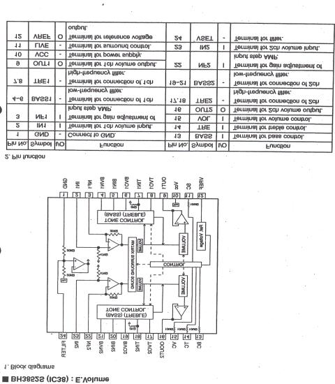
12 DESCRIPTION OF MAJOR IC TA2104BN (IC101) AM/FM 1 CHIP TUNER Block Diagram 1-12

13 AN7345K (IC201) DUAL RECORD/PLAYBACK PRE-AMPLIFIER Block Diagram 1-13
14 1-14
15 1-15
16 BLOCK DIAGRAM 1-16
SERVICE MANUAL COMPACT COMPONENT SYSTEM
 SERVICE MANUAL COMPACT COMPONENT SYSTEM MB531 2006 6 DX-T99A,DX-T99EE,DX-T99US,DX-T99UW, DX-T99UX,DX-T99UG,DX-T99UN, DX-T77EE,DX-T77US,DX-T77UW,DX-T77UX, DX-T77UY,DX-T77UG,DX-T77UN, DX-T66EE,DX-T66US,DX-T66UW,DX-T66UX,
BELSON. BSA-1061 (2 W remote) MICRO COMPONENT SYSTEM
 MICRO COMPONENT SYSTEM") BELSON (2 W remote) MICRO COMPONENT SYSTEM MODEL CAUTION: Before servicing the chassis, read the " important service safety information" section on page 2 of this manual. MICRO HI-FI STEREO RADIO WITH
BELSON (2 W remote) MICRO COMPONENT SYSTEM MODEL CAUTION: Before servicing the chassis, read the " important service safety information" section on page 2 of this manual. MICRO HI-FI STEREO RADIO WITH
SRM-323. DRIVER UNIT for EARSPEAKERS. Operating Manual CAUTION
 SM-2 Ⅱ DIVE UNIT for EASPEAKES Operating Manual Thank you very much purchasing STAX s SM-2Ⅱ model. To enable you to use the unit in complete safety for many years, please read these instructions carefully.
Operating Instruction Manual ELECTRONIC MUSIC AMPLIFICATION SYSTEM. Model KD-1. Toa Electric Co., Ltd. KOBE, JAPAN
 Operating Instruction Manual ELECTRONIC MUSIC AMPLIFICATION SYSTEM Model KD-1 Toa Electric Co., Ltd. KOBE, JAPAN Contents Precautions... 1 General Description... 2 Features... 2 Front Panel: Names of components
ZM-6. Professional 19 Rack Mixer USER MANUAL. Content
 Professional 19 Rack Mixer ZM-6 USER MANUAL Thank you for buying an LD Systems audio product. Please read these operating instructions carefully before you use the product for the first time and keep them
MAX Series Bass Amplifiers
 MAX Series Bass Amplifiers Operating Manual www.peavey.com FCC Compliancy Statement This device complies with Part 15 of the FCC rules. Operation is subject to the following two conditions: (1) this device
MIXING CONSOLE CX-124 CX-164. TOA Corporation. Operating Instructions
 MIXING CONSOLE Operating Instructions CX-124 CX-164 Please follow the instructions in this manual to obtain the optimum results from these units. We also recommend you to keep this manual handy for future
SERVICE MANUAL CD RECEIVER MA KD-G120,KD-G120R,KD-G123, KD-G124,KD-G125,KD-G126, KD-G161,KD-G162 KD-G120R KD-G162
 KD-G126 KD-G161 KD-G125 KD-G162 SERVICE MANUAL CD RECEIVER MA233 2005 12 KD-G120,KD-G120R,KD-G123, KD-G124,KD-G125,KD-G126, KD-G161,KD-G162 KD-G120 KD-G120R KD-G120,KD-G120R Area suffix J -------------
SDI SPECTRADYNAMICS, INC. HIGH PERFORMANCE DISTRIBUTION AMPLIFIER OPERATING MANUAL
 SPECTRADYNAMICS, INC. HIGH PERFORMANCE DISTRIBUTION AMPLIFIER HPDA15RMC OPERATING MANUAL SPECTRADYNAMICS, INC 1849 Cherry St. Unit 2. Louisville, CO 80027 Phone: (303) 6651852 Fax: (303) 6046088 www.spectradynamics.com
T L Audio CRIMSON SERIES. User Manual EQ-3012 PARAMETRIC EQUALISER. Tony Larking Professional Sales Limited, Letchworth, England.
 T L Audio CRIMSON SERIES User Manual EQ-3012 PARAMETRIC EQUALISER Tony Larking Professional Sales Limited, Letchworth, England. Tel: 01462 490600. International +44 1462 490600. Fax: 01462 490700. International
T L Audio. User Manual EQ1 VALVE EQUALISER. Tony Larking Professional Sales Limited, Letchworth, England.
 T L Audio User Manual EQ1 VALVE EQUALISER Tony Larking Professional Sales Limited, Letchworth, England. Tel: 01462 490600, International +44 1462 490600. Fax: 01462 490700, International +44 1462 490700.
T L Audio CRIMSON SERIES. User Manual EQ-3011 EQUALISER. Tony Larking Professional Sales Limited, Letchworth, England.
 T L Audio CRIMSON SERIES User Manual EQ-3011 EQUALISER Tony Larking Professional Sales Limited, Letchworth, England. Tel: 01462 490600. International +44 1462 490600. Fax: 01462 490700. International +44
HCD-DX50/RG80 SERVICE MANUAL MINI HI-FI COMPONENT SYSTEM. Canadian Model. Australian Model E Model. Ver
 SERVICE MANUAL Ver 1.3 2003. 10 Canadian Model HCD-RG80 Australian Model E Model HCD-DX50 HCD-DX50/RG80 are the tuner, deck, CD and amplifier section in MHC-DX50/RG80. Photo : HCD-DX50 Model Name Using
SRF-T615 SERVICE MANUAL FM STEREO/AM PLL SYNTHESIZED RADIO. Tourist Model. Ver SPECIFICATIONS MICROFILM
 SRF-T615 SERVICE MANUAL Ver 1.0 1999.10 Tourist Model SPECIFICATIONS FM STEREO/AM PLL SYNTHESIZED RADIO MICROFILM TABLE OF CONTENTS Specifications... 1 1. GENERAL Location and Function of Controls... 2
Isolated Variable AC Line Supply Instruction Manual
 1506 Isolated Variable AC Line Supply Instruction Manual 10/2011 TABLE OF CONTENTS SECTION DESCRIPTION PAGE NO. 1 INTRODUCTION 1 2 SPECIFICATIONS 2 3 DESCRIPTION 3 4 OPERATING INSTRUCTIONS 5 5 SERVICE
FOUNTEK ALTITUDE Integrated Amplifier OWNERS MANUAL. A3500 ( Version -V1) 240V AC
 240V AC") FOUNTEK ALTITUDE 3500 Integrated Amplifier OWNERS MANUAL A3500 ( Version -V1) 240V AC 24-10-05 CONTENTS 3. INTRODUCTION 4. IMPORTANT NOTES ( WARNING!) 5. POWER INPUT CONNECTION 6. CONNECTING SPEAKERS 7.
FOUNTEK ALTITUDE 3500 Integrated Amplifier OWNERS MANUAL A3500 ( Version -V1) 240V AC 24-10-05 CONTENTS 3. INTRODUCTION 4. IMPORTANT NOTES ( WARNING!) 5. POWER INPUT CONNECTION 6. CONNECTING SPEAKERS 7.
POWER SUPPLY MODEL XP-720. Instruction Manual ELENCO
 POWER SUPPLY MODEL XP-720 Instruction Manual ELENCO Copyright 2016, 1997 by ELENCO Electronics, Inc. All rights reserved. Revised 2016 REV-H 753270 No part of this book shall be reproduced by any means;
IMPORTANT SAFETY INSTRUCTIONS
 WR-11 Version 1 IMPORTANT SAFETY INSTRUCTIONS 1. Read these instructions. 2. Keep these instructions. 3. Heed all warnings. 4. Follow all instructions. 5. Do not use this apparatus near water. 6. Clean
TX-28LK1P TX-25LK1P. Colour Television. Z8 Chassis SPECIFICATION. Power Consumption: 97W {105W} RCA IN Video 1V p-p 75Ω RCA IN Audio 500mV rms 10kΩ
 ORDER No. 00-SM-016 Colour Television TX-28LK1P TX-25LK1P Z8 Chassis SPECIFICATION (Information in brackets { } refers to model TX-25LK1P) Power Source: 220-240V a.c., 50Hz Power Consumption: 97W {105W}
SDI SPECTRADYNAMICS, INC. LOW NOISE FREQUENCY REFERENCE OPERATING MANUAL
 SPECTRADYNAMICS, INC. LOW NOISE FREQUENCY REFERENCE LNFR-100E OPERATING MANUAL SPECTRADYNAMICS, INC 1849 Cherry St. Unit 2. Louisville, CO 80027 Phone: (303) 665-1852 Fax: (303) 604-6088 www.spectradynamics.com
SLP-2002 Stereo Balanced Vacuum Tube Preamplifier
 SLP-2002 Stereo Balanced Vacuum Tube Preamplifier Fully Balanced Vacuum Tube Line Stage Circuit Design with Cinema Bypass and Remote Volume Control CARY AUDIO DESIGN 1020 GOODWORTH DRIVE APEX, NORTH CAROLINA
Big Knob Radio User s Guide Item Number: All brand names and trademarks are the property of their respective owners
 Big Knob Radio User s Guide Item Number: 11009726 All brand names and trademarks are the property of their respective owners Contents Overview...3 Quick Start Guide...3 Package Contents...3 Diagram of
UNITED MOTORS SERVICE AUTO RADIO BULLETIN
 UNITED MOTORS SERVICE DIVISION OF GENERAL MOTORS CORPORATION General Offices - Detroit AUTO RADIO BULLETIN Bulletin 6D-854 Date 11-1-54 Page 1 FIRST ISSUE GENERAL SUBJECT: SERVICE INSTRUCTIONS - 12V CHEVROLET
CX-A6 Amplifier Installation & User Guide V9.0
 CX-A6 Amplifier Installation & User Guide V9.0 Cloud Electronics Limited 140 Staniforth Road, Sheffield, S9 3HF England Tel + 44 (0) 114 244 7051 Fax + 44 (0) 114 242 5462 E-mail info@cloud.co.uk Web site
HAMTRONICS TB901 FM EXCITER INSTALLATION, OPERATION, & MAINTENANCE
 HAMTRONICS TB901 FM EXCITER INSTALLATION, OPERATION, & MAINTENANCE GENERAL INFORMATION. The TB901 is a single-channel low power fm transmitter (exciter) designed to provide 300-600 milliwatts continuous
CMA-100. User Manual. Counter Measures Amplifier
 CMA-100 Counter Measures Amplifier User Manual Research Electronics International, LLC 455 Security Drive, Cookeville, TN 38506 U.S.A. (800) 824-3190 (US Only) +1 931-537-6032 www.reiusa.net Copyright
19'' Rack Mount 300 Watt Power Amplifier/ Mixer w/70v Output & Mic Talkover USER MANUAL
 19'' Rack Mount 300 Watt Power Amplifier/ Mixer w/70v Output & Mic Talkover USER MANUAL Your new PYRAMID PA305 300 Watt P.A. Amplifier gives you the power and versatility you need in a professional sound
TABLE OF CONTENTS. 1) Introduction 2. 2) Unpacking your preamplifier 2. 3) Installing the preamp into your system 3
 Introduction 2. 2) Unpacking your preamplifier 2. 3) Installing the preamp into your system 3") TABLE OF CONTENTS 1) Introduction 2 2) Unpacking your preamplifier 2 3) Installing the preamp into your system 3 4) Operation of your preamplifier 6 5) Troubleshooting 8 6) Registration of your preamplifier
TABLE OF CONTENTS 1) Introduction 2 2) Unpacking your preamplifier 2 3) Installing the preamp into your system 3 4) Operation of your preamplifier 6 5) Troubleshooting 8 6) Registration of your preamplifier
Model 7000 Low Noise Differential Preamplifier
 Model 7000 Low Noise Differential Preamplifier Operating Manual Service and Warranty Krohn-Hite Instruments are designed and manufactured in accordance with sound engineering practices and should give
IMPORTANT SAFETY INSTRUCTIONS
 WR-1 Version 1 IMPORTANT SAFETY INSTRUCTIONS 1. 2. 3. 4. 5. 6. 7. 8. 9. Read these instructions. Keep these instructions. Heed all warnings. Follow all instructions. Do not use this apparatus near water.
CMA-100. Counter Measures Amplifier. Owner s Guide
 CMA-100 Counter Measures Amplifier Owner s Guide INTRODUCTION: Thank you for purchasing the CMA-100 Countermeasures Amplifier. When doing a Counter-surveillance investigation, it is important to analyze
KLD Guitar AMP MOJO12HR
 KLD Guitar AMP MOJO12HR TMB-18H Tube Guitar Amplifier Manual Kailing Electronic Co.,Ltd http://www.kldguitar.com Intended to alert the user to the presence of un-insulated dangerous voltage within the
2520 Pulsed Laser Diode Test System
 Complete pulse test of laser diode bars and chips with dual photocurrent measurement channels 0 Pulsed Laser Diode Test System Simplifies laser diode L-I-V testing prior to packaging or active temperature
FCC ID: AXI IC: 10239A Alignment
 Introduction The VX-261 is carefully aligned at the factory for the specified performance across the frequency range specified for each version. Realignment should therefore not be necessary except in
HOOKING IT UP. Unpacking and Inspection. Installing in a Rack CHAPTER 3: Hooking It Up
 CHAPTER 3: HOOKING IT UP Unpacking and Inspection Your Studio 32 was packed carefully at the factory, and the container was designed to protect the unit during shipping. Please retain this container in
CFS-717S SERVICE MANUAL RADIO CASSETTE-CORDER. E Model. Ver SPECIFICATIONS
 CFS-717S SERVICE MANUAL Ver 1.1 1999. 11 E Model Model Name Using Similar Mechanism Tape Transport Mechanism Type CFS-W475 MF-W475 SPECIFICATIONS RADIO CASSETTE-CORDER MICROFILM Ver 1.1 1999. 11 MODEL
DEC-001 Installation Instructions
 DEC-001 Installation Instructions Skill Level: The installation of this assembly requires a medium level of expertise in working with modern electronic equipment. The use of appropriate tools, correct
USER MANUAL VIVALDI MZ550A. Distribution Mixer Amplifier
 USER MANUAL VIVALDI MZ550A Distribution Mixer Amplifier 1. Security Precautions Carefully READ the instruction in this manual before use. Be sure to OBSERVE the INSTRUCTION in this manual regard convention
XR12. Frequency Change Procedure IS Issue August 2007
 XR12 Frequency Change Procedure IS07013 Issue 1.0... 31 August 2007 Nautel Limited 10089 Peggy's Cove Road, Hackett's Cove, NS, Canada B3Z 3J4 T.877 6 nautel (628835) or +1.902.823.2233 F.+1.902.823.3183
SRF-M75PM SERVICE MANUAL FM STEREO/AM PLL SYNTHESIZED RADIO. US Model Canadian Model AEP Model E Model Australian Model. Ver
 SRF-M75PM SERVICE MANUAL Ver 1.0 1999. 04 US Model Canadian Model AEP Model E Model Australian Model SPECIFICATIONS US, Canadian, and E models AEP, Australian models FM STEREO/AM PLL SYNTHESIZED RADIO
411LA Broadband Power Amplifier
 411LA Broadband Power Amplifier HIGH RF VOLTAGES MAY BE PRESENT AT THE OUTPUT OF THIS UNIT. All operating personnel should use extreme caution in handling these voltages and be thoroughly familiar with
************* OWNER'S MANUAL STAX1250/2 STAX1800/2 STAX2200/2 STAX1200/4 STAX1600/4 STAX2300/4 STAX2000/1D STAX4000/1D STAX5500/1D
 ************* OWNER'S MANUAL STAX1250/2 STAX1800/2 STAX2200/2 STAX1200/4 STAX1600/4 STAX2300/4 STAX2000/1D STAX4000/1D STAX5500/1D INTRODUCTION Power Acoustik amplifiers provide high-performance sound
UNITED MOTORS SERVICE D IV ISIO N OF GENERAL M O TO RS C O R P O R A T IO N. General Offices - Detroit AUTO RADIO BULLETIN
 UNITED MOTORS SERVICE D IV ISIO N OF GENERAL M O TO RS C O R P O R A T IO N General Offices - Detroit AUTO RADIO BULLETIN Bulletin 6D-855 Date 11-1-54 Page 1 FIRST ISSUE SUBJECT: SERVICE INSTRUCTIONS -
TM-152 AM STEREO TUNER
 Cat. No. 31-1967 TM-152 AM STEREO TUNER PLEASE READ BEFORE USING THIS EQUIPMENT CONTROLS AND FUNCTIONS The TM-152, a mini-sized Tuner, adds an exciting new dimension to your hi fi system... AM Stereo.
SP980. Cordless Stereo 863MHZ. Speaker System. User s Manual INTRODUCTION FEATURES. Please read before using the equipment
 SP980 Cordless Stereo 863MHZ Speaker System INTRODUCTION This 863 MHz stereo wireless speaker system uses latest wireless technology that enables you to enjoy music and TV sound anywhere inside or outside
Owner s Manual. Model: SP-120MKII KT88 Ultra-linear Integrated Stereo Tube Amplifier
 Model: SP-120MKII Ultra-linear Integrated Stereo Tube Amplifier Owner s Manual Raysonic Inc. P.O.BOX 46565, Toronto, Ontario M1T 3V8 Canada sales@raysonicaudio.com Raysonic Inc. P.O.BOX 46565, Toronto,
V160R ELECTRIC GUITAR AMPLIFIER WITH A TUBE PREAMP, REVERB AND BUILT-IN CHROMATIC TUNER. User s Manual
 TM V160R ELECTRIC GUITAR AMPLIFIER WITH A TUBE PREAMP, REVERB AND BUILT-IN CHROMATIC TUNER User s Manual TM Vendetta is a trademark of GHS Corporation Battle Creek MI, USA May be covered by one or more
SERVICE MANUAL 2 CHANNEL POWER AMPLIFIER GFA-5400
 SERVICE MANUAL 2 CHANNEL POWER AMPLIFIER GFA-5400 TABLE OF CONTENTS Introduction...1 Version 1 vs. Version 2........ 1 Test Procedures............. 1 Parts List...2 Specifications...6 Chassis Layout...............
MA V 35W Mixer Amplifier
 MA V W Mixer Amplifier User Manual MA Mixer Amplifier EQUALISER MASTER VOLUME POWER ON - + - + - + OFF MIC MIC LINE /LINE Hz khz khz POWER CONSUMPTION: W (max.) Order code: CRAM Safety advice WARNING FOR
User Manual VOLUME PTT 1 MIC/LINE 2 MIC/LINE 3 MIC/LINE 4 MIC/LINE 5 MIC/LINE 6 MIC/LINE 7 MIC/LINE 8 MIC/LINE 9 MIC/LINE 10 LEVEL LEVEL TREBLE 6 MIC
 + 7 54 ZM 0 Audio Mixer User Manual www.cleveracoustics.co.uk CAUTION RISK OF ELECTRIC SHOCK DO NOT OPEN. NO USER SERVICABLE PARTS INSIDE WARNING: TO REDUCE THE RISK OF FIRE OR ELECTRIC SHOCK. DO NOT EXPOSE
Treetop Circuits Owner s Manual for SB-SB-600 Adapter Version 1
 The SB-600 SSB adapter from Treetop Circuits (Fig. 1) is designed specifically as an accessory to the Hammarlund SP-600 series of receivers. It provides enhanced performance on SSB and CW signals, using
UA ª 35T II Utility Amplifier OPERATING INSTRUCTIONS
 OPERATING INSTRUCTIONS Intended to alert the user to the presence of uninsulated "dangerous voltage" within the product's enclosure that may be of sufficient magnitude to constitute a risk of electric
14. Unplug unit during lightning storms or when unused for long periods of time.
 IMPORTANT SAFETY INSTRUCTIONS. READ AND SAVE THESE INSTRUCTIONS. HEED ALL WARNINGS. This symbol, wherever it appears, alerts the user to the presence of uninsulated dangerous voltage within the product
PULSE DISTRIBUTION AMPLIFIER OPERATING MANUAL
 SPECTRADYNAMICS, INC PD5-RM-B PULSE DISTRIBUTION AMPLIFIER OPERATING MANUAL SPECTRADYNAMICS, INC 1849 Cherry St. Unit 2. Louisville, CO 80027 Phone: (303) 665-1852 Fax: (303) 604-6088 www.spectradynamics.com
INSTRUCTION MANUAL POWERED MIXER MX-628
 INSTRUCTION MANUAL POWERED MIXER MX-628 Please follow the instructions in this manual to obtain the optimum results from this unit. We also recommend that you keep this manual handy for future reference.
Copyright 1999 Wheatfield Audio LLC. All rights reserved. Printed in USA 11/99
 HA-2 Headphone Amplifier User s Manual Contents Safety... 3 Unpacking, Setup, and Connection... 4 Unpacking the amplifier... 4 Installing the tubes... 4 Connecting the amplifier... 4 Listening with the
Yaesu FT-8800R Alignment
 DUAL BAND FM TRANSCEIVER Introduction and Precautions The FT-8800R has been carefully aligned at the factory for the specified performance across the 144 MHz and 430 MHz amateur bands. Realignment should
The Aleph 2 is a monoblock 100 watt audio power amplifier which operates in single-ended class A mode.
 Pass Laboratories Aleph 2 Service Manual Rev 0 2/1/96 Aleph 2 Service Manual. The Aleph 2 is a monoblock 100 watt audio power amplifier which operates in single-ended class A mode. The Aleph 2 has only
V50D ELECTRIC GUITAR AMPLIFIER WITH DIGITAL DELAY AND CHORUS. User s Manual
 V50D ELECTRIC GUITAR AMPLIFIER WITH DIGITAL DELAY AND CHORUS User s Manual R Velocity is a registered trademark of GHS Corporation Battle Creek MI, USA May be covered by one or more of the following: U.S.
The Aleph 5 is a stereo 60 watt audio power amplifier which operates in single-ended class A mode.
 Pass Laboratories Aleph 5 Service Manual Rev 0 9/20/96 Aleph 5 Service Manual. The Aleph 5 is a stereo 60 watt audio power amplifier which operates in single-ended class A mode. The Aleph 5 has only two
3 T856/857 Initial Tuning & Adjustment
 M850-00 T856/857 Initial Tuning & Adjustment C3.1 3 T856/857 Initial Tuning & Adjustment The following section describes the full tuning and adjustment procedure and provides information on: channel programming
Figure 2 shows the actual schematic for the power supply and one channel.
 Pass Laboratories Aleph 3 Service Manual rev 0 2/1/96 Aleph 3 Service Manual. The Aleph 3 is a stereo 30 watt per channel audio power amplifier which operates in single-ended class A mode. The Aleph 3
SRF-PSY03 SERVICE MANUAL FM STEREO/AM RADIO. US Model SPECIFICATIONS. Photo: Violet model MICROFILM
 SRF-PSY03 SERVICE MANUAL US Model Photo: Violet model SPECIFICATIONS STEREO/ RADIO MICROFILM TABLE OF CONTENTS 1. GENERAL... 3. DISASSEMBLY... 4 Notes on chip component replacement Never reuse a disconnected
Maintenance/ Discontinued
 ICs for Audio Common Use AN7348K Dual Record/Playback Pre-Amplifier IC for Double Cassette Overview The AN7348K is a monolithic integrated circuit designed for double cassette recorder. It has dual channel
PA240 ORDERCODE D6113
 PA240 ORDERCODE D6113 Congratulations! You have bought a great, innovative product from DAP Audio. The Dap Audio PA240 brings excitement to any venue. Whether you want simple plug-&-play action or a sophisticated
English KS-DR3005D POWER AMPLIFIER: INSTRUCTION MANUAL
 KS-DR005D POWER AMPLIFIER: INSTRUCTION MANUAL B5E-009-00/00 [W] WARNING If the fuse blows, first make sure the wires aren t touching to cause a short circuit then replace the old fuse with one with the
ICF-C112 SERVICE MANUAL FM/AM CLOCK RADIO. E Model. Ver Sony Corporation SPECIFICATIONS
 SERVICE MANUAL E Model Ver 1.0 2003. 03 SPECIFICATIONS Time display: 12-hour system Frequency range: : 87.5-108 MHz AM: 530-1710 khz Speaker: Approx. 6.6 cm (2 5/8 inches) dia., 8 ohm Power output: 120
Instruction Kit MIXER AMPLIFIER GT 60C GT 125C. GROMMES-PRECISION SINCE-46
 Instruction Kit GT 60C GT 125C MIXER AMPLIFIER GROMMES-PRECISION 1-800-SINCE-46 www.grommesprecision.com Thank you for purchasing from Grommes~Precision! Grommes~Precision and its commercial audio division,
Continuous Power Output Stereo Mode 130 watts/ch into 8 ohms (20-20 khz, <0.03% THD)
") Quality Uncompromised Technical Manual STEREO POWER AMPLIFIER RB-070 Table of Contents Specification... Parts List... Adjustment... Case Outlines... PCB Assembly...~4 Schematic Diagram...5~6 Specification
Quality Uncompromised Technical Manual STEREO POWER AMPLIFIER RB-070 Table of Contents Specification... Parts List... Adjustment... Case Outlines... PCB Assembly...~4 Schematic Diagram...5~6 Specification
LBI-30398N. MAINTENANCE MANUAL MHz PHASE LOCK LOOP EXCITER 19D423249G1 & G2 DESCRIPTION TABLE OF CONTENTS. Page. DESCRIPTION...
 MAINTENANCE MANUAL 138-174 MHz PHASE LOCK LOOP EXCITER 19D423249G1 & G2 LBI-30398N TABLE OF CONTENTS DESCRIPTION...Front Cover CIRCUIT ANALYSIS... 1 MODIFICATION INSTRUCTIONS... 4 PARTS LIST AND PRODUCTION
Trace Elliot Elf Bass Instrument Amplifier
 Trace Elliot Elf Bass Instrument Amplifier Owner s Manual FCC Compliancy Statement This device complies with Part 15 of the FCC rules. Operation is subject to the following two conditions: (1) this device
CLASS D MONO AMPLIFIER GM-D8601 GM-D9601. Owner s Manual
 CLASS D MONO AMPLIFIER GM-D8601 GM-D9601 Owner s Manual Before you start BE SURE TO OBSERVE THE FOLLOWING GUIDELINES:! Do not turn up the volume so high that you can t hear what s around you.! Use caution
PLANNING YOUR SYSTEM
 INTRODUCTION HERTIAGE amplifiers provide high-performance sound reinforcement for your mobile audio equipment. Its versatility enables compatibility with optional Equalizers, Frequency Dividing Crossover
WOO AUDIO WA2. Stereo Headphone & Pre Amplifier. Single-Ended, Class-A, Output Transformer-Less (OTL) Owner s Manual
 Owner s Manual") WOO AUDIO WA2 Stereo Headphone & Pre Amplifier Single-Ended, Class-A, Output Transformer-Less (OTL) Owner s Manual Please review this manual before operating your WOO AUDIO product. Inc. All rights reserved.
WOO AUDIO WA2 Stereo Headphone & Pre Amplifier Single-Ended, Class-A, Output Transformer-Less (OTL) Owner s Manual Please review this manual before operating your WOO AUDIO product. Inc. All rights reserved.
MASTR II AUXILIARY RECEIVER 19D417546G7 & G8 & ANTENNA MATCHING UNITS 19C321150G1-G2. Maintenance Manual LBI-30766L. Mobile Communications
 L Mobile Communications MASTR II AUXILIARY RECEIVER 19D417546G7 & G8 & ANTENNA MATCHING UNITS 19C321150G1-G2 Printed in U.S.A Maintenance Manual TABLE OF CONTENTS Page SPECIFICATIONS.....................................................
SERVICE MANUAL CD RECEIVER
 MA 00 0 SERCE MANUAL SERCE MANUAL CD RECEIVER KD-GE, KD-GEX, KD-GEY, KD-GEU, KD-GEE, KD-G0J, KD-GE, KD-GEX, KD-GEY, KD-GEU, KD-GEE, KD-GUI, KD-GU, KD-GUN, KD-GUT, KD-GUH, KD-GU, KD-GUN, KD-GUT,
PB 700 PB 1000 PB 1100 PB 1500 PB 2600 PB 1200 PB 1700 PB 2200 PB 2700 USER'S MANUAL.
 PB 700 PB 1000 PB 1100 PB 1500 PB 2600 PB 1200 PB 1700 PB 2200 PB 2700 USER'S MANUAL www.pyramidcaraudio.com congratulations... on your purchase of a Pyramid America Series amplifier. This amplifier extends
INSTRUCTION MANUAL LKG 601 Electrical Safety Analyzer
 INSTRUCTION MANUAL LKG 601 Electrical Safety Analyzer 110 Toledo Street Farmingdale, NY 11735 USA http://www.netech.org 510-USER-Manual Rev3 10/29/2007 Dear User, We appreciate your purchase of the LKG
MPC-XU Universal Crossover
 MPC-U Universal Crossover For JBL MPC and MPA amplifiers Owner s Manual and Installation Guide I. Description The MPC-U is a dual-channel universal crossover filter accessory for use with JBL MPC and MPA
CALRAD 25 series - potentiometers
 25 series - potentiometers audio /linear SUB-MINIATURE VOLUME CONTROLS Linear taper, extremely smooth for quiet operation. 1 2" dia. fits into 1 4" hole. Shaft 3 16" dia. Thread length 7 32", shaft length
Operation Manual. Model SG Elenco Precision Wide Band Signal Generator
 99 Washington Street Melrose, MA 02176 Phone 781-665-1400 Toll Free 1-800-517-8431 Visit us at www.testequipmentdepot.com Elenco Precision Wide Band Signal Generator Model SG-9000 Operation Manual CONTENTS
ERICSSONZ LBI-30398P. MAINTENANCE MANUAL MHz PHASE LOCKED LOOP EXCITER 19D423249G1 & G2 DESCRIPTION TABLE OF CONTENTS
 MAINTENANCE MANUAL 138-174 MHz PHASE LOCKED LOOP EXCITER 19D423249G1 & G2 TABLE OF CONTENTS Page DESCRIPTION... Front Cover CIRCUIT ANALYSIS...1 MODIFICATION INSTRUCTIONS...4 PARTS LIST...5 PRODUCTION
 file:///c /BoatAnchors/Hammarlund/HQ170A/HQ170SVC.TXT Dear OM: This form is being prepared to provide prompt attention to a complaint as a result of trouble that may be experienced in the field. In addition
MIXER POWER AMPLIFIER BG-130
 OPERATING INSTRUCTIONS MIXER POWER AMPLIFIER BG-115 BG-130 TO REDUCE THE RISK OF ELECTRICAL SHOCK, DO NOT REMOVE COVER. NO USER SERVICEABLE PARTS INSIDE. REFER SERVICING TO QUALIFIED SERVICE PERSONNEL
CON NEX HP. OWNER'S MANUAL Full Channel AM/FM Amateur Mobile Transceiver TABLE OF CONTENTS TUNING THE ANTENNA FOR OPTIMUM S.W.R..
 TABLE OF CONTENTS PAGE SPECIFICATIONS... 2 INSTALLATION... 3 LOCATION... 3 CON NEX - 4300HP MOUNTING THE RADIO... 3 IGNITION NOISE INTERFERENCE... 4 ANTENNA... 4 TUNING THE ANTENNA FOR OPTIMUM S.W.R..
PA WATT PORTABLE PA SYSTEM PRODUCT MANUAL
 PA-5150 5 150-WATT PORTABLE PA SYSTEM PRODUCT MANUAL THANK YOU FOR CHOOSING POLSEN. The Polsen PA-5150 is an active PA system that s ideal for solo performers or vocalists. It can be used as a PA system
Preliminary Information (There will be updates)
") This Manual is provided by CBTricks.com Someone who wanted to help you repair your equipment put together this information. Cobra150GTL DX If you would like to help us put more manuals online support us.
This Manual is provided by CBTricks.com Someone who wanted to help you repair your equipment put together this information. Cobra150GTL DX If you would like to help us put more manuals online support us.
TOA 500 SERIES MIXER POWER AMPLIFIER
 TOA 500 SERIES MIXER POWER AMPLIFIER Operation Instruction Manual A-503A A-506A A-512A Features General Description 1. High quality design and construction. 2. Full frequency response: 50-15,000Hz, ±3dB.
TS-930: Installing the Inrad Roofing Filter Mod
 TS-930: Installing the Inrad Roofing Filter Mod The TS-930 roofing filter mod consists of a 6 pole, 4 to 5 khz wide filter followed by a high dynamic range, feedback amplifier. The amplifier provides enough
PAM-240/360 Public Address Amplifier
 PAM-240/360 Public Address Amplifier PAM-240 PUBLIC ADDRESS AMPLIFIER CLIP 0-6 -8-11 -14-19 PROT CHANNEL 1 CHANNEL 2 CHANNEL 3 CHANNEL 4 CHANNEL 5 CHANNEL 6 BASS TREBLE MASTER CHIME SP 1 SP 2 SP 3 SP 4
POWERED MIXER DIGITAL ECHO EFFECT ECHO LEVEL ECHO LEVEL ECHO LEVEL ECHO LEVEL ECHO VOL REPEAT MPM CHANNEL POWERED MIXER OWNER S MANUAL
 POWERED MIXER DIGITAL ECHO EFFECT ECHO LEVEL ECHO LEVEL ECHO LEVEL ECHO LEVEL ECHO VOL REPEAT MPM 480 4-CHANNEL POWERED MIXER OWNER S MANUAL MPM 480 4-CHANNEL POWERED MIXER Congratulations! You have just
PC to Radio Audio and Key-line Interface
 PC to Radio Audio and Key-line Interface Background - This simple interface was developed to capacitive couple audio signals between a radio and PC, to provide a means of adjusting audio levels between
DEPARTMENT OF THE ARMY TECHNICAL BULLETIN CALIBRATION PROCEDURE FOR SHF SIGNAL GENERATOR AN/USM-47 (HEWLETT-PACKARD MODEL 626A) (NSN )
 (NSN )") DEPARTMENT OF THE ARMY TECHNICAL BULLETIN CALIBRATION PROCEDURE FOR SHF SIGNAL GENERATOR AN/USM-47 (HEWLETT-PACKARD MODEL 626A) (NSN 6625-00-455-6917) Headquarters, Department of the Army, Washington,
DEPARTMENT OF THE ARMY TECHNICAL BULLETIN CALIBRATION PROCEDURE FOR SHF SIGNAL GENERATOR AN/USM-47 (HEWLETT-PACKARD MODEL 626A) (NSN 6625-00-455-6917) Headquarters, Department of the Army, Washington,
MFJ-249B HF/VHF SWR ANALYZER
 TABLE OF CONTENTS MFJ-249B... 2 Introduction... 2 Powering The MFJ-249B... 3 Battery Installation... 3 Alkaline Batteries... 3 NiCd Batteries... 4 Power Saving Mode... 4 Operation Of The MFJ-249B...5 SWR
CABINET POWERED MIXING CONSOLE
 R SHS AUDIO SPMU- 00 CABINET POWERED MIXING CONSOLE USER'S MANUAL SAFETY INSTRUCTIONS SPECIFICATIONS Inputs Input modes Input Impedance Rated Input level Connector WARNING - TO REDUCE THE RISK OF FIRE
OPERATING THE SYLVANIA STEREO RECEIVER RS4743
 OPERATING THE SYLVANIA STEREO RECEIVER RS3 TABLE OF CONTENTS Page Introduction 2 Accessory Components 3 Initial Hook-Up Connecting Accessory Components Antenna Connections Jacks Aux Jacks Tape Jacks Pre-Amp
Model 4402B. Ultra-Pure Sinewave Oscillator 1Hz to 110kHz Typical Distortion of % Serial No. Operating Manual
 Model 4402B Ultra-Pure Sinewave Oscillator 1Hz to 110kHz Typical Distortion of 0.0005% Serial No. Operating Manual 15 Jonathan Drive, Unit 4, Brockton, MA 02301 U.S.A. Tel: (508) 580-1660; Fax: (508) 583-8989
D ELCO. electronic parts AUTO RADIO BULLETIN. Connect Signal Generator to
 D ELCO electronic parts AUTO RADIO BULLETIN Bulletin 6D-864 Date 10-15-56 Page 1 FIRST ISSUE SUBJECT: SERVICE INSTRUCTIONS - CHEVROLET CUSTOM DELUXE WITH PUSH BUTTON TUNING - MODEL 987575 GENERAL M O U
Studio. PRO High Performance Professional Audio MODEL:PA105/PA205 PA AMPLIFIER
 Studio PRO High Performance Professional Audio MODEL:PA105/PA205 PA AMPLIFIER INTRODUCTION Your New PYRAMID PA105/PA205 PA AMPLIFIER gives you the power and versatility you need in a professional sound
IC-781: Installing the Inrad Roofing Filter Mod
 IC-781: Installing the Inrad Roofing Filter Mod The Icom IC-781 roofing filter mod consists of a 6-pole, 4 to 5 khz wide filter followed by a high dynamic range, feedback amplifier. The amplifier provides