SRF-M75PM SERVICE MANUAL FM STEREO/AM PLL SYNTHESIZED RADIO. US Model Canadian Model AEP Model E Model Australian Model. Ver
|
|
|
- Dominick Malone
- 5 years ago
- Views:
Transcription
1 SRF-M75PM SERVICE MANUAL Ver US Model Canadian Model AEP Model E Model Australian Model SPECIFICATIONS US, Canadian, and E models AEP, Australian models FM STEREO/AM PLL SYNTHESIZED RADIO MICROFILM
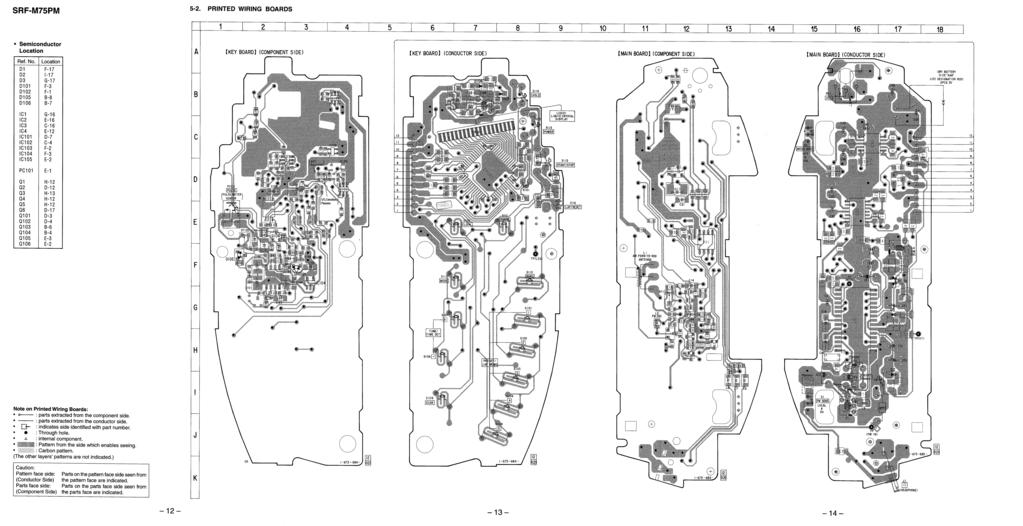
2 SECTION 1 SERVICING NOTES TABLE OF CONTENTS 1. SERVICING NOTES GENERAL DISASSEMBLY ELECTRICAL ADJUSTMENTS TUNER Section... 6 PULSE MONITOR Section DIAGRAMS 5-1. Block Diagram Printed Wiring Boards Schematic Diagram IC Pin Function Description Forced Reset The system microprocessor can be reset in the following procedure. Use these procedure when the unit cannot be worked normally due to the overrunning of the microprocessor, etc. Procedure: 1. Set to radio OFF. 2. While pressing the [SCAN] button, press two buttons of [START/STOP] and [BAND] simultaneously for 5 seconds. 3. The unit is reset, and display blinking AM 12:00. Notes on chip component replacement Never reuse a disconnected chip component. Notice that the minus side of a tantalum capacitor may be damaged by heat. 6. EXPLODED VIEW ELECTRICAL PARTS LIST
3 SECTION 2 GENERAL This section is extracted from instruction manual. US, Canadian, and E models AEP, Australian models 3
4 SECTION 3 DISASSEMBLY This set can be disassembled in the order shown below. Set Cabinet (Front) Assy Cabinet (Rear) Assy Key Board Main Board Knob (A) Note: Follow the disassembly procedure in the numerical order given. CABINET (FRONT)/(REAR) ASSY 2 three screws (B1.7 8) 1 Remove the battery case lid of the arrow. 2 two screws (B1.7 8) 4 cabinet (rear) assy 3 cabinet (front) assy KEY BOARD 1 three claws 2 Open the key board to direction of the arrow. 1 four claws 4
5 MAIN BOARD Note: Check that two switch (S1, S2) is latched with two adaptors when carrying out installation. 3 knob (vol) 5 main board 4 two claws S2 S1 2 screw (B1.7 8) 1 Remove two solders. KNOB (A) 2 two knobs (A) 1 claw 1 claw 3 two adaptors 5
6 SECTION 4 ELECTRICAL ADJUSTMENTS TUNER SECTION 0 db=1 µv [AM] Setting: Band switch: AM AM RF signal generator [FM] Setting: Band switch: FM FM RF signal generator 22.5 khz frequency deviation by 400 Hz signal Output level: as low as possible Repeat the procedures in each adjustment several times, and the tracking adjustments should be finally done by the trimmer capacitors. MAIN board TP (VT) Put the lead-wire antenna close to the set µf Adjustment Location: Main Board (See page 7) + set 30% amplitude modulation by 400 Hz signal Output level: as low as possible MAIN board TP (FM IN) set digital voltmeter 32 Ω 2 jack (J1) 32 Ω 2 jack (J1) level meter + level meter + T1 AM IF ADJUSTMENT Adjust for a maximum reading on level meter 450 khz AM VCO VOLTAGE ADJUSTMENT Adjustment Part Frequency Display Reading on Digital Voltmeter L4 530 khz (531 khz) 3 ± 0.1V Confirmation 1710 khz (1602 khz) 9 ± 1V (8.5 ± 1V) L1 CT1 AM TRACKING ADJUSTMENT Adjust for a maximum reading on level meter 580 khz (621 khz) 1,490 khz (1,395 khz) FM VCO VOLTAGE CONFIRMATION Frequency Display Reading on Digital Voltmeter 87.5 MHz 3 ± 0.3V 108 MHz Less than 11 ± 1V FM TRACKING ADJUSTMENT Adjust for a maximum reading on level meter L MHz CT2 108 MHz ( ): Except US model FM Free-Run Adjustment Setting: FM RF signal generator 0.01 µf Carrier frequency : 98 MHz Modulation : no modulation Output level : 0.1 V (100 db) MAIN board TP (FM IN) Procedure: 1. Connect the frequency counter to TP (MPX) as shown the figure below. 2. Tune the set to 98 MHz. 3. Adjust RT1 for 76 khz reading on the frequency counter. set Specification: 75.8 to 76.2 khz frequency counter 1 µf MAIN board TP (MPX) + + Adjustment Location: MAIN board (See page 7) 6
7 Adjustment Location: MAIN BOARD (Component Side) MAIN BOARD (Conductor Side) L4 AM VCO Voltage Adjustment RT1 FM Free-Run Adjustment TP (MPX) CT1 AM Tracking Adjustment L1 AM Tracking Adjustment CT2 L2 FM Tracking Adjustment TP (VT) TP (FM IN) J1 T1 AM IF Adjustment 7
8 PULSE MONITOR SECTION Luminance Adjustment digital voltmeter KEY board TP (LED) + Procedure: 1. Connect the digital voltmeter to TP (LED) on the KEY board. 2. Press the [PULSE] button (S112) to enter pulse monitor mode. 3. Adjust RT102 for 0.24 V reading on the digital voltmeter. Specification: 0.22 to 0.26 V Adjustment Location: KEY BOARD (Component Side) KEY BOARD (Conductor Side) RT102 Luminance Adjustment TP (LED) 8
9 SECTION 5 DIAGRAMS SRF-M75PM 5-1. BLOCK DIAGRAM CF1 10.7MHz VREF B+ S1 FM SENS DX LOCAL (PANAMA) L1 AM FERRITE-ROD ANTENNA CT1, L1 AM TRACKING CT1 B.P.F. BPF1 CT2, L2 FM TRACKING D1-1 L2 FM RF CT2 D FM/AM FRONT-END, FM/AM DET, MPX IC1 FM RF IN FM RF AM RF IN L4 AM VCO VOLTAGE FM FRONT-END AM FRONT-END AM OSC FM OSC FM/AM MIX OUT CF3: EXCEPT PANAMA CF4, 5: PANAMA 10.7MHz T1 AM IF CF2 450kHz AM IF BUFFER Q4, 5 14 FM IF IN AM IF IN FM DISCRI BAND SELECT FM IF AMP/ DISCRI TUNING INDICATOR AM IF AMP/ DET TUNE IND 12 AFC1/AGC REG 9 21 PILOT DET LPF2 REGULATOR PD1 PD2 3 PILOT DET LPF1 2 VCC 7 1/2 COUNTER 1/2 COUNTER PLL LPF1 1 DECODER AMP SWITCH L.P.F. PLL LPF2 VCO 29 L-CH OUT R-CH OUT ST IND VCO IN1 IN2 BASS BOOST AMP IC2 BASS BOOST CONTROL DET IN DET 12 OUT1 OUT2 LP GAIN ON OFF RV1 VOL 1 2 S2 MEGA BASS 2 4 IN1 IN2 HEADPHONE AMP IC3 POWER AMP POWER AMP MUTE CONTROL MT/SW 10 OUT1 OUT2 9 7 L4 AM OSC D1-2 D3 L3 FM OSC FM/AM BAND SELECT SWITCH Q3 B+ RT1 FM FREE-RUN + LOW-PASS FILTER Q101 FM VCO BUFFER Q COMPARATOR IC4 (1/2) COMPARATOR IC4 (2/2) 7 1 J1 2 (HEADPHONE) EO KS0 KS3 VCOL KR0 KR3 DATA VCOH CK CS PULSE IN XOUT XIN AM IF IN BAND COM0 COM3 SYSTEM CONTROLLER, LIQUID CRYSTAL DISPLAY DRIVER, KEY CONTROL IC101 SEG0 SEG14 PULSE POWER POWER IF ON CMP IN MUTE CE BEEP X101 75kHz LIQUID CRYSTAL DISPLAY LCD101 VOLTAGE DETECT IC102 KEY MATRIX S DI 4 DO EEPROM IC SK CS SYSTEM CONTROLLER (IC101), EEPROM (IC105) B+ FM/AM TUNER (IC1), HEADPHONE AMP (IC3) B+ BASS BOOST AMP (IC2) B+ RIPPLE FILTER Q2 DRY BATTERY SIZE AAA (IEC DESIGNATION R03) 2PCS. 3V B+ PLL LOW-PASS FILTER CIRCUIT B+ D105 DC/DC CONVERTER Q103, T101 B+ SWITCH Q104 PC101 PULSE (PULSE METER SENSOR) PULSE METER COMPARATOR IC103 BUFFER Q105, 106 AM IF AMP CIRCUIT B+ B+ SWITCH Q6 RT SIGNAL PATH : FM : AM LUMINANCE PULSE METER CIRCUIT B+ REGULATOR IC104 B+ SWITCH Q
10
11 5-3. SCHEMATIC DIAGRAM See page 19 for IC Block Diagrams. SRF-M75PM Waveforms KEY Board 1 XOUT 200 mv/div, 10 µs/div 208 m Vp-p 13.3 µs 2 Q103 Base-1, Collector-2 (RADIO ON mode) 200 mv/div, 100 ns/div 616 m Vp-p 243 ns 3 Q103 Collector-1 (RADIO ON mode) 2 V/DIV, 100 ns/div 4.9 Vp-p Note on Schematic Diagram: All capacitors are in µf unless otherwise noted. pf: µµf 50 WV or less are not indicated except for electrolytics and tantalums. All resistors are in Ω and 1 /4 W or less unless otherwise specified. : internal component. C : panel designation. U : B+ Line. H : adjustment for repair. Power voltage is dc 3 V and fed with regulated dc power supply from battery terminal. Voltages and waveforms are dc with respect to ground under no-signal (detuned) conditions. no mark : FM ( ) : AM [ ] : PULSE : Impossible to measure Voltages are taken with a VOM (Input impedance 10 MΩ). Voltage variations may be noted due to normal production tolerances. Waveforms are taken with a oscilloscope. Voltage variations may be noted due to normal production tolerances. Circled numbers refer to waveforms. Signal path. F : FM f : AM 243 ns
12
13
14
15
16 KEY MAIN Ref. No. Part No. Description Remark Ref. No. Part No. Description Remark <TRANSISTOR> Q TRANSISTOR XN6501 Q TRANSISTOR XN4608 Q TRANSISTOR XN6501 Q TRANSISTOR XN4608 Q TRANSISTOR 2SC1623-L5L6 Q TRANSISTOR 2SC1623-L5L6 <RESISTOR> R RES, CHIP 4.7K 5% 1/10W R RES, CHIP 47K 5% 1/10W R RES, CHIP 47K 5% 1/10W R RES, CHIP 47K 5% 1/10W R RES, CHIP 100K 5% 1/10W R RES, CHIP 10K 5% 1/16W R RES, CHIP 10K 5% 1/16W R RES, CHIP 10K 5% 1/16W R METAL CHIP 100K 5% 1/16W R RES, CHIP 1K 5% 1/10W R RES, CHIP 1K 5% 1/10W R METAL CHIP 1K 5% 1/16W R METAL CHIP 1K 5% 1/16W R METAL CHIP 100K 5% 1/16W R METAL CHIP 22K 5% 1/16W R METAL CHIP 220K 5% 1/16W <VARIABLERESISTOR > RT RES, ADJ, CARBON 220 R METAL CHIP 1K 5% 1/16W R METAL CHIP 1K 5% 1/16W R METAL CHIP 1K 5% 1/16W R METAL CHIP 1K 5% 1/16W R RES, CHIP 10K 5% 1/16W R RES, CHIP 10K 5% 1/16W R RES, CHIP 10K 5% 1/16W R RES, CHIP 10K 5% 1/16W R RES, CHIP 10K 5% 1/16W R RES, CHIP 1K 5% 1/10W R METAL CHIP 10K 5% 1/16W R RES, CHIP 10K 5% 1/16W R METAL CHIP 330K 5% 1/10W R RES, CHIP 10K 5% 1/16W R METAL CHIP 100K 5% 1/16W R RES, CHIP 10K 5% 1/16W R METAL CHIP 100K 5% 1/16W R METAL CHIP 3.3K 5% 1/16W R RES, CHIP 1K 5% 1/10W R RES, CHIP 100K 5% 1/10W R RES, CHIP 100K 5% 1/10W R RES, CHIP 47K 5% 1/10W R RES, CHIP 47 5% 1/10W R METAL CHIP 2.2K 5% 1/16W R METAL CHIP 100K 5% 1/16W R RES, CHIP 10K 5% 1/16W R METAL CHIP 1K 5% 1/16W R METAL CHIP 47 5% 1/16W R METAL CHIP 270 5% 1/16W R METAL CHIP 1K 5% 1/16W R METAL CHIP 1M 5% 1/16W R METAL CHIP 0 5% 1/16W R METAL CHIP 470K 5% 1/16W R METAL CHIP 100K 5% 1/16W R METAL CHIP 100K 5% 1/16W R METAL CHIP 2.2K 5% 1/16W R METAL CHIP 2.2K 5% 1/16W R METAL CHIP 22K 5% 1/16W R METAL CHIP 47K 5% 1/16W R RES, CHIP 10K 5% 1/16W R METAL CHIP 47K 5% 1/16W R METAL CHIP 47K 5% 1/16W R RES, CHIP 10K 5% 1/16W <SWITCH> S SWITCH, TACTIL (POWER) S SWITCH, TACTIL (HOLD) S SWITCH, TACTIL (START/STOP) S SWITCH, TACTIL (LAP/RESET) <TRANSFORMER> T TRANSFORMER, DC-DC CONVERTER <VIBRATOR> X VIBRATOR, CRYSTAL (75kHz) ************************************************************** * A A MAIN BOARD, COMPLETE (EXCEPT Panama) * A A MAIN BOARD, COMPLETE (Panama) ********************* HOLDER (BAR ANT) < BAND PASS FILTER > BPF FILTER, BAND PASS < CAPACITOR > C CERAMIC CHIP 0.001uF 5% 50V C CERAMIC CHIP 0.001uF 5% 50V C CERAMIC CHIP 9PF 0.25PF 50V C CERAMIC CHIP 3PF 0.25PF 50V C CERAMIC CHIP 0.047uF 10% 25V C CERAMIC CHIP 390PF 5% 50V C CERAMIC CHIP 15PF 5% 50V C CERAMIC CHIP 100PF 5% 50V C CERAMIC CHIP 0.01uF 10% 50V C ELECT 10uF 20% 16V C ELECT 10uF 20% 16V C ELECT 3.3uF 20% 50V C CERAMIC CHIP 0.47uF 10V C TANTALUM CHIP 4.7uF 20% 6.3V C CERAMIC CHIP 0.01uF 10% 25V C CERAMIC CHIP 0.1uF 25V C TANTALUM CHIP 10uF 20% 6.3V C CERAMIC CHIP 1uF 16V C TANTALUM CHIP 4.7uF 20% 6.3V C ELECT 100uF 20% 10V 23
17 MAIN Ref. No. Part No. Description Remark Ref. No. Part No. Description Remark C CERAMIC CHIP 0.1uF 10% 25V C CERAMIC CHIP 0.022uF 10% 25V C CERAMIC CHIP 0.022uF 10% 25V C CERAMIC CHIP 1uF 16V C CERAMIC CHIP 0.33uF 25V C CERAMIC CHIP 0.33uF 25V C CERAMIC CHIP 0.01uF 10% 50V C CERAMIC CHIP 0.1uF 10% 25V C CERAMIC CHIP 0.047uF 10% 25V C TANTALUM CHIP 3.3uF 20% 6.3V < DIODE > D DIODE SVC347S-TL D DIODE 1T362 D DIODE 1T362 < IC > IC IC CXA1238M-T6 IC IC LA3550MTP-1 IC IC LA4533M IC IC BA10393F-E2 C ELECT 3.3uF 20% 50V C ELECT 10uF 20% 16V C CERAMIC CHIP 0.33uF 25V C CERAMIC CHIP 0.33uF 25V C CERAMIC CHIP 12PF 5% 50V C CERAMIC CHIP 0.001uF 10% 50V C TANTALUM CHIP 100uF 20% 6.3V C CERAMIC CHIP 100PF 5% 50V C CERAMIC CHIP 100PF 5% 50V C TANTALUM CHIP 100uF 20% 4V C ELECT 220uF 20% 4V C CERAMIC CHIP 0.1uF 10% 25V C CERAMIC CHIP 0.1uF 10% 25V C ELECT 100uF 20% 10V C ELECT 100uF 20% 10V C CERAMIC CHIP 0.01uF 10% 50V C CERAMIC CHIP 0.01uF 10% 25V C CERAMIC CHIP 0.01uF 10% 50V C CERAMIC CHIP 0.01uF 10% 25V C CERAMIC CHIP 0.01uF 10% 25V C TANTALUM CHIP 10uF 20% 6.3V C ELECT 470uF 20% 4V C ELECT 470uF 20% 4V C CERAMIC CHIP 0.001uF 10% 50V C CERAMIC CHIP 0.1uF 10% 25V C CERAMIC CHIP 0.01uF 10% 50V C CERAMIC CHIP 100PF 5% 50V C CERAMIC CHIP 100PF 5% 50V C CERAMIC CHIP 100PF 5% 50V C CERAMIC CHIP 100PF 5% 50V C CERAMIC CHIP 100PF 5% 50V C CERAMIC CHIP 0.01uF 10% 25V C CERAMIC CHIP 0.01uF 10% 50V C CERAMIC CHIP 0.1uF 10% 25V < FILTER > CF FILTER, CERAMIC CF FILTER, CERAMIC CF FILTER, CERAMIC (EXCEPT Panama) CF FILTER, CERAMIC (Panama) CF FILTER, CERAMIC (Panama) < TRIMMER > CT CAP, TRIMMER 10PF CT CAP, TRIMMER 10PF < JACK > J JACK (SMALL TYPE) (DIA. 3.5) (2) < SHORT > JC SHORT 0 (Panama) < COIL > L ANTENNA, FERRITE-ROD (AM) L COIL, AIR-CORE L INDUCTOR 82nH L COIL (OSC) L INDUCTOR 4.7uH L INDUCTOR 4.7uH L INDUCTOR 4.7uH L INDUCTOR 47uH < TRANSISTOR > Q TRANSISTOR 2SC2223-F13 Q TRANSISTOR 2SC1623-L5L6 Q TRANSISTOR 2SC4081-R Q TRANSISTOR 2SC4081-R Q TRANSISTOR 2SC4081-R Q TRANSISTOR 2SB624-BV345 < RESISTOR > R RES, CHIP 100K 5% 1/10W R RES, CHIP 100K 5% 1/10W R METAL CHIP 10K 5% 1/10W R METAL CHIP 2.2K 5% 1/10W R METAL CHIP 22K 5% 1/16W R RES, CHIP 1M 5% 1/10W R METAL CHIP 220 5% 1/16W R METAL CHIP 1K 5% 1/16W R METAL CHIP 8.2K 5% 1/16W R METAL CHIP 3.3K 5% 1/16W R METAL CHIP 220K 5% 1/16W R METAL CHIP 2.2K 5% 1/16W R METAL CHIP 220 5% 1/10W R METAL CHIP 10 5% 1/10W R METAL CHIP 3.3K 5% 1/16W R METAL CHIP 3.3K 5% 1/16W R METAL CHIP 220K 5% 1/16W R RES, CHIP 4.7K 5% 1/10W R METAL CHIP 150K 5% 1/10W R METAL CHIP 150K 5% 1/10W 24
18 MAIN Ref. No. Part No. Description Remark Ref. No. Part No. Description Remark R METAL CHIP 100K 5% 1/16W R METAL CHIP 1K 5% 1/16W R RES, CHIP 10K 5% 1/16W R RES, CHIP 10K 5% 1/16W R METAL CHIP 1K 5% 1/16W R METAL CHIP 1K 5% 1/16W R METAL CHIP 10K 5% 1/10W R METAL CHIP 10K 5% 1/10W R RES, CHIP 68K 5% 1/10W R METAL CHIP 2.2K 5% 1/16W R METAL CHIP 2.2K 5% 1/16W R METAL CHIP 100K 5% 1/16W R METAL CHIP 2.2K 5% 1/16W R METAL CHIP 100 5% 1/16W R METAL CHIP 100K 5% 1/16W R METAL CHIP 470 5% 1/16W R METAL CHIP 47 5% 1/16W R METAL CHIP 100 5% 1/16W R METAL CHIP 10 5% 1/16W R RES, CHIP 100K 5% 1/10W R METAL CHIP 82K 5% 1/10W R METAL CHIP 100K 5% 1/16W R METAL CHIP 100K 5% 1/16W < VARIABLE RESISTOR > RT RES, ADJ, CARBON 4.7K RV RES, BAR, CARBON 20K/20K (VOL) < SWITCH > S SWITCH, SLIDE (FM SENS) S SWITCH, SLIDE (MEGA BASS) < TRANSFORMER > T TRANSFORMER, IF ************************************************************** MISCELLANEOUS ************** SWITCH, RUBBER KEY ************************************************************** ACCESSORIES & PACKING MATERIALS ******************************** STRAP, HAND MANUAL, INSTRUCTION (ENGLISH, FRENCH, GERMAN, SPANISH) (Canadian, AEP, Panama, Australian) MANUAL, INSTRUCTION (ENGLISH) (US) MANUAL, INSTRUCTION (ITALIAN, DUTCH, FINNISH, SWEDISH) (AEP) HEADPHONE MDR-W14G//K SET 25
19 SRF-M75PM Sony Corporation Personal Audio Company 26 99D Printed in Japan Published by General Engineering Dept.
SRF-M75PM SERVICE MANUAL FM STEREO/AM PLL SYNTHESIZED RADIO. US Model Canadian Model AEP Model E Model Australian Model. Ver
 SRF-M75PM SERVICE MANUAL Ver 1.0 1999. 04 US Model Canadian Model AEP Model E Model Australian Model SPECIFICATIONS US, Canadian, and E models AEP, Australian models FM STEREO/AM PLL SYNTHESIZED RADIO
SRF-T615 SERVICE MANUAL FM STEREO/AM PLL SYNTHESIZED RADIO. Tourist Model. Ver SPECIFICATIONS MICROFILM
 SRF-T615 SERVICE MANUAL Ver 1.0 1999.10 Tourist Model SPECIFICATIONS FM STEREO/AM PLL SYNTHESIZED RADIO MICROFILM TABLE OF CONTENTS Specifications... 1 1. GENERAL Location and Function of Controls... 2
SRF-PSY03 SERVICE MANUAL FM STEREO/AM RADIO. US Model SPECIFICATIONS. Photo: Violet model MICROFILM
 SRF-PSY03 SERVICE MANUAL US Model Photo: Violet model SPECIFICATIONS STEREO/ RADIO MICROFILM TABLE OF CONTENTS 1. GENERAL... 3. DISASSEMBLY... 4 Notes on chip component replacement Never reuse a disconnected
SRF-M55 SERVICE MANUAL FM STEREO PLL SYNTHESIZED RADIO. AEP Model E Model Chinese Model. Ver SPECIFICATIONS MICROFILM
 SRF-M SERVICE MANUAL Ver.0 999.09 AEP Model E Model Chinese Model SPECIFICATIONS FM STEREO PLL SYNTHESIZED RADIO MICROFILM TABLE OF CONTENTS Specifications.... GENERAL Location and Function of Controls...
SPECIFICATIONS. Power output 3.6mW + 3.6mW (at 10% harmonic distortion) Power requirements 1.5 V DC, one R03 (rize AAA)
 Power requirements 1.5 V DC, one R03 (rize AAA)") SERVICE MANUAL Ver. 004.05 E Model Australian Model Chinese Model Tourist Model SPECIFICATIONS Frequency range : 87.5-08 MHz (EXCEPT Tourist model) : 76-08 MHz (Tourist model) : 530-605kHz Output (stereo
SERVICE MANUAL Ver. 004.05 E Model Australian Model Chinese Model Tourist Model SPECIFICATIONS Frequency range : 87.5-08 MHz (EXCEPT Tourist model) : 76-08 MHz (Tourist model) : 530-605kHz Output (stereo
ICF-C112 SERVICE MANUAL FM/AM CLOCK RADIO. E Model. Ver Sony Corporation SPECIFICATIONS
 SERVICE MANUAL E Model Ver 1.0 2003. 03 SPECIFICATIONS Time display: 12-hour system Frequency range: : 87.5-108 MHz AM: 530-1710 khz Speaker: Approx. 6.6 cm (2 5/8 inches) dia., 8 ohm Power output: 120
ICF-F11S/F12S SERVICE MANUAL FM/SW/MW 3 BAND RADIO. E Model. Ver
 SERVICE MANUAL E Model Ver.. 2007.2 Photo : ICF-F2S SPECIFICATIONS Frequency range: Band ICF-FS ICF-F2S 87.5-08 MHz 87.5-08 MHz MW 530-605 khz 530-605 khz SW 2.3-7.35 MHz 5.9-8 MHz Notes on chip component
ICF-C793/C793L SERVICE MANUAL FM/AM PLL SYNTHESIZED CLOCK RADIO FM/MW/LW PLL SYNTHESIZED CLOCK RADIO. US Model Canadian Model Australian Model
 ICF-C793/C793L SERVICE MANUAL Ver 1.0 1999. 02 US Model Canadian Model Australian Model ICF-C793 AEP Model ICF-C793/C793L UK Model ICF-C793L Photo: ICF-C793L SPECIFICATIONS ICF-C793 FM/AM PLL SYNTHESIZED
Illustration : MDR-IF330R SPECIFICATIONS
 MDR-IF230/IF330R SERVICE MANUAL Ver 1.1 2000. 06 US Model Canadian Model E Model Australian Model MDR-IF230/IF330R Tourist Model MDR-IF330R Illustration : MDR-IF330R MDR-IF230 is the component model block
 CFD-S23 SERVICE MANUAL Ver 1.0 1998. 08 SUPPLEMENT - 1 File this Supplement with the Service Manual. Subject : r EAST EUROPEAN AND RUSSIAN MODEL HAS BEEN ADDED r CHANGE OF BOARDS AC INLET BOARD : 1-666-267-11
SUPPLEMENT-1. File this supplement with the service manual. Subject : 1. Change of Illumination Color 2. Change of Main and Display Boards
 MDX-C6500X SERVICE MANUAL US Model Canadian Model E Model SUPPLEMENT-1 File this supplement with the service manual. Subject : 1. Change of Illumination Color 2. Change of Main and Display Boards (ECN-CSA02152,
Photo: SRS-Z750PC SPECIFICATIONS. Stereo mini jack (INPUT) (SRS-Z750) Stereo mini jack 2 (INPUT 1, 2) (SRS-Z750PC)
 (SRS-Z750) Stereo mini jack 2 (INPUT 1, 2) (SRS-Z750PC)") SRS-Z750/Z750PC SERVICE MANUAL Ver 1.0 1998. 07 US Model Canadian Model AEP Model UK Model E Model Australian Model Left speaker Right speaker Photo: SRS-Z750PC SPECIFICATIONS Amplifier section Power output
SRS-Z750/Z750PC SERVICE MANUAL Ver 1.0 1998. 07 US Model Canadian Model AEP Model UK Model E Model Australian Model Left speaker Right speaker Photo: SRS-Z750PC SPECIFICATIONS Amplifier section Power output
ICF-C763/C763L SERVICE MANUAL FM/AM PLL SYNTHESIZED CLOCK RADIO FM/MW/LM PLL SYNTHESIZED CLOCK RADIO. US Model Canadian Model ICF-763 ICF-763L
 SERVICE MANUAL Ver.0 2004.05 US Model Canadian Model ICF-C763 AEP Model ICF-C763/C763L UK Model ICF-C763L SPECIFICATIONS Time display UK, North and South America Other countries/regions 2-hour system 24-hour
ECM-S80 SERVICE MANUAL ELECTRET CONDENSER MICROPHONE. US Model Canadian Model AEP Model E Model. Ver
 SERVICE MANUAL Ver.0 00. 0 US Model Canadian Model AEP Model E Model SPECIFICATIONS Type Electret condenser microphone Cord ø. mm ( 3 / 3 in.)ofc litz cord ( core shielded) Length:Approx.70 cm (7 5 / 8
Photo : WM-FX195 SPECIFICATIONS
 WM-FX193/FX195 SERVICE MANUAL Ver 1.0 2000.01 US Model WM-FX193 Canadian Model AEP Model E Model Chinese Model WM-FX193/FX195 Photo : WM-FX195 Model Name Using Similar Mechanism Tape Transport Mechanism
STEREO POWER AMPLIFIER. AEP Model UK Model
 XM-5020X SERVICE MANUAL AEP Model UK Model This set has almost the same specifications as the XM-502X. This service manual only describes the differences from the XM-502X. Refer to the appropriate service
DT-120 FM STEREO/AM/TV RADIO CONTENTS
 DT-120 FM STEREO/AM/TV RADIO CONTENTS Specification 2-3 Block Diagram 4 Alignment Instructions 5-8 Test Points Diagram.. 9 PCB Top View.. 10 PCB Bottom View........11 Wiring Diagram.........12 Troubleshooting
XM-502X. SERVICE MANUAL Ver STEREO POWER AMPLIFIER. US Model Canadian Model AEP Model UK Model E Model. Sony Corporation SPECIFICATIONS
 XM-502X SERVICE MANUAL Ver 1.1 2001. 08 US Model Canadian Model AEP Model UK Model E Model SPECIFICATIONS Circuit system OTL (output transformerless) circuit Pulse power supply Inputs RCA pin jacks High
ICF-SC1/SC1PC SERVICE MANUAL PLL SYNTHESIZED SCANNING RECEIVER. US Model. Ver SPECIFICATIONS
 ICF-SC1/SC1PC SERVICE MANUAL Ver 1.0 1998.03 US Model SPECIFICATIONS Circuit system : Triple conversion superheterodyne Frequency range : 25.000 1300.000MHz (excluding cellular phone band : 823.980 849.020
CFS-717S SERVICE MANUAL RADIO CASSETTE-CORDER. E Model. Ver SPECIFICATIONS
 CFS-717S SERVICE MANUAL Ver 1.1 1999. 11 E Model Model Name Using Similar Mechanism Tape Transport Mechanism Type CFS-W475 MF-W475 SPECIFICATIONS RADIO CASSETTE-CORDER MICROFILM Ver 1.1 1999. 11 MODEL
TA-E1 SERVICE MANUAL STEREO PRE AMPLIFIER. US Model Canadian Model AEP Model UK Model E Model Australian Model SPECIFICATIONS MICROFILM
 TA-E1 SERVICE MANUAL US Model Canadian Model AEP Model UK Model E Model Australian Model SPECIFICATIONS STEREO PRE AMPLIFIER MICROFILM 1 SAFETY CHECK-OUT After correcting the original service problem,
XM-2252HX SERVICE MANUAL STEREO POWER AMPLIFIER. US Model Canadian Model AEP Model UK Model SPECIFICATIONS MICROFILM
 XM-2252HX SERVICE MANUAL US Model Canadian Model AEP Model UK Model SPECIFICATIS STEREO POWER AMPLIFIER MICROFILM TABLE OF CTENTS Specifications.... SERVICING NOTE... 2 2. GENERAL... 3 3. ELECTRICAL ADJUSTMENTS
WM-FX463/FX465. SERVICE MANUAL Ver With SUPPLEMENT-2 ( ) RADIO CASSETTE PLAYER. US Model Canadian Model AEP Model E Model
 RADIO CASSETTE PLAYER. US Model Canadian Model AEP Model E Model") WM-FX463/FX465 SERVICE MANUAL Ver 1.1 1999. 12 With SUPPLEMENT-2 (9-923-190-82) US Model Canadian Model AEP Model E Model Photo: FX465 Model Name Using Similar Mechanism Tape Transport Mechanism Type NEW
WM-FX463/FX465 SERVICE MANUAL Ver 1.1 1999. 12 With SUPPLEMENT-2 (9-923-190-82) US Model Canadian Model AEP Model E Model Photo: FX465 Model Name Using Similar Mechanism Tape Transport Mechanism Type NEW
ICF-704S SERVICE MANUAL FM/SW/MW 3 BAND RADIO. Australian Model. Ver
 SERVICE MANUAL Australian Model Ver.0 2004. 04 SPECIFICATIONS Frequency range: Band FM SW MW ICF-704S 87.5-08.0 MHz 5.95-8 MHz 530-605 khz Speaker: Approx. 0.2 cm (4 /8 inches) dia. 8 ohms Power output:
SPP-ID970/ID971 SERVICE MANUAL CORDLESS TELEPHONE. US Model SPP-ID970 Canadian Model SPP-ID971
 SPP-ID970/ID971 SERVICE MANUAL Ver 1.3 2000. 12 With SUPPLEMENT-1 (9-927-617-81) With SUPPLEMENT-2 (9-927-617-82) US Model SPP-ID970 Canadian Model SPP-ID971 Photo: SPP-ID970 SPECIFICATIONS General Frequency
200GTL ALIGNMENT REVISION: 1.0 BURKE MODEL: 200GTL REVISION: 1.2 DATE: 02/14/06. Total Pages: 6 pages. Page:1 print date: 9/23/09
 ALIGNMENT PROCEDURE MODEL: 200GTL REVISION: 1.2 DATE: 02/14/06 PREPARED BY: BURKE Total Pages: 6 pages Page:1 print date: 9/23/09 1 TEST CONDITION: 200GTL ALIGNMENT INSTRUCTION 1.0. TEST TEMPERTAURE: 77
(without price) TV-1800B (NTSC) (KX-523) FEB < TUNING >
 TV-1800B (NTSC) (KX-523) FEB < TUNING >") < TUNING > (without price) TV-1800B (NTSC) (KX-523) FEB. 1997 R CONTENTS Page SPECIFICATIONS... 1 BLOCK DIAGRAM... 2 CIRCUIT OPERATIONS... 3 PRINTED CIRCUIT BOARDS... 4 PARTS LIST... 6 EXPLODED VIEW...
< TUNING > (without price) TV-1800B (NTSC) (KX-523) FEB. 1997 R CONTENTS Page SPECIFICATIONS... 1 BLOCK DIAGRAM... 2 CIRCUIT OPERATIONS... 3 PRINTED CIRCUIT BOARDS... 4 PARTS LIST... 6 EXPLODED VIEW...
HCD-DX50/RG80 SERVICE MANUAL MINI HI-FI COMPONENT SYSTEM. Canadian Model. Australian Model E Model. Ver
 SERVICE MANUAL Ver 1.3 2003. 10 Canadian Model HCD-RG80 Australian Model E Model HCD-DX50 HCD-DX50/RG80 are the tuner, deck, CD and amplifier section in MHC-DX50/RG80. Photo : HCD-DX50 Model Name Using
MVC-FD91 SERVICE MANUAL DIGITAL STILL CAMERA
 SERVICE MANUAL Ver 1.0 1998.10 US Model Canadian Model AEP Model UK Model E Model Australian Model Hong Kong Model Tourist Model Chinese Model SPECIFICATIONS DIGITAL STILL CAMERA MICROFILM MVC-FD91 4-2.
(without price) CTK-50 CTK-50 ELECTRIONIC KEYBOARD
 CTK-50 CTK-50 ELECTRIONIC KEYBOARD") (without price) CTK-0 CTK-0 ELECTRIONIC KEYBOARD CONTENTS Specification... 2 Block Diagram... 3 Circuit Description... 4 Troubleshooting... 7 Major Waveforms... 8 Schematic Diagrams... 9 PCB View... 11
(without price) CTK-0 CTK-0 ELECTRIONIC KEYBOARD CONTENTS Specification... 2 Block Diagram... 3 Circuit Description... 4 Troubleshooting... 7 Major Waveforms... 8 Schematic Diagrams... 9 PCB View... 11
FT-897 Alignment. Local Oscillator Adjustment. PLL Adjustment
 FT-897 Local Oscillator Adjustment Reference Frequency Adjustment a. Connect a frequency counter to TP1032. b. Adjust the trimmer capacitor (TC5001) for 67.875000MHz ±5Hz on the frequency counter. c. Connect
AM radio / FM IF stereo system IC
 radio / IF stereo system IC BAF BAF The BAF is a tuner system IC for electronic tuning for radios, IF, and MPX. It has been developed for HiFi component applications. The MPX VCO circuit requires no adjustment,
TA-N1 SERVICE MANUAL STEREO POWER AMPLIFIER. US Model Canadian Model AEP Model UK Model E Model Australian Model SPECIFICATIONS MICROFILM
 TA-N1 SERVICE MANUAL US Model Canadian Model AEP Model UK Model E Model Australian Model SPECIFICATIONS STEREO POWER AMPLIFIER MICROFILM 1 SAFETY CHECK-OUT After correcting the original service problem,
LA1845NV. Monolithic Linear IC Single-Chip Home Stereo IC
 Ordering number : ENN*7931 LA1845NV Monolithic Linear IC Single-Chip Home Stereo IC The LA1845NV is designed for use in mini systems and is a single-chip tuner IC that provides electronic tuning functions
ALAN 48P 4W SMT MULTI CIRCUIT DESCRIPTION
 ALAN 48P 4W SMT MULTI CIRCUIT DESCRIPTION INTRODUCTION 1.Multi BAND:Italy,Italy-34CH, Germany-80CH, Germany,Germany-80CH-40CH-4W Spain, Europe, CEPT, England, England-CEPT, Poland,Poland-400CH, Russi a-400ch,france,sweden
STR-DE135 SERVICE MANUAL FM STEREO/FM-AM-RECEIVER. US Model AEP Model UK Model SPECIFICATIONS. Photo: US model. Audio power specifications (US model)
") STR-DE135 SERVICE MANUAL US Model AEP Model UK Model Photo: US model SPECIFICATIONS Audio power specifications (US model) POWER OUTPUT AND TOTAL HARMONIC DISTORTION Muting BASS BOOST TONE Full mute + 10
STR-DE135 SERVICE MANUAL US Model AEP Model UK Model Photo: US model SPECIFICATIONS Audio power specifications (US model) POWER OUTPUT AND TOTAL HARMONIC DISTORTION Muting BASS BOOST TONE Full mute + 10
SPECIFICATIONS: Subcarrier Frequency 5.5MHz adjustable, FM Modulated +/- 50KHz. 2nd 11MHz >40dB down from 5.5MHz
 Mini-kits AUDIO / SUBCARRIER KIT EME75 Version4 SPECIFICATIONS: Subcarrier Frequency 5.5MHz adjustable, FM Modulated +/- 50KHz Subcarrier Output 1.5v p-p Output @ 5.5MHz DESCRIPTION & FEATURES: The Notes
ERICSSONZ LBI MAINTENANCE MANUAL ORION MHz (Dual Bandwidth) SYNTHESIZER/RECEIVER/EXCITER BOARD B19/CMN-352 DA/DB DESCRIPTION
 SYNTHESIZER/RECEIVER/EXCITER BOARD B19/CMN-352 DA/DB DESCRIPTION") MAINTENANCE MANUAL ORION 136-174 MHz (Dual Bwidth) SYNTHESIZER/RECEIVER/EXCITER BOARD B19/CMN-352 DA/DB TABLE OF CONTENTS Page DESCRIPTION............................................ Front. Cover CIRCUIT
MAINTENANCE MANUAL ORION 136-174 MHz (Dual Bwidth) SYNTHESIZER/RECEIVER/EXCITER BOARD B19/CMN-352 DA/DB TABLE OF CONTENTS Page DESCRIPTION............................................ Front. Cover CIRCUIT
MAINTENANCE MANUAL RF BOARD 19D901835G1 ( MHz) 19D901835G2 ( MHz) FOR MVS
 19D901835G2 ( MHz) FOR MVS") D MAINTENANCE MANUAL F BOAD 19D901835G1 (136-153 MHz) 19D901835G2 (150-174 MHz) FO MVS TABLE OF CONTENTS DESCIPTION............................................... Front Cover CICUIT ANALYSIS..............................................
D MAINTENANCE MANUAL F BOAD 19D901835G1 (136-153 MHz) 19D901835G2 (150-174 MHz) FO MVS TABLE OF CONTENTS DESCIPTION............................................... Front Cover CICUIT ANALYSIS..............................................
LBI-38392C IC DATA MAINTENANCE MANUAL LOGIC BOARD U707 OCTAL DATA LATCH 19D902172G1 & G2 TABLE OF CONTENTS
 LBI-38392C MAINTENANCE MANUAL LOGIC BOARD 19D902172G1 & G2 U707 OCTAL DATA LATCH IC DATA TABLE OF CONTENTS Page DESCRIPTION........................................... Front.. Cover CIRCUIT ANALYSIS........................................
IC-400pro - RADIOAFICION.COM
 PROCEDURES IC-400pro - 5- PREPARATION When you adjust the contents on pages 5-5 and 5-6, SOFT- WARE, the optional CS-400PRO ADJ SOFTWARE (Rev..0 or later), *OPC- JIG CABLE (modified OPC- CLONING CABLE;
HAMTRONICS TB901 FM EXCITER INSTALLATION, OPERATION, & MAINTENANCE
 HAMTRONICS TB901 FM EXCITER INSTALLATION, OPERATION, & MAINTENANCE GENERAL INFORMATION. The TB901 is a single-channel low power fm transmitter (exciter) designed to provide 300-600 milliwatts continuous
HAMTRONICS R451 UHF FM RECEIVER: INSTALLATION, OPERATION, & MAINTENANCE
 HAMTRONICS R451 UHF FM RECEIVER: INSTALLATION, OPERATION, & MAINTENANCE FUNCTIONAL DESCRIPTION. The R451 is a premium, commercial- grade single-channel uhf fm receiver. It features a GaAs FET rf amplifier
THEORY OF OPERATION. TM308EUL for Cobra Nov 06,2006
 THEORY OF OPERATION TM308EUL for Cobra Nov 06,2006 This PLL controlled VHF marine mobile transceiver provides an accurate and stable multi-channel operation. The transceiver consists of 15 main sections
LA1837M. Specifications. Monolithic Linear IC Single-Chip AM/FM Tuner IC for Home Stereo Systems. Maximum Ratings at Ta = 25 C
 Ordering number : EN8271 LA1837M Monolithic Linear IC Single-Chip AM/FM Tuner IC for Home Stereo Systems Overview The LA1837M is a single-chip AM/FM tuner IC that provides AM and FM IF and multiplex decoding
Monolithic Linear IC For Home Stereo Single-chip Tuner IC
 Ordering number : EN7930A LA1844 LA1844M Monolithic Linear IC For Home Stereo Single-chip Tuner IC Overview The LA1844, LA1844M is designed for use in mini systems and is a single-chip tuner IC that provides
MAINTENANCE MANUAL UHF REAR COVER ASSEMBLY 19C337097G4 - G7, G11, G13
 LBI-38383D SCHEMATIC DIAGRAM MAINTENANCE MANUAL UHF REAR COVER ASSEMBLY 19C337097G4 - G7, G11, G13 TABLE OF CONTENTS Page DESCRIPTION........................................... Front Cover CIRCUIT ANALYSIS........................................
Applications Note RF Transmitter and Antenna Design Hints
 This application note covers the TH7107,TH71071,TH71072,TH7108,TH71081,TH72011,TH72031,TH7204 Single Frequency Transmitters. These transmitters have different features and cover different bands but they
AM radio / FM IF stereo system IC
 AM radio / FM IF stereo system IC The is an AM radio and FM IF stereo system IC developed for radio cassette players. The FM circuit is comprised of a differential IF amplifier, a double-balance type quadrature
Junior Digital circuit experiment board. Use for the experimentation of digital circuits both TTL IC and CMOS DC supply :
 NX-100plus Junior Digital circuit experiment board Feature Use for the experimentation of digital circuits both TTL IC and CMOS DC supply : +5V and +V (+12V approx. depend on DC adaptor) 800mA buit-in
MAINTENANCE MANUAL TRANSMITTER/RECEIVER BOARD CMN-234A/B FOR MLSU141 & MLSU241 UHF MOBILE RADIO TABLE OF CONTENTS
 MAINTENANCE MANUAL TRANSMITTER/RECEIVER BOARD CMN-234A/B FOR MLSU141 & MLSU241 UHF MOBILE RADIO TABLE OF CONTENTS DESCRIPTION... 2 CIRCUIT ANALYSIS... 2 TRANSMITTER... 2 9-Voft Regulator... 2 Exciter...
STD-402 SYNTHESIZED TRANSCEIVER UHF FM-NARROW BAND RADIO DATA MODULE. [Direct Mode Operation Guide] Version1.2a (April, 2000) CIRCUIT DESIGN,INC.
![STD-402 SYNTHESIZED TRANSCEIVER UHF FM-NARROW BAND RADIO DATA MODULE. [Direct Mode Operation Guide] Version1.2a (April, 2000) CIRCUIT DESIGN,INC.](/thumbs/81/83111338.jpg "STD-402 SYNTHESIZED TRANSCEIVER UHF FM-NARROW BAND RADIO DATA MODULE. [Direct Mode Operation Guide] Version1.2a (April, 2000) CIRCUIT DESIGN,INC.") SYNTHESIZED TRANSCEIVER UHF FM-NARROW BAND RADIO DATA MODULE [Direct Mode Operation Guide] Version1.2a (April, 2000) International Business Division 7557-1 Hotaka,Hotaka-machi,Minamiazumi,Nagano 399-8303.JAPAN
SYNTHESIZED TRANSCEIVER UHF FM-NARROW BAND RADIO DATA MODULE [Direct Mode Operation Guide] Version1.2a (April, 2000) International Business Division 7557-1 Hotaka,Hotaka-machi,Minamiazumi,Nagano 399-8303.JAPAN
Construction. sunil kumar Electromechanical energy meters. Parts List
 Low-cost Energy Meter Using ADE7757 S.C. DWIVEDI sunil kumar Electromechanical energy meters have been the standard for metering the electricity since billing began. But these are now being gradually replaced
RF BOARD 19D902282G1, G3, G6, G8, G10, G13 & G17. (19D902269, Sh. 2, Rev. 17)
") LBI-38383G SCHEMATIC DIAGRAM MAINTENANCE MANUAL UHF REAR COVER ASSEMBLY 19C337097G4 - G7, G11, G13, G17 TABLE OF CONTENTS Page DESCRIPTION........................................... Front Cover CIRCUIT
LBI-38383G SCHEMATIC DIAGRAM MAINTENANCE MANUAL UHF REAR COVER ASSEMBLY 19C337097G4 - G7, G11, G13, G17 TABLE OF CONTENTS Page DESCRIPTION........................................... Front Cover CIRCUIT
LBI-38849F MAINTENANCE MANUAL RF BOARD 19D902123G22 DESCRIPTION CIRCUIT ANALYSIS TABLE OF CONTENTS SYNTHESIZER CIRCUIT. Page
 MAINTENANCE MANUAL RF BOARD 19D902123G22 TABLE OF CONTENTS DESCRIPTION............................................ Front Cover CIRCUIT ANALYSIS......................................... Front Cover SYNTHESIZER
LA1787M. Functions FM front end FM IF Noise canceller Multiple AM up-conversion FM/AM switch MRC
 Ordering number : ENN6655 LA1787M Monolithic Linear IC Single-Chip Tuner IC for Car Radios http://onsemi.com Overview The LA1787M integrates all six blocks required in a car radio tuner on a single chip.
TA2149BNG,TA2149BFNG
 TOSHIBA Bipolar Linear Integrated Circuit Silicon Monolithic TA249BNG,TA249BFNG TA249BNG/BFNG V / Chip Tuner IC (for Digital Tuning System) TA249BNG, TA249BFNG are / chip tuner ICs, which are designed
AM/FM RADIO KIT MODEL AM/FM-108CK SUPERHET RADIO CONTAINS TWO SEPARATE AUDIO SYSTEMS: IC AND TRANSISTOR. Assembly and Instruction Manual ELENCO
 AM/FM RADIO KIT MODEL AM/FM-108CK SUPERHET RADIO CONTAINS TWO SEPARATE AUDIO SYSTEMS: IC AND TRANSISTOR Assembly and Instruction Manual ELENCO Copyright 2012 by ELENCO All rights reserved. 753510 No part
AM/FM TUNER INCLUDING TM1 TUNER MODULE OPTION
 AM/FM TUNER INCLUDING TM1 TUNER MODULE OPTION CONTENTS Performance Specifications... 2 Notes... 2 Rear Panel... 3 Section Location... 3 Block Diagram... 4 Interconnection Diagram... 5-6 Power Supply Schematic
Industry s First 0.8µV RMS Noise LDO Has 79dB Power Supply Rejection Ratio at 1MHz Amit Patel
 April 15 Volume 25 Number 1 I N T H I S I S S U E patent-pending boost-buck ED driver topology 8 I 2 C programmable supervisors with EEPROM 12 Industry s First 0.8µV RMS Noise DO Has 79dB Power Supply
Building a Bitx20 Version 3
 Building a Bitx20 Version 3 The board can be broken into sections and then built and tested one section at a time. This will make troubleshooting easier as any problems will be confined to one small section.
HF Amateur SSB Receiver
 HF Amateur SSB Receiver PCB Set for radio club project http://rhelectronics.net PCB for DIY HF Amateur SSB Receiver 20M The receiver is a simple syperheterodyne type with quartz crystal filter. The circuit
Preliminary Information (There will be updates)
") This Manual is provided by CBTricks.com Someone who wanted to help you repair your equipment put together this information. Cobra150GTL DX If you would like to help us put more manuals online support us.
This Manual is provided by CBTricks.com Someone who wanted to help you repair your equipment put together this information. Cobra150GTL DX If you would like to help us put more manuals online support us.
CXA1691AM/AS. FM/AM Radio. Description CXA1691AM/AS is a one-chip FM/AM radio IC designed for radio-cassette tape recorders.
 / Radio CXA69/AS Description CXA69/AS is a one-chip / radio IC designed for radio-cassette tape recorders. CXA69 CXA69AS 28 pin SOP (Plastic) 30 pin SDIP (Plastic) Features Small number of peripheral components.
NTE7132 Integrated Circuit Horizontal and Vertical Deflection Controller for VGA/XGA and Multi Frequency Monitors
 NTE7132 Integrated Circuit Horizontal and Vertical Deflection Controller for VGA/XGA and Multi Frequency Monitors Description: The NTE7132 is an integrated circuit in a 20 Lead DIP type package. This device
CXA1619BM/BS. FM/AM Radio
 / Radio CXA69BM/BS Description CXA69BM/BS is a one-chip / radio IC designed for radio-cassette tape recorders and headphone tape recorders, and has the following functions. CXA69BM CXA69BS 28 pin SOP (Plastic)
STR-NX1/NX3 SERVICE MANUAL TUNER/AMPLIFIER. US Model Canadian Model AEP Model UK Model E Model Australian Model Tourist Model SPECIFICATIONS
 STR-NX1/NX3 SERVICE MANUAL US Model Canadian Model AEP Model UK Model E Model Australian Model Tourist Model STR-NX1/NX3 are the Tuner and Amplifier Section in HMC-NX1/NX3AV. Photo: STR-NX3 E model SPECIFICATIONS
STEREO CASSETTE DECK. AEP Model UK Model E Model Tourist Model SPECIFICATIONS
 TC-TX101 SERVICE MANUAL AEP Model UK Model E Model Tourist Model This set is the optional stereo cassette deck that can be used only with section HCD-101 (AEP, UK model) / CMT-101 (E, Tourist model). Dolby
CFD-S28 SERVICE MANUAL CD RADIO CASSETTE-CORDER. US Model E Model. Ver SPECIFICATIONS
 CFD-S28 SERVICE MANUAL Ver 1.0 1999. 03 US Model E Model Model Name Using Similar Mechanism NEW CD Section CD Mechanism Type KSM-213CDM Optical Pick-up Name KSS-213C Model Name Using Similar Mechanism
AN7298FBP. FM-IF, NC, and MPX IC for car radio. ICs for FM/AM Tuner. Overview. Features. Applications
 FM-IF, NC, and MPX IC for car radio Overview The is an IC for car radio. The FM-IF, NC (Noise Canceler) and MPX functions are integrated into a single chip. The IC has the higher functions than our conventional
 Distributed by: www.jameco.com 1-800-831-4242 The content and copyrights of the attached material are the property of its owner. LM138/LM338 5-Amp Adjustable Regulators General Description The LM138 series
LA4805V. 3 V Stereo Headphone Power Amplifier
 Ordering number : EN4469A Monolithic Linear IC LA4805V 3 V Stereo Headphone Power Amplifier Overview The LA4805V is a power IC developed for use in stereo headphones. It includes low frequency enhancement,
SPP-901 SERVICE MANUAL CORDLESS TELEPHONE. Canadian Model SPECIFICATIONS MICROFILM
 SERVICE MANUAL Canadian Model SPECIFICATIONS CORDLESS TELEPHONE MICROFILM SECTION DIAGRAMS -. BLOCK DIAGRAM BASE UNIT Section ANT (ANTENNA) 2MHz B.P.F. F2 RF Q2 2.2MHz SAW F MIX, OSC, LIMITER, DET U MIX
unit: mm 3196-DIP30SD
 Ordering number : EN4787A Monolithic Linear IC LA1836, 1836M Single-Chip Home Stereo Electronic Tuning IC Overview AM: RF amplifier, mixer, oscillator (with ALC), IF amplifier, detector, AGC, oscillator
Catalog Number 724 ESP-8MC / ESP-12MC / ESP-16MC / ESP-24MC ESP-28MC / ESP-32MC / ESP-36MC / ESP-40MC
 OUTDOOR LAWN SPRINKLER CONTROL MODEL: INPUT: 230 VAC 50/Hz 0.3 AMP OUTPUT: Datecode: 28AU9801 ASSEMBLED IN MEXICO P/N: 634385 This device complies with Part 15 of the FCC Rules. Operation is subject to
This Service Manual is the Revision Publishing and replaces Simple Manual CR-LD100<YZ1S,YH1S,YJ1S>(S/M Code No.09-98B-304-3T2).
.") CRLD100 YZ1S,YH1S, YJ1S SERVCE MANUAL RAD RECEVER MDEL CDE : 88RC60137(S) This Service Manual is the Revision Publishing and replaces Simple Manual CRLD100(S/M Code No.0998B3043T2). S/M
CRLD100 YZ1S,YH1S, YJ1S SERVCE MANUAL RAD RECEVER MDEL CDE : 88RC60137(S) This Service Manual is the Revision Publishing and replaces Simple Manual CRLD100(S/M Code No.0998B3043T2). S/M
LA75505M. Adjustment Free VIF/SIF Signal Processing IC for TV/VCR
 Ordering number : ENN*6930 Monolithic Linear IC LA75505M Adjustment Free VIF/SIF Signal Processing IC for TV/VCR Preliminary Overview The LA75505M is a VIF/SIF signal processing IC for NTSC TV/VCR. It
UNISONIC TECHNOLOGIES CO., LTD
 FM/AM Radio UNISONIC TECHNOLOGIES CO., LTD DESCRIPTION The UTC CXA1191 is a one-chip FM/AM radio IC designed for radio-cassette tape recorders and headphone tape recorders. FEATURES *Small number of peripheral
TDA7000 for narrowband FM reception
 TDA7 for narrowband FM reception Author: Author: W.V. Dooremolen INTRODUCTION Today s cordless telephone sets make use of duplex communication with carrier frequencies of about.7mhz and 49MHz. In the base
MAINTENANCE MANUAL AUDIO BOARDS 19D902188G1, G2 & G3
 B MAINTENANCE MANUAL AUDIO BOARDS 19D902188G1, G2 & G3 TABLE OF CONTENTS Page Front Cover DESCRIPTION............................................... CIRCUIT ANALYSIS............................................
MAX2306/MAX2308/MAX2309 Evaluation Kits
 9-09; Rev 0; 7/0 MAX0/MAX08/MAX09 Evaluation Kits General Description The MAX0/MAX08/MAX09 evaluation kits (EV kits) simplify testing of the MAX0/MAX08/ MAX09 IF receivers. These kits allow evaluation
HD44105D. (Dot Matrix Liquid Crystal Graphic Display Common Driver) Description. Features. Ordering Information
 Description. Features. Ordering Information") (Dot atrix Liquid Crystal Graphic Display Common Driver) Description The HD44105 is a common signal driver for LCD dot matrix graphic display systems. It generates the timing signals required for display
(Dot atrix Liquid Crystal Graphic Display Common Driver) Description The HD44105 is a common signal driver for LCD dot matrix graphic display systems. It generates the timing signals required for display
MASTR II BASE STATION MHz RECEIVER IF/AUDIO/SQUELCH & RF ASSEMBLY (25 khz/12.5 khz CHANNEL SPACING) Maintenance Manual LBI-38506A
 Maintenance Manual LBI-38506A") A Mobile Communications MASTR II BASE STATION 806-824 MHz RECEIVER IF/AUDIO/SQUELCH & RF ASSEMBLY (25 khz/12.5 khz CHANNEL SPACING) TABLE OF CONTENTS RF ASSEMBLY, MIXER AND IF FILTER BOARD...... LBI-30482
A Mobile Communications MASTR II BASE STATION 806-824 MHz RECEIVER IF/AUDIO/SQUELCH & RF ASSEMBLY (25 khz/12.5 khz CHANNEL SPACING) TABLE OF CONTENTS RF ASSEMBLY, MIXER AND IF FILTER BOARD...... LBI-30482
HAMTRONICS RWWV RECEIVER: INSTALLATION, OPERATION, & MAINTENANCE
 HAMTRONICS RWWV RECEIVER: INSTALLATION, OPERATION, & MAINTENANCE GENERAL INFORMATION. The RWWV is a compact, dedicated receiver module for reception of the 10.000 MHz WWV time and frequency standard broadcasts
Low voltage high performance mixer FM IF system
 DESCRIPTION The is a low voltage high performance monolithic FM IF system incorporating a mixer/oscillator, two limiting intermediate frequency amplifiers, quadrature detector, logarithmic received signal
HAMTRONICS R901 FM RECEIVER INSTALLATION, OPERATION, AND MAINTENANCE INSTRUCTIONS
 HAMTRONICS R901 FM RECEIVER INSTALLATION, OPERATION, AND MAINTENANCE INSTRUCTIONS GENERAL INFORMATION. The R901 is a commercial grade single-channel fm receiver for the 902-928 MHz amateur band and the
HAMTRONICS R144 VHF FM RECEIVER, REV. 4/94: INSTALLATION AND MAINTENANCE
 HAMTRONICS R144 VHF FM RECEIVER, REV. 4/94: INSTALLATION AND MAINTENANCE FUNCTIONAL DESCRIPTION. The R144 is a premium commercial grade single-channel vhf fm receiver. It features a helical resonator front
AM/FM 1 CHIP TUNER IC YD2149
 AM/FM 1 CHIP TUNER IC FUNCTIONS are AM/FM 1 chip tuner ICs, which are designed for portable Radios and 3V Head phone Radios. This is suitable for Digital Tuning System Applications. FM Local Oscillation
ERICSSONZ LBI-39123A. MAINTENANCE MANUAL FOR 21.4 MHz RECEIVER IF MODULE 12.5/25 khz CHANNEL SPACING 19D902783G7 DESCRIPTION TABLE OF CONTENTS
 A MAINTENANCE MANUAL FOR 21.4 MHz 12.5/25 khz CHANNEL SPACING 19D902783G7 TABLE OF CONTENTS Page DESCRIPTION............................................ Front Cover GENERAL SPECIFICATIONS....................................
Maintenance Manual ERICSSONZ LBI-31552E
 E Maintenance Manual TONE REMOTE CONTROL BOARD 19A704686P4 (1-Frequency Transmit Receive with Channel Guard) 19A704686P6 (4-Frequency Transmit Receive with Channel Guard) ERICSSONZ Ericsson Inc. Private
ERICSSONZ LBI-39019C. MAINTENANCE MANUAL MDX VHF RF BOARD 19D904958G1 ( MHz) 19D904958G2 ( MHz) DESCRIPTION SCHEMATIC DIAGRAM
 19D904958G2 ( MHz) DESCRIPTION SCHEMATIC DIAGRAM") SCHEMATIC DIAGRAM MAINTENANCE MANUAL MDX VHF RF BOARD 19D904958G1 (136-153 MHz) 19D904958G2 (150-174 MHz) TX Filter A101 TABLE OF CONTENTS Page DESCRIPTION.............................................
SCHEMATIC DIAGRAM MAINTENANCE MANUAL MDX VHF RF BOARD 19D904958G1 (136-153 MHz) 19D904958G2 (150-174 MHz) TX Filter A101 TABLE OF CONTENTS Page DESCRIPTION.............................................
1 TRANSISTOR CIRCUITS
 FM TRANSMITTERS The first group of circuits we will discuss are FM TRANSMITTERS. They can be called SPY TRANSMITTERS, FM BUGS, or a number of other interesting names. They all do the same thing. They transmit
Chapter 6. FM Circuits
 Chapter 6 FM Circuits Topics Covered 6-1: Frequency Modulators 6-2: Frequency Demodulators Objectives You should be able to: Explain the operation of an FM modulators and demodulators. Compare and contrast;
TS-590S ADJUSTMENT. Updating the Firmware. Required Test Equipment. Preparation
 Updating the Firmware The firmware of the main MCU and DSP can be updated using the TS590 Update update software. Update the firmware according to the procedure displayed in update software. Refer to the
LM150/LM350A/LM350 3-Amp Adjustable Regulators
 LM150/LM350A/LM350 3-Amp Adjustable Regulators General Description The LM150 series of adjustable 3-terminal positive voltage regulators is capable of supplying in excess of 3A over a 1.2V to 33V output
Frequency Synthesizer Project ECE145B Winter 2011
 Frequency Synthesizer Project ECE145B Winter 2011 The goal of this last project is to develop a frequency synthesized local oscillator using your VCO from Lab 2. The VCO will be locked to a stable crystal
CUSTOMER. 2.4GHz Wireless Digital Audio PRODUCT MODEL NO. DIO-S003B DATE 義聯科技股份有限公司 APPROVED. Date: TEL: FAX:
 文件編號 : Ver.: 1.0 CUSTOMER PRODUCT MODEL NO. 2.4GHz Wireless Digital Audio DIO-S003B DATE APPROVED Date: 義聯科技股份有限公司 ELANsat Vastera Technologies Technology Ltd. Inc. 5F, 4Fl.-8, No.12, No.107, Innovation
SERVICE MANUAL CD PORTABLE COMPONEMT SYSTEM PC-XC350. Unit No. SP-PCXC350
 SERVICE MANUAL CD PORTABLE COMPONEMT SYSTEM Unit No. SP-PCXC350 Unit No. SP-PCXC350 Unit No. SP-PCXC350 Area Suffix J-----USA C-----CANADA contents Safety precaution ------------------ 1-2 Block/Wiring
AltiumLive 2017: Component selection for EMC
 AltiumLive 2017: Component selection for EMC Martin O Hara Victory Lighting Ltd Munich, 24-25 October 2017 Component Selection Passives resistors, capacitors and inductors Discrete diodes, bipolar transistors,
Maintenance Manual TRANSMITTER/RECEIVER BOARD CMN-233 FOR MLSH041
 Maintenance Manual TRANSMITTER/RECEIVER BOARD CMN-233 FOR MLSH041 TABLE OF CONTENTS Page DESCRIPTION... 2 CIRCUIT ANALYSIS... 2 Transmitter... 2 9-volt Regulator... 2 Exciter... 2 40-Watt PA... 2 Antenna