Isolated Variable AC Line Supply Instruction Manual
|
|
|
- Carol Knight
- 6 years ago
- Views:
Transcription


1 1506 Isolated Variable AC Line Supply Instruction Manual 10/2011
2 TABLE OF CONTENTS SECTION DESCRIPTION PAGE NO. 1 INTRODUCTION 1 2 SPECIFICATIONS 2 3 DESCRIPTION 3 4 OPERATING INSTRUCTIONS 5 5 SERVICE & 6 WARRANTY INFORMATION 6 CALIBRATION PROCEDURE 9 7 PART LIST & SCHEMATICS 11 8 CIRCUIT DIAGRAM 15
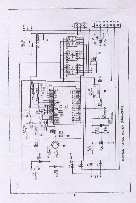
3 SECTION - 1 INTRODUCTION ISOLATED VARIABLE AC LINE SUPPLY : MODEL1506 The 1506 Isolated Variable AC Source cum leakage current tester is designed for modern electronics laboratories needing a clean, electrostatically and galvanically isolated variable line supply. The unit is designed to provide isolated output variable from 0 to 130 V AC at 4 Amps max and 0 to 260VAC at 2A max on two seperate output sockets through a range selector switch.the output voltage and load current can be monitored on a 3 digit DPM. The variable isolated output voltage capability makes this unit very convenient to use for either incoming or outgoing quality control testing. It is also useful for servicing or circuit design work, when checking operation at voltage higher or lower than normal. The unit consists of a super isolation transformer which is triple shielded from the line to protect against shock hazards. The 1506 can measure power line leakage current by means of a probe and a switch selected range of the output DPM. It can measure leakage currents upto 9.99 ma.the unit is overload protected by means of an input /output fuse. INITIAL INSPECTION Before shipping, the 1506 power supply has been tested thoroughly and found free of mechanical and electrical defects. As soon as it is unpacked, inspect for any damage that may have occurred during transit. Particular attention should be paid to the meters. Also check the packing material for any signs of severe stress (may be indicative of internal damage). Save all the packing material. Read the INSTRUCTION MANUAL carefully prior to operation. PCB Components FRONT PANEL Reference Designator Part Description = OUTPUT SOCKETS SOCKET 1 European ( 230VAC ) SOCKET 2 American ( 115VAC ) SOCKET 3 SLBR4 ( Lekage Red ) SWITCHES SW1 SW2 FUSE F1 F2 ON/OFF SPDT A/230V DPDT Toggle 6A/250V 6Amp / 250V S/B 4AMP / 250V S/B FUSE HOLDERS FH1 10Amp / 250V R3-11 FH2 10AMP / 250V R3-11 PCB Components CHASSIS Reference Designator Part Description = TRANSFORMERS T1 T2 T3 T4 T Isolation 1506 Current 1506 DPM V/4Amp Variable 1506 Voltage Sense 1 14
4 PCB Components 0893 DPM Reference Designator Part Description = CAPACITORS C1 220pf 100V ±20% CD C2 0.1µf 100V ±10% MP C3 0.01µf 100V ±20% CD C4 0.47µf, 100V ±20% CD C5 0.1µf, 50V ±10% MP C6 10µf, 35V ±20% EL C7 0.1µf, 50V ±10% MP C8 0.1µf, 50V ±20% CD C9 Not used C10 470µf, 35V ±20% EL C11 2.2µf, 50V ±20% EL * C12 47µf 50V, ±20% EL ( Additional ) * C13 0.1µf 50V, ±20% CD ( Additional ) DIODES D1 D2 D3 TO D6 TRANSISTORS/FET S Q1 Q2 Q3 IC IC1 1N4148 1N4148 1N4007 TL431 MPSA12 LM7805 ICL 7107 CPL FND S DS1 TSD566 ( Green ) DS2 TSD566 ( Green ) DS3 TSD566 ( Green ) LED S LED1 LED2 3mm GREEN Defused 3mm GREEN Defused CONNECTORS CON1 3 PIN 2.54 PITCH ( Male / Female ) CON2 ( L' Type ) 7 PIN 2.54 PITCH ( Male / Female ) 13 INPUT VOLTAGE INPUT FREQUENCY OUTPUT METERING METER ACCURACY OUTPUT-LINE ISOLATION NOISE REJECTION SECTION - 2 SPECIFICATIONS : 230V AC : 47 to 63 Hz. : I : 0 to 130 VAC at 4AMP Max. ( Available on American socket only. ) II : 0 to 260 VAC at 2AMP Max. ( Available on European socket only. ) : 3 digit DPM to read 1) Output Voltage. 2) Load Current and 3) Leakage current upto 9.99 ma. : ± 3 counts. : Capacitive coupling less than pf. : Better than 120 db ( common mode noise ). DIMENSIONS (W x H x D ) : 11.73" x 5.23" x 10.62" WEIGHT : 35 lb. approx. 2
5 SECTION - 3 DESCRIPTION INPUT AND OUTPUT TERMINATION : The unit works from 230VAC, Hz single phase supply with internal tap selection facility for 115V AC operation. The input is provided through a mains cable with a plug. The use of a three core cable enables the cabinet of the unit to be properly grounded. The unit as shipped from factory is wired for 230V /50Hz single phase supply Output is provided on two seperate sockets through a output voltage range selector switch. In one position, it provides VAC at 4 Amps max whereas in other position,it provides 0-260VAC at 2Amp.max. METERING : One 3-digit DPM is provided to measure 1) Output voltage 2) Leakage current 3) Load current Meter function is switch selectable ON-OFF SWITCH AND FUSE : The power ON-OFF switch is located on the front panel. The fuses (Input & Output) are also located on the front panel. The fuse ratings are clearly marked. PANEL CONTROLS : A voltage adjust knob allows adjustment of output AC voltage and the output voltage selector switch selects the output AC voltage range so as to provide 0-130VAC isolated output only on American socket while 0-260VAC isolated output only on European socket. Three meter function push switches are provided to select the Leakage Current or Output Voltage or Output Current (ma,v & A respectively.) to be displayed on the meter. PCB Components GLOBAL 1505 / 06 SW Reference Designator Part Description IC S IC S IC2 KA 741/ LM 741 PUSH SWITCHES SW1 TO SW3 4 Pole, 2 Way ( Interlock ) RELAY RL1 2/P 2CO 6V/6A ( OEN C ) CONNECTORS CON1 5 PIN 2.54 PITCH ( MALE / FEMALE ) CON2 7 PIN 2.54 PITCH ( MALE / FEMALE ) PCB Components 0893 DPM Reference Designator Part Description RESISTORS R1 39K, ¼W, ±5%, MFR R2 470K, ¼W, ±5%, MFR R3 1ME, ¼W, ±5%, MFR R4 SEL, ¼W, ±5%, MFR R5 2.4K, ¼W, ±5%, MFR R6 2.7K, ¼W, ±5%, MFR R7 30K, ¼W, ±5%, MFR R8 8.2K, ¼W, ±5%, MFR R9 100E, ¼W, ±5%, MFR R10 12K, ¼W, ±5%, MFR R11 20K, ¼W, ±5%, MFR R12 100E, ¼W, ±5%, MFR R13 330E, ¼W, ±5%, MFR R14 Not in Use PRESETS PR1 2.2K Horizontal 3 12
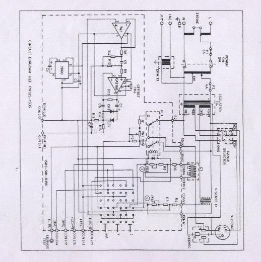
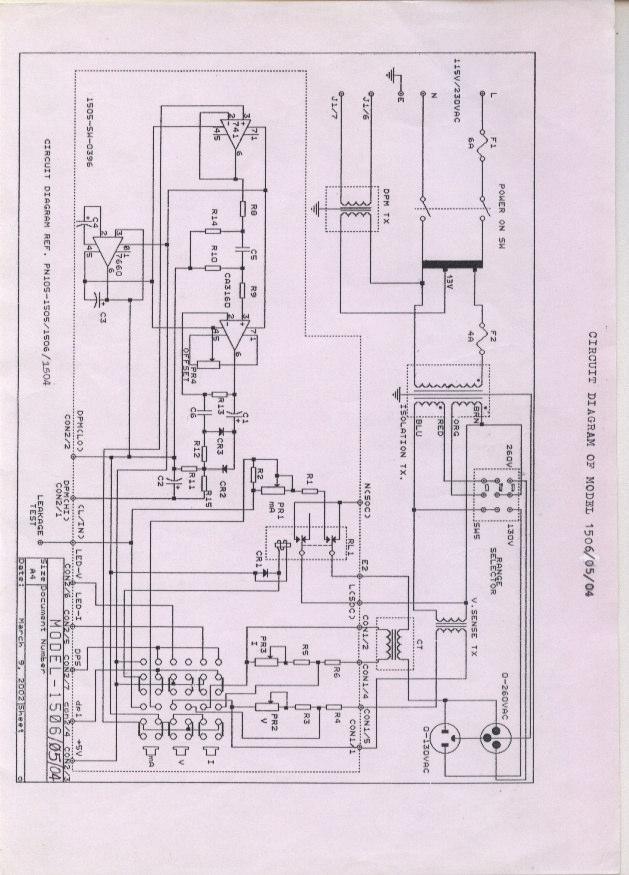
6 SECTION - 7 PART LIST PCB Components GLOBAL 1505 / 06 SW Reference Designator Part Description RESISTORS R1 R2 R3 R4 R5 R6 R7 R8 R9 R10 R11 R12 R13 R15 1.5K, ¼W ±5% MFR 120E, ¼W ±5% MFR 10K, ¼W ±5% MFR 62K, ¼W ±5% MFR 10 ohm, ¼W ±5% MFR 220 ohm, ¼W ±5% MFR Not Used 10K, ¼W ±5% MFR 100K, ¼W ±5% MFR 10M, ¼W ±5% MFR 4.7K, ¼W ±5% MFR 10K, ¼W ±5% MFR 1.2M, ¼W ±5% MFR 470K, ¼W ±5% MFR CIRCUIT DESCRIPTION : The circuit uses a step down tranformer to provide step down supply to a single phase variable autotransformer to obtain an output voltage variable from 0 to 130VAC. This is followed by a triple shielded isolation transformer which provides an output voltage from 0-130VAC or 0-260VAC electrostatic and galvanic isolation. Multiple shielding technique reduces primary to secondary static coupling to below pF. The DC isolation is over 1000 M Ohms. CAPACITORS C1 C2 C3 C4 C5 C6 1µf, 50V ±20%, ELEC 1µf, 50V ±20%, ELEC 220µf, 16V ±20%, ELEC 220µf, 50V ±20%, ELEC 0.1µf, 100V ±10%, MP 0.22µf, 100V ±10%, MP PRESETS PR1 100E Horizontal PR2 100E Horizontal PR3 100E Horizontal PR4 10K Horizontal DIODES CR1 CR2 CR1 1N4007 1N4148 1N
7 SECTION - 4 OPERATING INSTRUCTIONS a) 1506 as Isolated Variable AC Supply. Set output voltage to 0 volt by turning the 'Set Voltage' knob to minimum position. Press push button switch marked 'V' Keep the output voltage selector switch to the desired range (0-130V or 0-260V). Isolated variable voltage will be available at the respective output socket only. Switch "POWER"ON. Adjust the voltage control knob till the desired voltage is indicated on the 3-digit DPM.Connect the load at the output. Press push switch marked 'A'.The DPM will now read the load current. The total load current should not exceed the maximum rating indicated for each range. LEAKAGE CURRENT CALIBRATION 9) Set output voltage to zero volt s by turning the Voltage knob to minimum position. 10) Press push switch marked ' V ' 11) Switch on the power.adjust output voltage to 130VAC. 12) Press push switch marked ' ma '. now DPM will read leakage current. 13) Connect 25 Kohm (aprox.1w) resistor across banana socket,marked 'LEAKAGE TEST', & live point of output socket. Adjust preset PR1on switch pcb so that DPM reading is 5.00mA b) 1506 as Line Leakage Tester. Set output voltage to 0 volt by turning the knob to minimum position. Press push switch marked V. switch "POWER" ON. Adjust the voltage control till the desired voltage at which leakage current is to be measured is available at the output socket. Now press push switch marked ma. Connect unit under test (U. U. T) to output socket. Connect the leakage test probe at the socket marked 'Leakage Test'. Connect the other end of the leakage test probe to the chassis of the unit under test. Depending on the leakage,the DPM will read the leakage current. 5 10
8 SECTION - 6 CALIBRATION PROCEDURE FOR MODEL ) Keep the Voltage knob to minimum position(ccw). Press push switch marked ' V ' 2) Switch on the power. 3) Set reference voltage of DPM(pin no. 36 of U1-7107) to 1.00Volt by adjusting the preset VR1 on DPM pcb. 4) Set voltage at pin no. 6 of IC3 (CA3160) to zero Volts with the help of preset PR4 on switch pcb. VOLTAGE CALIBRATION 5) Set desired output voltage by turning Voltage knob in clockwise direction.connect external AC voltmeter at the output. 6) Adjust preset PR2 on switch pcb so that DPM reading matches with external AC Voltmeter. CURRENT CALIBRATION 7) Press push switch marked ' A '. Connect load at the output with AC current meter in series with the load.the DPM will now read the load current.(the load current should not exceed 2 Amps/4Amps for Range A/B respectively.) 8) Adjust preset PR3 on switch pcb so that the DPM reading matches with external AC current meter SECTION - 5 SERVICE AND WARRANTY INFORMATION FACTORY SERVICE AND REPAIR Global Specialties will service and repair this instrument free of charge for a period of one full year, subject to the warranty conditions stated below. To obtain a return merchandise authorisation (RMA) required for all returns, phone our Customer Service Department for a RMA and all shipping instructions : GLOBAL SPECIALTIES Savi Ranch Parkway, Yorba linda, CA 92887, WARRANTY Global Specialties warrants this device to be free from defective material or workmanship for a period of one full year from the date of original purchase. Global Specialties under this warranty is limited to repairing the defective device when returned to the factory, shipping charges prepaid, within one full year from the date of original purchase. Units returned to Global Specialities that have been subject to abuse, misuse damage or accident, or have been connected, installed or adjusted contrary to the instructions furnished by Global Specialities, or that have been repaired by unauthorized persons will not be covered by this warranty. Global Specialities reserves the right to discontinue models, change specifications price or design of this device at any time without incurring any obligation whatsoever. 9 6
9 The purchaser agrees to assume all liabilities for any damages and/or bodily injury which may result from the use or misuse of this device by the purchaser, his employees or agents. This warranty is in lieu of all other representations or warranties expressed or implied and no agent or representative of Global Specialties is authorized to assume any other obligation in connection with the sale and purchase of this device. Specifications subject to change without notice. Copyright 1994, INTERPLEX ELECTRONICS, INC, Unit No.2, Highland Industrial Centre 1486, Highland Avenue, Cheshire CT 06410, U.S.A. and TM trademarks are the property of INTERPLEX ELECTRONICS, INC, Unit No.2, Highland Industrial Centre 1486, Highland Avenue, Cheshire CT 06410, U.S.A. MAINTENANCE AND RECALIBRATION ADJUSTMENTS All circutry is factory-calibrated. No user adjustments are required. FUSE REPLACEMENT Remove the line cord from the AC outlet before changing fuses. Using a screwdriver, remove the fuse holder cap. Replace the fuse with another fuse of identical type and current rating. Replace the fuse holder cap. CASE DISASSEMBLY AND ASSEMBLY WARNING Potentially lethal AC power is present whenever the line cord is plugged into the AC outlet, even when the power switch is OFF. Always disconnect the power cord when opening the case. Avoid touching the fuse post on the inside of the unit. Should access to the inside of the unit be required, proceed a follows: 1. Remove the line cord from the AC outlet before disassembly. 2. To disassemble the case, remove the screws that secure the cover to the chassis and lift the cover off. 3. To reassemble the case, place the cover on the chassis, line up the screw holes, and replace the screws. 7 8
10
11
12
13 SERVICE AND WARRANTY INFORMATION For up-to-date product information, please visit For instructions on how to obtain a return merchandise authorization number (RMA), please visit our website, or call our customer service department. GLOBAL SPECIALTIES Savi Ranch Parkway Yorba Linda, CA globalspecialties.com Global Specialties will service and repair this instrument free of charge for a period of 3 full years, subject to the warranty conditions below. WARRANTY Global Specialties warrants the PB-503 to be free from defective material or workmanship for a period of 3 full years from date of original purchase. Under this warranty, Global Specialties is limited to repairing the defective device when returned to the factory, shipping charges prepaid, within 3 full years from date of original purchase. Units returned to Global Specialties that have been subject to abuse, misuse, damage or accident, or have been connected, installed or adjusted contrary to the instructions furnished by Global Specialties, or that have been repaired by unauthorized persons will not be covered by this warranty. Global Specialties reserves the right to discontinue models, change specifications, price or design of this device at any time without notice and without incurring any obligation whatsoever. The purchaser agrees to assume all liabilities for any damages and/or bodily injury which may result from the use or misuse of this device by the purchaser, his employees, or agents. This warranty is in lieu of all other representations or warranties expressed or implied and no agent or representative of Global Specialties is authorized to assume any other obligation in connection with the sale and purchase of this device. All rights reserved. No Part of this book shall be reproduced, stored in a retrieval system, or transmitted by any means, electronic, mechanical, photocopying recording, or otherwise, without written permission from the publisher. No patent liability is assumed with respect to the use of the information contained herein. While every precaution has been taken in the preparation of this book, the publisher assumes no responsibility for errors or omissions. Neither is any liability assumed for damages resulting from the use of the information contained herein.
2001A. 200KHz Function Generator Instruction Manual. 99 Washington Street Melrose, MA Phone Toll Free
 2001A 200KHz Function Generator Instruction Manual 99 Washington Street Melrose, MA 02176 Phone 781-665-1400 Toll Free 1-800-517-8431 Visit us at www.testequipmentdepot.com WARRANTY Global Specialties
PB-500. Analog Circuits Trainer Instruction Manual
 PB-500 Analog Circuits Trainer Instruction Manual 10/2009 99 Washington Street Melrose, MA 02176 Phone 781-665-1400 Toll Free 1-800-517-8431 Visit us at www.testequipmentdepot.com 2 All rights reserved.
Model 7000 Low Noise Differential Preamplifier
 Model 7000 Low Noise Differential Preamplifier Operating Manual Service and Warranty Krohn-Hite Instruments are designed and manufactured in accordance with sound engineering practices and should give
INSTRUCTION MANUAL LKG 601 Electrical Safety Analyzer
 INSTRUCTION MANUAL LKG 601 Electrical Safety Analyzer 110 Toledo Street Farmingdale, NY 11735 USA http://www.netech.org 510-USER-Manual Rev3 10/29/2007 Dear User, We appreciate your purchase of the LKG
INSTRUCTION MANUAL LKG
 INSTRUCTION MANUAL LKG 610 Electrical Safety Analyzer With 10 ECG Connectors 110 Toledo Street Farmingdale, NY 11735 USA Homepage: www.netech.org Dear User, We appreciate your purchase of the LKG 610 Electrical
POWER SUPPLY MODEL XP-720. Instruction Manual ELENCO
 POWER SUPPLY MODEL XP-720 Instruction Manual ELENCO Copyright 2016, 1997 by ELENCO Electronics, Inc. All rights reserved. Revised 2016 REV-H 753270 No part of this book shall be reproduced by any means;
OPERATION & SERVICE MANUAL FOR FC 110 AC POWER SOURCE
 OPERATION & SERVICE MANUAL FOR FC 100 SERIES AC POWER SOURCE FC 110 AC POWER SOURCE VERSION 1.3, April 2001. copyright reserved. DWG No. FC00001 TABLE OF CONTENTS CHAPTER 1 INTRODUCTION... 1 1.1 GENERAL...
Model 229 Series 2 Leakage Current Tester OPERATOR S MANUAL
 Model 229 Series 2 Leakage Current Tester OPERATOR S MANUAL SIMPSON ELECTRIC COMPANY 52 Simpson Avenue Lac du Flambeau, WI 54538-99 (715) 588-3311 FAX (715) 588-3326 Printed in U.S.A. Part No. 5-11575
Warning, refer to accompanying documents.
 About this Manual To the best of our knowledge and at the time written, the information contained in this document is technically correct and the procedures accurate and adequate to operate this instrument
Instruction Manual Model M Switch, DPDT, Manual Select
 Instruction Manual Model 1582-70M Switch, DPDT, Manual Select November 2018 Rev 0 STATUS MODEL 1582 CROSS TECHNOLOGIES INC. MANUAL SELECT POWER Data, drawings, and other material contained herein are proprietary
Angular Rate Sensor. Owner's Manual
 Angular Rate Sensor Owner's Manual Part Number: ARS-C132-1A WATSON INDUSTRIES, INC. 3041 MELBY ROAD EAU CLAIRE, WI 54703 Phone: (715) 839-0628 FAX: (715) 839-8248 email: support@watson-gyro.com 1 Table
Safety. This symbol, adjacent to a terminal, indicates that, under normal use, hazardous voltages may be present.
 9305 Safety International Safety Symbols This symbol, adjacent to another symbol or terminal, indicates the user must refer to the manual for further information. This symbol, adjacent to a terminal, indicates
Model 3210C. 100 Ampere AC Current Standard. Operating Manual
 Model 3210C 100 Ampere AC Current Standard Operating Manual This page intentionally left blank. 3210C OPERATORS MANUAL Serial No. Win-man\3210C.wpd This page intentionally left blank. 3210C OPERATORS MANUAL
User s Guide. MultiView Series Digital MultiMeters Models: MV110 MV120 MV130
 User s Guide MultiView Series Digital MultiMeters Models: MV110 MV120 MV130 WARRANTY EXTECH INSTRUMENTS CORPORATION warrants this instrument to be free of defects in parts and workmanship for one year
TRANSFORMER TEST SYSTEM MODEL NUMBER TTS2.5 VERSION 1.1
 TRANSFORMER TEST SYSTEM MODEL NUMBER TTS2.5 VERSION 1.1 LO/bjf June 24, 1998 TABLE OF CONTENTS Section Number DANGER SPECIFICATIONS 1 INTRODUCTION 2 SAFETY 3 CONTROLS AND INSTRUMENTATION/FIGURE 1 4 DESCRIPTION
Model MV106J/MV116J. ±10nVdc to ±11Vdc Precision DC Voltage Standard Source. Operating Manual
 Model MV106J/MV116J ±10nVdc to ±11Vdc Precision DC Voltage Standard Source Operating Manual This page intentionally left blank. MV 106 & MV116 OPERATORS MANUAL Serial No. Win-man\mvman.wpd This page intentionally
WRM-10 TM TRANSFORMER WINDING RESISTANCE METER
 WRM-10 TM TRANSFORMER WINDING RESISTANCE METER USER S MANUAL Vanguard Instruments Company, Inc. 1520 S. Hellman Ave. Ontario, California 91761, USA TEL: (909) 923-9390 FAX: (909) 923-9391 June 2009 Revision
INSTALLATION AND MAINTENANCE MANUAL FOR GROUND MONITOR GM-250 COPYRIGHT 1983 AMERICAN MINE RESEARCH, INC.
 INSTALLATION AND MAINTENANCE MANUAL FOR GROUND MONITOR GM-250 COPYRIGHT 1983 AMERICAN MINE RESEARCH, INC. MANUAL PART NUMBER 180-0036 ORIGINAL: 1-17-83 REVISION: B (8-26-86) NOT TO BE CHANGED WITHOUT MSHA
Handheld Digital Multimeter PRO-50A
 Handheld Digital Multimeter PRO-50A Safety Summary A statement calls attention to an operating procedure, practice, or condition, which, if not followed correctly, could result in injury or death to personnel.
TRIAXIAL FLUXGATE MAGNETOMETER OWNER'S MANUAL
 TRIAXIAL FLUXGATE MAGNETOMETER OWNER'S MANUAL PART NUMBER: FGM-301 WATSON INDUSTRIES, INC. 3041 MELBY ROAD EAU CLAIRE, WI 54703 Phone: (715) 839-0628 FAX: (715) 839-8248 email: support@watson-gyro.com
User s Manual. MiniTec TM Series. Model MN26 (Model MN26T includes temperature probe) Mini Autoranging MultiMeter
 Mini Autoranging MultiMeter") User s Manual MiniTec TM Series Model MN26 (Model MN26T includes temperature probe) Mini Autoranging MultiMeter Introduction Congratulations on your purchase of Extech s MN26 Autoranging Multimeter. This
User s Manual MiniTec TM Series Model MN26 (Model MN26T includes temperature probe) Mini Autoranging MultiMeter Introduction Congratulations on your purchase of Extech s MN26 Autoranging Multimeter. This
Broadband Step-Up Transformer. User Manual
 Broadband Step-Up Transformer User Manual 990-1930 09/2004 Introduction Introduction About this unit The APC Step-Up Transformer provides 220 V power from 60 VAC Broadband cable systems. Safety Electrical
DC200A Displacement Clipper User Manual
 Trig-Tek DC200A Displacement Clipper User Manual Publication No. 980981 A Inc. 4 Goodyear, Irvine, CA 92618 Tel: (800) 722-2528, (949) 859-8999; Fax: (949) 859-7139 atsinfo@astronics.com atssales@astronics.com
PARALLEL MULTI-AMP KIT for 7200 Series AMPLIFIERS INSTRUCTION SHEET
 2 5 0 7 W a r r e n S t r e e t, E l k h a r t, I N 4 6 5 1 6 U S A 5 7 4. 2 9 5. 9 4 9 5 w w w. A E T e c h r o n. c o m PARALLEL MULTI-AMP KIT for 7200 Series AMPLIFIERS INSTRUCTION SHEET Kit Contents:
Model 1791 VHF Radio User's Manual
 Model 79 VHF Radio User's Manual ALL WEATHER INC 65 NATIONAL DRIVE SACRAMENTO, CA 95834 WWW.ALWEATHERINC.COM 79 VHF RADIO USER'S MANUAL CONTENTS INTRODUCTION... Description... Transmitter Module... Power
Model 4007DDS. 7 MHz Sweep Function Generator
 Model 4007DDS 7 MHz Sweep Function Generator 1 Model 4007DDS - Instruction Manual Limited Two-Year Warranty B&K Precision warrants to the original purchaser that its products and the component parts thereof,
DM-46 Instruction Manual
 Auto Meter Products Inc. Test Equipment DM-46 Instruction Manual Automotive Multimeter and Inductive Amp Probe The DM-46 is the auto industry s answer to pocket portability in a 20 2650-1552-00 3/8/11
200Amp AC Clamp Meter + NCV Model MA250
 User's Guide 200Amp AC Clamp Meter + NCV Model MA250 Introduction Congratulations on your purchase of this Extech MA250 Clamp Meter. This meter measures AC Current, AC/DC Voltage, Resistance, Capacitance,
Series 3000 Model R-107A
 Series 3000 Model R-107A DUAL TONE SENDER INSTRUCTION MANUAL Monroe Electronics 100 Housel Ave Lyndonville NY 14098 800-821-6001 585-765-2254 fax 585-765-9330 monroe-electronics.com Printed in USA Copyright
Harris IRT Enterprises Multi-Channel Digital Resistance Tester Model XR
 Harris IRT Enterprises Multi-Channel Digital Resistance Tester Model 6012-06XR Specifications & Dimensions 2 Theory of Operation 3 System Block Diagram 4 Operator Controls & Connectors 5 Test Connections
BC145 SIGNAL ISOLATOR BOARD
 BC145 SIGNAL ISOLATOR BOARD 4/17 Installation & Operating Manual MN1373 Any trademarks used in this manual are the property of their respective owners. Important: Be sure to check www.baldor.com to download
Model 935A. Dual Tone Sender INSTRUCTION MANUAL
 Model 935A Dual Tone Sender INSTRUCTION MANUAL Monroe Electronics 100 Housel Ave Lyndonville NY 14098 800-821-6001 585-765-2254 fax 585-765-9330 monroe-electronics.com Printed in USA Copyright Monroe Electronics,
INSTRUCTION MANUAL For LINE IMPEDANCE STABILIZATION NETWORK. Model LI khz to 10 MHz
 Page 1 of 10 INSTRUCTION MANUAL For LINE IMPEDANCE STABILIZATION NETWORK Model LI-4100 10 khz to 10 MHz Page 2 of 10 Table of Contents 1.0 Introduction... 3 2.0 Product Description... 4 3.0 Product Specifications...
HTA125A/250A. Power Amplifiers. Installation & Use Manual
 HTA125A/250A Power Amplifiers Installation & Use Manual Specifications subject to change without notice. 2010 Bogen Communications, Inc. All rights reserved. 54-5832-04B 1011 NOTICE: Every effort was made
INSTRUCTION MANUAL MODEL 4010A. 2 MHz FUNCTION GENERATOR MANUAL DE INSTRUCCIONES MODELO 4010A. 2MHz GENERADOR DE FUNCIONES
 INSTRUCTION MANUAL MANUAL DE INSTRUCCIONES MODEL 4010A MODELO 4010A 2 MHz FUNCTION GENERATOR 2MHz GENERADOR DE FUNCIONES TEST INSTRUMENT SAFETY WARNING Normal use of test equipment exposes you to a certain
34134A AC/DC DMM Current Probe. User s Guide. Publication number April 2009
 User s Guide Publication number 34134-90001 April 2009 For Safety information, Warranties, Regulatory information, and publishing information, see the pages at the back of this book. Copyright Agilent
INSTRUCTIONS PS2500 POWER SUPPLY
 INSTRUCTIONS PS2500 POWER SUPPLY The Hoefer PS 2500 Power Supply will furnished power to Constant Voltage or Constant Power modes of operation. It will accurately supply 0-2500 volts, 0-300 ma or 0-375
SPM-50 RF Spectrum Power Meter PC Software User Manual
 SPM-50 RF Spectrum Power Meter PC Software User Manual Shineway Technologies, Inc. Notices Copyright 2014, ShinewayTech, All rights reserved. No part of this manual may be reproduced in any form or by
201AP Charge Amplifier User Manual
 Trig-Tek 201AP Charge Amplifier User Manual Publication No. 980996 Rev. A Astronics Test Systems Inc. 4 Goodyear, Irvine, CA 92618 Tel: (800) 722-2528, (949) 859-8999; Fax: (949) 859-7139 atsinfo@astronics.com
P5100A & P5150 High Voltage Probes Performance Verification and Adjustments
 x P5100A & P5150 High Voltage Probes Performance Verification and Adjustments ZZZ Technical Reference *P077053001* 077-0530-01 xx P5100A & P5150 High Voltage Probes Performance Verification and Adjustments
Pen Multimeter. Model
 Pen Multimeter Model 381626 CAUTION: Read, understand and follow all Safety Rules and Operating Instructions in this manual before using this product. This instrument is a 3200 count pen style digital
An American Control Electronics Brand PCM4 SERIES USER MANUAL PCM4.
 An American Control Electronics Brand PCM4 SERIES PCM4 USER MANUAL www.minarikdrives.com Dear Valued Consumer: Congratulations on your purchase of the PCM4 Series isolation card. This User Manual was created
2015 RIGOL TECHNOLOGIES, INC.
 Service Guide DG000 Series Dual-channel Function/Arbitrary Waveform Generator Oct. 205 TECHNOLOGIES, INC. Guaranty and Declaration Copyright 203 TECHNOLOGIES, INC. All Rights Reserved. Trademark Information
Distribution Amplifiers 1
 Distribution Amplifiers 1-30dB PUT 49-750 MHz 43 db GA POWER DOUBLED P/N: 1002705 REVERSE GA M MAX DESCRIPTION The R.L. DRAKE models DA8642, DA8632,, and DA7533, are broadband distribution amplifiers designed
Keysight 16440A SMU/Pulse Generator Selector
 Keysight 16440A SMU/Pulse Generator Selector User s Guide Notices Keysight Technologies 1994-2014 No part of this manual may be reproduced in any form or by any means (including electronic storage and
DDS Function Generator
 Model: 4007B, 4013B DDS Function Generator USER MANUAL Safety Summary The following safety precautions apply to both operating and maintenance personnel and must be observed during all phases of operation,
SI-125 Power Amplifier Manual 6205 Kestrel Road; Mississauga, Ontario; Canada; L5T 2A1 November 2016, Rev 0.5
 SI-125 Power Amplifier Manual 6205 Kestrel Road; Mississauga, Ontario; Canada; L5T 2A1 November 2016, Rev 0.5 Phone: (905) 564-0801 Fax: (905) 564-0806 www.telecor.com E:\T2-108\T2-M108-ABC\T2-M108-B.doc/AD
DM-46 Instruction Manual
 Test Equipment Auto Meter Products Inc. 413 West Elm Street Sycamore, IL 60178 Service (815) 899-0801 Toll Free (866) 883-TEST (8378) www.autometer.com/test DM-46 Instruction Manual Automotive Multimeter
CD770 DIGITAL MULTIMETER INSTRUCTION MANUAL
 CD770 DIGITAL MULTIMETER INSTRUCTION MANUAL Table of Contents 1 SAFETY PRECAUTIONS Before use, read the following safety precautions.- 1-1 Explanation of Warning Symbols 001 1-2 Warning Messages for Safe
HydroLynx Systems, Inc.
 Model 50386R-RP Receiver and Repeater Instruction Manual Document No: A102684 Document Revision Date: August, 2006 Receiving and Unpacking Carefully unpack all components and compare to the packing list.
User s Guide. 400A AC/DC Clamp Meter. Model MA220
 User s Guide 400A AC/DC Clamp Meter Model MA220 Introduction Thank you for selecting the Extech MA200 AC/DC Clamp Meter. This meter measures AC/DC Current, AC/DC Voltage, Resistance, Capacitance, Frequency,
Amplifier Series BASIC. Installation & Operations Manual
 Amplifier Series BASIC Installation & Operations Manual Bittner-Audio 200 Power Amplifier Series BASIC Bittner - Audio September 200 200 Bittner-Audio. All Rights Reserved. Bittner-Audio reserves specification
41P Portable Calibrator User Manual
 Trig-Tek 41P Portable Calibrator User Manual Publication No. 980961 Rev. A Astronics Test Systems Inc. 4 Goodyear, Irvine, CA 92618 Tel: (800) 722-2528, (949) 859-8999; Fax: (949) 859-7139 atsinfo@astronics.com
AMERITRON RCS-12 AUTOMATIC ANTENNA SWITCH
 AMERITRON RCS-12 AUTOMATIC ANTENNA SWITCH INSTRUCTION MANUAL PLEASE READ THIS MANUAL BEFORE OPERATING THIS EQUIPMENT! 116 Willow Road Starkville, MS 39759 USA 662-323-8211 Version 3B Printed in U.S.A.
INSTRUCTION MANUAL FOR EIDS/S POWER SUPPLY
 INSTRUCTION MANUAL FOR EIDS/S POWER SUPPLY -0?.1'08 MODEL /0-4o- (- I) --.l- r). SERIAL NO. 9 IC ~ J..3 g L ( (201) 922-9300 ELECTRONIC MEASUREMENTS INC. 405 ESSEX ROAD, NEPTUNE, N.J. 07753 0,tJ, Ctl-f0
R-F Skewed Hybrids. Type H1SB and H1SB-R. & R-F Balanced Hybrids Type H1R, H3X and Type H1RB, H3XB and Type H1RB-40. System Manual CH44 VER03
 R-F Skewed Hybrids Type H1SB and H1SB-R & R-F Balanced Hybrids Type H1R, H3X and Type H1RB, H3XB and Type H1RB-40 System Manual CH44 VER03 (Replaces CH44-VER02) AMETEK Power Instruments 4050 NW 121st Avenue
DANFYSIK A/S - DK-4040 JYLLINGE - DENMARK
 2 TABLE OF CONTENTS PAGE 1. INTRODUCTION AND SPECIFICATIONS. 1.1 Introduction... 4 1.1.1 Working principle....4 1.2 Warranty...5 2. RECEIVING AND UNPACKING. 2.1 Receiving the goods....6 2.2 Instructions
USER MANUAL MODEL Parallel to Serial/ Serial to Parallel Interface Converter
 USER MANUAL MODEL 2029 Parallel to Serial/ Serial to Parallel Interface Converter C E R T I F I E D An ISO-9001 Certified Company Part #07M2029-B, Rev. C Doc. #102011UB Revised 6/16/09 SALES OFFICE (301)
Advanced Test Equipment Rentals ATEC (2832)
") Established 1981 Advanced Test Equipment Rentals www.atecorp.com 800-404-ATEC (2832) A.H. Systems Model Active Monopole Antennas Active Monopole Antenna Series Operation Manual 1 TABLE OF CONTENTS INTRODUCTION
Established 1981 Advanced Test Equipment Rentals www.atecorp.com 800-404-ATEC (2832) A.H. Systems Model Active Monopole Antennas Active Monopole Antenna Series Operation Manual 1 TABLE OF CONTENTS INTRODUCTION
AMP SELECTOR Owner s Manual
 AMP SELECTOR Owner s Manual Version 1.0 VOODOO LAB AMP SELECTOR User s Manual Introduction The Voodoo Lab Amp Selector is the ultimate stand-alone tool for switching your guitar into multiple amplifiers.
PCO-7114 Laser Diode Driver Module Operation Manual
 PCO-7114 Laser Diode Driver Module Operation Manual Directed Energy, Inc. 1609 Oakridge Dr., Suite 100, Fort Collins, CO 80525, (970) 493-1901 sales@ixyscolorado.com www.ixyscolorado.com Manual Document
200B Clipper Module User Manual
 Trig-Tek 200B Clipper Module User Manual Publication No. 980954 Rev. A Astronics Test Systems Inc. 4 Goodyear, Irvine, CA 92618 Tel: (800) 722-2528, (949) 859-8999; Fax: (949) 859-7139 atsinfo@astronics.com
KeyPre KP6 - Electronic Instrument Preamplifier
 ! USE ONLY WITH 250V FUSE KeyPre KP6 - Electronic Instrument Preamplifier USER S GUIDE 0 10dB 0 10dB 0 10dB 0 10dB 0dB 10dB 0 10dB AVEDIS AUDIO E L E C T R O N I C S AC INPUT 100-240VAC 50/60 Hz 1.1" 1.225"
7I25 H-BRIDGE MANUAL
 7I25 H-BRIDGE MANUAL VERSION 1.0 Copyright 2002 by MESA ELECTRONICS Richmond, CA. Printed in the United States of America. All rights reserved. This document and the data disclosed herein is not to be
BLD75-1. Bilevel Step Motor Driver. User s Guide. #L010125
 BLD75-1 Bilevel Step Motor Driver User s Guide A N A H E I M A U T O M A T I O N #L010125 1 Features Unipolar Operation 10 Amps per Phase Operating Current (Kick Current) 7 Amps per Phase Standstill Current
EXECUTE Shiloh Road Alpharetta, Georgia (770) FAX (770) Toll Free
 FAX (770) Toll Free") Instruction Manual Model 1586-06 RF Attenuator May 2009 Rev A 1 2 3 12.5 53.5 16.3 MODEL 1586 RF ATTENUATOR CROSS TECHNOLOGIES INC. EXECUTE PS1 PS2 Data, drawings, and other material contained herein are
Instruction Manual Model 1586-06 RF Attenuator May 2009 Rev A 1 2 3 12.5 53.5 16.3 MODEL 1586 RF ATTENUATOR CROSS TECHNOLOGIES INC. EXECUTE PS1 PS2 Data, drawings, and other material contained herein are
O. S. WALKER MICROPROCESSOR CHUCK CONTROL MODEL MSB SERIES TABLE OF CONTENTS
 O. S. WALKER MICROPROCESSOR CHUCK CONTROL MODEL MSB SERIES TABLE OF CONTENTS PAGE 1-3 OPERATING INSTRUCTIONS 4 DEMAG CYCLE STEPS 5 INSTALLATION INSTRUCTIONS 6 SPECIFICATIONS 7 & 8 DIMENSIONAL DIAGRAMS
45EMD Portable Calibrator User Manual
 Trig-Tek 45EMD Portable Calibrator User Manual Publication No. 980958 Rev. B Astronics Test Systems Inc. 4 Goodyear, Irvine, CA 92618 Tel: (800) 722-2528, (949) 859-8999; Fax: (949) 859-7139 atsinfo@astronics.com
INSTALLATION AND OPERATING INSTRUCTIONS MODEL SIVF. KB Part No Signal Isolator for KBVF Controls. See Page 1 Pending
 INSTALLATION AND OPERATING INSTRUCTIONS MODEL SIVF KB Part No. 9474 Signal Isolator for KBVF Controls See Page 1 Pending See Safety Warning on Page 1 The information contained in this manual is intended
AMP-12 OPERATOR S MANUAL
 AMP-12 OPERATOR S MANUAL Version 1.0 Copyright 2002 by Vatell Corporation Vatell Corporation P.O. Box 66 Christiansburg, VA 24068 Phone: (540) 961-3576 Fax: (540) 953-3010 WARNING: Read instructions carefully
Warning, refer to accompanying documents V CAT II Overvoltage category II device. CSA Canadian Standards Association
 About this Manual To the best of our knowledge and at the time written, the information contained in this document is technically correct and the procedures accurate and adequate to operate this instrument
USER MANUAL. Maxwell Technologies BOOSTCAP Energy Storage Modules. User Manual for 15V Modules: 20 F, 23 F, 53 F, 58 F 15 Volts DC
 USER MANUAL Maxwell Technologies BOOSTCAP Energy Storage Modules User Manual for 15V Modules: 20 F, 23 F, 53 F, 58 F 15 Volts DC BPAK0020 P015 B1 BPAK0023 E015 B1 BPAK0052 P015 B1 BPAK0052 P015 B2 BPAK0058
P5100A & P5150 High Voltage Probes Performance Verification and Adjustments
 x P5100A & P5150 High Voltage Probes Performance Verification and Adjustments ZZZ Technical Reference *P077053002* 077-0530-02 xx P5100A & P5150 High Voltage Probes Performance Verification and Adjustments
ALS. Advanced Test Equipment Rentals ATEC (2832) FOR SERVICE CALL ADVANCED TEST EQUIPMENT SERVICE
 FOR SERVICE CALL ADVANCED TEST EQUIPMENT SERVICE") Established 1981 Advanced Test Equipment Rentals www.atecorp.com 800-404-ATEC (2832) ALS RENT - SELL REPAIR & CALIBRATION SERVICE ELECTRONIC EQUIPMENT FOR SERVICE CALL ADVANCED TEST EQUIPMENT SERVICE 1-800-404-2832
Established 1981 Advanced Test Equipment Rentals www.atecorp.com 800-404-ATEC (2832) ALS RENT - SELL REPAIR & CALIBRATION SERVICE ELECTRONIC EQUIPMENT FOR SERVICE CALL ADVANCED TEST EQUIPMENT SERVICE 1-800-404-2832
Model 228 Current Leakage Tester INSTRUCTION MANUAL
 Model 228 Current Leakage Tester INSTRUCTION MANUAL 1 About this Manual To the best of our knowledge and at the time written, the information contained in this document is technically correct and the procedures
CMP-300 Composite Mixer/ Distribution Amplifier
 Broadcast Devices, Inc. CMP00 Composite Mixer/ Distribution Amplifier TECHNICAL REFERENCE MANUAL Broadcast Devices, Inc. Crestview Avenue Cortlandt Manor, NY 0 Tel. (9) 0 Fax. (9) 9 REV: A 0/0 Table of
OPERATOR S MANUAL Model 160 Volt-Ohm-Milliammeter
 OPERATOR S MANUAL Model 160 Volt-Ohm-Milliammeter About this Manual To the best of our knowledge and at the time written, the information contained in this document is technically correct and the procedures
Operator s Manual. PP016 Passive Probe
 Operator s Manual PP016 Passive Probe 2017 Teledyne LeCroy, Inc. All rights reserved. Unauthorized duplication of Teledyne LeCroy documentation materials is strictly prohibited. Customers are permitted
Copyright 2014 by Minarik Drives
 Copyright 2014 by Minarik Drives All rights reserved. No part of this document may be reproduced or transmitted in any form without written permission from Minarik Drives. The information and technical
VT1586A Rack Mount Terminal Panel Installation and User s Manual
 VT1586A Rack Mount Terminal Panel Installation and User s Manual Manual Part Number: 82-0095-000 Rev. June 16, 2003 Printed in U.S.A. Certification VXI Technology, Inc. certifies that this product met
MODEL W Power Amplifier
 TEGAM, INC. MODEL 2348 18.75 W Power Amplifier This owner s manual was as current as possible when this product was manufactured. However, products are constantly being updated and improved. Because of
Model 1737 Dual Range DC Power Supply
 Model 1737 Dual Range DC Power Supply INSTRUCTION MANUAL 1 Safety Summary The following safety precautions apply to both operating and maintenance personnel and must be observed during all phases of operation,
Glass Electrode Meter
 Glass Electrode Meter INSTRUCTION MANUAL FOR Glass Electrode R/C Meter MODEL 2700 Serial # Date PO Box 850 Carlsborg, WA 98324 U.S.A. 360-683-8300 800-426-1306 FAX: 360-683-3525 http://www.a-msystems.com
PA WATT PORTABLE PA SYSTEM PRODUCT MANUAL
 PA-5150 5 150-WATT PORTABLE PA SYSTEM PRODUCT MANUAL THANK YOU FOR CHOOSING POLSEN. The Polsen PA-5150 is an active PA system that s ideal for solo performers or vocalists. It can be used as a PA system
TEGAM, INC. SINGLE/DUAL CHANNEL HIGH VOLTAGE AMPLIFIER MODEL 2340/2350. Instruction Manual PN# CD Publication Date: June 2006 REV.
 TEGAM, INC. SINGLE/DUAL CHANNEL HIGH VOLTAGE AMPLIFIER MODEL 2340/2350 Instruction Manual PN# 810044-CD Publication Date: June 2006 REV. C This owner s manual was as current as possible when this product
DCS-E 1kW Series DC Power Supplies
 DCS-E 1kW Series DC Power Supplies Operation Manual This manual covers models: DCS8-125E DCS60-18E DCS10-100E DCS80-13E DCS20-50E DCS100-10E DCS33-33E DCS150-7E DCS40-25E DCS300-3.5E DCS50-20E DCS600-1.7E
FarmPS-1 Table of Contents
 Copyright 2004 Grandad s Electronics Seattle, Washington, USA INSTRUCTION MANUAL Model FarmPS-1, 1.5V/90V Farm Radio Power Supply A- A+ FarmPS-1 Table of Contents Section Page Contents 1.0.............................
INSTRUCTION MANUAL. March 11, 2003, Revision 3
 INSTRUCTION MANUAL Model 701A Stimulator March 11, 2003, Revision 3 Copyright 2003 Aurora Scientific Inc. Aurora Scientific Inc. 360 Industrial Parkway S., Unit 4 Aurora, Ontario, Canada L4G 3V7 Tel: 1-905-727-5161
Digital Lighting Systems, Inc.
 PD408-AN0-277 ANALOG 0-0 V 0-0V analog control 4 Channel x 2250 W Dimmer & Switch Packs 220/240/277 Volts operation PD408-AN0-277 4 circuit Analog -0V 4 x 8 A. Dimmer pack Serial Number Digital Lighting
User s Guide. Agilent 16441A R-Box. Agilent Part No Printed in Japan January Edition 4
 User s Guide Agilent 16441A R-Box Agilent Part No. 16441-90000 Printed in Japan January 2000 Edition 4 Legal Notice The information contained in this document is subject to change without notice. Copyright
DIGITAL / ANALOG TRAINER
 DIGITAL / ANALOG TRAINER MODEL XK-150 A COMPLETE MINI-LAB FOR BUILDING, TESTING AND PROTOTYPING ANALOG AND DIGITAL CIRCUITS Instruction Manual ELENCO Copyright 2016, 1998 by ELENCO Electronics, Inc. All
WireMaster Coax BNC PN: Rev C 2/13
 WireMaster Coax BNC Instruction Manual PN: 3274 84-868 Rev C 2/13 Table of Contents Features...... 2 Introduction... 3 Warnings and Cautions... 3 Specifications...4 Typical Cable/Wire Resistances...5 Control
Type Contact form Plug-in/solder Plug-in/solder PCB terminals Upper-mounting terminals terminals with plug-in/solder
 A Miniature Power Relay Equipped with arc barrier. Dielectric strength: 2,000 V. Built-in diode models added to the LY Series. Single-pole and double-pole models are applicable to operating coils with
Instruction Manual. Model 1856D 3.7GHz Frequency Counter
 Instruction Manual Model 1856D 3.7GHz Frequency Counter WARRANTY Warranty service covers a period of one year from the date of original purchase. In case of technical failure within one year, repair service
Model 935A Current Source Operation Manual
 Model 935A Current Source Operation Manual Arbiter Systems, Inc. Paso Robles, CA 93446 U.S.A. ii Description This manual is issued for reference only, at the convenience of Arbiter Systems. Reasonable
PB-503 DESKTOP ANALOG & DIGITAL DESIGN TRAINER. User Manual
 PB-503 DESKTOP ANALOG & DIGITAL DESIGN TRAINER User Manual Test Equipment Depot - 800.517.8431-99 Washington Street Melrose, MA 02176 1 INTRODUCTION TestEquipmentDepot.com The PB-503 Analog/Digital Electronic
Oberebenestrasse Bremgarten Switzerland Tel Fax
 Oberebenestrasse 11 5620 Bremgarten Switzerland Tel. +41 56 640 06 70 Fax. +41 56 640 06 74 Single Phase - Battery Operated Automatic Transformer Turns Ratiometer Test System Model: TR-1 Model: TR-1P Instruction
Autoranging Multimeter Extech EX503
 User's Guide Autoranging Multimeter Extech EX503 Introduction Congratulations on your purchase of the Extech EX503 Autoranging Multimeter. This meter measures AC/DC Voltage, AC/DC Current, Resistance,
Model 1792 VHF Radio. User s Manual. Rev. B FAA APPROVED NOT FAA APPROVED. ECP Dec 30
 Model 1792 VHF Radio FAA APPROVED ECP202 2014 Dec 30 NOT FAA APPROVED User s Manual Rev. B All Weather Inc. 1165 National Drive Sacramento, CA 95834 USA 800.824.5873 www.allweatherinc.com Copyright 2011,
TABLE OF CONTENTS. 1) Introduction 2. 2) Unpacking your preamplifier 2. 3) Installing the preamp into your system 3
 Introduction 2. 2) Unpacking your preamplifier 2. 3) Installing the preamp into your system 3") TABLE OF CONTENTS 1) Introduction 2 2) Unpacking your preamplifier 2 3) Installing the preamp into your system 3 4) Operation of your preamplifier 6 5) Troubleshooting 8 6) Registration of your preamplifier
TABLE OF CONTENTS 1) Introduction 2 2) Unpacking your preamplifier 2 3) Installing the preamp into your system 3 4) Operation of your preamplifier 6 5) Troubleshooting 8 6) Registration of your preamplifier