User Manual. A3930 Enterprise Gateway
|
|
|
- Belinda Dawson
- 5 years ago
- Views:
Transcription


1 User Manual A3930 Enterprise Gateway 1
2 Legal Notices Copyright 2018 Windrock Incorporated. All rights reserved. No part of this manual may be reproduced or transmitted in any form or by any mean without the written permission from Windrock Incorporated. Software and Firmware License Notice Your license agreement with Windrock Incorporated authorizes the number of copies which can be made and the computer systems on which they may be used. Any unauthorized duplication or use of Windrock software or firmware in whole or in part, in print, or in any other storage and retrieval system, is forbidden. Disclaimer The manual is provided for informational purposes. Windrock Incorporated makes no warranty of any kind with regard to this material, including, but not limited to, the implied warranties of merchantability and fitness for a particular purpose. Windrock Incorporated shall not be liable for errors, omissions, or inconsistencies which may be contained herein or for incidental or consequential damages in connection with the furnishing, performance, or use of this material. Information in this document is subject to change without notice and does not represent a commitment on the part of Windrock Incorporated. Any software described in this document is furnished under a license agreement or nondisclosure agreement. The software may be used or copied only in accordance with the terms of the agreement. Important Safety Notices When used in accordance with the instructions in this manual and the associated control drawings, Windrock Spotlight is approved for use in Class 1 Division 2 and unclassified areas. Failure to follow this manual may result in an explosion hazard when used in hazardous locations or improper operation. The examples and diagrams in this manual are included for illustrative purposes. Because of the many variables and requirements associated with any particular installation, Windrock Inc. cannot assume responsibility or liability for actual use based upon examples and diagrams. For any questions, problems, or service for any Windrock products, including Windrock Spotlight, visit the Windrock web site at Inquiries may also be directed to support@windrock.com or Windrock, Inc 1832 Midpark Drive, Suite 102 Knoxville, TN
3 Table of Contents 1 A3930 Windrock Spotlight Gateway Connections Indicators Operation Included Accessories General Gateway WiFi Antennas Gateway LTE Antennas System Installation General Hazardous Locations On-site Assembly Installation Overview Gateway Mounting Gateway Power Requirements Environment Maintenance and Cleaning Specifications Appendix Gateway Mounting Options Gateway Control Drawing

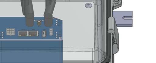
4 1 A3930 Windrock Spotlight Gateway THE A3930 CONTAINS NO USER SERVICEABLE COMPONENTS. ANY ATTEMPT TO MODIFY THIS DEVICE, USE FOR OTHER THAN ITS INTENDED PURPOSE, OR SUBSTITUTION OF COMPONENTS MAY DAMAGE THIS DEVICE LEADING TO UNRELIABLE OPERATION AND DECREASED PROTECTION FOR THE DEVICE BEING MONITORED. LA A3930 NE CONTIENT AUCUNS RÉPARABLE. TOUTE TENTATIVE DE MODIFICATION DE CET APPAREIL, UTILISER POUR LES AUTRES QUE SA DESTINATION, OU LA SUBSTITUTION DE COMPOSANTS PEUT ENDOMMAGER CET APPAREIL MENANT À PEU FIABLE, OPÉRATION ET UNE DIMINUTION DE PROTECTION POUR LE DISPOSITIF SURVEILLÉ. 1.1 Connections The A3930 Enterprise Gateway (Fig. 1-1) uses the B+B SmartWorx router by Advantech. This router utilizes two (2) 4G LTE Antennas to communicate to the cellular network. There is one (1) WiFi Antenna connection for direct communication to WiFi enabled Windrock devices, such as the Spotlight Controller. The unit operates on a low voltage DC supply, exact specifications are shown in Section 5. Figure 1-1, A3630 Gateway A universal SIM card has been installed in the Enterprise Gateway. This SIM card has been pre-configured with the ability to communicate with most big cellular providers, thus making it easier to connect to the cloud than traditional methods. To prevent damage during shipping, the router and antennas are packaged separately. See Section 3 for details on assembly. External WiFi and LTE cable assemblies have been tied off to the side of the enclosure. If signal strength is an issue, these cable assemblies can be connected to the router for external access. 4G LTE Antenna The industrial router has two RP-SMA Female Jack (Female Socket) Connectors that are used to connect the cellular antenna. WiFi Antenna The industrial router unit has one RP-SMA Female Jack (Male Pin) Connector used to connect the WiFi Antenna. Power Input - Power is applied via the integral power cable.. NOTE: EQUIPMENT SHALL BE POWERED BY AN APPROVED SELV LPS POWER SOURCE. Power connection and mounting requirements are both detailed in Section Indicators WARNING EXPLOSION HAZARD DO NOT DISCONNECT EQUIPMENT UNLESS POWER HAS BEEN SWITCHED OFF OR THE AREA IS KNOWN TO BE NON-HAZARDOUS. ADVERTISSEMENT RIAQUE D EXPLOSION AVANT DE DECONNECTOR L EQUIPMENT, COUPER LE COURENT OU S ASSURER QUE L EMPLACEMENT EST DESIGNE NON DANGEREUX. There are nine LED indicators located on the front of the router to provide router status. Only four of the nine are important in this application, refer to Table 1-2. Under normal operation, the router will have a green PWR and SIM LED. Ideally, the router will indicate a Strong or Adequate WAN LED pattern frequency, based on the last 10 seconds of cellular network connectivity. 4
 The second SIM card is active (Not Typical) WAN Yellow LED goes out 1x per one sec. Signal strength is from -50dBm to -69 dbm (Strong signal) LED goes out 1x per two sec.")
5 Label LED Color State Description PWR Green Blinking Router is ready On Fast Blinking Starting of the router Updating firmware SIM Green On (Green color) The first SIM card is active Yellow On (Yellow color) The second SIM card is active (Not Typical) WAN Yellow LED goes out 1x per one sec. Signal strength is from -50dBm to -69 dbm (Strong signal) LED goes out 1x per two sec. LED goes out 1x per five sec. Signal strength is from -70dBm to -89 dbm (Adequate signal) Signal strength is from -90dBm to -113 dbm (Marginal signal) DAT Red Blinking Communication in progress on radio channel 1.3 Operation Table 1-2. Status Indication Once installed and initial operation has been verified, long-term user interaction with the A3930 is not required. When applying initial power to the Gateway, the installer should verify proper operation by using a mobile device and connecting to the WiFi network. For specific details, refer to the associated Windrock IIoT product User Manual (i.e. Spotlight User Manual). WARNING: If A3930 is not operating properly, then unit must be returned to Windrock for repair service. Contact your sales representative or Windrock directly. AVERTISSEMENT : Si A3930 ne fonctionne pas correctement, puis doit être renvoyé à Windrock des réparations. Contactez votre représentant commercial ou Windrock directement 2 Included Accessories 2.1 General Spotlight systems have ONLY been approved for use using the accessories listed in the following section. NOTE: THE SAFETY OF ANY SYSTEM INCORPORATING THE EQUIPMENT IS THE RESPONSIBILITY OF THE INSTALLER OF THE SYSTEM. IF THE EQUIPMENT IS USED IN A MANNER NOT SPECIFIED BY THE MANUFACTURER, THE PROTECTION PROVIDED BY THE EQUIPMENT MAY BE IMPAIRED. 2.2 Gateway WiFi Antennas Letter Part Router Connection A WiFi Antenna WiFi B Cellular LTE Antenna DIV C Cellular LTE Antenna ANT D Internal Power Cable PWR E External Cellular LTE Antenna Connection (Not Typically Used) DIV F External WiFi Antenna Connection (Not Typically Used) WiFi G External Ethernet Connection (Not Typically Used) LAN H External Cellular LTE Antenna (Not Typically Used) ANT I External Power Cable - Figure 2-1, Gateway Connections The Gateway uses one WiFi antenna as shown in Figure 2-1. This 90 hinged, 5dBi antenna operates at 2.4GHz, connecting to the router using a SMA-RP (F) connector. 5
6 2.3 Gateway LTE Antennas The Gateway uses two cellular LTE antennas as shown in Figure 2-1. These 90 hinged, ultra-wide band dipole LTE antennas are designed for use with 4G LTE modules. It is an omni-directional antenna and the radiation patterns are stable across all major cellular (2g/3g/4g) bands. They connect to the router using an SMA-RP (M) connector. 3 System Installation 3.1 General NOTE: THE SAFETY OF ANY SYSTEM INCORPORATING THE EQUIPMENT IS THE RESPONSIBILITY OF THE INSTALLER OF THE SYSTEM. IF THE EQUIPMENT IS USED IN A MANNER NOT SPECIFIED BY THE MANUFACTURER, THE PROTECTION PROVIDED BY THE EQUIPMENT MAY BE IMPAIRED. NOTICE Review this section of the manual prior to installation. For questions regarding installation, contact your Windrock salesperson or Windrock Customer Support. ADVERTISSEMENT Cette section du manuel est uniquement à des fins de référence. Contacter votre vendeur Windrock ou Windrock service clientèle pour toute question concernant l'installation. 3.2 Hazardous Locations THIS EQUIPMENT IS SUITABLE FOR USE IN CLASS 1, DIVISION 2, GROUPS A-D OR NON-HAZARDOUS LOCATIONS ONLY. WARNING EXPLOSION HAZARD DO NOT DISCONNECT EQUIPMENT UNLESS POWER HAS BEEN SWITCHED OFF OR THE AREA IS KNOWN TO BE NON-HAZARDOUS. ADVERTISSEMENT RIAQUE D EXPLOSION AVANT DE DECONNECTOR L EQUIPMENT, COUPER LE COURENT OU S ASSURER QUE L EMPLACEMENT EST DESIGNE NON DANGEREUX. SUBSTITUTION OF COMPONENTS MAY IMPAIR SUITABILITY FOR CLASS 1, DIVISION 2 ALL WIRING MUST BE IN ACCORDANCE WITH APPROPRIATE SECTIONS OF THE NATIONAL ELECTRICAL CODE AND/OR IN ACCORDANCE WITH THE CANADIAN ELECTRICAL CODE AND IN ACCORDANCE WITH THE AUTHORITY HAVING JURISDICTION. For further information, including control drawings and entity parameters, visit the OEM website shown in both Section 5 and On-site Assembly To prevent damage during shipping, the router and antennas are packaged separately, and therefore need to be attached on-site. To complete the on-site assembly, a Phillips head screwdriver is needed. Refer to the photo in Figure 2-1 for reference and use the parts listed in Table ) Attach router to enclosure DIN rail 2) Attach WiFi antenna to Gateway. Orient direction of antenna according to Figure 3-1. NOTE: Hold the antenna steady in position shown while screw-mounting the connection. Improper technique can damage the antenna Description Qty WiFi antenna 1 4G LTE antenna 2 Router 1 Gateway Enclosure 1 Aluminum Mounting Bars 2 (Mounting Option #1) OEM foot kit 1 (Mounting Option #2) Table 3-1, On-site Assembly Parts 6
 Connect internal power cable to router PWR.")
7 3) Attach both Cellular LTE antennas to DIV and ANT connections on router. Orient direction of antennas according to Figure 2-1. NOTE: Hold the antenna steady in position shown while screw-mounting the connection. Improper technique can damage the antennas. 4) Connect internal power cable to router PWR. 5) Connect Ethernet cable to router LAN. 6) Install mounting hardware on the bottom of the enclosure. Mounting Option #1 or Mounting Option #2 (Section 3.5) are both fastened to the enclosure using the flat head screws included in the OEM foot kit and a Phillips head screwdriver. 3.4 Installation Overview 1) If the Gateway install is part of a new online system commissioning, ensure compressor is both de-energized and locked out/tagged out per facility s standard procedures. Adhere to all safety procedures required by the facility and acquire all necessary work permits. 2) Choose Gateway mounting location. For details, see Section 3.5. Important: Gateway location is central to all Controllers in vicinity. 3) Drill holes at Gateway mounting location. If using aluminum mounting bars AND wall thickness is larger than 0.125, customer must supply four 1/4-20 screws longer than supplied in the Windrock kit (1/4-20 x 1 ). 4) Assemble Gateway per Section ) Mount A3930 Gateway unit. If using the aluminum mounting bars, attach using 1/4-20 screws, lock washers, and nuts provided with the system. If using the plastic mounting feet, provide #10 screws (supplied by customer). 6) Customer must provide supply voltage at desired mounting location. For details, see Section 3.6. Ensure power is deenergized. 7) Install disconnecting device, clearly marked (supplied by customer). 8) Connect 24Vdc integral power cable to disconnecting device. a. White conductor is positive. b. Black conductor is ground return. 9) Energize A3930 Gateway unit. Once powered on, the Gateway needs time to boot and automatically configure the WiFi and connect to the cellular network. This may take as long as 30 to 40 minutes. 10) For further details on system verification, refer to the associated Windrock IIoT product User Manual (i.e. Spotlight User Manual). 3.5 Gateway Mounting Care must be taken when choosing the location for the Spotlight Gateway. A few considerations must be taken into account: a. Location is within unobstructed line-of-sight of Gateway, ideally less than 50 feet from the furthest Controller. Figure 3-2, Gateway Option #1 Mounting b. Do not position the Gateway so that it is difficult to operate the disconnecting device. c. Mount the Gateway such that the router indicators are easily visible through the windowed enclosure. 7

8 Figure 3-4, Gateway Option #2 Mounting The Spotlight Gateway is intended to be mounted on the exterior of any sheet metal enclosure or flat wall surface. Once done, the enclosure should be mounted using the fastener stack shown in Figure 3-3. These fasteners are included with a standard system: Item 1, Four (4) 1/4-20 X 1 screws Item 2, Eight (8) flat washers Item 3, Four (4) split lock washers Item 4, Four (4) hex nuts. Depending on site conditions, longer screws may be needed to complete installation. Mount the Gateway such that the router indicators are easily visible through the windowed enclosure. Gateway Mounting Option #2 can also be used to secure the Gateway Enclosure. The OEM polycarbonate enclosure includes a plastic mounting foot kit. If this option is better suited for the installation, install each of the four feet to the enclosure using the included flat head screws. #10 screws (not included) must then be used to fasten the enclosure to a structure. Mounting hole dimensions are shown in Figure 3-2 and Figure 3-4 as well as in Section Gateway Power Requirements The Enterprise Gateway shall be powered from an approved SELV LPS 10VDC 60VDC power source. Locations that do not have 10VDC 60VDC available will require the addition of 10VDC 60VDC power supplies rated for the installed location. The amount of power required is detailed in Section 5, Specifications. PERMANENTLY CONNECTED EQUIPMENT must have a circuit breaker or switch included in the installation. It must be suitably located and easily reached. It must be marked as the disconnecting device for the equipment. It must be rated for the environment, the voltage, and the amount of power required by the entire system. Access to disconnect devices must not be obstructed. The A3930 Gateway is supplied with integral 30 long 22AWG power cables. It is recommended for the installer to terminate power into an approved junction box near equipment installation location. Conductors must be of sufficient size to carry the amount of current required for the entire system. 3.7 Environment This equipment has been rated for outdoor use (IP55) for use in weather with an ambient temperature range from -40 C to +75 C. Enclosures exposed to sunlight may also be heated above the rated temperature. Supplemental cooling may be required in these environments. 4 Maintenance and Cleaning The Gateway can be structurally mounted in two different ways. The first way (Option # 1, Figure 3-2) uses two slotted aluminum mounting bars that accept #10-32 screws. Windrock recommends using this mounting method. Attach the mounting bars to the enclosure using the flathead screws included with Figure 3-3, Option # 1 Mounting Fasteners the plastic mounting feet (Option # 2, Figure 3-4). The Windrock Spotlight contains no user serviceable parts and requires no routine maintenance. Repair and support are provided by Windrock Inc. only. Firmware and software updates are available periodically. Both the Gateway and Controller automatically installs updates as needed. The use of cleaning chemicals is not recommended. Dust and dirt may be removed with a soft cloth. 8
9 5 A3930 Specifications Mechanical Enclosure Dimensions x x 7.86 Weight Mounting Environmental Temperature Range Ingress Protection Rating Electrical Input Voltage Input Power Industry Certifications & Approvals 8.5lb Wall Mount, for dimensions see CD Operating: -40 C to +75 C IP55 10VDC-60VDC Using approved SELV LPS power source Hazardous Area ISA /CSA 213, Class I, Division 2 Emmissions/ Immunity FCC Part 15, Subpart B; ICES W max Safety UL ; CAN/CSA C22.2 No Certifying Body SGS Q-Mark Certification For complete technical specifications, refer to SmartFlex LTE & LAN Router datasheet. Visit the Advantech website for further details: Revision History Release 9
10 6 Appendix. 6.1 Gateway Mounting Options 6.2 Gateway Control Drawing 10


11


12
Guitar Mobile Storage Rack
 Assembly Instructions Guitar Mobile Storage Rack CONTENTS Safety Precautions.................................. 2 Warranty.......................................... 2 Operation.........................................
Wenger Corporation 2010 Printed in China 02/10 Part #148H Wenger Corporation, 555 Park Drive, P.O. Box 448, Owatonna, Minnesota
 Assembly Instructions Violin/Viola Storage Rack CONTENTS Safety Precautions.................................. Warranty.......................................... Important User Information............................
Agilent G1888 Network Headspace Sampler
 Agilent G1888 Network Headspace Sampler Safety and Regulatory Information Agilent Technologies Notices Agilent Technologies, Inc. 2004 No part of this manual may be reproduced in any form or by any means
Installation and Operation Manual MSI. Multi-Sensor Interface Hub. Interface Module for all Sensors Network and Wireless CAUTION
 Installation and Operation Manual MSI Multi-Sensor Interface Hub Interface Module for all Sensors Network and Wireless CAUTION This equipment complies with the limits for a Class B digital device, pursuant
Mid-Power Expansion Unit (MxU) Quick Installation Sheet
 Quick Installation Sheet") Mid-Power Expansion Unit (MxU) Quick Installation Sheet CMA-597-AEN GENERAL INFORMATION 1. THE MxU supports the 2.5 GHz TDD band and is installed in conjunction with the mid-power remote unit (MRU) (ordered
Mid-Power Expansion Unit (MxU) Quick Installation Sheet CMA-597-AEN GENERAL INFORMATION 1. THE MxU supports the 2.5 GHz TDD band and is installed in conjunction with the mid-power remote unit (MRU) (ordered
Instruction Manual Model Upconverter
 Instruction Manual Model 2006-01 Upconverter October 2013, Rev. B IF IN RF OUT Data, drawings, and other material contained herein are proprietary to Cross Technologies, Inc., but may be reproduced or
Installation NOTICE. SpeedNet Cell Edge Gateway software can be downloaded at sandc.com/en/
 S&C SpeedNet Cell Edge Gateway Table of Contents Section Page Introduction Section Page Shipping and Handling Qualified Persons............................. Read this Instruction Sheet......................
VIBRATION AND TEMPERATURE SENSOR (FY01) USER GUIDE (For FCC/IC Certification) Version: 0.7
 USER GUIDE (For FCC/IC Certification) Version: 0.7") VIBRATION AND TEMPERATURE SENSOR (FY01) USER GUIDE (For FCC/IC Certification) Version: 0.7 TABLE OF CONTENTS 1. OVERVIEW... 4 1.1 Features... 4 1.2 Applications... 4 2. GETTING STARTED... 4 3. VIBRATION
VIBRATION AND TEMPERATURE SENSOR (FY01) USER GUIDE (For FCC/IC Certification) Version: 0.7 TABLE OF CONTENTS 1. OVERVIEW... 4 1.1 Features... 4 1.2 Applications... 4 2. GETTING STARTED... 4 3. VIBRATION
Drawer Unit Assembly. Wenger Corporation 2006 Printed in USA 12/06 Part #121B115-01
 Assembly Instructions Rehearsal Resource Center Folio Box Option Model 121 Drawer Unit Assembly CONTENTS Warranty.......................................... 3 Important User Information............................
HT1100 Satellite Modem User Guide
 HT1100 Satellite Modem User Guide 1039650-0001 Revision C October 11, 2013 11717 Exploration Lane, Germantown, MD 20876 Phone (301) 428-5500 Fax (301) 428-1868/2830 Copyright 2013 Hughes Network Systems,
Assembly Instructions flipforms
 Assembly Instructions flipforms Contents Important User Information...........................2 General...2 Manufacturer...2 Intended Use...2 Warranty...2 Before You Begin...................................3
Kit Kit. GeoSteer GS-900 Radio Kit. GS-900 Radio Kit Installation Instructions Rev A
 200-0652-01 Kit 200-0652-02 Kit GeoSteer GS-900 Radio Kit Item Component Part Number Qty Notes 1. Assembly, Radio GS-900 200-0642-01 (North America) 200-0642-02 (Australia) 1 Radio assembly in kit is region
2015 RIGOL TECHNOLOGIES, INC.
 Service Guide DG000 Series Dual-channel Function/Arbitrary Waveform Generator Oct. 205 TECHNOLOGIES, INC. Guaranty and Declaration Copyright 203 TECHNOLOGIES, INC. All Rights Reserved. Trademark Information
Instruction Manual Model Upconverter
 Instruction Manual Model 2006-02 Upconverter October 2013, Rev. B IF IN RF OUT Data, drawings, and other material contained herein are proprietary to Cross Technologies, Inc., but may be reproduced or
APM 6998 WiFi Module Manual
 Host Revision Information APM 6998 WiFi Module Manual Host Hardware Revision Host Module Driver Version Module Hardware Revision T3x Rev D1 v8.1.4.4 001E Host PCB Design Guidelines The following guidelines
Planishing hammer stand For use with SKU Planishing hammer
 Planishing hammer stand For use with SKU 94847 Planishing hammer Model 96300 Assembly And Operation Instructions Please Note: Planishing Hammer not included with Stand. Due to continuing improvements,
Copyright Teletronics International, Inc. Patent Pending
 Copyright 2003 By Teletronics International, Inc. Patent Pending FCC NOTICES Electronic Emission Notice: This device complies with Part 15 of the FCC rules. Operation is subject to the following two conditions:
Wenger Corporation 2014 Printed in USA 08/14 Part #145V Wenger Corporation, 555 Park Drive, P.O. Box 448, Owatonna, Minnesota
 Assembly Instructions Wardrobe Cabinet CONTENTS Important User Information...........................2 General......................................2 Manufacturer.................................2 Intended
Guide. Installation. Wilson Electronics, Inc. In-Building Wireless Amplifi er. Contents:
 Amplifier Installation Guide In-Building Wireless Amplifi er Contents: Guarantee and Warranty 1 Antenna Options and Accessories 2 Before Getting Started / How It Works 3 Installation Overview 4 Installing
15 Planer Stand. Model Due to continuing improvements, actual product may differ slightly from the product described herein.
 15 Planer Stand Model 96316 Assembly And Operation Instructions Due to continuing improvements, actual product may differ slightly from the product described herein. 3491 Mission Oaks Blvd., Camarillo,
USER MANUAL MODEL Parallel to Serial/ Serial to Parallel Interface Converter
 USER MANUAL MODEL 2029 Parallel to Serial/ Serial to Parallel Interface Converter C E R T I F I E D An ISO-9001 Certified Company Part #07M2029-B, Rev. C Doc. #102011UB Revised 6/16/09 SALES OFFICE (301)
INDUSTRIAL OPTO-ISOLATED RS-232 REPEATER
 QUICK START GUIDE ICD201A INDUSTRIAL OPTO-ISOLATED RS-232 REPEATER 24/7 TECHNICAL SUPPORT AT 877.877.2269 OR VISIT BLACKBOX.COM STEP 1 - What s Included ICD201A Industrial Opto-Isolated RS-232 to RS-422/485
User Guide. Keysight N6850A Broadband Omnidirectional Antenna
 User Guide Keysight N6850A Broadband Omnidirectional Antenna Notices Keysight Technologies, Inc. 2012-2015 No part of this manual may be reproduced in any form or by any means (including electronic storage
802.11a/n/b/g/ac WLAN Module AMB7220
 AboCom 802.11a/n/b/g/ac WLAN Module AMB7220 User s Manual FCC Certification Federal Communication Commission Interference Statement This equipment has been tested and found to comply with the limits for
INSTALLATION INSTRUCTIONS
 INSTALLATION INSTRUCTIONS Universal Swingout Arm for 37 to 47 Flat Panels Model: AM80 NORTH AMERICA 3130 East Miraloma Avenue Anaheim, CA 92806 USA USA and Canada Phone: 1-800-368-9700 Fax: 1-800-832-4888
Tablet Arm for Wenger Playright Chairs
 Assembly Instructions Tablet Arm for Wenger Playright Chairs CONTeNTs Before You Begin..........................................................2 Warranty.................................................................2
Disclaimers. Important Notice
 Disclaimers Disclaimers Important Notice Copyright SolarEdge Inc. All rights reserved. No part of this document may be reproduced, stored in a retrieval system, or transmitted, in any form or by any means,
T9i Treadmill. Assembly Instructions
 T9i Treadmill Assembly Instructions Congratulations... and welcome to the world of The following Parts Identification Listing and the step by step assembly procedures have been assembled to make the set-up
Agilent N2902A 9000 Series Oscilloscope Rack Mount Kit
 Agilent N2902A 9000 Series Oscilloscope Rack Mount Kit Installation Guide Agilent Technologies Notices Agilent Technologies, Inc. 2009 No part of this manual may be reproduced in any form or by any means
Owner s Manual & Safety Instructions
 Owner s Manual & Safety Instructions Save This Manual Keep this manual for the safety warnings and precautions, assembly, operating, inspection, maintenance and cleaning procedures. Write the product s
INSTALLATION INSTRUCTIONS
 CREATING POSITIVE CUSTOMER EXPERIENCES INSTALLATION INSTRUCTIONS Universal Low Profile Tilt Mount for 42 to 63 Flat Panels NORTH AMERICA 3130 East Miraloma Avenue Anaheim, CA 92806 USA USA and Canada Phone:
Guide. Installation. Wilson Electronics, Inc. Direct Connection High Power iden Amplifi er 800 MHz Band. Contents:
 Amplifier Installation Guide Direct Connection High Power iden Amplifi er 800 MHz Band Contents: Guarantee and Warranty 1 Before Getting Started / How it Works 3 Installing a Wilson Outside Antenna - In-Vehicle
Operating Manual. isolate501
 Operating Manual isolate501 Document Number 413569 (See Last Page for Revision Details). Copyright Extronics Ltd, 2015 Page 2 of 21 Contents 1 Introduction... 4 2 Safety Information and Notes... 5 2.1
Media Storage Systems Fixed Media Cabinets
 Owner s Manual Media Storage Systems Fixed Media Cabinets Contents 1-Column Fixed Media Storage Cabinet Important User Information...........................2 Safety Precautions.................................3
9 PIECE TUNGSTEN CARBIDE HOLE SAW KIT. Model 90721
 9 PIECE TUNGSTEN CARBIDE HOLE SAW KIT Model 90721 Set up And Operating Instructions Diagrams within this manual may not be drawn proportionally. Due to continuing improvements, actual product may differ
Trouble Free Hardware
 Backs and Support OWNER MANUAL Trouble Free Hardware TFB Hardware Trouble Free Owner s Manual Customer Satisfaction 1.0 Stealth Products strives for 100% customer satisfaction. Your complete satisfaction
P4263TP. Installation Guide. Low-Profile Tilting Portrait Mount for Flat-Panels
 Low-Profile Tilting Portrait Mount for Flat-Panels 1321 S. State College Blvd., Fullerton, CA 92831 USA Weight Limit Maximum Flat Panel Weight: 175 lbs. Warning Statements THE WALL STRUCTURE MUST BE CAPABLE
iant200 iant212 iant213 iant214 iant215 iant216 iant217 iant218 iant219 iant220 iant221 iant222 Operating Manual iant2xx Series of Antennas
 iant200 iant212 iant213 iant214 iant215 iant216 iant217 iant218 iant219 iant220 iant221 iant222 Operating Manual iant2xx Series of Antennas This page is intentionally left blank. Document Number 403449
MaxLite Linear Strip ECO Series
 General Safety Information To reduce the risk of death, personal injury or property damage from fire, electric shock, falling parts, cuts/abrasions, and other hazards read all warnings and instructions
Owner s Manual & Safety Instructions
 Owner s Manual & Safety Instructions Save This Manual Keep this manual for the safety warnings and precautions, assembly, operating, inspection, maintenance and cleaning procedures. Write the product s
Grid Radar Installation Manual
 Grid Radar Installation Manual MODELS GN-RD-001 120V Single Phase / Wye, 240V Single Phase, with Neutral GN-RD-002 277V 3-Phase Wye, with Neutral GN-RD-003 480V 3-Phase Delta, no Neutral GN-RD-004 208V
Electro-Mech Scoreboard Co. Product Guide
 Electro-Mech Scoreboard Co. Product Guide 72 Industrial Boulevard Wrightsville, GA 31096 Phone: (800) 445-7846 Fax: (478) 864-0212 www.electro-mech.com Table of Contents Introduction to the ScoreLink System...3
INSTALLATION INSTRUCTIONS
 INSTALLATION INSTRUCTIONS P4263F Universal Low Profi le Flat Mount for 42 to 63 Flat Panels NORTH AMERICA 3130 East Miraloma Avenue Anaheim, CA 92806 USA USA and Canada Phone: 1.800.368.9700 Fax: 1.800.832.4888
INSTALLATION INSTRUCTIONS
 INSTALLATION INSTRUCTIONS Premier Mounts Tilting Wall Mount Model: TWM-085 For use with Panasonic 85 Flat Panel NORTH AMERICA 3130 East Miraloma Avenue Anaheim, CA 92806 USA USA and Canada Phone: 1.800.368.9700
Qualcomm Atheros Modular Certification Instructions to OEM Integrators for AR5B22 in DELL P20S FCC ID: PPD-AR5B22
 Qualcomm Atheros Modular Certification Instructions to OEM Integrators for AR5B22 in DELL P20S FCC ID: PPD-AR5B22 Dec 2012 Page 1 of 12 2000 2009 by Atheros Communications, Inc. All rights reserved. Atheros,
USER MANUAL RM050A-R3, RM051A-R3 WALLMOUNT RACKS 24/7 TECHNICAL SUPPORT AT OR VISIT BLACKBOX.COM
 USER MANUAL RM050A-R3, RM051A-R3 ULTRA WALLMOUNT RACKS 24/7 AT OR VISIT BLACKBOX.COM TABLE OF CONTENTS PREFACE... 3 Safety Symbols Used in this Manual...3 Safety Considerations...3 1. SPECIFICATIONS...
5 Mbit/s Repeater Carrierband to Single-mode Fiber Optic
 Installation and Testing 5 Mbit/s Repeater Carrierband to Single-mode Fiber Optic Models CBR-7AC CBR-7DC This manual describes the procedures for installing and testing the CBR-7 Fiber-Optic Repeaters.
INSTALLATION INSTRUCTIONS
 INSTALLATION INSTRUCTIONS Universal Short Throw Projector Arm Model: UNI-STA/UNI-EXT NORTH AMERICA 3130 East Miraloma Avenue Anaheim, CA 92806 USA USA and Canada Phone: 1-800-368-9700 Fax: 1-800-832-4888
Installation Instructions
 CD-W00-x0-1 Series Wall Mount CO 2 Transmitters Installation Instructions CD-W00-00-1, CD-W00-N0-1 Part No. 24-9601-94, Rev. E Issued August 14, 2014 North American Emissions Compliance United States This
Wireless Transceiver (TRV)
") Installation and Operation Manual Wireless Transceiver (TRV) For Platinum Controls with Communication WARNING This equipment complies with the limits for a Class B digital device, pursuant to Part 15 of
Installation and Operation Manual Wireless Transceiver (TRV) For Platinum Controls with Communication WARNING This equipment complies with the limits for a Class B digital device, pursuant to Part 15 of
34134A AC/DC DMM Current Probe. User s Guide. Publication number April 2009
 User s Guide Publication number 34134-90001 April 2009 For Safety information, Warranties, Regulatory information, and publishing information, see the pages at the back of this book. Copyright Agilent
M2M Cellular Signal Amplifier
 CSB.01 M2M Cellular Signal Amplifier Operator s Manual and Installation Guide www.taoglas.com Designed & Manufactured in The U.S.A. Contents 1. Overview 3 2. Parts List 3 3. Installation Guide 4 4. Installation
ML CSA G 5 Band Cell Signal Amplifier with Passive Bypass Technology User Guide
 ML CSA 4500 4G 5 Band Cell Signal Amplifier with Passive Bypass Technology User Guide Multi Link, Inc. 122 Dewey Drive Nicholasville, KY 40356 USA Sales and Tech Support 800.535.4651 sales@multi link.net
Installation Manual ANTENNA EXTENSION KIT
 Installation Manual ANTENNA EXTENSION KIT ENGLISH EXTANT-US-40-IA-en-11 Version 1.1 Legal Provisions SMA Solar Technology America LLC Legal Provisions Copyright 2016 SMA Solar Technology America LLC. All
1-830 SERIES DISPLACEMENT TRANSMITTER
 1-830 SERIES DISPLACEMENT TRANSMITTER Operation & Maintenance Manual 746 Arrow Grand Circle Covina, CA 91722 United States of America Tel: (626) 938-0200 Fax: (626) 938-0202 Internet: http://www.cecvp.com
User s Manual. Hi-Gain TM WiFi 15dBi Outdoor Omni-Directional Antenna HAO15SIP. website
 User s Manual Hi-Gain TM WiFi 15dBi Outdoor Omni-Directional Antenna website www.hawkingtech.com e-mail techsupport@hawkingtech.com Copyright 2007 Hawking Technologies, Inc. All Rights Reserved. Manual_final.indd
Service Manual for Installers Troubleshooting for Power-Line Communication SUNNY BOY 240-US / SUNNY MULTIGATE-US
 Service Manual for Installers Troubleshooting for Power-Line Communication SUNNY BOY 240-US / SUNNY MULTIGATE-US Troubleshooting-PLC-SB240US-SG-en-10 Version 1.0 ENGLISH Legal Provisions SMA Solar Technology
Guide. Installation. Wilson Electronics, Inc. In-Building Wireless Amplifi er. Contents:
 Amplifier Installation Guide In-Building Wireless Amplifi er Contents: Guarantee and Warranty 1 Antenna Options and Accessories 2 Before Getting Started / How It Works 2 Installation Overview 3 Installation
BT11 Hardware Installation Guide
 Overview The Mist BT11 delivers a BLE Array AP with internal antennas that are used for BLE based location. 1 Understanding the Product Included in the box: BT11 Mounting bracket with mounting hardware
Cisco Outdoor Omnidirectional Antenna for 2G/3G/4G Cellular (ANT-4G-OMNI-OUT-N)
") CHAPTER 4 Cisco Outdoor Omnidirectional Antenna for 2G/3G/4G Cellular (ANT-4G-OMNI-OUT-N) The Cisco Outdoor Omnidirectional Antenna for 2G/3G/4G Cellular antenna is designed to cover domestic LTE700/Cellular/PCS/AWS/MDS,
CHAPTER 4 Cisco Outdoor Omnidirectional Antenna for 2G/3G/4G Cellular (ANT-4G-OMNI-OUT-N) The Cisco Outdoor Omnidirectional Antenna for 2G/3G/4G Cellular antenna is designed to cover domestic LTE700/Cellular/PCS/AWS/MDS,
XtremeRange 5. Model: XR5. Compliance Sheet
 XtremeRange 5 Model: XR5 Compliance Sheet Modular Usage The carrier-class, 802.11a-based, 5 GHz radio module (model: XR5) is specifically designed for mesh, bridging, and infrastructure applications requiring
Stainless Steel Bench Stand
 Installation Manual Stainless Steel Bench Stand Product(s): 29600 29601 51229 2016 by Fairbanks Scales, Inc. Revision 2 02/16 All rights reserved. Amendment Record STAINLESS STEEL BENCH STAND Document
Guard Rail with In-Fill Panel
 Assembly Instructions Guard Rail for Wenger Versalite TM TM, Trouper, Stagehand, Portamaster, Showmaker Platform Systems Guard Rail with In-Fill Panel CONTENTS Important User Information...........................................................................
BENEFITS 3G/4G LTE & Wi-Fi communications in a single solution Applicable for both metal and non-metallic* surface
 LOW PROFILE SURFACE MOUNT 698-960/1710-2700 MHZ DISK-PUCK ANTENNA The Laird Patent Pending LPS69273NT antenna is a multiband low profile omnidirectional diskpuck antenna operating over the 698-960 MHz
ANTENNA DESIGN GUIDE. Last updated March 8 th, The information in this document is subject to change without notice.
 Last updated March 8 th, 2012 330-0092-R2.0 Copyright 2012 LS Research, LLC Page 1 of 22 Table of Contents 1 Introduction... 3 1.1 Purpose & Scope... 3 1.2 Applicable Documents... 3 1.3 Revision History...
WALL LANTERN ITEM # MODEL #LWS1204C ATTACH YOUR RECEIPT HERE. Serial Number. Purchase Date
 Portfolio is a registered trademark of LF, LLC. All Rights Reserved. ITEM #0338651 WALL LANTERN MODEL #LWS1204C ATTACH YOUR RECEIPT HERE Serial Number Purchase Date Questions, problems, missing parts?
OMEGA. Communications Interface Cabinet. Antenna Installation Manual
 Ω OMEGA Communications Interface Cabinet Antenna Installation Manual 0049-0706-004 The products and programs described in this User s Guide are licensed products of Telenetics Corporation. This User s
PU202 Level converter & encoder signal generator without potential separation
 Operating Manual PU202 Level converter & encoder signal generator without potential separation Product features: Converts HTL signals from 10 up to 30 V (A / B / Z) into the corresponding TTL / RS422 format
TBX-1329 AC/DC COUPLING TERMINAL BLOCK
 INSTALLATION GUIDE TBX-1329 AC/DC COUPLING TERMINAL BLOCK Introduction This guide describes how to install and use the TBX-1329 AC/DC coupling terminal block with the SCXI-1120, SCXI-1120D, and SCXI-1121
Your Performance Partner
 Assembly Instructions Attic Storage System Your Performance Partner CONTENTS Safety Precautions.................................. 2 Warranty.......................................... 2 Important User Information............................
Specifications. Important Safety Information
 Specifications Tire Rim Capacity 4 to 12 Rim Height 16 (2) Bead Breaker Handles 21 Long Includes Aluminum Centering Cone (2) Nylon Spacers Important Safety Information 1. Do not exceed max. tire capacity.
Magnum low voltage drawout circuit breaker IEC horizontal stab cassette shutter kit (double wide A cassettes)
") kit (double wide 4000 6300A cassettes) i WARNING (1) ONLY QUALIFIED ELECTRICAL PERSONNEL SHOULD BE PERMITTED TO WORK ON THE EQUIPMENT. (2) ALWAYS DE-ENERGIZE PRIMARY AND SECONDARY CIRCUITS IF A CIRCUIT
kit (double wide 4000 6300A cassettes) i WARNING (1) ONLY QUALIFIED ELECTRICAL PERSONNEL SHOULD BE PERMITTED TO WORK ON THE EQUIPMENT. (2) ALWAYS DE-ENERGIZE PRIMARY AND SECONDARY CIRCUITS IF A CIRCUIT
Broadband Step-Up Transformer. User Manual
 Broadband Step-Up Transformer User Manual 990-1930 09/2004 Introduction Introduction About this unit The APC Step-Up Transformer provides 220 V power from 60 VAC Broadband cable systems. Safety Electrical
Loop Powered Indicator
 Instruction Manual Model PD686 Loop Powered Indicator M397 January 3, 2019 JOWA USA, Inc. 59 Porter Road Littleton, MA 01460-1431 USA Tel: 978-486-9800 Fax: 978-486-0170 PD686 I.S. and N.I. NEMA 4X, IP67
500S Smart Antenna Installation and Operation Manual. P/N Rev. A 09/17 E29808
 500S Smart Antenna Installation and Operation Manual P/N 016-0171-668 Rev. A 09/17 E29808 Copyright 2017 1 Disclaimer While every effort has been made to ensure the accuracy of this document, Raven Industries
WLS28-2 LED Strip Light - PWM Dimmable
 WLS8- LED Strip Light - PWM Dimmable Datasheet Banner s LED Strip Lights have sturdy aluminum housings, shatterproof windows, and impressive environmental ratings, making them an ideal general-purpose
FORTUS 360mc/400mc and FDM 360mc/400mc 3D Production System. Site Preparation Guide Rev E
 FORTUS 360mc/400mc and FDM 360mc/400mc 3D Production System Site Preparation Guide 107167-0005 Rev E Liability Statement The information in this document is subject to change without notice. Stratasys,
Instruction Sheet SNE SERIES. Cable Chase
 Instruction Sheet SNE SERIES Cable Chase THANK YOU Thank you for purchasing the SNE Series Cable Chase. Please read these instructions thoroughly before installing this product. PRODUCT FEATURES The 45
SecureMesh Repeater (RPTR-3000)
") INSTALLATION GUIDE SecureMesh Repeater (RPTR-3000) Contents Introduction... 3 SecureMesh Repeater Components... 4 Accessories... 5 Preparing for Installation... 10 Installation Location... 10 Preparation
INSTALLATION GUIDE SecureMesh Repeater (RPTR-3000) Contents Introduction... 3 SecureMesh Repeater Components... 4 Accessories... 5 Preparing for Installation... 10 Installation Location... 10 Preparation
GB-AVSTOR5 Ceiling Equipment Storage Box with Pipe Coupler
 Ceiling Equipment Storage Box with Pipe Coupler INSTALLATION INSTRUCTIONS CREATING POSITIVE CUSTOMER EXPERIENCES 9534-500-021-00 Contents Weight Limit... 2 Warning Statements... 2 Installation Tools...
Link Mobile Gateway User Guide A ProVIEW System Component
 A ProVIEW System Component Omni-ID office locations: US UK China India Southeast Asia Germany 1. CONTENTS 1. Introduction... 3 About this Document... 3 Related Products... 3 Regulatory Approvals... 4 Certifications...
Installation/User Manual
 Installation/User Manual APS YC500-A Photovoltaic Grid-connected Inverter Version 4.1 1/15 APS America 1015 Hostmark St. Ste 104; Poulsbo, WA 98370 TEL: 206-855-5100 EMAIL: info@apsamerica.com WEB: www.apsamerica.com
Select Lab Fixed Height Workstation
 Assembly Instructions Select Lab Fixed Height Workstation Contents Important User Information.............................. 2 Safety Precautions.................................... 3 Required Tools........................................
Video Door Phone Door Station and Indoor Station. User Manual UD03871B
 Video Door Phone Door Station and Indoor Station User Manual UD03871B User Manual 2017 Hangzhou Hikvision Digital Technology Co., Ltd. This user manual is intended for users of the models below: Series
Assembly Instructions and Owner s Manual Flex TechBridge
 Assembly Instructions and Owner s Manual Flex TechBridge Contents Important User Information...........................2 Safety Precautions.................................2 Required Tools.....................................3
Ethernet to 900 MHz RF Modem
 MLB-Z4001 Ethernet to 900 MHz RF Modem USER MANUAL MLB-Z4001 Terminal User Guide 1 Rev 1.0 Information provided by Schmidt & Co., (HK) Ltd, (herein known as the company ), is believed to be accurate and
Select Lab Adjustable Height Workstation
 Assembly Instructions Select Lab Adjustable Height Workstation Mobile version is shown. Also available without casters. Contents Important User Information.............................. 2 Safety Precautions....................................
READ ME FIRST QUICK INSTALL GUIDE. Wireless Controller Kit XWS Package Contents:
 READ ME FIRST QUICK INSTALL GUIDE Wireless Controller Kit XWS-1310 Package Contents: XWC-1000 Wireless Controller Rack Mount Kit Power Cord XAP-310 Access Points XFS-1054P PoE Switch BEFORE YOU BEGIN INSTALLATION
Subject: P0052 Bed Locator Installation Instructions
 Subject: P0052 Bed Locator Installation Instructions Tools required: Standard drill 1/4" diameter drill bit Phillips head screwdriver Screwdriver 5/16" hex nut driver Tape measure 4' (122 cm) level Power
Signature Choral Riser Side Rail
 Assembly/Owner s Manual Signature Choral Riser Side Rail Signature Choral 3-Step Riser with Optional Side Rail Signature Choral 4-Step Riser with Optional Side Rail CONTENTS Visit the Signature Choral
carton. Do not remove warning label from bed. 9. Do not use substitute parts. Contact the manufacturer or dealer for replacement parts.
 Item No. 4090P, 5090P, 6090P, 7090P Assembly Instructions Page 1 of 10 STAIRCASE BED SAFETY WARNINGS SAFETY FIRST! All of NE kid s Bunkbeds were designed and manufactured with your child s safety as our
Polycom VoxBox Bluetooth/USB Speakerphone
 SETUP SHEET Polycom VoxBox Bluetooth/USB Speakerphone 1725-49004-001C Package Contents Micro USB Cable 1.21 m 4 ft Carrying Case Security USB Cable 3 m 10 ft L-Wrench Optional Accessories Security USB
Elementary Storage Cabinets
 Assembly Instructions Elementary Storage Cabinets ORFF Garage Small Instrument Cabinet (Cabinets Shown Fully Assembled) Poster Storage Cabinet CONTENTS Important User Information............................2
Evaluation Kit ATA8520-EK1-F and Extension Board ATA8520-EK3-F (US Version) Kit Content ATAN0157 APPLICATION NOTE
 Kit Content ATAN0157 APPLICATION NOTE") ATAN0157 Evaluation Kit ATA8520-EK1-F and Extension Board ATA8520-EK3-F (US Version) APPLICATION NOTE Kit Content The ATA8520-EK1-F kit includes the following components: Standalone board 902MHz antenna
ATAN0157 Evaluation Kit ATA8520-EK1-F and Extension Board ATA8520-EK3-F (US Version) APPLICATION NOTE Kit Content The ATA8520-EK1-F kit includes the following components: Standalone board 902MHz antenna
CP /240-MC4 User Manual
 CP-250-60-208/240-MC4 User Manual Chilicon Power LLC Jan 2014 1 CONTENTS Important Safety Instructions... 3 Safety Instructions... 3 CP-250 Microinverter System Introduction... 4 Inverter Label Information...
19" EIA Wall Mount Swing Rack Installation Instructions
 19" EIA Wall Mount Swing Rack Installation Instructions (UL609501 SR Series Equipment Rack) WeRackYourWorld.com 1-866-TRY-GLCC (879-4522) PREFACE This manual is provided to prevent service personnel from
MODEL T28000 HEAVY-DUTY MOBILE BASE INSTRUCTIONS
 MODEL T28000 HEAVY-DUTY MOBILE BASE INSTRUCTIONS For questions or help with this product contact Tech Support at (570) 546-9663 or techsupport@grizzly.com Introduction Your new Model T28000 Heavy-Duty
Instruction Sheet REB SERIES. Rotating Sliding Base REB18
 Instruction Sheet REB SERIES Rotating Sliding Base REB14 REB18 THANK YOU Thank you for purchasing the REB Series Rotating Sliding Base. Please read these instructions thoroughly before installing this
RFC1000. Wireless Transceiver for the RFOT, Therm A lert and RF2000A data loggers. Product User Guide
 RFC1000 Wireless Transceiver for the RFOT, Therm A lert and RF2000A data loggers Product User Guide Product User Guide Table of Contents Product Overview... 3 Software Installation... 4 Activating & Deploying
XT-4850C FCC ID: GKM-XT4850C IC: IC: 10281A-XT4850C
 XT-4850C User Guide Model: XT-4850C FCC ID: GKM-XT4850C IC: IC: 10281A-XT4850C Version 2 1 Table of Contents Document Change History... 3 1 Introduction... 4 1.1 Feature Matrix... 4 2 Hardware Description...