Absolute Antenna Calibration
|
|
|
- Shauna Robinson
- 5 years ago
- Views:
Transcription

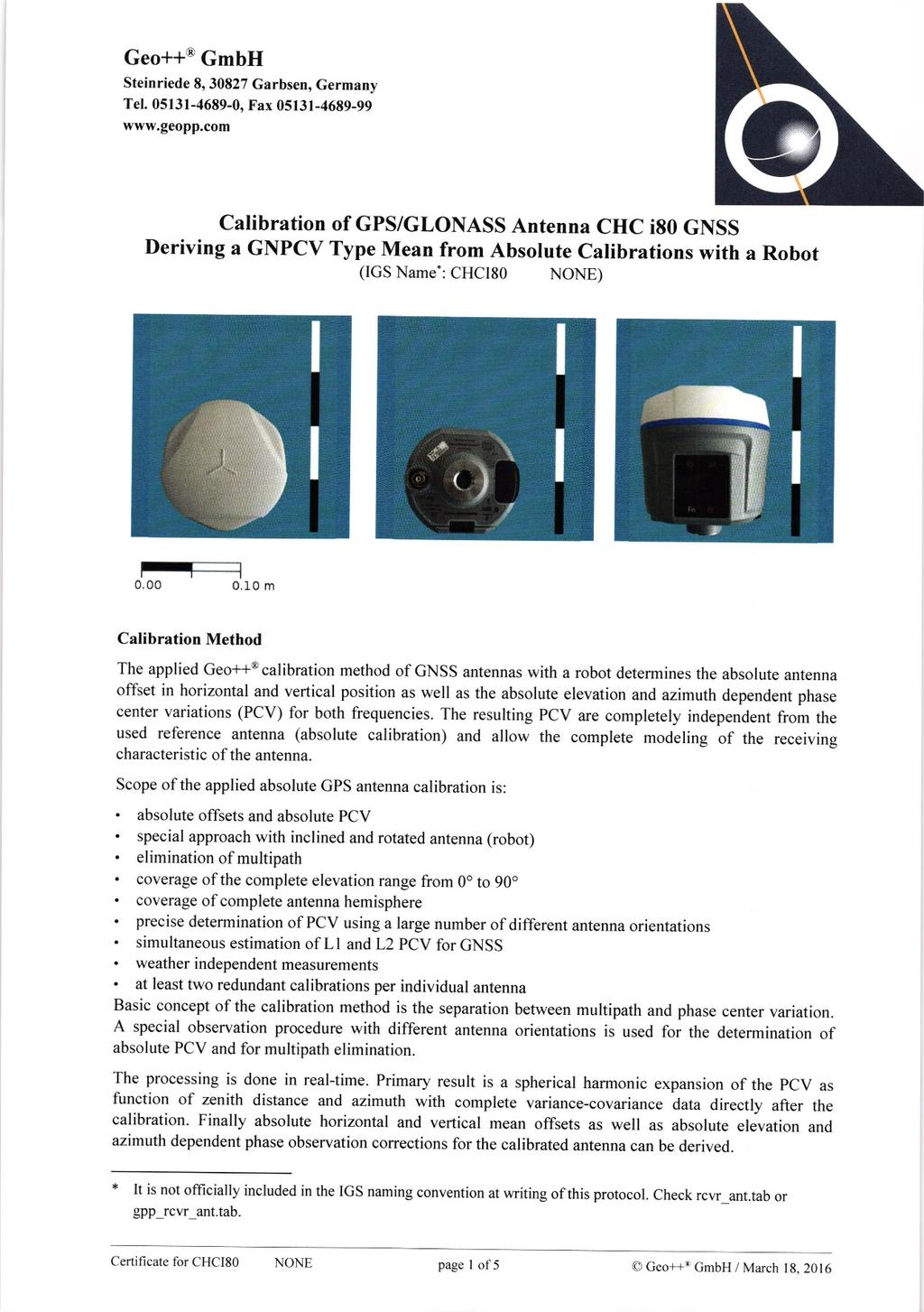
1 Absolute Antenna Calibration (Characteristics of Antenna Type) Method Geo++ GNPCV Real Time Calibration Antenna Data Manufacturer : CHC Shanghai HuaCe Navigation Technology Ltd. Antenna Type : i80 GNSS GNSS : GPS, GLO, GAL, BDS, SBAS Product Number : IGS Naming * : CHCI80 NONE Radome Data Manufacturer : Radome Type : Product Number : IGS Naming : NONE Antenna Reference Point (ARP) Horizontal Position : rotation axis, center of 5/8 thread Vertical Position : (BAM) bottom of antenna mount IGS ARP : (BAM) bottom of antenna mount North Mark Description : Man Machine Interface (MMI) points north, antenna connector points east, lemo connectors point west IGS NRP : (MMI) Man Machine Interface Remarks * It is not officially included in the IGS naming convention at writing of this protocol. Check rcvr_ant.tab or gpp_rcvr_ant.tab for acceptance. Geo++ GmbH/GeoService GmbH 1/
2 Absolute Antenna Calibration (Individual Characteristics of Antenna) Antenna Data Manufacturer : CHC Shanghai HuaCe Navigation Technology Ltd. Antenna Type : i80 GNSS GNSS : GPS, GLO, GAL, BDS, SBAS Product Number : Serial number : IGS Naming * : CHCI80 NONE Radome Data Manufacturer : Radome Type : Product Number : Serial Number : IGS Naming : NONE Calibration Characteristics GNSS System : GPS+GLONASS * Date : Number of Calibrations : 4 Setup ID : 0 Number of Frequencies : 2 Customer : CHC Shanghai HuaCe Navigation Technology Ltd. CN Shanghai Elevation Increment : 5 Azimuth Increment : 5 PCV Characteristics absolute 3D offsets absolute PCV PCV from 0 to 90 elevation elevation and azimuth dependent PCV free of any multipath influence Remarks * It is not officially included in the IGS naming convention at writing of this protocol. Check rcvr_ant.tab or gpp_rcvr_ant.tab for acceptance. * Individual GLONASS PCV were estimated using frequency independent L1, L2 GLO calibrations Geo++ GmbH/GeoService GmbH 1/
3 Absolute Antenna Calibration (Individual Characteristics of Antenna) Antenna Data Manufacturer : CHC Shanghai HuaCe Navigation Technology Ltd. Antenna Type : i80 GNSS GNSS : GPS, GLO, GAL, BDS, SBAS Product Number : Serial number : IGS Naming * : CHCI80 NONE Radome Data Manufacturer : Radome Type : Product Number : Serial Number : IGS Naming : NONE Calibration Characteristics GNSS System : GPS+GLONASS * Date : Number of Calibrations : 4 Setup ID : 0 Number of Frequencies : 2 Customer : CHC Shanghai HuaCe Navigation Technology Ltd. CN Shanghai Elevation Increment : 5 Azimuth Increment : 5 PCV Characteristics absolute 3D offsets absolute PCV PCV from 0 to 90 elevation elevation and azimuth dependent PCV free of any multipath influence Remarks * It is not officially included in the IGS naming convention at writing of this protocol. Check rcvr_ant.tab or gpp_rcvr_ant.tab for acceptance. * Individual GLONASS PCV were estimated using frequency independent L1, L2 GLO calibrations Geo++ GmbH/GeoService GmbH 1/
4 Absolute Antenna Calibration (Individual Characteristics of Antenna) Antenna Data Manufacturer : CHC Shanghai HuaCe Navigation Technology Ltd. Antenna Type : i80 GNSS GNSS : GPS, GLO, GAL, BDS, SBAS Product Number : Serial number : IGS Naming * : CHCI80 NONE Radome Data Manufacturer : Radome Type : Product Number : Serial Number : IGS Naming : NONE Calibration Characteristics GNSS System : GPS+GLONASS * Date : Number of Calibrations : 4 Setup ID : 0 Number of Frequencies : 2 Customer : CHC Shanghai HuaCe Navigation Technology Ltd. CN Shanghai Elevation Increment : 5 Azimuth Increment : 5 PCV Characteristics absolute 3D offsets absolute PCV PCV from 0 to 90 elevation elevation and azimuth dependent PCV free of any multipath influence Remarks * It is not officially included in the IGS naming convention at writing of this protocol. Check rcvr_ant.tab or gpp_rcvr_ant.tab for acceptance. * Individual GLONASS PCV were estimated using frequency independent L1, L2 GLO calibrations Geo++ GmbH/GeoService GmbH 1/
5 Absolute Antenna Calibration (Individual Characteristics of Antenna) Antenna Data Manufacturer : CHC Shanghai HuaCe Navigation Technology Ltd. Antenna Type : i80 GNSS GNSS : GPS, GLO, GAL, BDS, SBAS Product Number : Serial number : IGS Naming * : CHCI80 NONE Radome Data Manufacturer : Radome Type : Product Number : Serial Number : IGS Naming : NONE Calibration Characteristics GNSS System : GPS+GLONASS * Date : Number of Calibrations : 2 Setup ID : 0 Number of Frequencies : 2 Customer : CHC Shanghai HuaCe Navigation Technology Ltd. CN Shanghai Elevation Increment : 5 Azimuth Increment : 5 PCV Characteristics absolute 3D offsets absolute PCV PCV from 0 to 90 elevation elevation and azimuth dependent PCV free of any multipath influence Remarks * It is not officially included in the IGS naming convention at writing of this protocol. Check rcvr_ant.tab or gpp_rcvr_ant.tab for acceptance. * Individual GLONASS PCV were estimated using frequency independent L1, L2 GLO calibrations Geo++ GmbH/GeoService GmbH 1/
6 Absolute Antenna Calibration (Individual Characteristics of Antenna) Antenna Data Manufacturer : CHC Shanghai HuaCe Navigation Technology Ltd. Antenna Type : i80 GNSS GNSS : GPS, GLO, GAL, BDS, SBAS Product Number : Serial number : IGS Naming * : CHCI80 NONE Radome Data Manufacturer : Radome Type : Product Number : Serial Number : IGS Naming : NONE Calibration Characteristics GNSS System : GPS+GLONASS * Date : Number of Calibrations : 2 Setup ID : 0 Number of Frequencies : 2 Customer : CHC Shanghai HuaCe Navigation Technology Ltd. CN Shanghai Elevation Increment : 5 Azimuth Increment : 5 PCV Characteristics absolute 3D offsets absolute PCV PCV from 0 to 90 elevation elevation and azimuth dependent PCV free of any multipath influence Remarks * It is not officially included in the IGS naming convention at writing of this protocol. Check rcvr_ant.tab or gpp_rcvr_ant.tab for acceptance. * Individual GLONASS PCV were estimated using frequency independent L1, L2 GLO calibrations Geo++ GmbH/GeoService GmbH 1/
7
8
9
10
11
12 Geo++ GmbH GeoService GmbH Conditions for Antenna Calibration The Geo++ Method for Absolute Antenna Calibration operates the GNSS antenna to be calibrated on a robot and a second near by reference station. The second GNSS system consisting of an antenna (normally geodetic chokering antenna with radome) and a standard GNSS receiver is provided by Geo++ GmbH / GeoService for the period of calibration and is included in the price. Generally, standard cables, mount and GNSS receiver available at Geo++ GmbH / GeoService GmbH are used with the antenna to be calibrated. The default interfacing at the GNSS antenna is a 5/8 thread. A GNSS receiver must be made available by the customer, if the antenna cannot be operated with a standard GNSS receiver or if a particular GNSS receiver shall be used. Any special cables, cable connectors and/or mounts to be considered in the calibration must be provided by the customer. The robot used for the automated field calibration is limited with respect of antenna weight and dimensions. In case of having any doubts on the required equipment, this has to be clarified with technical staff beforehand. Absolute Antenna Calibrations require the provision of the following equipment by the customer: 1.) completely functioning GNSS antenna (to be calibrated) 2.) any documentation on GNSS antenna (geometry, definition of geometric Antenna Reference Point ARP) 3.) if applicable, antenna cable (10 meter) and/or connector to N adapter 4.) if applicable, DIN adapter or 5/8'' screw/interface for mounting antenna The antenna calibration is no verification of antenna functioning or positioning performance, because only high elevation satellites are used and the antenna is tilted and rotated. Calibrations performed with no completely functioning antennas will be charged. An appointment for the actual time period of calibrations is required and must be agreed upon with the technical staff. The period of time required for a single antenna calibration including handling and evaluation takes approximately 1 to 2 weeks. In case of several antennas within one order, handling is reduced and every additional calibration requires roughly one day. Nevertheless, due to the complexity of the system, fixed deadlines cannot be guaranteed. Please consider this for your disposition. It is absolutely necessary to contact Geo++ GmbH / GeoService GmbH before sending any antenna. The results will be delivered approx. 1 to 2 weeks after final measurements. The result of the antenna calibration is a type description, for each antenna a calibration protocol and absolute offsets as well as absolute elevation and azimuth dependent PCV in the international Antenna Exchange format ANTEX. On the antenna housing, a label will be attached showing the calibration date and, if necessary, the orientation direction used in the calibration. The calibration result has to be used for the processing of data that is observed with the calibrated antenna. It is allowed to publish the results. It is, however, proposed to advise on the loss of quality while applying the corrections for other antennas and to apply rigorous computed type means using below given guideline. The calibration data is used for the analysis of antenna model series and where appropriate used in the computation of type means of the Geo++ GNPCVDB database. A Description of the Antenna Calibration with explanations about the calibration procedure can be made available on request. The methods for antenna calibration are continuously advanced and optimised. The conditions shown above represent the state of the art at the time this text was written. Conditions for Antenna Calibration page 1 of 2 Geo++ GmbH / GeoService GmbH /
13 Geo++ GmbH GeoService GmbH Guideline text for providing the individual result of a GNSS antenna calibration: The results of the calibration are only valid for the individual antenna. The high accuracy of the absolute field calibration with a robot revealed significant individual differences in model series. Therefore, the high quality is lost while using the individual calibration for other antennas. An analysis of the antenna model series and the rigorous computation of a type mean from extensive calibration data for use with a not individually calibrated antenna is only recommended using the complete variance covariance matrix. Type means from such a computation are provided under Conditions for Antenna Calibration page 2 of 2 Geo++ GmbH / GeoService GmbH /

14 Geo++ GmbH GeoService GmbH Description of Antenna Calibration Geodetic and precise GNSS measurements make the exact knowledge of the reception characteristics of the used GNSS antennas and therefore a calibration necessary. Generally, it is differentiated between the antenna offset and the phase center variations (PCV), while the antenna offset represents a kind of mean influence of the phase center variations. The applied Geo++ calibration method determines the absolute antenna offset in horizontal and vertical position as well as absolute elevation and azimuth dependent PCV for both frequencies. The resulting PCV are completely independent from the used reference antenna and allow the complete modeling of the receiving characteristic of the antenna. This is required for a combined use of different GNSS antenna types or for differently orientated antennas. In addition, an analysis of the phase center variations and judgment of the general quality and receiving characteristics of the antenna are possible (azimuth dependency). Basic aspects of the applied absolute field calibration in real time are: absolute offsets and absolute PCV through observation configuration special approach with inclined and rotated antenna (robot) elimination of multipath coverage of the complete elevation range from 0 to 90 coverage of complete antenna hemisphere significant determination of PCV using a large number of different antenna orientations weather independent measurements simultaneous estimation of L1 and L2 PCV for GNSS at least two redundant calibrations for individual antenna Basic concept of the calibration method is a separation between multipath and phase center variation. A special observation procedure with different antenna orientations is used for the determination of absolute PCV and for multipath elimination. The processing is done in real time. Therefore the complete results are directly available after the calibration. The calibration covers the complete receiving area of the antenna down to elevation angles of 0 degree. Hence, antenna calibrated with this method are suited for All In View applications (e.g. use on reference stations). The result is stored in an absolute antenna calibration file, which contains absolute horizontal and vertical offset as well as absolute elevation and azimuth dependent corrections for the calibrated antenna. It can be arranged, that instead of elevation and azimuth dependent corrections only elevation dependent without azimuth dependency are derived. The antenna height must be measured up to the antenna reference point (ARP) of the calibration. The procedures for the antenna calibration are under steady development and progress. The presented method represents the state of the art technique at writing. Description of Antenna Calibration page 1 of 1 Geo++ GmbH / GeoService GmbH /
15 Format of Geo++ PCV Antenna File 1. NAME Geo++ antenna file 2. DESCRIPTION The following text describes the format of the Geo++ antenna files. Antenna files may contain information on the three dimensional antenna phase center offsets and antenna phase center variations (PCV). The PCV can be elevation dependent or both, elevation and azimuth dependent. 3. File Format The format of the Geo++ antenna file uses keywords to indicate different information. Comment lines are allowed and do have a '#' as the first sign of the line. However, comment lines are not allowed within a data section (i.e. the data section, which are labeled with the keyword VARIATIONS L1= and/or VARIATIONS L2=). The meaning of the keywords is described in the following. The '=' sign is part of the keyword and is not separated by a blank from the previous alphanumerical character. TYPE= is an alphanumerical description of the antenna type. The TYPE= entry generally contains the IGS naming convention consisting of Antenna code and IGS Antenna Dome code. NO OF FREQUENCIES= indicates the number of frequencies, which follow in the Geo++ antenna file. For dual frequency antenna the entry is "2", for single frequency antenna "1". OFFSETS L1= contains the L1 offsets of the phase center in north, east and height component for the L1 frequency. The unit of the values is in meter [m]. The three numbers are separated by a blank. OFFSETS L2= contains the L2 offsets of the phase center in north, east and height component for the L2 frequency. The unit of the values is in meter [m]. The three numbers are separated by a blank. ELEVATION INCREMENT= is the increment of elevation of the PCV. The unit of the increment is degree [deg]. The increment can be individually selected, however, a common value for the ELEVATION INCREMENT= is 5 deg. AZIMUTH INCREMENT= is the increment of azimuth of the PCV. The unit of the increment is degree [deg]. The increment can be individually selected, however, a common value for the AZIMUTH INCREMENT= is 5 deg. An increment of 0 specifies a file with only elevation dependent PCV. Format of Geo++ PCV Antenna File page 1 of 2 Geo++ GmbH / GeoService GmbH /
16 Format of Geo++ PCV Antenna File VARIATIONS L1= is followed in the next line by the actual PCV values of L1. The lines contain PCV values sorted by increasing elevations from 0 to 90 deg. The number of PCV values within the line is determined by "columns: 90/(elevation increment)+1". For just an elevation dependent data set, only one line of PCV correction is given. Additional azimuth dependent PCV follow in a new line. The corresponding number of lines is determined by "rows: 360/(azimuth increment)+1" and starts from 0 deg and ends with 360 deg azimuth. The row for 0 deg has to be repeated for the 360 deg row. The PCV values are given in units of meter [m]. VARIATIONS L2= is followed in the next line by the actual PCV values of L2. The lines contain PCV values sorted by increasing elevations from 0 to 90 deg. The number of PCV values within the line is determined by "columns: 90/(elevation increment)+1". For just an elevation dependent data set, only one line of PCV correction is given. Additional azimuth dependent PCV follow in a new line. The corresponding number of lines is determined by "rows: 360/(azimuth increment)+1" and starts from 0 deg and ends with 360 deg azimuth. The row for 0 deg has to be repeated for the 360 deg row. The PCV values are given in units of meter [m]. STANDARD DEVIATIONS L1= is followed in the next line by the standard deviation (1 sigma) of PCV values from the complete spherical harmonic model for the L1 frequency. The same format as for PCV is used. Refer to VARIATIONS L1=. This entry is optional. STANDARD DEVIATIONS L2= is followed in the next line by the standard deviation (1 sigma) of PCV values from the complete spherical harmonic model for the L2 frequency. The same format as for PCV is used. Refer to VARIATIONS L2=. This entry is optional. 4. DIFFERENCES to IGS/NGS FORMAT The Geo++ antenna files are different to PCV definition at IGS in the following aspects: all values given in meter (instead of mm in IGS) all parameters (offset and PCV) with the same sign convention (opposite to IGS) sign of PCV (opposite to IGS) PCV listed starting from 0 to 90 deg elevation (opposite to IGS) The Geo++ sign of the PCV originates from the intention to have consistent corrections for offset and PCV. The offsets of the phase center (PC) are added. Therefore the PCV should be added to a range or phase range as well. This defines the sign of the PCV in the Geo++ antenna file, which is opposite to the IGS. Format of Geo++ PCV Antenna File page 2 of 2 Geo++ GmbH / GeoService GmbH /
Geo++ White Paper. Comparison and Analysis of BLOCK II/IIA Offsets from Antenna Field Calibrations
 Geo++ White Paper Comparison and Analysis of BLOCK II/IIA Offsets from Antenna Field Calibrations Gerhard Wübbena, Martin Schmitz Geo++ Gesellschaft für satellitengestützte geodätische und navigatorische
RTK in Industry and Practical Work
 RTK in Industry and Practical Work Martin Schmitz Geo++ GmbH 30827 Garbsen, Germany www.geopp.de Motivation to Select a Topic Geo++ is a company with main focus on development of GNSS software and applications
Guorong Hu & Michael Moore Geodesy Section, Geoscience Australia
 Influence of using individual GPS receiver antenna calibrations on high precision geodetic positioning, case study: Northern Surat Basin Queensland 2015 GPS campaign Guorong Hu & Michael Moore Geodesy
Issues Related to the Use of Absolute GPS/GLONASS PCV Models
 Bundesamt für Landestopografie Office fédéral de topographie Ufficio federale di topografia Uffizi federal da topografia Issues Related to the Use of Absolute GPS/GLONASS PCV Models S. Schaer 1, U. Hugentobler
The importance of correct antenna calibration models for the EUREF Permanent Network
 73 The importance of correct antenna calibration models for the EUREF Permanent Network CH. VÖLKSEN 1 Abstract Station coordinates and velocities are derived today with a precision of a few millimetres.
Characterization of GOCE GPS Antennas
 Characterization of GOCE GPS Antennas Florian Dilßner, Günter Seeber (IfE), Universität Hannover, Germany Martin Schmitz, Gerhard Wübbena Geo++ GmbH, Garbsen, Germany Giovanni Toso, Damien Maeusli European
Teqc QC Results. MP1 and MP2
 T rimble T RM59900 T i-choke Ring GNSS Ant enna T est Report Article Number: 788 Rating: Unrated Last Updated: Mon, Nov 23, 2015 at 11:11 PM Location: UNAVCO facility roof NE corner Author: Henry Berglund
A New Approach for Field Calibration of Absolute Antenna Phase Center Variations
 A New Approach for Field Calibration of Absolute Antenna Phase Center Variations GERHARD WÜBBENA, MARTIN SCHMITZ Geo++, D-30827 Garbsen, Germany FALKO MENGE, GÜNTER SEEBER, CHRISTOF VÖLKSEN Institut für
CHC MINING DEFORMATION MONITORING SOLUTION
 CHC MINING DEFORMATION MONITORING SOLUTION Safety is first in mining. CHC offers solutions designed to improve safety for personnel on the ground and in the cab with 24/7 precision positioning for automatic
Titelmaster. Antenna properties
 Titelmaster On the Accuracy of Absolute GNSS Antenna Calibration in Context of Near Field Effects Barbara Görres, Philipp Zeimetz, Heiner Kuhlmann Institute of Geodesy and Geoinformation University of
supplied o-ring grease can be used to hold the o-ring in the groove during installation.
 42GOXX16A4-XT-1-1 ANTENNA GUIDE OM-20000158 Rev 1 December 2013 The 42G1215A-XT-1 is an active GPS antenna that receives the GPS L1 1575.42 MHz frequency, the GLONASS L1 1602 1626 MHz frequencies, the
Indian Institute of Technology Kanpur Department of Civil Engineering
 Indian Institute of Technology Kanpur Department of Civil Engineering Inquiry No- CE/JNM/2013-14/R-10 30 December, 2013 Subject: Quotation for supply of Integrated System/Smart System Reflectorless Robotic
Crawler Tractors PR 714 PR 764. Product information. Grade control systems
 Crawler Tractors PR 714 PR 764 Product information Grade control systems Grade Control Systems for Crawler Tractors To be successful in spite of ever-increasing time and cost pressures, construction machinery
ABSTRACT: Three types of portable units with GNSS raw data recording capability are assessed to determine static and kinematic position accuracy
 ABSTRACT: Three types of portable units with GNSS raw data recording capability are assessed to determine static and kinematic position accuracy under various environments using alternatively their internal
Simulation Analysis for Performance Improvements of GNSS-based Positioning in a Road Environment
 Simulation Analysis for Performance Improvements of GNSS-based Positioning in a Road Environment Nam-Hyeok Kim, Chi-Ho Park IT Convergence Division DGIST Daegu, S. Korea {nhkim, chpark}@dgist.ac.kr Soon
SURVEYORS BOARD OF QUEENSLAND. RTK GNSS for Cadastral Surveys. Guideline
 SURVEYORS BOARD OF QUEENSLAND RTK GNSS for Cadastral Surveys Guideline 30 November 2012 RTK GNSS for Cadastral Surveys General The Surveyors Board of Queensland has recently become aware of some issues
Geo++ GmbH Garbsen Germany
 On GNSS Station Calibration of Antenna Near-Field Effects in RTK-Networks Gerhard Wübbena, Martin Schmitz Geo++ GmbH 30827 Garbsen Germany www.geopp.com Overview Motivation Near-Field Effects / Near-Field
GPS-703-GGG and GPS-703-GGG-N
 GPS-703-GGG and GPS-703-GGG-N USER GUIDE GM-14915086 Rev 4 April 2014 The GPS-703-GGG and GPS-703-GGG-N are active antennas designed to operate at the GPS L1 frequency at 1575.42 MHz, the GPS L2 frequency
PPP with Ambiguity Resolution (AR) using RTCM-SSR
 using RTCM-SSR") PPP with Ambiguity Resolution (AR) using RTCM-SSR Gerhard Wübbena, Martin Schmitz, Andreas Bagge Geo++ GmbH 30827 Garbsen Germany www.geopp.de PPP with Ambiguity Resolution (AR) using RTCM-SSR Abstract
PPP with Ambiguity Resolution (AR) using RTCM-SSR Gerhard Wübbena, Martin Schmitz, Andreas Bagge Geo++ GmbH 30827 Garbsen Germany www.geopp.de PPP with Ambiguity Resolution (AR) using RTCM-SSR Abstract
The Impact of Different GPS Antenna Calibration Models on the EUREF Permanent Network
 103 The Impact of Different GPS Antenna Calibration Models on the EUREF Permanent Network CH. VÖLKSEN 1, F. MENGE 2 Abstract It is generally known that the phase center of a GPS antenna is not a stable
Assessing the Impact of the SCIGN Radome on Geodetic Parameter Estimates
 Assessing the Impact of the SCIGN Radome on Geodetic Parameter Estimates John J. Braun UCAR/COSMIC Program P.O. Box 3000, Boulder, CO braunj@ucar.edu 303.497.8018 Introduction The SCIGN radome is widely
Zenith Line Unconventional Use of an Automatic Total Station
 Zenith Line Unconventional Use of an Automatic Total Station Joel van Cranenbroeck, Director of Technology New Business Division, Leica Geosystems AG, Switzerland Soang Hun OH, Competence Manager Extreme
GNSS Ionosphere Analysis at CODE
 GNSS Ionosphere Analysis at CODE Stefan Schaer 2004 IGS Workshop Berne, Switzerland March 1-5 Time Series of Global Mean TEC Covering Nearly One Solar Cycle as Generated at CODE 1 Exceptionally High TEC
GPS/GNSS Antennas. В. Rama Rao W. Kunysz R. Fante К. McDonald ARTECH HOUSE. BOSTON LONDON artechhouse.com
 GPS/GNSS Antennas В. Rama Rao W. Kunysz R. Fante К. McDonald ARTECH HOUSE BOSTON LONDON artechhouse.com Contents Preface xv CHAPTER 1 Introduction to GNSS Antenna Performance Parameters 1 1.1 Role of an
A New Approach for Field Calibration of Absolute Antenna Phase Center Variations 1
 A New Approach for Field Calibration of Absolute Antenna Phase Center Variations 1 Gerhard Wübbena Geo++, Gesellschaft für satellitengestützte geodätische und navigatorische Technologien mbh Steinriede
Trimble Zephyr Geodetic 2 GNSS Antenna. Trimble GNSS-Ti Choke Ring Antenna. Trimble GNSS Choke Ring Antenna. Specifications
 Trimble GNSS GEODETIC ANTENNAS A SOLUTION FOR EVERY APPLICATION The choice is yours. Trimble provides three GNSS antennas for geodetic applications. Both solutions deliver long term performance with proven
GNSS & Coordinate Systems
 GNSS & Coordinate Systems Matthew McAdam, Marcelo Santos University of New Brunswick, Department of Geodesy and Geomatics Engineering, Fredericton, NB May 29, 2012 Santos, 2004 msantos@unb.ca 1 GNSS GNSS
GPS Technologies in PPUs Clarifying some misunderstandings. A presentation to the Latin American Forum, September Peter Selwyn Chief Executive
 GPS Technologies in PPUs Clarifying some misunderstandings A presentation to the Latin American Forum, September 2013 Peter Selwyn Chief Executive Photo courtesy of Flinders Ports Our Company Our staff:
A Solution for Every Application. Trimble GNSS Geodetic Antennas TRANSFORMING THE WAY THE WORLD WORKS
 A Solution for Every Application Trimble GNSS Geodetic Antennas TRANSFORMING THE WAY THE WORLD WORKS Trimble GNSS Geodetic Antennas Trimble geodetic antennas mitigate multipath in different ways. Each
The Role of F.I.G. in Leading the Development of International Real-Time Positioning Guidelines
 The Role of F.I.G. in Leading the Development of International Real-Time Positioning Guidelines, USA Key Words: RTN, real-time, GNSS, Guidelines SUMMARY The rapid growth of real-time reference station
Experiences in. Flight Inspecting GBAS
 Experiences in Flight Inspecting GBAS Thorsten Heinke Aerodata AG 1 Flight Inspection of GBAS Overview Basics Requirements Equipment Flight Inspection 2 Ground Based Augmentation System VDB Tx-Frequency
Fast convergence of Trimble CenterPoint RTX by regional augmentation
 Fast convergence of Trimble CenterPoint RTX by regional augmentation Dr. Ralf Drescher Trimble Terrasat GmbH, Munich EGU General Assembly 2015, Vienna Thursday, 16 April 2015 Outline Introduction CenterPoint
AUSPOS GPS Processing Report
 AUSPOS GPS Processing Report February 13, 2012 This document is a report of the GPS data processing undertaken by the AUSPOS Online GPS Processing Service (version: AUSPOS 2.02). The AUSPOS Online GPS
GPS-701-GGL and GPS-702-GGL
 GPS-701-GGL and GPS-702-GGL USER GUIDE OM-20000117 Rev 2 September 2013 The GPS-701-GGL and GPS-702-GGL are active antennas designed to receive signals from the GPS and GLONASS satellites as well as L-Band
Multi-Constellation GNSS Precise Point Positioning using GPS, GLONASS and BeiDou in Australia
 International Global Navigation Satellite Systems Society IGNSS Symposium 2015 Multi-Constellation GNSS Precise Point Positioning using GPS, GLONASS and BeiDou in Australia Xiaodong Ren 1,Suelynn Choy
GUIDELINES FOR EPN STATIONS & OPERATIONAL CENTRES
 Guidelines for EPN Stations & Operational Centres Page 1 of 16 GUIDELINES FOR EPN STATIONS & OPERATIONAL CENTRES EPN Central Bureau C. Bruyninx, epncb@oma.be Updates: Regional data centre OLG is replaced
Specifications for Post-Earthquake Precise Levelling and GNSS Survey. Version 1.0 National Geodetic Office
 Specifications for Post-Earthquake Precise Levelling and GNSS Survey Version 1.0 National Geodetic Office 24 November 2010 Specification for Post-Earthquake Precise Levelling and GNSS Survey Page 1 of
Carrier Phase Multipath Corrections Based on GNSS Signal Quality Measurements to Improve CORS Observations
 Carrier Phase Multipath Corrections Based on GNSS Signal Quality Measurements to Improve CORS Observations Christian Rost and Lambert Wanninger Geodetic Institute Technische Universität Dresden Dresden,
GNSS-750 ANTENNA GUIDE SITE SELECTION GUIDELINES. Additional Equipment Required. Accessories
 GNSS-750 ANTENNA GUIDE OM-20000120 Rev 5 October 2012 The GNSS-750 is an active antenna designed to receive signals from the GPS, Galileo and GLONASS satellites as well as L-Band signals. This antenna
DYNAMIC POSITIONING CONFERENCE October 7-8, Sensors II. Redundancy in Dynamic Positioning Systems Based on Satellite Navigation
 Return to Session Directory DYNAMIC POSITIONING CONFERENCE October 7-8, 2008 Sensors II Redundancy in Dynamic Positioning Systems Based on Satellite Navigation Ole Ørpen, Tor Egil Melgård, Arne Norum Fugro
RTCM-SSR Strategy of Bias Treatment
 RTCM-SSR Strategy of Bias Treatment Gerhard Wübbena Geo++ GmbH 30827 Garbsen Germany www.geopp.de Chair of RTCM-SSR WG www.rtcm.org RTCM-SC104 SSR Development working group established in 2007 3 message
Phase Center Calibration and Multipath Test Results of a Digital Beam-Steered Antenna Array
 Phase Center Calibration and Multipath Test Results of a Digital Beam-Steered Antenna Array Kees Stolk and Alison Brown, NAVSYS Corporation BIOGRAPHY Kees Stolk is an engineer at NAVSYS Corporation working
TEST YOUR SATELLITE NAVIGATION PERFORMANCE ON YOUR ANDROID DEVICE GLOSSARY
 TEST YOUR SATELLITE NAVIGATION PERFORMANCE ON YOUR ANDROID DEVICE GLOSSARY THE GLOSSARY This glossary aims to clarify and explain the acronyms used in GNSS and satellite navigation performance testing
GNSS CONSTRUCTION INSPECTION EQUIPMENT
 Project: Jamaica-Winhall STP 2904(1) Advertised Date: 5/30/2018 GNSS CONSTRUCTION INSPECTION EQUIPMENT DESCRIPTION. This work shall consist of furnishing, configuring, installing, maintaining, and removing
GPS-Aided INS Datasheet Rev. 2.3
 GPS-Aided INS 1 The Inertial Labs Single and Dual Antenna GPS-Aided Inertial Navigation System INS is new generation of fully-integrated, combined L1 & L2 GPS, GLONASS, GALILEO and BEIDOU navigation and
Using Frequency Diversity to Improve Measurement Speed Roger Dygert MI Technologies, 1125 Satellite Blvd., Suite 100 Suwanee, GA 30024
 Using Frequency Diversity to Improve Measurement Speed Roger Dygert MI Technologies, 1125 Satellite Blvd., Suite 1 Suwanee, GA 324 ABSTRACT Conventional antenna measurement systems use a multiplexer or
Global Navigation Satellite System for IE 5000
 Global Navigation Satellite System for IE 5000 Configuring GNSS 2 Information About GNSS 2 Guidelines and Limitations 4 Default Settings 4 Configuring GNSS 5 Configuring GNSS as Time Source for PTP 6 Verifying
GPS-Aided INS Datasheet Rev. 2.6
 GPS-Aided INS 1 GPS-Aided INS The Inertial Labs Single and Dual Antenna GPS-Aided Inertial Navigation System INS is new generation of fully-integrated, combined GPS, GLONASS, GALILEO and BEIDOU navigation
GROUND CONTROL SURVEY REPORT
 GROUND CONTROL SURVEY REPORT Services provided by: 3001, INC. a Northrop Grumman company 10300 Eaton Place Suite 340 Fairfax, VA 22030 Ground Control Survey in Support of Topographic LIDAR, RGB Imagery
GNSS Analysis with Galileo Observations in the Subnetwork of the BEK Analysis Centre
 GNSS Analysis with Galileo Observations in the Subnetwork of the BEK Analysis Centre Christof Völksen Bavarian Academy of Sciences and Humanities (BAdW) Tomasz Liwosz Warsaw University of Technology, Warsaw,
GPS Survey NAM Waddenzee
 1 of 25 Date: October 26, 2006 Author: ir. Jean-Paul Henry, 06-GPS : 1.0 Date: Author: ir. Frank Dentz, 06-GPS Checked: ir. Jean-Paul Henry, 06-GPS : 06-GPS B.V. Kubus 11 NL 3364 DG Sliedrecht Tel.: 0184
Fugro Marinestar Improvements
 Fugro Marinestar Improvements Hans Visser Fugro Intersite B.V. Improvements in Marinestar Positioning Hydro 2016 Warnemünde, 10 November 2016 Overview of presentation The Marinestar GNSS Networks The supplied
Brazil and Russia space cooperation: recent projects and future perspectives in the field of GNSS monitoring and SLR stations
 Brazil and Russia space cooperation: recent projects and future perspectives in the field of GNSS monitoring and SLR stations Renato A. Borges (UnB) and Geovany A. Borges (UnB) Emails: raborges@ene.unb.br
Prototype Software-based Receiver for Remote Sensing using Reflected GPS Signals. Dinesh Manandhar The University of Tokyo
 Prototype Software-based Receiver for Remote Sensing using Reflected GPS Signals Dinesh Manandhar The University of Tokyo dinesh@qzss.org 1 Contents Background Remote Sensing Capability System Architecture
The Impact of Performance Parameters over a DGPS Satellite Navigation System
 Australian Journal of Basic and Applied Sciences, 3(4): 4711-4719, 2009 ISSN 1991-8178 The Impact of Performance Parameters over a DGPS Satellite Navigation System 1 Madad Ali Shah, 2 Noor Ahmed Shaikh,
Field Service Procedure PCU Kit, XX97, XX97A & XX00
 1. Brief Summary: Troubleshooting document for diagnosing a fault with and replacing the PCU assembly on the XX97, XX97A and XX00 series antennas. 2. Checklist: Verify Initialization N0 Parameter Pedestal
Leica Spider Infrastructure HW Solutions Introducing: Leica GR30 & GR50
 Leica Spider Infrastructure HW Solutions Introducing: Leica GR30 & GR50 Reliable solutions for today and tomorrow Leica Spider Integrated Solutions Introducing: Leica GR30 & GR50 Outline Introducing Leica
Procedure, Field Replacement, PCU Kit, 6003A/6004, 2406 & 4003A
 1. Brief Summary: Troubleshooting document for diagnosing a fault with and replacing the PCU assembly on the 6003A/6004, 2406 & 4003A series antennas. 2. Checklist: Verify Initialization N0 Parameter Pedestal
GFZ Analysis Centre: Multi-GNSS Processing and Products
 GFZ Analysis Centre: Multi-GNSS Processing and Products Mathias Fritsche, Zhiguo Deng, Maik Uhlemann,Thomas Nischan, Markus Bradke, Markus Ramatschi, Andre Brand, Gerda Beeskow DeutschesGeoforschungsZentrum
Enhancing the Swiss Permanent GPS Network (AGNES) for GLONASS
 for GLONASS") Enhancing the Swiss Permanent GPS Network (AGNES) for GLONASS D. INEICHEN, E. BROCKMANN, S. SCHAER 1 1 Abstract Since 1998 swisstopo has been operating the Automated GPS Network of Switzerland (AGNES)
Enhancing the Swiss Permanent GPS Network (AGNES) for GLONASS D. INEICHEN, E. BROCKMANN, S. SCHAER 1 1 Abstract Since 1998 swisstopo has been operating the Automated GPS Network of Switzerland (AGNES)
Splinter Meeting of the IGS Antenna Working Group
 Splinter Meeting of the IGS Antenna Working Group Ralf Schmid Deutsches Geodätisches Forschungsinstitut der Technischen Universität München (DGFI-TUM) Munich, Germany e-mail: schmid@tum.de 1. Satellite
0526 Site Information Form (site log) International GPS Service See Instructions at: ftp://igscb.jpl.nasa.gov/pub/station/general/sitelog_instr.
 International GPS Service See Instructions at: ftp://igscb.jpl.nasa.gov/pub/station/general/sitelog_instr.") 0. Form 0526 Site Information Form (site log) International GPS Service See Instructions at: ftp://igscb.jpl.nasa.gov/pub/station/general/sitelog_instr.txt Prepared by (full name) : Schneider, Volker Date
0. Form 0526 Site Information Form (site log) International GPS Service See Instructions at: ftp://igscb.jpl.nasa.gov/pub/station/general/sitelog_instr.txt Prepared by (full name) : Schneider, Volker Date
Validation of the QuestUAV PPK System
 Validation of the QuestUAV PPK System 3cm in xy, 400ft, no GCPs, 100Ha, 25 flights Nigel King 1, Kerstin Traut 2, Cameron Weeks 3 & Ruairi Hardman 4 1 Director QuestUAV, 2 Data Analyst QuestUAV, 3 Production
670 10/26/17 SSD: 07/14/16, 09/16/17 Page 1 of 6
 SSD: 07/14/16, 09/16/17 Page 1 of 6 S P E C I A L P R O V I S I O N Section MISCELLANEOUS INCIDENTALS Item.822 - GNSS Construction Inspection Equipment Description SAMPLE PROJECT 12345 10/30/17 1.1 Work
Proposed standard for permanent GNSS reference stations in the Nordic countries
 Version 0.6 2003-05-15 Proposed standard for permanent GNSS reference stations in the Nordic countries Introduction Subproject A0 of the project Nordic Real-time Positioning Service Gunnar Hedling, Finn
RESOLUTION MSC.401(95) (Adopted on 8 June 2015) PERFORMANCE STANDARDS FOR MULTI-SYSTEM SHIPBORNE RADIONAVIGATION RECEIVERS
 (Adopted on 8 June 2015) PERFORMANCE STANDARDS FOR MULTI-SYSTEM SHIPBORNE RADIONAVIGATION RECEIVERS") ANNEX 17 MSC 95/22/Add.2 Annex 17, page 1 THE MARITIME SAFETY COMMITTEE, RECALLING Article 28(b) of the Convention on the International Maritime Organization concerning the functions of the Committee,
ANNEX 17 MSC 95/22/Add.2 Annex 17, page 1 THE MARITIME SAFETY COMMITTEE, RECALLING Article 28(b) of the Convention on the International Maritime Organization concerning the functions of the Committee,
GPS-Aided INS Datasheet Rev. 2.7
 1 The Inertial Labs Single and Dual Antenna GPS-Aided Inertial Navigation System INS is new generation of fully-integrated, combined GPS, GLONASS, GALILEO, QZSS and BEIDOU navigation and highperformance
The experimental evaluation of the EGNOS safety-of-life services for railway signalling
 Computers in Railways XII 735 The experimental evaluation of the EGNOS safety-of-life services for railway signalling A. Filip, L. Bažant & H. Mocek Railway Infrastructure Administration, LIS, Pardubice,
GNSS POST-PROCESSING SOFTWARE
 GNSS POST-PROCESSING SOFTWARE Product Overview // July 2018 EZSURV POST-PROCESSING SOFTWARE EZSurv software is designed to edit, process and analyze raw GNSS (Global Navigation Satellite System) data to
COMPARISON OF RELATIVE AND ABSOLUTE PRECISION OF OHIO S WIDE AREA GPS NETWORK INCLUDING THE COMPARISON WITH ALTERNATIVE METHODS.
 COMPARISON OF RELATIVE AND ABSOLUTE PRECISION OF OHIO S WIDE AREA GPS NETWORK INCLUDING THE COMPARISON WITH ALTERNATIVE METHODS A Thesis Presented in Partial Fulfillment of the Requirements for the Degree
Advanced Least Squares Adjustments for Post Processed GPS
 Advanced Least Squares Adjustments for Post Processed GPS 2018 Fall Conference October 18, 2018 College park, Maryland Instructor: Maser Consulting PA Independent Baselines The observations for GPS receivers
MONITORING SEA LEVEL USING GPS
 38 MONITORING SEA LEVEL USING GPS Hasanuddin Z. Abidin* Abstract GPS (Global Positioning System) is a passive, all-weather satellite-based navigation and positioning system, which is designed to provide
MISB RP 1107 RECOMMENDED PRACTICE. 24 October Metric Geopositioning Metadata Set. 1 Scope. 2 References. 2.1 Normative Reference
 MISB RP 1107 RECOMMENDED PRACTICE Metric Geopositioning Metadata Set 24 October 2013 1 Scope This Recommended Practice (RP) defines threshold and objective metadata elements for photogrammetric applications.
FieldGenius Technical Notes GPS Terminology
 FieldGenius Technical Notes GPS Terminology Almanac A set of Keplerian orbital parameters which allow the satellite positions to be predicted into the future. Ambiguity An integer value of the number of
Interface for Yaesu G-5400 and G-5600 Antenna-rotators
 Interface for Yaesu G-5400 and G-5600 Antenna-rotators I started to deal with Earth-Moon-Earth communications in the middle of 2005. I had to realize, that my two-bay DJ9BV (2.1 wavelength boom length
European Position Determination System. Technical Standards
 European Position Determination System Technical Standards Revised 2 nd Edition 24 April 2008 Resolution of the International EUPOS Steering Committee 13 th Conference, Bucharest, Romania, 23 24 April
Asian Journal of Science and Technology Vol. 08, Issue, 11, pp , November, 2017 RESEARCH ARTICLE
 Available Online at http://www.journalajst.com ASIAN JOURNAL OF SCIENCE AND TECHNOLOGY ISSN: 0976-3376 Asian Journal of Science and Technology Vol. 08, Issue, 11, pp.6697-6703, November, 2017 ARTICLE INFO
TREATMENT OF DIFFRACTION EFFECTS CAUSED BY MOUNTAIN RIDGES
 TREATMENT OF DIFFRACTION EFFECTS CAUSED BY MOUNTAIN RIDGES Rainer Klostius, Andreas Wieser, Fritz K. Brunner Institute of Engineering Geodesy and Measurement Systems, Graz University of Technology, Steyrergasse
Quick Start. Tersus GNSS Center. Configuration Tools for Tersus GNSS RTK Systems.
 Quick Start Tersus GNSS Center Configuration Tools for Tersus GNSS RTK Systems www.tersus-gnss.com July, 2016 1. Quick Start Guide of Tersus GNSS Center This quick start guide provides the basic information
4-Port Antenna Frequency Range Dual Polarization HPBW Adjust. Electr. DT
 4-Port Antenna Frequency Range Dual Polarization HPB Adjust. Electr. DT Y1 Y2 3300 3800 3300 3800 2 12 set by hand or by optional RCU (Remote Control Unit) X X 65 65 4-Port Antenna 3300 3800/3300 3800
GPS Receiver. UT-41R (DB9 and PS2 cable) Fast Acquisition Enhanced Sensitivity 12 Channel GPS Sensor Receiver. Features
 Fast Acquisition Enhanced Sensitivity 12 Channel GPS Sensor Receiver. Features") GPS Receiver Features 12 parallel channel GPS receiver 4100 simultaneous time-frequency search bins SBAS (WAAS, EGNOS) support -140dBm acquisition sensitivity -150dBm tracking sensitivity < 10 second hot
GPS Receiver Features 12 parallel channel GPS receiver 4100 simultaneous time-frequency search bins SBAS (WAAS, EGNOS) support -140dBm acquisition sensitivity -150dBm tracking sensitivity < 10 second hot
SPAN Technology System Characteristics and Performance
 SPAN Technology System Characteristics and Performance NovAtel Inc. ABSTRACT The addition of inertial technology to a GPS system provides multiple benefits, including the availability of attitude output
The added value of new GNSS to monitor the ionosphere
 The added value of new GNSS to monitor the ionosphere R. Warnant 1, C. Deprez 1, L. Van de Vyvere 2 1 University of Liege, Liege, Belgium. 2 M3 System, Wavre, Belgium. Monitoring TEC for geodetic applications
TheoDist Series FTD 05 / FTD 02. Compact Total Station
 TheoDist Series FTD 05 / FTD 02 Compact Total Station geo-fennel TheoDist Compact Total Stations The geo-fennel TheoDist Series is an instrument designed to be easy to use and quick to set up on any construction
Geodetic monitoring experiment by low-cost GNSS receivers and gogps positioning engine
 Geodetic monitoring experiment by low-cost GNSS receivers and gogps positioning engine Stefano Caldera1, Eugenio Realini1, Daisuke Yoshida2 1 2 Geomatics Research & Development (GReD) srl, c/o ComoNExT,
Ct-G551. Connectec. SiRF V GPS Module. Specifications Sheet V0.1. Features: Ct-G551 V0.1 Specification Sheet
 SiRF V GPS Module Ct-G551 Specifications Sheet V0.1 Features: SiRF StarV ultra low power chipset GPS, GLONASS, Galileo and SBAS reception for high GNSS availability and accuracy Compact module size for
GT-321R-RS232 Fast Acquisition Enhanced Sensitivity 65 Channels GPS Sensor Receiver
 GT-321R-RS232 Fast Acquisition Enhanced Sensitivity 65 Channels GPS Sensor Receiver The GT-321R-RS232 is a compact all-in-one GPS module solution intended for a broad range of Original Equipment Manufacturer
Power Requirements. Features
 Datasheet Positional accuracy (CEP50) autonomous positional error less than 2.5 meters SiRF Star IV GPS chip Satellite-based augmentation systems: WAAS, EGNOS, MSAS, GAGAN High sensitivity navigation engine
HIGH ACCURACY CROSS-POLARIZATION MEASUREMENTS USING A SINGLE REFLECTOR COMPACT RANGE
 HIGH ACCURACY CROSS-POLARIZATION MEASUREMENTS USING A SINGLE REFLECTOR COMPACT RANGE Christopher A. Rose Microwave Instrumentation Technologies 4500 River Green Parkway, Suite 200 Duluth, GA 30096 Abstract
DP5A Site Information Form (site log) DuPage County, Illinois. 0. Form
 DuPage County, Illinois. 0. Form") DP5A Site Information Form (site log) DuPage County, Illinois 0. Form Prepared by (full name) : Francine Coloma Date Prepared : 2013-04-23 Report Type : UPDATE If Update: Previous Site Log : dp5a_20090820.log
DP5A Site Information Form (site log) DuPage County, Illinois 0. Form Prepared by (full name) : Francine Coloma Date Prepared : 2013-04-23 Report Type : UPDATE If Update: Previous Site Log : dp5a_20090820.log
GPS-Aided INS Datasheet Rev. 3.0
 1 GPS-Aided INS The Inertial Labs Single and Dual Antenna GPS-Aided Inertial Navigation System INS is new generation of fully-integrated, combined GPS, GLONASS, GALILEO, QZSS, BEIDOU and L-Band navigation
STRUCTURAL BRIDGE HEALTH MONITORING WITH GLONASS AND GPS THE YEONG-JONG BRIDGE IN SOUTH KOREA
 Joël VAN CRANENBROECK Leica Geosystems AG, Switzerland, joel.vancranenbroeck@leica-geosystems.com STRUCTURAL BRIDGE HEALTH MONITORING WITH GLONASS AND GPS THE YEONG-JONG BRIDGE IN SOUTH KOREA Key words:
Lecture-1 CHAPTER 2 INTRODUCTION TO GPS
 Lecture-1 CHAPTER 2 INTRODUCTION TO GPS 2.1 History of GPS GPS is a global navigation satellite system (GNSS). It is the commonly used acronym of NAVSTAR (NAVigation System with Time And Ranging) GPS (Global
Combined Multi System GNSS Analysis for Time and Frequency Transfer
 Combined Multi System GNSS Analysis for Time and Frequency Transfer R. Dach, U. Hugentobler, T. Schildknecht, and A. Gaede rolf.dach@aiub.unibe.ch Astronomical Institute, University of Bern, Sidlerstrasse
Guide to GNSS Base stations
 Guide to GNSS Base stations Outline Introduction Example of a base station (TUMSAT) Preparation for setting up a base station Procedure for setting up a base station Examples at two other universities
Procedure, Field Replacement, PCU Kit, XX04
 1. Brief Summary: Troubleshooting document for diagnosing a fault with and replacing the XX04 series PCU assembly. 2. Checklist: Verify Initialization N0 Parameter Pedestal Error Test Motor 3. Theory of
SurvCE: configuration of S9III/S8 for a UHF radio connection
 SurvCE: configuration of S9III/S8 for a UHF radio connection This tutorial will show the basic settings of a S9III/S8 as a base, transmitting with its internal radio or with a generic external radio, and
ANALYSIS OF GPS SATELLITE OBSERVABILITY OVER THE INDIAN SOUTHERN REGION
 TJPRC: International Journal of Signal Processing Systems (TJPRC: IJSPS) Vol. 1, Issue 2, Dec 2017, 1-14 TJPRC Pvt. Ltd. ANALYSIS OF GPS SATELLITE OBSERVABILITY OVER THE INDIAN SOUTHERN REGION ANU SREE
PROCEDURE FOR GNSS EQUIPMENT VERIFICATION IN STATIC POSITIONING
 M. Tsakiri, V. Pagounis, V. Zacharis Procedure for GNSS equipment verification in static positioning PROCEDURE FOR GNSS EQUIPMENT VERIFICATION IN STATIC POSITIONING Maria TSAKIRI, School of Rural and Surveying
Shared Use of DGPS for DP and Survey Operations
 Gabriel Delgado-Saldivar The Use of DP-Assisted FPSOs for Offshore Well Testing Services DYNAMIC POSITIONING CONFERENCE October 17-18, 2006 Sensors Shared Use of DGPS for Dr. David Russell Subsea 7, Scotland