Chalmers Publication Library
|
|
|
- Linette Perry
- 5 years ago
- Views:
Transcription

1 Chalmers Publication Library Nonlinear 3-D microwave imaging for breast-cancer screening: Log, phase and logphase formulation This document has been downloaded from Chalmers Publication Library (CPL). It is the author s version of a work that was accepted for publication in: LAPC - Loughborough Antennas and Propagation Conference Citation for the published paper: Jensen, P. ; Rubaek, T. ; Mohr, J. () "Nonlinear 3-D microwave imaging for breastcancer screening: Log, phase and log-phase formulation". LAPC - Loughborough Antennas and Propagation Conference Downloaded from: Notice: Changes introduced as a result of publishing processes such as copy-editing and formatting may not be reflected in this document. For a definitive version of this work, please refer to the published source. Please note that access to the published version might require a subscription. Chalmers Publication Library (CPL) offers the possibility of retrieving research publications produced at Chalmers University of Technology. It covers all types of publications: articles, dissertations, licentiate theses, masters theses, conference papers, reports etc. Since 6 it is the official tool for Chalmers official publication statistics. To ensure that Chalmers research results are disseminated as widely as possible, an Open Access Policy has been adopted. The CPL service is administrated and maintained by Chalmers Library. (article starts on next page)
2 Nonlinear 3-D Microwave Imaging for Breast-Cancer Screening: Log, Phase and Log-Phase Formulation Peter D. Jensen, Tonny Rubæk, Johan J. Mohr and Vitaliy Zhurbenko Department of Electrical Engineering, Electromagnetic Systems, Technical University of Denmark, Ørsteds Plads, Building 3, DK- Kgs. Lyngby, Denmark. Department of Signals and Systems, Biomedical Engineering, Chalmers University of Technology, SE-96 Gothenburg, Sweden. Abstract The imaging algorithm used in the 3-D microwave imaging system for breast cancer screening, currently being developed at the Technical University of Denmark, is based on an iterative Newton-type algorithm. In this algorithm, the distribution of the electromagnetic constitutive parameters is updated in each iteration based on a comparison between the measured signals and the signals computed by a forward solver for the current parameter distribution. A key feature of the algorithm is the use of the log-phase formulation in which the measured complex signals are represented by the logarithm of their amplitudes and their unwrapped phases. In this paper, simplifications of the log-phase formulation are proposed, namely the log formulation, in which only the logarithm of the amplitudes are used, and the phase formulation, in which only the unwrapped phases are used. These formulations allow for the use of simpler tomographic systems in which only the amplitudes or the phases of the signals are measured. The performance of the algorithms using the two proposed formulations is investigated by reconstructing images of data collected with the above-mentioned imaging system, and the resulting images are compared with those obtained using the log-phase formulation. I. INTRODUCTION Microwave imaging for breast-cancer screening has attracted the attention of an increasing number of research groups during the last decade, and is seen as a possible supplement to the widely used X-ray mammography. Today s trend in microwave imaging for breast-cancer detection goes towards 3-D measurement setups to avoid the inherent errors stemming from applying -D algorithms to what indeed is a 3-D problem []. Two different approaches are currently being pursued for microwave imaging of the breast: One is the ultrawideband radar-based approach, in which the images are constructed by determining the pointof-origin of reflected pulses; the other is the tomographic or inverse-scattering approach in which the images are created by solving an inverse-scattering problem based on Maxwell s equations. This approach results in a reconstruction of the distribution of the constitutive electromagnetic properties, i.e., permittivity and conductivity, of the breast. The prototype system, currently being developed at the Technical University of Denmark (DTU), belongs to the latter group. It is a 3-D imaging system that uses an iterative Newton-type algorithm for solving the inverse problem. In this algorithm, the distribution of electromagnetic constitutive parameters is updated in each iteration based on a comparison between the measured signals and the signals computed by a forward solver for the current parameter distribution. It has earlier been shown that the so-called log-phase formulation, in which the measured signals are represented by the logarithm of their amplitudes and their unwrapped phases, significantly improves the performance of the reconstruction algorithm compared to the complex formulation []. In this paper, simplifications of the log-phase formulation are proposed. These simplified formulations consist of two different algorithms using only the amplitude or only the phase, respectively, of the signals. The use of such formulations would enable the use of simpler tomographic systems that measure only either the amplitude or the phase of the signals at the terminals of the antennas. For an amplitude-only system, the measurements are simplified since there is no longer need for coherent measurements. This also allows for a complete decoupling between the transmitting and receiving units, since the individual transmitter and receiver units no longer need to have a common feed to their local oscillators (LO). This, in turn, can eliminate signals leaking from the transmitter through the common LO channels to the receiver. A problem which can seriously affect the performance of tomographic systems in which signal levels more than db below the transmitted signal are often observed on the receiving channels [3]. In a phase-only measurement system, on the other hand, the requirements to the AD converter in the system can be relaxed and so can the requirements to the overall dynamic performance, which is most often needed in these systems to handle the large changes in amplitudes, observed by the receiving antennas depending on their relative position to the transmitting antenna. Hence, it is of great interest to investigate whether or not satisfactory results can be obtained using either amplitude-only or phase-only measurements, thereby relaxing the requirements
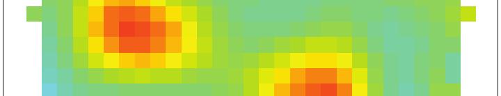
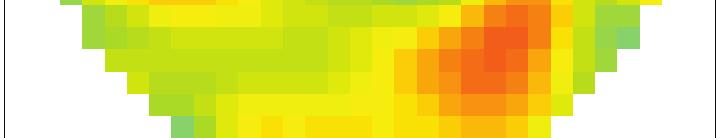
3 to the hardware of the tomography system. II. IMAGING SYSTEM The DTU system is designed to be operated at a single frequency in the range from 3 MHz to 3GHz. The system consists of 3 monopole antennas submerged in a glycerinwater coupling liquid. Each of the antennas are equipped with its own transceiver module. The antennas are positioned in a cylindrical setup with rows. Each row consists of antennas equally spaced by on a circle with radius cm. The distance between the rows is. cm, and the individual rows are rotated. with respect to the rows above and below [3]. The antenna system is positioned in a cylindrical tank with a radius of cm. The lossy coupling liquid assures that reflections from the side, bottom and top of tank are attenuated so the influence of reflections becomes negligible. During a measurement sequence, each antenna in turn transmits while the response is measured on the 3 other antennas, yielding 99 measurement of the amplitude and phase. Due to reciprocity the measurements are pairwise redundant. III. IMAGING ALGORITHM The distribution of electromagnetic constitutive parameters in the imaging domain can be represented by the squared complex wave number. Using the time notation e jωt, the squared complex wave number in the domain is given by k (r) =ω μ ɛ(r) jωμ σ(r), () where r is the position vector, ω is the angular frequency, μ is the free-space permeability, ɛ is the permittivity, and σ is the conductivity. The domain is discretized into N cells cubic cells, and the constitutive parameters are assumed to be constant within each cell. Then, it holds that k (r) =k l for r V l, () where V l is the volume covered by cell number l =,,..., N cells. The distribution of the squared complex wave numbers in the imaging domain is determined by solving the nonlinear minimization problem, given by k =argmin{ S meas S calc (k ) } =argmin{ S res (k ) } subj. to regularization (3) using an iterative Newton algorithm. In this expression, the N cells -element vector k holds the distribution of real and imaginary parts of the squared complex wave numbers k l. The vectors S calc (k ) and S meas holds the calculated signals for a given distribution of the squared wave numbers and the measured signals, respectively. S res is the residual vector. Since the problem is both under determined and ill-posed, regularization must be applied when solving the problem. In this paper, the Newton algorithm outlined in [] is applied for solving the inversion problem. And the regularization is obtained by solving for the update problem with a limited number of iterations (here 6) in the CGLS algorithm, corresponding to applying over-regularization [, Sec. 6.3]. IV. LOG, PHASE AND LOG-PHASE FORMULATION It has earlier been shown that the log-phase formulation has advantages compared to the complex formulation []. The complex and log-phase formulations differ in how the data is represented in the vectors S meas and S calc (k ).In both formulations, each combination of transmitting antenna t and receiving antenna r gives two elements in each of the vectors S meas and S calc (k ). In the complex formulation, the elements are given by and R I =Re{St,r obj St,r empty} () =Im{St,r obj St,r empty}, () where obj and St,r empty denotes measurements with and without an object present in the imaging system, respectively. In the log-phase formulation, the vectors are based on the logarithm of the signals log =log S t,r + j, (6) wherein is the unwrapped phase of the signal. The N meas elements of the vectors S meas and S calc may now be determined as S log =log t,r obj log empty (7) and phase = obj empty. () In the log formulation proposed in this paper, it is assumed that only the amplitudes of the signals are given. The elements in the vectors S meas and S calc (k ) are then determined using (7) and the number of elements in the vectors is half of the corresponding number when using the log-phase formulation, i.e., N meas. Similarly, in the proposed phase formulation, it is assumed that only the phases of the signals are given. The elements in the vectors S meas and S calc (k ) are thus determined using () and the number of elements in each of the vectors is N meas. In this paper, the phase-only and amplitude-only data sets are created from a measurement containing both amplitude and phase but the data sets could instead be obtained from systems which only measure one or the other. V. RESULTS AND DISCUSSION To illustrate the performance of the proposed log and phase algorithms compared with that of the log-phase algorithm, the results from the three imaging setups shown in Fig. will be discussed. Configuration and consist of thin plastic spheres with a diameter of cm that are filled with tap water and positioned in the coupling liquid of the imaging system. The centers of the spheres are placed in the xyplane with z = cm, i.e., aligned with the third row of antennas, counting from the top. For configuration, the center of the sphere is located at (x, y) = (.,.7) cm. In configuration, the spheres form a equilateral triangle with a side length of 6 cm, with the sphere in the top-right corner


.")


, with a slightly lower maximum permittivity of r.")
 is dominated by artifacts and the sphere is not clearly defined. Fig.")


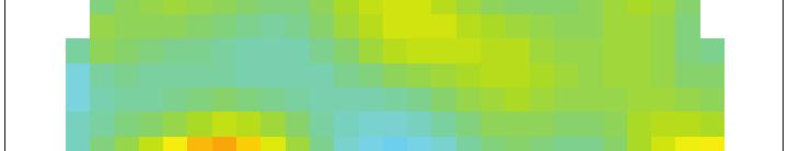
4 (a) Configuration. (b) Configuration. (c) Configuration 3. Fig.. Water filled plastic spheres submerged in coupling liquid. Results for configuration, and 3 are presented in Fig., Fig. 3 and Fig., respectively. r. σ σ r. r being at the same position as the sphere in configuration. Each floating sphere is held in place with a piece of thread fixed to the bottom of the tank. Configuration 3, shown in Fig. (c) consists of two plastic spheres with a diameter of cm that are filled with tap water. These are less ideal test objects than the larger spheres used in the first two configurations because more volume is taken up by the plastic (the spheres are approximately mm thick, implying that only 73% of the total volume is water). The spheres are positioned with their centers at the same positions as the two upper spheres in configuration. The used imaging domain is cylindrically shaped with a diameter of cm and a height of. cm with the top positioned at z = cm. It is divided into cubic cells with a side length of. cm. Fig. shows images of the reconstructed relative permittivity and conductivity for configuration at GHz. The images are slices in the xy-plane at z =. cm. The relative permittivity of tap water and the coupling liquid is approximately and, respectively. The conductivity values are approximately. S/m for tap water and.7 S/m for the coupling liquid. Figs. (a) and (b) show log-phase formulation results. The sphere stands out clearly in the image of the permittivity. It is circularly shaped and it is positioned as expected. The reconstructed relative permittivity has a maximum of r. As expected, the conductivity of the object is lower than the surrounding liquid in the image, but the sphere is not as clearly defined as in the permittivity image and artifacts can be seen around the sphere. Overall, though, the images obtained using log-phase formulation are in good agreement with the actual values. Figs. (c) and (d) show log formulation results. Fig. (c) looks very similar to Fig. (a), with a slightly lower maximum permittivity of r. As with the log-phase formulation, the reconstructed conductivity in Fig. (d) is dominated by artifacts and the sphere is not clearly defined. Fig.(e) and (f) show phase formulation results. Again, the image of the permittivity is good, and the sphere is clearly defined, but with an slightly lower maximum value of r. As with the two previous examples, the sphere is not clearly defined in the conductivity image in Fig. (f). Fig. 3 shows the reconstructed images for configuration using the different formulations. Again, the spheres clearly. σ Fig.. Configuration : Images of the reconstructed relative permittivity, r = /, and conductivity, σ, in the xy-plane at z =. cm, at GHz, after Newton iterations using the three different formulations. The black circles indicate the actual position. stand out in the permittivity images. The maximum values of the reconstructed permittivity for the log-phase, log and phase formulation are 63, and 3, respectively. The image of the permittivity obtained using phase formulation looks notably smeared compared to the other two permittivity images. As was the case with configuration, the spheres are not well defined in the conductivity images which are dominated by artifacts. Fig. shows the reconstruction of configuration 3 that consist of smaller spheres. The reconstructions are done at the frequency GHz. At this frequency, the relative permittivity is approximately for tap water and 7. for the coupling liquid. The corresponding values for the conductivity is approximately. S/m and. S/m. The small spheres clearly stand out in the permittivity images. The small spheres are also seen in the conductivity images using log-phase and phase formulation. The spheres are not visible in the conductivity image obtained with the log formulation. In addition to the examples shown here, a number of other


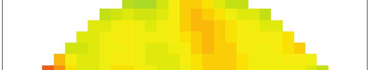
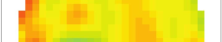
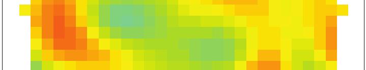


5 σ σ.. σ Fig. 3. Configuration : Images of the reconstructed relative permittivity, = ɛ/ɛ, and conductivity, σ, inthexy-plane at z =. cm, at GHz, after Newton iterations using the three different formulations. The black circles indicate the actual position.. σ σ.. σ Fig.. Configuration 3: Images of the reconstructed relative permittivity, = ɛ/ɛ, and conductivity, σ, in the xy-plane at z =. cm, at GHz, after Newton iterations using the three different formulations. The black circles indicate the actual position. imaging experiments have been carried out. These all show similar results to the examples shown here, i.e., that the phase formulation yields results that are comparable to those of the log-phase formulation, while the log formulation yields slightly worse results. Especially for the conductivity images. VI. CONCLUSION Two simplifications of the log-phase formulation have been proposed, one being the log formulation in which only the amplitude measurements are used, the other being the phase formulation in which only the phase measurements are used. The formulations have been tested with data collected with a 3-D microwave imaging system, and the images compared with those obtained using the log-phase formulation. The results show that a simplified imaging system, either measuring the amplitude or the phase of the signals, gives satisfactory results that are in many cases comparable to the results obtained with a full measurements of both amplitude and phase. However, the phase-only system seems to yield better images compared to the amplitude-only system. VII. ACKNOWLEDGMENTS The work presented in this paper is, in part, funded by the Villum Kann Rasmussen Foundation. REFERENCES [] P. Meaney, K. Paulsen, S. Geimer, S. Haider, and M. Fanning, Quantification of 3-d field effects during -d microwave imaging, IEEE Transaction on Biomedical Engineering, vol. 9, no. 7, pp. 7 7, Jan. [] P. Meaney, K. Paulsen, B. Pogue, and M. Miga, Microwave image reconstruction utilizing log-magnitude and unwrapped phase to improve high-contrast object recovery, IEEE Transactions on Medical Imaging, vol., no., pp. 6,. [3] V. Zhurbenko, T. Rubæk, V. Krozer, and P. Meincke, Design and realisation of a microwave three-dimensional imaging system with application to breast-cancer detection, IET Microwaves, Antennas & Propagation, vol., no., pp.,. [] T. Rubæk, O. Kim, and P. Meincke, Computational validation of a 3-d microwave imaging system for breast-cancer screening, IEEE Transactions on Antennas and Propagation, vol. 7, no. 7, pp., 9. [] P. C. Hansen, Rank-Deficient and Discrete Ill-Posed Problems: Numerical Aspects of Linear Inversion, ser. Monographs on Mathematical Modeling and Computation. SIAM, 99.
Bayesian Estimation of Tumours in Breasts Using Microwave Imaging
 Bayesian Estimation of Tumours in Breasts Using Microwave Imaging Aleksandar Jeremic 1, Elham Khosrowshahli 2 1 Department of Electrical & Computer Engineering McMaster University, Hamilton, ON, Canada
Computational Validation of a 3-D Microwave Imaging System for Breast-Cancer Screening
 Downloaded from orbit.dtu.dk on: Sep 30, 2018 Computational Validation of a 3-D Microwave Imaging System for Breast-Cancer Screening Rubæk, Tonny; Kim, Oleksiy S.; Meincke, Peter Published in: I E E E
A modified Bow-Tie Antenna for Microwave Imaging Applications
 Journal of Microwaves, Optoelectronics and Electromagnetic Applications, Vol. 7, No. 2, December 2008 115 A modified Bow-Tie Antenna for Microwave Imaging Applications Elizabeth Rufus, Zachariah C Alex,
Microwave Imaging of Biological Tissues: the current status in the research area
 Microwave Imaging of Biological Tissues: the current status in the research area Tommy Gunnarsson December 18, 2006 Department of Computer Science and Electronics, Mälardalen University Abstract Microwave
Monoconical RF Antenna
 Page 1 of 8 RF and Microwave Models : Monoconical RF Antenna Monoconical RF Antenna Introduction Conical antennas are useful for many applications due to their broadband characteristics and relative simplicity.
The Effect of the Head Size on the Ear-to-Ear Radio-Propagation Channel for Body- Centric Wireless Networks
 Downloaded from orbit.dtu.dk on: Jan 25, 2019 The Effect of the Head Size on the Ear-to-Ear Radio-Propagation Channel for Body- Centric Wireless Networks Kvist, Søren Helstrup; Thaysen, Jesper; Jakobsen,
Accurate Antenna Models in Ground Penetrating Radar Diffraction Tomography
 Downloaded from orbit.dtu.dk on: Oct 04, 2018 Accurate Antenna Models in Ground Penetrating Radar Diffraction Tomography Meincke, Peter; Kim, Oleksiy S. Published in: Proceedings of IEEE Antennas and Propagation
SCATTERING POLARIMETRY PART 1. Dr. A. Bhattacharya (Slide courtesy Prof. E. Pottier and Prof. L. Ferro-Famil)
") SCATTERING POLARIMETRY PART 1 Dr. A. Bhattacharya (Slide courtesy Prof. E. Pottier and Prof. L. Ferro-Famil) 2 That s how it looks! Wave Polarisation An electromagnetic (EM) plane wave has time-varying
SCATTERING POLARIMETRY PART 1 Dr. A. Bhattacharya (Slide courtesy Prof. E. Pottier and Prof. L. Ferro-Famil) 2 That s how it looks! Wave Polarisation An electromagnetic (EM) plane wave has time-varying
Log-periodic dipole antenna with low cross-polarization
 Downloaded from orbit.dtu.dk on: Feb 13, 2018 Log-periodic dipole antenna with low cross-polarization Pivnenko, Sergey Published in: Proceedings of the European Conference on Antennas and Propagation Link
Full Polarimetric THz Imaging System in Comparison with Infrared Thermography
 11th European Conference on Non-Destructive Testing (ECNDT 2014), October 6-10, 2014, Prague, Czech Republic More Info at Open Access Database www.ndt.net/?id=16556 Full Polarimetric THz Imaging System
Chalmers Publication Library
 Chalmers Publication Library State-of-the-art measurements of LTE terminal antenna performance using reverberation chamber This document has been downloaded from Chalmers Publication Library (CPL). It
Performance Analysis of Different Ultra Wideband Planar Monopole Antennas as EMI sensors
 International Journal of Electronics and Communication Engineering. ISSN 09742166 Volume 5, Number 4 (2012), pp. 435445 International Research Publication House http://www.irphouse.com Performance Analysis
300 GHz Imaging System with 8 Meter Stand-off Distance and One-Dimensional Synthetic Image Reconstruction for Remote Detection of Material Defects
 Downloaded from orbit.dtu.dk on: Jan 02, 2019 300 GHz Imaging System with 8 Meter Stand-off Distance and One-Dimensional Synthetic Image Reconstruction for Remote Detection of Material Defects Keil, Andreas;
Research Article Medical Applications of Microwave Imaging
 Hindawi Publishing Corporation e Scientific World Journal Volume, Article ID, pages http://dx.doi.org/.// Research Article Medical Applications of Microwave Imaging Zhao Wang, Eng Gee Lim, Yujun Tang,
Department of Technology and Built Environment
 Department of Technology and Built Environment Design of Ultra Wideband Antenna Array for Microwave Tomography Master s Thesis in Electronics/Telecommunication Laeeq Riaz January, 2011 Supervisor: Ms.
A compressive sensing approach for enhancing breast cancer detection using a hybrid DBT / NRI configuration
 1 A compressive sensing approach for enhancing breast cancer detection using a hybrid DBT / NRI configuration Richard Obermeier and Jose Angel Martinez-Lorenzo arxiv:1603.06151v1 [math.oc] 19 Mar 2016
Compact microstrip bandpass filter with tunable notch
 Downloaded from orbit.dtu.dk on: Feb 16, 2018 Compact microstrip bandpass filter with tunable notch Christensen, Silas; Zhurbenko, Vitaliy; Johansen, Tom Keinicke Published in: Proceedings of 2014 20th
Simulation Measurement for Detection of the Breast Tumors by Using Ultra-Wideband Radar-Based Microwave Technique
 Simulation Measurement for Detection of the Breast Tumors by Using Ultra-Wideband Radar-Based Microwave Technique Ali Recai Celik 1 1Doctor, Dicle University Electrical and Electronics Engineering Department,
Microwave Image Reconstruction Utilizing Log-Magnitude and Unwrapped Phase to Improve High-Contrast Object Recovery
 104 IEEE TRANSACTIONS ON MEDICAL IMAGING, VOL. 20, NO. 2, FEBRUARY 2001 Microwave Image Reconstruction Utilizing Log-Magnitude and Unwrapped Phase to Improve High-Contrast Object Recovery Paul M. Meaney*,
UWB SHORT RANGE IMAGING
 ICONIC 2007 St. Louis, MO, USA June 27-29, 2007 UWB SHORT RANGE IMAGING A. Papió, J.M. Jornet, P. Ceballos, J. Romeu, S. Blanch, A. Cardama, L. Jofre Department of Signal Theory and Communications (TSC)
Design of UWB Monopole Antenna for Oil Pipeline Imaging
 Progress In Electromagnetics Research C, Vol. 69, 8, 26 Design of UWB Monopole Antenna for Oil Pipeline Imaging Richa Chandel,AnilK.Gautam, *, and Binod K. Kanaujia 2 Abstract A novel miniaturized design
Design and Measurement of a 2.45 Ghz On-Body Antenna Optimized for Hearing Instrument Applications
 Downloaded from orbit.dtu.dk on: Dec 20, 2017 Design and of a 2.45 Ghz On-Body Antenna Optimized for Hearing Instrument Applications Kvist, Søren Helstrup; Jakobsen, Kaj Bjarne; Thaysen, Jesper Published
Chalmers Publication Library
 Chalmers Publication Library About Random LOS in Rician Fading Channels for MIMO OTA Tests This document has been downloaded from Chalmers Publication Library (CPL). It is the author s version of a work
Chalmers Publication Library
 Chalmers Publication Library Investigation of Transitions for Use in Inverted Microstrip Gap Waveguide Antenna Arrays This document has been downloaded from Chalmers Publication Library (CPL). It is the
CONTRIBUTIONS to microwave tomography have been
 IEEE TRANSACTIONS ON ANTENNAS AND PROPAGATION, VOL. 59, NO. 5, MAY 2011 1597 A Novel Microwave Tomography System Using a Rotatable Conductive Enclosure Puyan Mojabi, Member, IEEE, and Joe LoVetri, Senior
Wideband Loaded Wire Bow-tie Antenna for Near Field Imaging Using Genetic Algorithms
 PIERS ONLINE, VOL. 4, NO. 5, 2008 591 Wideband Loaded Wire Bow-tie Antenna for Near Field Imaging Using Genetic Algorithms S. W. J. Chung, R. A. Abd-Alhameed, C. H. See, and P. S. Excell Mobile and Satellite
King Fahad University of Petroleum and Minerals Electrical Engineering EE 407. Course Project Triangular Microstrip Antenna
 King Fahad University of Petroleum and Minerals Electrical Engineering EE 407 Course Project Triangular Microstrip Antenna Done By 1. Mustafa Al-Ramadhan 236141 2. Saad Al Huwaimal 235903 3. Ghurmallah
MICROWAVE IMAGING TECHNIQUE USING UWB SIGNAL FOR BREAST CANCER DETECTION
 MICROWAVE IMAGING TECHNIQUE USING UWB SIGNAL FOR BREAST CANCER DETECTION Siti Hasmah binti Mohd Salleh, Mohd Azlishah Othman, Nadhirah Ali, Hamzah Asyrani Sulaiman, Mohamad Harris Misran and Mohamad Zoinol
SUPPLEMENTARY INFORMATION
 A full-parameter unidirectional metamaterial cloak for microwaves Bilinear Transformations Figure 1 Graphical depiction of the bilinear transformation and derived material parameters. (a) The transformation
DESIGN AND ANALYSIS OF RECTANGULAR MICROSTRIP PATCH ANTENNA USING METAMATERIAL FOR BETTER EFFICIENCY
 DESIGN AND ANALYSIS OF RECTANGULAR MICROSTRIP PATCH ANTENNA USING METAMATERIAL FOR BETTER EFFICIENCY Gourav Singh Rajput, Department of Electronics, Madhav Institute of Technology and Science Gwalior,
Conformal Microwave Tomography using a Broadband Non-Contacting Monopole Antenna Array
 Conformal Microwave Tomography using a Broadband Non-Contacting Monopole Antenna Array Epstein NR, Golnabi AG, Meaney PM, Paulsen KD Thayer School of Engineering Dartmouth College Hanover NH, USA neil.r.epstein@dartmouth.edu
Chalmers Publication Library
 Chalmers Publication Library Several new ultra-wideband antenna systems for radio telescopes and industry sensor imaging process This document has been downloaded from Chalmers Publication Library (CPL).
Groundwave Propagation, Part One
 Groundwave Propagation, Part One 1 Planar Earth groundwave 2 Planar Earth groundwave example 3 Planar Earth elevated antenna effects Levis, Johnson, Teixeira (ESL/OSU) Radiowave Propagation August 17,
Chalmers Publication Library
 Chalmers Publication Library Over-the-air performance testing of wireless terminals by data throughput measurements in reverberation chamber This document has been downloaded from Chalmers Publication
FDTD Antenna Modeling for Ultrawideband. Electromagnetic Remote Sensing
 FDTD Antenna Modeling for Ultrawideband Electromagnetic Remote Sensing A Thesis Presented in Partial Fulfillment of the requirements for the Distinction Project in the College of Engineering at The Ohio
Advanced Architectures for Self- Interference Cancellation in Full-Duplex Radios: Algorithms and Measurements
 Advanced Architectures for Self- Interference Cancellation in Full-Duplex Radios: Algorithms and Measurements Dani Korpi, Mona AghababaeeTafreshi, Mauno Piililä, Lauri Anttila, Mikko Valkama Department
Effect of Antennae Polarization Relative to Tunnel Orientation on Electromagnetic Wave Scattering due to Underground Tunnels
 Presented at the COMSOL Conference 2009 Boston Effect of Antennae Polarization Relative to Tunnel Orientation on Electromagnetic Wave Scattering due to Underground Tunnels Arvin Farid Assistant Professor
Millimeter-Wave Holographic Imaging Algorithm with Amplitude Corrections
 Progress In Electromagnetics Research M, Vol. 49, 33 39, 2016 Millimeter-Wave Holographic Imaging Algorithm with Amplitude Corrections Yu-Kun Zhu 1, 2, *, Ming-Hui Yang 1,LiangWu 1, Yun Sun 1, and Xiao-Wei
Towards new vistas in preamplifier design for MRI
 Downloaded from orbit.dtu.dk on: Sep 18, 218 Towards new vistas in preamplifier design for MRI Johansen, Daniel Højrup; Sanchez, Juan Diego; Zhurbenko, Vitaliy; Ardenkjær-Larsen, Jan Henrik Published in:
Laitinen, Tommi. Published in: IEEE Transactions on Antennas and Propagation. Link to article, DOI: /TAP Publication date: 2008
 Downloaded from orbit.dtu.dk on: Feb 04, 2018 Double phi-step theta-scanning Technique for Spherical Near-Field Antenna Measurements Double -Step -Scanning Technique for Spherical Near-Field Antenna Measurements
Imaging System for Non-Destructive Testing of Glass Fibre Reinforced Plastics Martin NEZADAL 1,2, Jan SCHÜR 1, Lorenz-Peter SCHMIDT 1
 5th International Symposium on NDT in Aerospace, 13-15th November 2013, Singapore Imaging System for Non-Destructive Testing of Glass Fibre Reinforced Plastics Martin NEZADAL 1,2, Jan SCHÜR 1, Lorenz-Peter
Non Invasive Electromagnetic Quality Control System
 ECNDT 2006 - Tu.4.6.2 Non Invasive Electromagnetic Quality Control System Jérôme DREAN, Luc DUCHESNE, SATIMO, Courtaboeuf, France Per NOREN, SATIMO, Gothenburg (Sweden) Abstract. The quality control of
A Fan-Shaped Circularly Polarized Patch Antenna for UMTS Band
 Progress In Electromagnetics Research C, Vol. 52, 101 107, 2014 A Fan-Shaped Circularly Polarized Patch Antenna for UMTS Band Sumitha Mathew, Ramachandran Anitha, Thazhe K. Roshna, Chakkanattu M. Nijas,
Projects in microwave theory 2017
 Electrical and information technology Projects in microwave theory 2017 Write a short report on the project that includes a short abstract, an introduction, a theory section, a section on the results and
Dual Feed Microstrip Patch Antenna for Wlan Applications
 IOSR Journal of Electronics and Communication Engineering (IOSR-JECE) e-issn: 2278-2834,p- ISSN: 2278-8735.Volume 10, Issue 5, Ver. I (Sep - Oct.2015), PP 01-05 www.iosrjournals.org Dual Feed Microstrip
Neural Blind Separation for Electromagnetic Source Localization and Assessment
 Neural Blind Separation for Electromagnetic Source Localization and Assessment L. Albini, P. Burrascano, E. Cardelli, A. Faba, S. Fiori Department of Industrial Engineering, University of Perugia Via G.
GAIN COMPARISON MEASUREMENTS IN SPHERICAL NEAR-FIELD SCANNING
 GAIN COMPARISON MEASUREMENTS IN SPHERICAL NEAR-FIELD SCANNING ABSTRACT by Doren W. Hess and John R. Jones Scientific-Atlanta, Inc. A set of near-field measurements has been performed by combining the methods
Parameter Estimation Techniques for Ultrasound Phase Reconstruction. Fatemeh Vakhshiteh Sept. 16, 2010
 Parameter Estimation Techniques for Ultrasound Phase Reconstruction Fatemeh Vakhshiteh Sept. 16, 2010 Presentation Outline Motivation Thesis Objectives Background Simulation Quadrature Phase Measurement
Human Brain Microwave Imaging Signal Processing: Frequency Domain (S-parameters) to Time Domain Conversion
 to Time Domain Conversion") Engineering,, 5, -6 doi:.46/eng..55b7 Published Online May (http://www.scirp.org/journal/eng) Human Brain Microwave Imaging Signal Processing: Frequency Domain (S-parameters) to Time Domain Conversion
Engineering,, 5, -6 doi:.46/eng..55b7 Published Online May (http://www.scirp.org/journal/eng) Human Brain Microwave Imaging Signal Processing: Frequency Domain (S-parameters) to Time Domain Conversion
THE ELECTROMAGNETIC FIELD THEORY. Dr. A. Bhattacharya
 1 THE ELECTROMAGNETIC FIELD THEORY Dr. A. Bhattacharya The Underlying EM Fields The development of radar as an imaging modality has been based on power and power density It is important to understand some
SHIELDING EFFECTIVENESS
 SHIELDING Electronic devices are commonly packaged in a conducting enclosure (shield) in order to (1) prevent the electronic devices inside the shield from radiating emissions efficiently and/or (2) prevent
H. Arab 1, C. Akyel 2
 angle VIRTUAL TRANSMISSION LINE OF CONICAL TYPE COAXIALOPEN-ENDED PROBE FOR DIELECTRIC MEASUREMENT H. Arab 1, C. Akyel 2 ABSTRACT 1,2 Ecole Polytechnique of Montreal, Canada An improved virtually conical
Analysis of Crack Detection in Metallic and Non-metallic Surfaces Using FDTD Method
 ECNDT 26 - We.4.3.2 Analysis of Crack Detection in Metallic and Non-metallic Surfaces Using FDTD Method Faezeh Sh.A.GHASEMI 1,2, M. S. ABRISHAMIAN 1, A. MOVAFEGHI 2 1 K. N. Toosi University of Technology,
Chalmers Publication Library
 Chalmers Publication Library Arrangements and Applications of Self-grounded Antennas This document has been downloaded from Chalmers Publication Library (CPL). It is the author s version of a work that
Microwave Cancer Therapy
 Page 1 of 9 RF and Microwave Models : Microwave Cancer Therapy Microwave Cancer Therapy Electromagnetic heating appears in a wide range of engineering problems and is ideally suited for modeling in COMSOL
Chalmers Publication Library
 Chalmers Publication Library Parabolic cylindrical reflector antenna at 6 Hz with line feed in gap waveguide technology This document has been downloaded from Chalmers Publication Library (CPL). It is
Chapter 2 Analysis of RF Interferometer
 Chapter 2 Analysis of RF Interferometer In this chapter, the principle of RF interferometry is investigated for the measurement of the permittivity and thickness of dielectric as shown in Figs..2,.3, and.4
L-BAND COPLANAR SLOT LOOP ANTENNA FOR INET APPLICATIONS
 L-BAND COPLANAR SLOT LOOP ANTENNA FOR INET APPLICATIONS Jeyasingh Nithianandam Electrical and Computer Engineering Department Morgan State University, 500 Perring Parkway, Baltimore, Maryland 5 ABSTRACT
EC ANTENNA AND WAVE PROPAGATION
 EC6602 - ANTENNA AND WAVE PROPAGATION FUNDAMENTALS PART-B QUESTION BANK UNIT 1 1. Define the following parameters w.r.t antenna: i. Radiation resistance. ii. Beam area. iii. Radiation intensity. iv. Directivity.
COUPLED SECTORIAL LOOP ANTENNA (CSLA) FOR ULTRA-WIDEBAND APPLICATIONS *
 FOR ULTRA-WIDEBAND APPLICATIONS *") COUPLED SECTORIAL LOOP ANTENNA (CSLA) FOR ULTRA-WIDEBAND APPLICATIONS * Nader Behdad, and Kamal Sarabandi Department of Electrical Engineering and Computer Science University of Michigan, Ann Arbor, MI,
COUPLED SECTORIAL LOOP ANTENNA (CSLA) FOR ULTRA-WIDEBAND APPLICATIONS * Nader Behdad, and Kamal Sarabandi Department of Electrical Engineering and Computer Science University of Michigan, Ann Arbor, MI,
Detection of Multipath Propagation Effects in SAR-Tomography with MIMO Modes
 Detection of Multipath Propagation Effects in SAR-Tomography with MIMO Modes Tobias Rommel, German Aerospace Centre (DLR), tobias.rommel@dlr.de, Germany Gerhard Krieger, German Aerospace Centre (DLR),
Challenges in the Design of Microwave Imaging Systems for Breast Cancer Detection
 Downloaded from orbit.dtu.dk on: Sep 19, 218 Challenges in the Design of Microwave Imaging Systems for Breast Cancer Detection Zhurbenko, Vitaliy Published in: Advances in Electrical and Computer Engineering
Ultra-Wideband Coplanar-Fed Monopoles: A Comparative Study
 RADIOENGINEERING, VOL. 17, NO. 1, APRIL 2007 37 Ultra-Wideband Coplanar-Fed Monopoles: A Comparative Study Jana JILKOVÁ, Zbyněk RAIDA Dept. of Radio Electronics, Brno University of Technology, Purkyňova
Γ L = Γ S =
 TOPIC: Microwave Circuits Q.1 Determine the S parameters of two port network consisting of a series resistance R terminated at its input and output ports by the characteristic impedance Zo. Q.2 Input matching
Extraction of Antenna Gain from Path Loss Model. for In-Body Communication
 Extraction of Antenna Gain from Path Loss Model for In-Body Communication Divya Kurup, Wout Joseph, Emmeric Tanghe, Günter Vermeeren, Luc Martens Ghent University / IBBT, Dept. of Information Technology
Chapter 4 The RF Link
 Chapter 4 The RF Link The fundamental elements of the communications satellite Radio Frequency (RF) or free space link are introduced. Basic transmission parameters, such as Antenna gain, Beamwidth, Free-space
A Novel Method for Determining the Lower Bound of Antenna Efficiency
 A Novel Method for Determining the Lower Bound of Antenna Efficiency Jason B. Coder #1, John M. Ladbury 2, Mark Golkowski #3 # Department of Electrical Engineering, University of Colorado Denver 1201 5th
Chalmers Publication Library
 Chalmers Publication Library On S-Parameter based Complex Correlation of Multi- Port Antenna This document has been downloaded from Chalmers Publication Library (CPL). It is the author s version of a work
II. MODELING SPECIFICATIONS
 The 18th Annual IEEE International Symposium on Personal, Indoor and Mobile Radio Communications (PIMRC'07) EFFECT OF METAL DOOR ON INDOOR RADIO CHANNEL Jinwon Choi, Noh-Gyoung Kang, Jong-Min Ra, Jun-Sung
Estimation of speed, average received power and received signal in wireless systems using wavelets
 Estimation of speed, average received power and received signal in wireless systems using wavelets Rajat Bansal Sumit Laad Group Members rajat@ee.iitb.ac.in laad@ee.iitb.ac.in 01D07010 01D07011 Abstract
TOPIC 2 WAVEGUIDE AND COMPONENTS
 TOPIC 2 WAVEGUIDE AND COMPONENTS COURSE LEARNING OUTCOME (CLO) CLO1 Explain clearly the generation of microwave, the effects of microwave radiation and the propagation of electromagnetic in a waveguide
Compressive Through-focus Imaging
 PIERS ONLINE, VOL. 6, NO. 8, 788 Compressive Through-focus Imaging Oren Mangoubi and Edwin A. Marengo Yale University, USA Northeastern University, USA Abstract Optical sensing and imaging applications
EMC ANALYSIS OF ANTENNAS MOUNTED ON ELECTRICALLY LARGE PLATFORMS WITH PARALLEL FDTD METHOD
 Progress In Electromagnetics Research, PIER 84, 205 220, 2008 EMC ANALYSIS OF ANTENNAS MOUNTED ON ELECTRICALLY LARGE PLATFORMS WITH PARALLEL FDTD METHOD J.-Z. Lei, C.-H. Liang, W. Ding, and Y. Zhang National
Digitally-Controlled RF Self- Interference Canceller for Full-Duplex Radios
 Digitally-Controlled RF Self- nterference Canceller for Full-Duplex Radios Joose Tamminen 1, Matias Turunen 1, Dani Korpi 1, Timo Huusari 2, Yang-Seok Choi 2, Shilpa Talwar 2, and Mikko Valkama 1 1 Dept.
ELECTROMAGNETIC WAVES PIERC 03. Progress In Electromagnetics Research C
 ELECTROMAGNETIC WAVES PIERC 03 Progress In Electromagnetics Research C c 2008 EMW Publishing. All rights reserved. No part of this publication may be reproduced. Request for permission should be addressed
Chalmers Publication Library
 Chalmers Publication Library A Quadraxial Feed for Ultra-Wide Bandwidth Quadruple-Ridged Flared Horn Antennas This document has been downloaded from Chalmers Publication Library (CPL). It is the author
A HIGH-POWER LOW-LOSS MULTIPORT RADIAL WAVEGUIDE POWER DIVIDER
 Progress In Electromagnetics Research Letters, Vol. 31, 189 198, 2012 A HIGH-POWER LOW-LOSS MULTIPORT RADIAL WAVEGUIDE POWER DIVIDER X.-Q. Li *, Q.-X. Liu, and J.-Q. Zhang School of Physical Science and
TRANSMIT AND RECEIVE DIVERSITY IN BODY-CENTRIC WIRELESS COMMUNICATIONS
 TRANSMIT AND RECEIVE DIVERSITY IN BODY-CENTRIC WIRELESS COMMUNICATIONS Pablo F. Medina, Søren H. Kvist, Kaj B. Jakobsen s111942@student.dtu.dk, shk@elektro.dtu.dk, kbj@elektro.dtu.dk Department of Electrical
Plane-Wave Characterization of Antennas Close to a Planar Interface
 Downloaded from orbit.dtu.dk on: Sep 15, 2018 Plane-Wave Characterization of Antennas Close to a Planar Interface Meincke, Peter; Hansen, Thorkild Published in: I E E E Transactions on Geoscience and Remote
Coherently enhanced wireless power transfer: theory and experiment
 Journal of Physics: Conference Series PAPER OPEN ACCESS Coherently enhanced wireless power transfer: theory and experiment To cite this article: S. Li et al 2018 J. Phys.: Conf. Ser. 1092 012078 View the
Adaptive f-xy Hankel matrix rank reduction filter to attenuate coherent noise Nirupama (Pam) Nagarajappa*, CGGVeritas
 Nagarajappa*, CGGVeritas") Adaptive f-xy Hankel matrix rank reduction filter to attenuate coherent noise Nirupama (Pam) Nagarajappa*, CGGVeritas Summary The reliability of seismic attribute estimation depends on reliable signal.
Adaptive f-xy Hankel matrix rank reduction filter to attenuate coherent noise Nirupama (Pam) Nagarajappa*, CGGVeritas Summary The reliability of seismic attribute estimation depends on reliable signal.
ECE 476/ECE 501C/CS Wireless Communication Systems Winter Lecture 6: Fading
 ECE 476/ECE 501C/CS 513 - Wireless Communication Systems Winter 2003 Lecture 6: Fading Last lecture: Large scale propagation properties of wireless systems - slowly varying properties that depend primarily
Design of Circular Monopole Antenna for Ultra Wide Band Application
 Design of Circular Monopole Antenna for Ultra Wide Band Application Dristi Mistry 1, Falguni Raval 2 1 MTECH(C.S.E.) V. T. Patel Department of E. &. C. Engineering, Charotar University of Science and Technology,
1 Diffraction of Microwaves
 1 Diffraction of Microwaves 1.1 Purpose In this lab you will investigate the coherent scattering of electromagnetic waves from a periodic structure. The experiment is a direct analog of the Bragg diffraction
Broadband array antennas using a self-complementary antenna array and dielectric slabs
 Broadband array antennas using a self-complementary antenna array and dielectric slabs Gustafsson, Mats Published: 24-- Link to publication Citation for published version (APA): Gustafsson, M. (24). Broadband
Chalmers Publication Library
 Chalmers Publication Library Design of 6GHz Planar Array Antennas Using PCB-based Microstrip-Ridge Gap Waveguide and SIW This document has been downloaded from Chalmers Publication Library (CPL). It is
WIRELESS power transfer through coupled antennas
 3442 IEEE TRANSACTIONS ON ANTENNAS AND PROPAGATION, VOL. 58, NO. 11, NOVEMBER 2010 Fundamental Aspects of Near-Field Coupling Small Antennas for Wireless Power Transfer Jaechun Lee, Member, IEEE, and Sangwook
ECE 476/ECE 501C/CS Wireless Communication Systems Winter Lecture 6: Fading
 ECE 476/ECE 501C/CS 513 - Wireless Communication Systems Winter 2004 Lecture 6: Fading Last lecture: Large scale propagation properties of wireless systems - slowly varying properties that depend primarily
Description of TEAM Workshop Problem 29: Whole body cavity resonator
 Description of TEAM Workshop Problem 29: Whole body cavity resonator Yasushi Kanai Department of Information and Electronics Engineering, Niigata Institute of Technology, Kashiwazaki 945-1195, JAPAN Tel:
RF AND MICROWAVE ENGINEERING
 RF AND MICROWAVE ENGINEERING FUNDAMENTALS OF WIRELESS COMMUNICATIONS Frank Gustrau Dortmund University of Applied Sciences and Arts, Germany WILEY A John Wiley & Sons, Ltd., Publication Preface List of
Investigation of negative sequence injection capability in H-bridge Multilevel STATCOM
 Investigation of negative sequence injection capability in H-bridge Multilevel STATCOM Ehsan Behrouzian 1, Massimo Bongiorno 1, Hector Zelaya De La Parra 1,2 1 CHALMERS UNIVERSITY OF TECHNOLOGY SE-412
Frequency Response Calculations of Input Characteristics of Cavity-Backed Aperture Antennas Using AWE With Hybrid FEM/MoM Technique
 NASA Contractor Report 4764 Frequency Response Calculations of Input Characteristics of Cavity-Backed Aperture Antennas Using AWE With Hybrid FEM/MoM Technique C. J. Reddy Hampton University Hampton, Virginia
Single-turn and multi-turn coil domains in 3D COMSOL. All rights reserved.
 Single-turn and multi-turn coil domains in 3D 2012 COMSOL. All rights reserved. Introduction This tutorial shows how to use the Single-Turn Coil Domain and Multi-Turn Coil Domain features in COMSOL s Magnetic
Chalmers Publication Library
 Chalmers Publication Library Efficiency, Correlation, and Diversity Gain of UWB Multiport elf-grounded Bow- Tie Antenna in Rich Isotropic Multipath Environment This document has been downloaded from Chalmers
Study on the frequency-dependent scattering characteristic of human body for a fast UWB radar imaging algorithm
 EMT-6-9 UWB *, ( ) Study on the frequency-dependent scattering characteristic of human body for a fast UWB radar imaging algorithm Takuya Sakamoto and Toru Sato (Kyoto University) Abstract The UWB pulse
Analysing Radio Wave Propagation Model for Indoor Wireless Communication
 Analysing Radio Wave Propagation Model for Indoor Wireless Communication Phyo Thu Zar Tun, Aye Su Hlaing Abstract for several wireless communication technologies, many propagation models have been presented
Dual-slot feeding technique for broadband Fabry- Perot cavity antennas Konstantinidis, Konstantinos; Feresidis, Alexandros; Hall, Peter
 Dual-slot feeding technique for broadband Fabry- Perot cavity antennas Konstantinidis, Konstantinos; Feresidis, Alexandros; Hall, Peter DOI: 1.149/iet-map.214.53 Document Version Peer reviewed version
Practical Considerations for Radiated Immunities Measurement using ETS-Lindgren EMC Probes
 Practical Considerations for Radiated Immunities Measurement using ETS-Lindgren EMC Probes Detectors/Modulated Field ETS-Lindgren EMC probes (HI-6022/6122, HI-6005/6105, and HI-6053/6153) use diode detectors
Chalmers Publication Library
 Chalmers Publication Library Equivalent Circuit of a Quadraxial Feed for Ultra-Wide Bandwidth Quadruple- Ridged Flared Horn Antennas This document has been downloaded from Chalmers Publication Library
Development of a Wireless Communications Planning Tool for Optimizing Indoor Coverage Areas
 Development of a Wireless Communications Planning Tool for Optimizing Indoor Coverage Areas A. Dimitriou, T. Vasiliadis, G. Sergiadis Aristotle University of Thessaloniki, School of Engineering, Dept.