ISSUE 18 Jun, Hytera Customer Service Express
|
|
|
- Myles Flynn
- 5 years ago
- Views:
Transcription


1 ISSUE 18 Jun, Hytera Customer Service Express

2 CONTENTS 02 Hytera Training Introduction 05 TC-508 Can t Power on Fault Repair Case 08 TC518 Can't Power On Fault Repair Case 12 TC-610 No TX Voice Repair Case 14 TC-780 Power-on Malfunction Repair Case 16 The Difference Between Busy, Waiting and Queuing In Tetra 18 How to fix the error band issue on TC Ignition Sense on Tetra Mobiles 22 PD78X and MD78X Repeater Wake Up Failed Error Cause Analysis 1

3 Hytera Training Introduction 2
4 Hytera Curriculum system Wireless solution Product technology Engineering technology The applied technical training for Hytera product extension and integration (including product principle, function, program design, case studies, device selection, etc.) The applied technical training for Hytera single product (including principle, functions, technical specifications, hardware / software components, installanation, setting, commissioning, repair and maintenance, etc.) The applied technical training for wireless communications products delivery in engineering (including surveying, measuring, construction practices, network planning and optimization, product integration device selection, etc.) Wireless Solution Product Technology Training Course Duration Training Course Duration IP multi-site application technical training (A,P,E) 9 H Tetra terminal application technical training 12 H Digital Smartdispatch system application technical training (A,P) 9 H Tetra terminal repairing technical training (A,P) DMR terminal application technical training 18 H 12 H Repeater coverage application technical training 9 H DMR terminal repairing technical training(a,p) 18 H Video surveillance and emergency dispatch system technical training Engineering Technology 6 H Analog terminal application technical training Analog terminal repairing technical training (A,P) 12 H 18 H Engineering specifications and operational training 9 H Tetra trunking system technical training 30 H Engineering electrical measurement application technical training(a,p) 9 H DMR trunking system technical training Analog trunking system technical training (P) 30 H 30 H Network planning and design application technical training(a,p) 9 H Digital simulcast technical training (A,P) DMR trunking system Lite technical training 15 H 30 H 3
5 Digital SmartDispatch System Application Technical Training (P) Benefits of Training: Hytera SmartDispatch product,function application and common networking type. IP multi-site connect application solution design and common network troubleshooting. Digital SmartDispatch system case study. Installation,configuration,debuging and troubleshooting of digital SmartDispatch system. Targeted participants: Technical suppport engineer, service engineer; Admission Requirements: Got digital SmartDispatch system application technology certification A. Understand IP protocol and network knowledge. Performance of IP network equipment. Class Hour: 3 days(theroy & Operation & Discussion & Case study) Class Size: 4-8 persons DMR trunking System Technical Training (P) Benefits of Training: DMR standard and technology advantage. Hytera DMR trunking system and function. Function,installation,configuration and commissioning of DMR trunking system single station(including hardware/software) Installation and application of NMS/DMS/RMS from DMR trunking system single station. DMR trunking system database backup. The method of DMR trunking single station troubleshooting. Function and programming of DMR trunking terminal Targeted participants: Technical support engineer, service engineer. Admission Requirements: Got DMR trunking system technology certification A. Understand Linux system and operation commands. IP network basic knowledge. Class Hour: 5 days (Theroy & Operation & Discussion & Case study) Class Size: 4-8 persons Engineering Technology--Engineering Specifications and Operation Benefits of Training: The basic skill of system installation. Engineering installation specifications. Operation of engineering safety. Case analysis of engineering construction. Targeted participants: Service engineer, technical support engineer. Admission Requirements: Know well the principle of wireless communication. More than 1 year engineering construction experience. Class Hour: 1.5 days(theroy & Operation & Case study) Class Size: 5-15 persons 4
6 TC-508 Can t Power on Fault Repair Case 1. Fault Phenomenon Description a. Connect to direct-current power supply and turn on the radio, no power on voice. Press the side key, no response either. b. Connect to direct-current power supply and turn on the radio, there is power on voice but the radio turns off immediately. It can t power on normally. 2. Fault Reason Analysis a. According to above phenomenon, the terminal can t power on. b. The cause of can t power on: power supply circuit problem, CPU control circuit problem, reset circuit problem. 3. Specific maintenance case Case 1 Model Frequency Firmware Version TC MHZ V Fault Phenomenon Description TC-508 has no power on voice, no response; press the side key, no response either. Fault Reason Analysis From the fault description, the fault is can t power on. It is caused by power supply/cpu control circuit/cpu crystal clock fault. Detection Steps a. Supply 7.4V power to the main board. Use a multimeter to test the two pins voltage of the volume switch. The two pins voltage of the volume switch is 7.4V. It is normal. b. Test the voltage of the CPU power supply pin, it is 3V. It is normal. c. Test the voltage of pin#1 and pin#4 of CPU clock crystal, they are 1.3V, we preliminarily judge that the power on crystal works abnormally so that it can t provide reference clock. Normally, in the oscillation period, the voltage should be different between pin#1 and pin#4. d. Replace the crystal, test the voltage of pin#1 and pin#4. Pin#1 is 1.3V, pin#4 is 0.7V. The radio can power on normally. The problem is solved. 5
7 CPU Supply Power:3V Normally it is 1.3V Normally it is Conclusion The problem is that the CPU clock crystal can t oscillate when powering on the radio. Normally, the oscillation could only happen when the voltage is different between pin#1 and pin#4. Case 2 Model Frequency Firmware version TC MHZ V Fault Phenomenon Turn on the radio, there is power on voice but the radio turns off immediately. It can t power on normally. Fault Analysis From the above fault analysis, the fault should be automatically power off after power on. The problem should be caused by control circuit problem or battery voltage test circuit problem. Detection Steps a. First check the contact between the battery and the battery connector. b. Take out the mainboard, we found the main radio has been watered slightly. The components around CPU are corroded and turned to be black. c. We can judge that the battery low voltage test circuit error cause the battery die. Use a multimeter to test the R602 battery power supply voltage is 7.4V. No voltage at the other side. The multimeter resistor test shows the circuit is open. Take off the resistor, we find the copper has been corroded. d. Clean PCB board and replace R602. Test the voltage, it is 3V. (In the full battery condition, if the battery power supply is low, the voltage should be low as well.) e. After replacing the resistor, the radio can be powered on normally and are not turned off automatically. The problem is solved. 6

8 When the power supply is 7.4V, the voltage should be 3V at this, Power Supply Voltage:7.4V The Resistor s Location in PCB Conclusion The cause is battery low voltage test circuit problem, but we mistook that the automatical turn -off is caused by exhausted battery. 7
9 TC518 Can t Power On Fault Repair Case 1. Faulty Phenomenon Description There is no reaction when connecting to the 7.4V standard power. 2. Faulty Reason Analysis 1) The fault is can t power on according to the above phenomenon; 2) Detection place for hardware circuit: power supply circuit, CPU control circuit, main related components are power up key S601,L601,U601, CPU power supply IC U603,reset IC U605,memory U606 and CPU time crystal oscillator; 3) The main cause of software is E2ROM data missing, CPU program error, solutions are CPU/E2ROM replacement or E2ROM rewriting; 4) Power supply circuit diagram is shown as below: Power supply circuit principle: 7.4V DC power converts to a stable 5V DC power through U601. One supplies 4.5DC voltage to TX, RX and VCO circuit after converting through U602. The other one supplies 3V to MCU, E2ROM and PLL after converting through U603. Special case: there is another similar faulty situation whose repair method is different, that is, the radio is in empty channel, the speaker and indicator damages at the same time(very low rate). 3. Specific Maintenance Case Case 1 Radio Type Frequency Firmware Version TC MHz V
10 Faulty Phenomenon Description There is no powering up volume, flashing indicator, current and no reaction after pressing PTT. Faulty Reason Analysis This fault is can t power on according to the fault phenomenon. We have to check power supply circuit and CPU control circuit. Test Steps(See figure 1 and 2) 1) There is no liquid corrosive, burned trace of components after disassembling the radio; 2) Power on the radio, and use multimeter to test L601 s two ports. It is 7.4V which is normal; 3) Test S601 powering up key s upper volt, it is 7.4V, it will change to 0V after pressing the PTT key, which is normal; 4) Test U601 s output voltage after pressing powering up key, it is 5V which is normal; 5) Test IC U603 s supplying voltage to MCU and E2ROM, it is 3V which is normal; 6) Test supplying voltage pin to CPU, it is 3V; Test the 8 th pin of U606 of E2ROM, it is 3V, all of them are normal; 7) Use the oscillograph to detect time crystal oscillator X601 to see whether it can oscillate, and then test the two pins, there is no oscillation sine wave output, it is abnormal. Replace a new X601 and power on the radio, and the fault disappears; L601Voltage:7.4V Powering up key U601output:5V U603output: 3V Figure 1 9
11 CPU time crystal oscillator X601 Figure 2 Summary This fault is the damaged time crystal oscillator X601 of CPU makes CPU out of work. Case 2 Radio Type Frequency Firmware Version TC MHz V Faulty Phenomenon description There is no powering up volume, flashing indicator, current and no respondence after pressing PTT. Faulty reason analysis This fault is can t power on according to the fault phenomenon, we have to check power supply circuit and CPU control circuit. Test steps(see figure 1 and 2) 1) There is no liquid corrosive, burned trace of components after disassembling the radio; 2) After powering on the radio, use multimeter to test L601 s two ports, it is 7.4V which is normal; 3) Test S601 powering up key s upper volt, it is 7.4V, it will change to 0V after pressing the PTT key, which is normal; 4) Test U601 s output voltage after pressing powering up key, it is 5V which is normal; 5) Use multimeter to test the 2 nd pin input voltage of U603, it is 5V which is normal, test the 6 th pin output voltage, it is 0V which is abnormal. We can conclude that the front circuit part of U603 is normal which means the cause is the back part of U603 or itself. Remove inductance L603 and break the latter circuit and then power on the radio to test the 6 th pin of U603, it is still 0V and U603 may damage, and replace U603 and power on the radio to test again, it is still 0V and the radio still can t power on. 6) Use anti-static nipper to touch several components around U603 slightly and find that one filter C608 is broken which is short circuit after testing by multimeter. The radio returns to normal condition after replacing C608 and soldering L603 back. 10
12 U601 output: 5V U603output: 3V Inductance L603 Figure 3 Faulty component C608 Summary This fault is the broken C608 causes 0V output of U603 which leads the can t power on fault, in order to improve the repair efficiency, it is better to break the inductance like L603 or similar on the main circuit to narrow the fault detection range when checking the power supply circuit. 11
13 TC-610 No TX Voice Repair Case 1. Failure Phenomenon Description 1) Press TC-610 PTT button to setup a call to radio A, TC-610 red LED glows and radio A green LED glows as well. But there is no voice output on radio A. 2) Check the TX FM deviation by test machine, there is no FM deviation. 2. Failure Causse Analysis 1) According to the above failure phenomenon and check result, we can judge that the radio has TX voice problem. 2) To analyze this problem in the view of hardware part, the involved circuits are: MIC, MIC accessory input circuit, TX audio processing circuit, or VCO modulation circuit. The possible damaged components are: MIC, MIC protection diode, MIC accessory interface, or audio processing IC (AN29160AA). 3. Specific Repair Case Case one Model Frequency Firmware Version TC MHz V Phenomenon Description Press TC-610 radio PTT button to setup a call to another radio A, TC-610 red LED glows and radio A green LED glows as well. But there is no voice output on radio A. Check it and find there is no TX FM deviation. Failure Analysis Based on the failure phenomenon, we can judge that it s no TX voice problem. There is no FM deviation, so no voice signal is transmitted. Check Steps 1) Measure the pin #1 of MIC, the value is 4.5V and it s no problem. 2) Check and find that the pin #2 and #4 of MIC Jack are connected, it s no problem. (If pin #2 and #4 are not connected, it means the MIC Jack is damaged.) 3) Connect the TC-610 to the integrated test instrument by test cable. Find the TX Test item of integrated test instrument and set the audio output as: 1 KHz, 100mv. And then press the 12
14 PTT to make radio in transmitting mode. Check the TX power value and the other TX related parameters, they are all OK but still no FM deviation. Generally there should be 4 KHz FM deviation. 4) Set the test environment just like step 3. Press the PTT and measure the pin #2 signal of MIC Jack by oscilloscope, the value is 0mV. If the signal is normal, there should be 100mV. 5) Use the multimeter to measure the resistance to ground value of pin #2 of MIC Jack, the value is 0Ω and it s abnormal. It tells that the pin #2 of MIC Jack is grounding short-circuit. It is possible that the MIC Jack is damaged. 6) Replace the MIC Jack, the problem still exists. Re-measure the resistance to ground value of pin #2 of MIC Jack, the value is still 0Ω. 7) Dismantle the protection diode D200 and measure the resistance value, the positive and negative resistance are both 0Ω, it means that the diode is damaged. 8) Replace the D200, and then check TX FM deviation, the value is OK. TX function is also working well. This problem is solved. D200 Diode MIC output signal to audio processing IC AN29160AA MIC MIC JACK Summary This problem is caused by the damaged diode D200. The function of D200 is to protect the accessory interface circuit from being damaged by foreign high voltage signal. If D200 is damaged, it could cause the FM deviation problem and no TX voice problem. 13
15 TC-780 Power-on Malfunction Repair Case Failure Phenomenon Description Phenomenon: Connect the battery or DC power supply (7.4V) to the TC-780 then power on the radio, there is not any response: No display by LCD, no speaker voice, no LED flashing or glowing. 1. Failure Reason Analysis According to the above failure phenomenon and the below check result, we can judge that the radio can t be switched on. The involved circuits are: power supply circuit, and CPU circuit. The main related components are: volume switch, MHz crystal oscillator, U602, and U Specific Repair Case Case one Model Frequency Firmware Version TC MHz V Phenomenon Description Power on the radio, there is not any response: no power-on sound, or no display by LCD. Press the PTT, there is no response and reading and writing are out of work. Failure Analysis This is power-on malfunction according to the phenomenon. We have to check power supply circuit and CPU control circuit. Check Steps 3. Power on the radio, and measure the voltage of two ports of F601, both of them are 7.4V. They are normal. 4. Measure the output voltage of power switch SW601. it s 7.4V which is normal. 5. Measure the voltage of M5V (supply voltage to CPU), there is no 5V output. Measure the pin #3 and pin #1 of U602, there is 7.4V voltage input to pin#3 but there is no 5V output from pin #1. It is abnormal. The U602 is probably damaged. 6. Replace U602 and check M5V output. It s 5V which is normal. And the radio can be switched on normally. The problem is solved. 14
16 7.4V U602 Voltage-stabilized IC M5V Summary This power-on malfunction is caused by damaged U602, and the U602 is the voltage-stabilized IC. 15
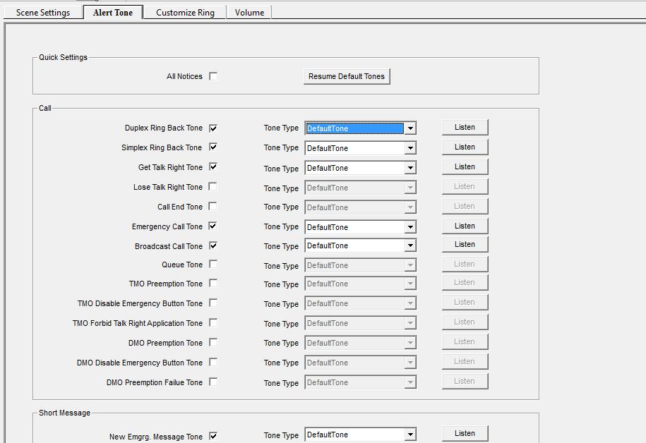
17 The Difference Between Busy, Waiting and Queuing In Tetra 1. Background In the Tetra radio, when the channel, group or radio are busy, there will be some alert: Busy, Waiting and Queuing if a second person wants to request a call. What s the difference among them? Do they have alert tone? 2. Difference 1) What situation will cause Busy? We take the individual call for example. There are 3 radios, Radio1, Radio2 and Radio3. Radio 1 is talking to Radio2. At the same time, if Radio3 requests a call to Radio2, Radio3 will show "the RX radio is busy" alert tip on the screen, and there will be an alert tone telling you that Radio2 is busy. 2) What situation will cause Queuing? In several communications condition (using different base station channel), for example, there are 3 base station channels, and 3 communications are already using the 3 base station channels. The base station channel resources are full, if the 4th or 5th communications need to use the base station channel resource, they need to "Queuing", and there will be queue alert tone. 3) What situation will cause Waiting? In one talking group, if one radio is talking, the other radios will receive the voice from the TX radio. In this condition, if any other radios in that group want to talk, they need to wait. When the other radio press PTT, there will be "Waiting" alert tip on the screen, but no alert tone, because the radio is already in use, and it cannot make the other invoice. Actually if you receive the TX radio, you can hear the voice from the TX radio, you can easily tell that someone is using the group for talking. You have to wait, no need of alert tone. 3. Alert Tone Setting In Tetra Terminal Go to Tetra CPS->User Settings->Voice->Alert Tone, you can set the alert tone: 16
18 17
 450-520mhz.")

19 How to fix the error band issue on TC700 Problem: TC700 U(7) mhz get corrupted with the U(8) mhz. Radio information: a), TC 700U(7) 2tone b), Frequency: Mhz c), S/N: 09924A0534 1, This is the label on the back: 2, The out of range windows appear and remind you to modify the test frequencies 18


20 Solution: here is one suggested method for you to solve the problem as below: 1, We need disassemble the radio first. 2, Then connect the SELF(see below picture) to ground, at same time press Top key then power up the radio, the radio will enter reset mode. 3, Check your CPS model type, if the ninth is the correct band, switch the Channel Selector Knob to ninth (corresponding number), and press PTT. Resetting will be OK. 19
, Software: Tetra mobile Ignition sense feature had been added in version 4.0.")
21 Ignition Sense on Tetra Mobiles 1. Purpose This document is used for guiding engineers how to setup MT680 ignition sense on software and hardware. 2. Suitable for Service Center/Global Station of Hytera. 3. Operating step 1), Software: Tetra mobile Ignition sense feature had been added in version 4.0. In CPS, Follow the path User Settings -> Common Settings ->Others->Ignition Sense, and check the option. 20

22 , 2)Hardware: Pins of 26PIN connector for ignition function: Below is the definition of MT680 BACK 26PIN Connector, you could find the printed pin number on the connector which are marked in red. Use a pair of signal wires to connect Pin2 and Pin26 of the connector which are marked in blue to the cigar lighter in vehicle. 21


23 PD78X and MD78X Repeater Wake Up Failed Error Cause Analysis 1. Failure Phenomenon Description The following error Repeater Wake Up Failed appears In RM mode when pressing PTT 2. Possible Failure Cause Analysis 1. Frequency does not match. Please use the correct frequency value. 2. Color code does not match. Please use the correct color code value. 3. Radio Tx signal strength is too weak or Repeater Rx signal is too weak. 4. Radio ID is not in the range of repeater access management. Please check the settings in CPS. 5. The protocol between radio and repeater does not match. 22

24 Hytera Customer Service Express Issue18/ Jun Address: Hytera Tower, Shenzhen Hi-Tech Industrial Part North, Beihuan RD., Nanshan District, Shezhen, P.R. C Service Hotline: service@hytera.com EDITORIAL Editors-in-Chief: Li Yong Executive Editor: Patrick Ren Editor: Susan Lee Publication Hytera Communications Corporation Limited


25 Hytera Customer Service Express
ISSUE 11 Oct, Hytera Customer Service Express
 ISSUE 11 Oct, 2012 www.hytera.com Hytera Customer Service Express CONTENTS 02 Welcome to become a Hytera authorized Overseas Repairing Technician 03 A Typical Case of TM-610 Repair (Replace CPU) 05 Troubleshooting
Correspondence Column
 Correspondence Column News and Contents Events Tetra Portable Terminal Compact and Easy to Use Reliable and Rugged Versatile Services and Options Instant and Seamless Communication News and Events P2 How
Dec, Hytera Customer Service Express
 ISSUE 12 Dec, 2012 www.hytera.com Hytera Customer Service Express News and Events P2 Hytera Return Material Authorization (RMA) Policy Correspondence Column P4 PD78X/PD70X No Rx Audio on External Microphone/Speaker
Correspondence Column
 Correspondence Column www.hytera.com Correspondence Column P2 Q&A Repair Case Section P4 P6 P8 PD78X Can t Read and Write Detection PD78X No Voice Repair Case RD98X Can t Transfer Repair Case P10 RD98X
THEORY OF OPERATION. TM308EUL for Cobra Nov 06,2006
 THEORY OF OPERATION TM308EUL for Cobra Nov 06,2006 This PLL controlled VHF marine mobile transceiver provides an accurate and stable multi-channel operation. The transceiver consists of 15 main sections
ISSUE 07 November, Hytera Customer Service Express - 0 -
 ISSUE 07 November, 2011 www.hytera.com Hytera Customer Service Express - 0 - CONTENTS 02 Hytera Shenzhen DMR After-sales Service Training Held successfully 03 What s New Functions in Hytera DMR Conventional
DS Critical Surveillance and Dispatch System
 DS-80 Critical Surveillance and Dispatch System Quick Deployment Flexible Capture NLOS Transmission Technology High Integrated Functions Powerful Dispatching www.hytera.com DS-80 Critical Surveillance
RD988 Super Version. Intelligent Super Repeater
 RD988 Super Version Intelligent Super Repeater DMR Simulcast and DMR Trunking upgradable IP Multi-site Connection Digital telephone Interconnection RDAC Remote Management Software RD988 Super Version Intelligent
Hytera DMR Conventional Series. Back-to-Back Mobile Radio Application Notes
 Hytera DMR Conventional Series Back-to-Back Mobile Radio Application Notes Hytera DMR Conventional Series Back-to-Back Mobile Radio Application Notes Version 1.1 Date: Apr, 2014 Web: http://www.hytera.com
RD62X. Digital Migration Radio. Wall Mount Repeater for Indoor.
 Digital Migration Radio Wall Mount Repeater for Indoor Light, Small, Compact Design RF Power 1~25W with 100% Duty Cycle DMR & Analog Auto Switch www.hytera.com is a 25W, DMR and Analog dual mode repeater
Hytera DMR Conventional Series Release Notes
 Hytera DMR Conventional Series Release Notes DMR Conventional Software Version: 6.00 Release Notes Version: 6.00.02 Software Release Date: 31-03-2014 Date: 31-03-2014 Copyright Information Hytera is the
CS3000 ALIGNMENT REFERENCE MANUAL FM HANDHELD TRANCEIVER. Connect Systems Incorporated 1802 Eastman Ave., Suite 116 Ventura CA Version 1.
 CS3000 ALIGNMENT REFERENCE MANUAL FM HANDHELD TRANCEIVER Connect Systems Incorporated 1802 Eastman Ave., Suite 116 Ventura CA 93003 Version 1.00 Copyright 2010 by Connect Systems Incorporated TABLE OF
CS2010 AND CS2011 ALIGNMENT REFERENCE MANUAL FM HANDHELD TRANCEIVER. Connect Systems Incorporated 1802 Eastman Ave., Suite 116 Ventura CA 93003
 CS2010 AND CS2011 ALIGNMENT REFERENCE MANUAL FM HANDHELD TRANCEIVER Connect Systems Incorporated 1802 Eastman Ave., Suite 116 Ventura CA 93003 Version 1.01 Copyright 2009 by Connect Systems Incorporated
Hytera. PD41X Patrol Management System. Installation and Configuration Guide
 Hytera PD41X Patrol Management System Installation and Configuration Guide Documentation Version: 01 Release Date: 03-2015 Copyright Information Hytera is the trademark or registered trademark of Hytera
ENRICHING YOUR DIGITAL EXPERIENCE NEW MEMBER TO WORLD'S MOST COMPLETE DMR PORTFOLIO PD98X
 ENRICHING YOUR DIGITAL EXPERIENCE NEW MEMBER TO WORLD'S MOST COMPLETE DMR PORTFOLIO PD98X www.hytera.com PD98X Highlight Brand New Features 01 Micro SD Card 02 Single Frequency Repeater Mode Based on micro
Mastr III P25 Base Station Transmitter Tune-up Procedure
 Mastr III P25 Base Station Transmitter Tune-up Procedure 1. Overview The Mastr III Base Station transmitter alignment is performed in several steps. First, the Transmit Synthesizer module is aligned to
EDACS WALL MOUNT STATION. Maintenance Manual. Mobile Communications LBI-31838A TABLE OF CONTENTS
 A Mobile Communications EDACS WALL MOUNT STATION TABLE OF CONTENTS SYSTEM BOARD & REGULATOR BOARD.......... LBI-31892 KEY/DISPLAY BOARD MAINTENANCE MANUAL.... LBI-31940 Maintenance Manual Printed in U.S.A.
B & D Enterprises 1P repeater controller pg 1 INTRODUCTION:
 B & D Enterprises 1P repeater controller pg 1 INTRODUCTION: The 1P is a basic repeater controller. The controller uses low power devices and stores all commands and system status in non-volatile EE prom.
SPECIFICATION EP 1000/1500/2000 Series
 UNINTERRUPTIBLE POWER SYSTEM SPECIFICATION EP 1000/1500/2000 Series Page 1 of 28 1.0 Revision Summary REVISION SECTION DESCRIPTION Formal Release Page 2 of 28 Table of Contents 1. Introduction. 4 2. Block
Hytera DMR Simulcast System
 Hytera DMR Simulcast System Higher Frequency Efficiency Smooth Roaming and Handover Dynamic Voting Analog/Digital Selectable Smart Subnetting and Patching www.hytera.com DS-6310 DMR Simulcast System Hytera
Hytera DMR Simulcast System
 Hytera DMR Simulcast System Higher Frequency Efficiency Smooth Roaming and Handover Dynamic Voting Analog/Digital Self-adaptive Smart Subnetting and Patching www.hytera.com DS-6310 DMR Simulcast System
Digital Portable Radio
 II TP620 Digital Portable Radio We are very grateful for your purchasing KIRISUN brand two-way radios produced by Kirisun Communications Co., Ltd. We believe KIRISUN two-way radio, which always incorporates
FCC ID: AXI IC: 10239A Alignment
 Introduction The VX-261 is carefully aligned at the factory for the specified performance across the frequency range specified for each version. Realignment should therefore not be necessary except in
APX 6000 Portable Radio
 Montgomery County Emergency Services 800 MHz Rebanding Training Portable Radio Before You Begin View the main training video first, it covers: General Radio Review Overview of Montgomery County s Radio
UHF Wireless Conference System Master Controller (With Recording) UHF-300MC
 UHF-300MC") UHF Wireless Conference System Master Controller (With Recording) : The CMX Audio range UHF Wireless Conference System with high flexibility and reliability, which is an ideal choice for mobile conference
UHF Wireless Conference System Master Controller (With Recording) : The CMX Audio range UHF Wireless Conference System with high flexibility and reliability, which is an ideal choice for mobile conference
ANI-F-KW1. Multi-Format ANI Encoder For Kenwood Radios. Manual Revision: Covers Software Revisions: ANI-F: 1.
 ANI-F-KW1 Multi-Format ANI Encoder For Kenwood Radios Manual Revision: 2009-02-04 Covers Software Revisions: ANI-F: 1.2 and higher This manual & product supports the following radios: Portable: TK-2180/3180
Hytera DMR Trunking Lite. Open Standard Smooth Migration Overall Delivery Power Up To Talk.
 Hytera DMR Trunking Lite Open Standard Smooth Migration Overall Delivery Power Up To Talk www.hytera.com Hytera DMR Trunking Lite Hytera DMR trunking lite is a digital trunking system, which is based on
Maintenance Manual. MTD SERIES 900 MHz, 10-WATT, DATA ONLY MOBILE RADIO. Mobile Communications LBI TABLE OF CONTENTS
 Mobile Communications MTD SERIES 900 MHz, 10-WATT, DATA ONLY MOBILE RADIO TABLE OF CONTENTS RF BOARD............................... LBI-38545 AUDIO BOARD............................ LBI-38546 LOGIC BOARD............................
Exercise 2: FM Detection With a PLL
 Phase-Locked Loop Analog Communications Exercise 2: FM Detection With a PLL EXERCISE OBJECTIVE When you have completed this exercise, you will be able to explain how the phase detector s input frequencies
The world's thinnest & smallest full power digital portable radio
 The world's thinnest & smallest full power digital portable radio Hytera X1e Digital Portable Radio complies fully with ETSI open standard, emerges as the world's smallest full power DMR radio. Perfect
Greaval GV-8S. User Manual
 Greaval GV-8S User Manual Version 2017 A B C D E F G LED Indicator Lights red during transmit, green when receiving a signal Channel Switch Rotate to select a channel. No. 16 is the scanning channel Power
JEM Radio II Operation Guide. Manual P/N M Victor Place Colorado Springs, Colorado
 JEM Radio II Manual P/N M09999-999 2115 Victor Place Colorado Springs, Colorado 80915 800.284.0399 www.jemcom.com Table of Contents Display... 3 Channel Entry... 4 Shortcuts... 4 Text Messages... 4 Buttons...
MAINTENANCE MANUAL RF BOARD 19D901835G1 ( MHz) 19D901835G2 ( MHz) FOR MVS
 19D901835G2 ( MHz) FOR MVS") D MAINTENANCE MANUAL F BOAD 19D901835G1 (136-153 MHz) 19D901835G2 (150-174 MHz) FO MVS TABLE OF CONTENTS DESCIPTION............................................... Front Cover CICUIT ANALYSIS..............................................
D MAINTENANCE MANUAL F BOAD 19D901835G1 (136-153 MHz) 19D901835G2 (150-174 MHz) FO MVS TABLE OF CONTENTS DESCIPTION............................................... Front Cover CICUIT ANALYSIS..............................................
PC Tune PC Tune Test Procedures for 5100 Series Portable Radios
 PC Tune PC Tune Test Procedures for 5100 Series Portable Radios Part Number 002-9998-6513014 August 2008 Copyright 2006, 2007, 2008 by EFJohnson Technologies The EFJohnson Technologies logo, PC Configure,
Hytera DS-6210 DMR Trunking Pro
 Hytera DS-6210 DMR Trunking Pro Enhanced Capacity Extended Coverage High Security Field Proven Reliability 6 Hytera Communications Corp., Ltd. Hytera Communications Corp., Ltd. www.hytera.com System Structure
Cross-Connect Interface
 Cross-Connect Interface User Manual Document #: 050-015-0036R01 November 2006 TASC Systems Inc. Langley, BC Canada Cross-Connect System User Manual Preface This document describes the installation, commissioning
RMV25 / RMV50 RMU25 / RMU45
 RMV25 / RMV50 RMU25 / RMU45 Owner's Manual TABLE OF CONTENTS INTRODUCTION... 3 FCC Requirements... 3 SAFETY WARNING INFORMATION... 3 CONTROLS and INDICATORS... 5 FRONT PANEL... 5 LCD Icons and Indicators...
Hytera DMR Trunking Pro
 Hytera DMR Trunking Pro Hytera Communications Corporation Limited Address: HYT Tower, Hi-Tech Industrial Park North, Beihuan Rd., Nanshan District, Shenzhen, China Tel: +86-755-2697 2999 Fax: +86-755-8613
MAINTENANCE MANUAL FOR MHz PERSONAL TWO-WAY FM RADIO COMBINATION
 MAINTENANCE MANUAL FOR 896-941 MHz PERSONAL TWO-WAY FM RADIO COMBINATION TABLE OF CONTENTS Page INTRODUCTION................................................... 1 PHASE 1: RADIO SECTION TROUBLSHOOTING Functional
AT-D868UV CodePlug Programming Guide
 INTRODUCTION The AnyTone D868UV radio is a VHF and UHF radio with both Digital DMR (Tier I and II) and Analog capabilities. It offers a total of 4,000 channels (Analog and Digital), 10,000 Digital Talk
Hytera DMR Conventional Series
 Hytera DMR Conventional Series SIP Phone Gateway to Simultaneous Calls Application Notes Document version: 3.0 Date: 02-2015 Copyright Information Hytera is the trademark or registered trademark of Hytera
AT-D868UV CodePlug Programming Guide
 INTRODUCTION The AnyTone D868UV radio is a VHF and UHF radio with both Digital DMR (Tier I and II) and Analog capabilities. It offers a total of 4,000 channels (Analog and Digital) and up to 130,000 contacts,
PC to Radio Audio and Key-line Interface
 PC to Radio Audio and Key-line Interface Background - This simple interface was developed to capacitive couple audio signals between a radio and PC, to provide a means of adjusting audio levels between
Montgomery County Emergency Services 800 MHz Rebanding Training. MTS 2000 Type II & III. Portable Radio
 Montgomery County Emergency Services 800 MHz Rebanding Training Portable Radio Before You Begin View the main training video first, it covers: General Radio Review Overview of Montgomery County s Radio
UNIDEN uh088sx CB RADIO
 UNIDEN uh088sx CB RADIO Contents Controls/Indicators/Connections Controls... 3 Indicators... 4 Connections... 5 Introduction Features... 6 Preventative Maintenance... 6 Troubleshooting... 6 Memory Backup...
Battery Informationy/Antenna and Other Accessories Charging the Battery
 Thank You Thank you for your purchase of HYT portable two-way radio. HYT portable radios will provide you with clear and reliable communications in high efficiency. Please read this manual before your
Studio Broadcast System
 SET UP and USE 1. REGULATORY AND COMPLIANCE STATEMENTS... 3 2. OVERVIEW 2.1 Core Performance Targets 2.2 Specifications 2.3 System Components 2.4 System Block Diagram 3. BP24 UWB BODY PACK TRANSMITTER...
CS-200. PORTABLE TRAFFIC LIGHT CONTROLLER (Software 1.05) OPERATION AND SERVICE MANUAL
 OPERATION AND SERVICE MANUAL") CS-200 PORTABLE TRAFFIC LIGHT CONTROLLER (Software 1.05) OPERATION AND SERVICE MANUAL CS-200 Operation and Service Manual Page 2 Manufactured by: LINCAST INTERNATIONAL PTY. LTD. 2/3 Sir Laurence Drive
CS-200 PORTABLE TRAFFIC LIGHT CONTROLLER (Software 1.05) OPERATION AND SERVICE MANUAL CS-200 Operation and Service Manual Page 2 Manufactured by: LINCAST INTERNATIONAL PTY. LTD. 2/3 Sir Laurence Drive
MobileRadio. Owner'sManual
 EMH MobileRadio Owner'sManual TABLE OF CONTENTS Introduction... 1 Basic Operation... 2 Code Guard Operation... 3 EMH Radio Controls... 4 Button Functions... 4 Built-in Features... 7 Keypad Microphone Operation...
ANI-F-VX. Multi-Format ANI Encoder. Portables: VX-350, VX-410, VX-420, VX-450-VX-460, VX-600, VX-800, VX-820, VX-900, VX-920
 ANI-F-VX Multi-Format ANI Encoder Manual Revision: 2011-04-06 This manual & product supports the following radios: Portables: VX-350, VX-410, VX-420, VX-450-VX-460, VX-600, VX-800, VX-820, VX-900, VX-920
BAND DECODER and CONTROLLE R. Accessibility Upgrade and Operating Instructions
 ELE CRAFT KRC2 BAND DECODER and CONTROLLE R Accessibility Upgrade and Operating Instructions Revision A, March 4, 2004. Copyright 2004, Elecraft; All Rights Reserved Introduction The KRC2 Accessibility
Ultra-thin full power keypad digital portable radio
 Ultra-thin full power keypad digital portable radio P Hytera X1p, ultra-thin full power keypad digital portable radio, complies fully with ETSI open standard. Perfect combination of structural rigidity,
R9999 ROBERTS. PLL Synthesised 3 band radio with station name display. Sound for Generations. Please read this manual before use
 ROBERTS Sound for Generations R9999 PLL Synthesised 3 band radio with station name display Please read this manual before use Contents Important Information... 1 Automatic plug and play setup... 2 Controls...
MAINTENANCE MANUAL AUDIO BOARDS 19D902188G1, G2 & G3
 B MAINTENANCE MANUAL AUDIO BOARDS 19D902188G1, G2 & G3 TABLE OF CONTENTS Page Front Cover DESCRIPTION............................................... CIRCUIT ANALYSIS............................................
Syllabus for the Trade of Electronic Mechanic Duration : 6 Months
 Fourth Semester Semester Code: ELM: SEM IV Syllabus for the Trade of Electronic Mechanic Duration : 6 Months OBJECTIVES: Work with DPM Modules to measure various electrical parameter Practice various modulation
FT-897 Alignment. Local Oscillator Adjustment. PLL Adjustment
 FT-897 Local Oscillator Adjustment Reference Frequency Adjustment a. Connect a frequency counter to TP1032. b. Adjust the trimmer capacitor (TC5001) for 67.875000MHz ±5Hz on the frequency counter. c. Connect
RD982i-S. Intelligent Super Repeater
 DMR Simulcast and DMR Trunking upgradable IP Multi-site Connection Digital telephone Interconnection RDAC Remote Management Software Intelligent Super Repeater RD982i-S RD982i-S Intelligent Super Repeater
LBI-38392C IC DATA MAINTENANCE MANUAL LOGIC BOARD U707 OCTAL DATA LATCH 19D902172G1 & G2 TABLE OF CONTENTS
 LBI-38392C MAINTENANCE MANUAL LOGIC BOARD 19D902172G1 & G2 U707 OCTAL DATA LATCH IC DATA TABLE OF CONTENTS Page DESCRIPTION........................................... Front.. Cover CIRCUIT ANALYSIS........................................
TS-590S ADJUSTMENT. Updating the Firmware. Required Test Equipment. Preparation
 Updating the Firmware The firmware of the main MCU and DSP can be updated using the TS590 Update update software. Update the firmware according to the procedure displayed in update software. Refer to the
Preliminary Information (There will be updates)
") This Manual is provided by CBTricks.com Someone who wanted to help you repair your equipment put together this information. Cobra150GTL DX If you would like to help us put more manuals online support us.
This Manual is provided by CBTricks.com Someone who wanted to help you repair your equipment put together this information. Cobra150GTL DX If you would like to help us put more manuals online support us.
PD505. Digital Portable Radio OWNERS MANUAL
 PD505 Digital Portable Radio OWNERS MANUAL Preface Thanks for your favor in our product. This manual is helpful for you to quickly know how to use the product. Please refer to the corresponding Feature
CCR24T CCR24R. User s Guide WIRELESS TRANSMITTER SYSTEM WARRANTY SERVICE CARD WARRANTY CARD
 WARRANTY SERVICE CARD WARRANTY CARD PRODUCT NAME Wireless Transceiver System PERIOD MODEL NAME CCR24GEN YEAR PURCHASE DATE.. 200_ From the date of WARRANTY PERIOD.. 200_ purchase. CUSTOMER S ADDRESS :
Preface. This manual is applicable to the following product: PD70X/70XG Digital Portable Radio (X may represent 2, 5, 6 or 8)
") Preface Thanks for your favor in our product. This manual is helpful for you to quickly know how to use the product. Please refer to the corresponding Feature Book for detailed features and operations.
Preface Thanks for your favor in our product. This manual is helpful for you to quickly know how to use the product. Please refer to the corresponding Feature Book for detailed features and operations.
200GTL ALIGNMENT REVISION: 1.0 BURKE MODEL: 200GTL REVISION: 1.2 DATE: 02/14/06. Total Pages: 6 pages. Page:1 print date: 9/23/09
 ALIGNMENT PROCEDURE MODEL: 200GTL REVISION: 1.2 DATE: 02/14/06 PREPARED BY: BURKE Total Pages: 6 pages Page:1 print date: 9/23/09 1 TEST CONDITION: 200GTL ALIGNMENT INSTRUCTION 1.0. TEST TEMPERTAURE: 77
DIGITAL MULTIMETER CONTENTS DIGITAL MULTIMETER CONTENTS
 CONTENTS CONTENTS CONTENTS 1. SAFETY INFORMATION...1 1.1 Preliminary...1 1.2 Dos and don ts...2 1.3 Symbols...3 1.4 Precautions...4 2. DESCRIPTION...5 2.1 Names of parts...6 2.2 Switches, buttons and input
Microphone audio, from the MFJ-1278B to your transmitter. Ground, audio and PTT common. Push-to-talk, to allow the MFJ-1278B to key your transmitter.
 Computer interfacing, covered in the previous chapter, is only half the interfacing task. The other half is connecting your MFJ-1278B to your radios. MFJ-1278B Radio Ports Interfacing the MFJ-1278B to
MAINTENANCE MANUAL AUDIO MATRIX BOARD P29/
 MAINTENANCE MANUAL AUDIO MATRIX BOARD P29/5000056000 TABLE OF CONTENTS Page DESCRIPTION................................................ Front Cover CIRCUIT ANALYSIS.............................................
FM Frequency Modulation Receiver
 FM Frequency Modulation Receiver 1. Introduction This FM stereo digital radio circuit board module has built-in DSP digital noise processing. When there is no signal, it will automatically mute and get
by illumicon Morse ID generator Pietershoek XA Veldhoven The Netherlands fax
 by illumicon www.ezkits.eu Morse ID generator Pietershoek 3 5503XA Veldhoven The Netherlands fax +31-40-2230020 Contents Introduction...3 Soldering Tips...3 Assembly...4 Schematic...5 Connections...6 Configuration...7
MODEL NC221 MOBILE TWO-TONE SEQUENTIAL DECODER INSTRUCTION MANUAL
 15385 Carrie Drive Grass Valley, CA 95949 Office: (530) 477-8400 Tech. Support: (530) 477-8402 FAX: (530) 477-8403 Sales: (800) 874-8663 Email: tech@norcommcorp.com Web:www.norcommcorp.com MODEL NC221
Hytera DMR Conventional Series
 Hytera DMR Conventional Series Pseudo Trunk Application Notes Version: R1.0 Date: Sept 18, 2012 Copyright Information Hytera is the trademark or registered trademark of Hytera Communications Co., Ltd.
DIGITAL PORTABLE RADIO OWNER S MANUAL
 DIGITAL PORTABLE RADIO OWNER S MANUAL Preface Thanks for your favor in our product. This manual is helpful for you to quickly know how to use the product. This manual is applicable to the following product:
Operation Manual. SlJPER ST AR Channel Mobile 5-Mode Transceiver -----~- --:.. KTSS200NXX ,, I
 Operation Manual!.,, SlJPER ST AR 2000 200 Channel Mobile 5-Mode Transceiver -----~- --:.. KTSS200NXX General Description l Frequency/Channel Chart The Super Star -2000 is a combination transmitter-receiver
Digital Migration Radio PD6 Series
 Digital Migration Radio PD6 Series DMR Standard Radio, Feature-Rich, Innovative Design, Compact Size, Integrates with Applications PD60X PD66X PD68X Features Small, Sleek, Light The size is 119 X 54 X
Introduction Pag. 1. Function and location of the controls Pag. 2. Installation Pag. 3. Power supply Pag. 3. Installing an antenna Pag.
 ALAN 121 INDEX Introduction Pag. 1 E N G L I S H Function and location of the controls Pag. 2 Installation Pag. 3 Power supply Pag. 3 Installing an antenna Pag. 4 How to operate with your transceiver Pag.
MAINTENANCE MANUAL SERVICE STATION FOR PCS VHF PERSONAL RADIOS
 B MAINTNANC MANUAL SRVIC STATION FOR PCS VHF PRSONAL RADIOS TABL OF CONTNTS INTRODUCTION............................................. ADJUSTMNT.............................................. Page Front
9/14/2017. APX 4000 Portable Radio. Before You Begin. APX 4000: Introduction. Rensselaer County Bureau of Public Safety 800 MHz Radio User Training
 9/14/2017 Rensselaer County Bureau of Public Safety 800 MHz Radio User Training Portable Radio Before You Begin View the Operations Training Presentation first, it covers: Overview of Rensselaer County
ANI-F-VX. Multi-Format ANI Encoder. Manual Revision: This manual & product supports the following radios:
 ANI-F-VX Multi-Format ANI Encoder Manual Revision: 2009-05-05 This manual & product supports the following radios: Portables: VX-350, VX-410, VX-420, VX-600, VX-800, VX-820, VX-900, VX-920 Mobiles: VX-2100,
DX-395. FM/AM/SW1/SW2 PLL Synthesized Receiver OWNER S MANUAL. Cat. No Please read before using this equipment.
 20-225.fm Page 1 Wednesday, August 4, 1999 10:07 AM Cat. No. 20-225 OWNER S MANUAL Please read before using this equipment. DX-395 FM/AM/SW1/SW2 PLL Synthesized Receiver 20-225.fm Page 2 Wednesday, August
Micro Fox PicCon Manual
 Micro Fox PicCon Manual Version 0.61 The Micro Fox PicCon (MF PC) is a 700mW fox hunting/hidden transmitter hunt transceiver. It can be configured and remotely controlled via DTMF tones, and also be configured
Ernie B. McNeely, Township Manager Michael J. McGrath, Superintendent of Police Lower Merion Township Radio System Replacement DATE: June 25, 2014
 EXHIBIT B TOWNSHIP OF LOWER MERION POLICE DEPARTMENT DEPARTMENTAL MEMORANDUM INTEGRITY PROFESSIONALISM RESPECT TO: FROM: SUBJECT: Ernie B. McNeely, Township Manager Michael J. McGrath, Superintendent of
"Terminal RG-1000" Customer Programming Software. User Guide. August 2016 R4.3
 "Terminal RG-1000" Customer Programming Software User Guide August 2016 R4.3 Table of Contents Table of Contents Introduction 2 3 1.1 Software installation 3 1.2 Connecting the RG-1000 GATEWAYs to the
VBRC 4. Radio Communicator. Installer Manual
 VBRC 4 Radio Communicator Installer Manual 17 December 2014 CONTENT 1. INTRODUCTION...3 2. SYSTEM STRUCTURE...3 3. SYSTEM PROGRAMMING WITH PC SOFTWARE...5 4. TROUBLESHOOTING...6 5. FIRMWARE UPGRADE...7
DIGITAL PORTABLE RADIO OWNER S MANUAL
 DIGITAL PORTABLE RADIO OWNER S MANUAL Preface Thanks for your favor in our product. This manual is helpful for you to quickly know how to use the product. To avoid body injury or property loss caused
Basic Transceiver tests with the 8800S
 The most important thing we build is trust ADVANCED ELECTRONIC SOLUTIONS AVIATION SERVICES COMMUNICATIONS AND CONNECTIVITY MISSION SYSTEMS Basic Transceiver tests with the 8800S Basic Interconnects Interconnect
PR-1. Paging Tone Regenerator. Manual Revision: Covers Software Revisions: PR-1: 1.1 and higher. Covers Hardware Revisions: PR-1: 283B
 PR-1 Paging Tone Regenerator Manual Revision: 2008-01-14 Covers Software Revisions: PR-1: 1.1 and higher Covers Hardware Revisions: PR-1: 283B 1 SPECIFICATIONS Operating Voltage Operating Current Operating
MOTOROLA MOTOTRBO CAPACITY PLUS RADIO SYSTEM DESCRIPTION
 MOTOROLA MOTOTRBO CAPACITY PLUS RADIO SYSTEM DESCRIPTION P a g e 1 North Lawrence Community Schools October 1, 2012 P a g e 2 Table of Contents TABLE OF CONTENTS... 2 GENERAL SYSTEM OVERVIEW... 3 REQUIRED
X-BAND REPEATER SPECS FEATURES SIGNALING WARRANTY. Cross Band VHF & UHF. frequencies. 128 channels, 8 zones. LCD with 8 character alphanumeric
 X-BAND REPEATER Cross Band VHF & UHF Channels: Channel Spacing: PLL Channel Spacing: Display: 136-174, 400-470MHz or AV frequencies 50W (VHF), 45W (UHF) 128 channels, 8 zones 12.5kHz 2.5, 3.125kHz LCD
Experiment Topic : FM Modulator
 7-1 Experiment Topic : FM Modulator 7.1: Curriculum Objectives 1. To understand the characteristics of varactor diodes. 2. To understand the operation theory of voltage controlled oscillator (VCO). 3.
IC-400pro - RADIOAFICION.COM
 PROCEDURES IC-400pro - 5- PREPARATION When you adjust the contents on pages 5-5 and 5-6, SOFT- WARE, the optional CS-400PRO ADJ SOFTWARE (Rev..0 or later), *OPC- JIG CABLE (modified OPC- CLONING CABLE;
Ground Loops and other Buzz
 This is Google's cache of http://blog.trix.com/maxtroller-arduino-control-for-maxtrac-radios. It is a snapshot of the page as it appeared on Jan 17, 2012 19:29:13 GMT. The current page could have changed
Small RF Budget SRB MX145
 Small RF Budget SRB MX145 V 1.0.0 Thank you for choosing the SRB Module Transmitter as an addition to your ham radio equipment! We hope it will turn into an important tool for you in the years to come.
TX4400 UHF CB RADIO INSTRUCTION MANUAL TX4400 INSTRUCTION MANUAL PAGE 1
 TX4400 UHF CB RADIO INSTRUCTION MANUAL TX4400 INSTRUCTION MANUAL PAGE 1 TABLE OF CONTENTS GENERAL................................... 3 FEATURES.................................. 3 BASIC OPERATION...4 Front
Welcome to the KNG-P150S
 Welcome to the KNG-P150S Features and Specs 512 Channels 32 Groups of 16 Channels High/Low Power 5 Watts High 2 Watts Low Multi-line Alphanumeric Display 3 year warranty Buttons and Switches Buttons and
Roger Kane Managing Director, Vicom Australia
 Understanding and testing of DMR standard Roger Kane Managing Director, Vicom Australia @CommsConnectAus#comms2014 Presentation Title: Understanding and Testing DMR Speaker: Roger Kane @CommsConnectAus
Maintenance Manual ERICSSONZ LBI-31552E
 E Maintenance Manual TONE REMOTE CONTROL BOARD 19A704686P4 (1-Frequency Transmit Receive with Channel Guard) 19A704686P6 (4-Frequency Transmit Receive with Channel Guard) ERICSSONZ Ericsson Inc. Private
DIGITAL PORTABLE RADIO OWNER S MANUAL
 DIGITAL PORTABLE RADIO OWNER S MANUAL Preface Thanks for your favor in our product. This manual is helpful for you to quickly know how to use the product. To avoid body injury or property loss caused
UHF Wireless Microphone System
 PDWM1902 PDWM1904 PDWM3375 PDWM3378 PDWM3400 UHF Wireless Microphone System SYSTEM TYPE The Vocal Artist-UHF is a hand-held system designed for singers who desire the high quality microphones and the freedom
Walkie-Talkie. User Manual and Instruction. Getting Started
 Walkie-Talkie User Manual and Instruction Getting Started Installing the AA Batteries Your radio uses 3 AA Alkaline batteries. 1. With the back of the radio facing you, lift the battery latch up to release
LBI-31564A. Mobile Communications. DELTA - SX MHz RADIO COMBINATIONS (NEGATIVE GROUND ONLY) Maintenance Manual
 Maintenance Manual") A Mobile Communications DELTA - SX 136-174 MHz RADIO COMBINATIONS (NEGATIVE GROUND ONLY) Maintenance Manual TABLE OF CONTENTS MILITARY AND SYSTEM SPECIFICATIONS................................. 2-3 COMBINATION
A Mobile Communications DELTA - SX 136-174 MHz RADIO COMBINATIONS (NEGATIVE GROUND ONLY) Maintenance Manual TABLE OF CONTENTS MILITARY AND SYSTEM SPECIFICATIONS................................. 2-3 COMBINATION