Mobile Communications TCS 455
|
|
|
- Delilah Collins
- 5 years ago
- Views:
Transcription
1 Mobile Communications TCS 455 Dr. Prapun Suksompong Part II 1 Office Hours: BKD Tuesday 14:00-16:00 Thursday 9:30-11:30
2 2 Chapter 4 Multiple Access
3 3
4 Chapter 4 Multiple Access 4.1 TDD and FDD 4 Office Hours: BKD Tuesday 14:00-16:00 Thursday 9:30-11:30
5 Duplexing Allow the subscriber to send simultaneously information to the base station while receiving information from the base station. Talk and listen simultaneously. We define forward and reverse channels as followed: Forward channel or downlink (DL) is used for communication from the infrastructure to the users/stations Reverse channel or uplink (UL) is used for communication from users/stations back to the infrastructure. Two techniques 1. Frequency division duplexing (FDD) 2. Time division duplexing (TDD) 5
6 Frequency Division Duplexing (FDD) Provide two distinct bands of frequencies (simplex channels) for every user. The forward band provides traffic from the base station to the mobile. The reverse band provides traffic from the mobile to the base station. Used in cellular 6

7 GSM FDD Examples [Karim and Sarraf, 2002, Fig 5-1] UMTS [Karim and Sarraf, 2002, Fig 6-1] 7
8 Time Division Duplexing (TDD) Use time instead of frequency to provide both a forward and reverse link. Each duplex channel has both a forward time slot and a reverse time slot. The UL and DL data are transmitted on the same carrier frequency at different times. If the time separation between the forward and reverse lime slot is small, then the transmission and reception of data appears simultaneous to the users at both the subscriber unit and on the base station side. Used in Bluetooth and Mobile WiMAX Each transceiver operates as either a transmitter or receiver on the same frequency 8
9 Problems of FDD Because each transceiver simultaneously transmits and receives radio signals which can vary by more than100 db, the frequency allocation used for the forward and reverse channels must be carefully coordinated within its own system and with out-of-band users that occupy spectrum between these two bands. The frequency separation must be coordinated to permit the use of inexpensive RF and oscillator technology. Need duplexer. 9
10 Advantages of FDD TDD frames need to incorporate guard periods equal to the max round trip propagation delay to avoid interference between uplink and downlink under worst-case conditions. There is a time latency created by TDD due to the fact that communications is not full duplex in the truest sense. This latency creates inherent sensitivities to propagation delays of individual users. 10
11 Advantages of TDD Duplexer is not required. Enable adjustment of the downlink/uplink ratio to efficiently support asymmetric DL/UL traffic. With FDD, DL and UL always have fixed and generally, equal DL and UL bandwidths. Assure channel reciprocity for better support of link adaptation, MIMO and other closed loop advanced antenna technologies. Ability to implement in nonpaired spectrum FDD requires a pair of channels TDD only requires a single channel for both DL and UL providing greater flexibility for adaptation to varied global spectrum allocations. 11
12 12 Summary Duplexing: Talk and listen simultaneously Forward channel/link or downlink (DL) is used for communication from the infrastructure to the users/stations Reverse channel/link or uplink (UL) is used for communication from users/stations back to the infrastructure. Two techniques 1. Frequency division duplexing (FDD) 2. Time division duplexing (TDD) Most commercial cellular systems are based on FDD. Since the powers of the transmitted and received signals typically differ by more than 100 db at the transmitter, The signals in each direction occupy bands that are separated far apart (tens of MHz), and A device called a duplexer is required to filter out any interference between the two bands.
13 Chapter 4 Multiple Access 4.2 Introduction to Multiple Access 13 Office Hours: BKD Tuesday 14:00-16:00 Thursday 9:30-11:30
14 14
15 Multiple Access Techniques Allow many mobile users to share simultaneously a finite amount of radio spectrum. For high quality communications, this must be done without severe degradation in the performance of the system. Important access techniques 1. Frequency division multiple access (FDMA) 2. Time division multiple access (TDMA) 3. Spread spectrum multiple access (SSMA) Frequency Hopped Multiple Access (FHMA) Code division multiple access (CDMA) 4. Space division multiple access (SDMA) 5. Random access ALOHA 15
16 Multiple Access Techniques (intro.) We have already talked about a multiple access technique! FDMA 16
17 Chapter 4 Multiple Access 4.3 Spectrum Allocation 17 Office Hours: BKD Tuesday 14:00-16:00 Thursday 9:30-11:30

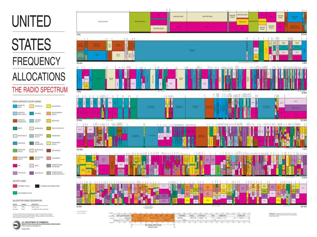
18 Radio-frequency spectrum Commercially exploited bands m/s c f Frequency Wavelength


 is responsible for")
 in Europe")
 In Thailand by the National Telecommunications")

19 Spectrum Allocation Spectral resource is limited. Most countries have government agencies responsible for allocating and controlling the use of the radio spectrum. Commercial spectral allocation is governed globally by the International Telecommunications Union (ITU) ITU Radiocommunication Sector (ITU-R) is responsible for radio communication. in the U.S. by the Federal Communications Commission (FCC) in Europe by the European Telecommunications Standards Institute (ETSI) In Thailand by the National Telecommunications Commission (NTC; สาน กงานคณะกรรมการก จการโทรคมนาคมแห งชาต ; กทช.) Blocks of spectrum are now commonly assigned through spectral auctions to the highest bidder. 19

20 20 US licensed spectrum
21 Unlicensed bands In addition to spectral auctions, spectrum can be set aside in specific frequency bands that are free to use with a license according to a specific set of etiquette rules. The purpose of these unlicensed bands is to encourage innovation and low-cost implementation. Many extremely successful wireless systems operate in unlicensed bands, including wireless LANs, Bluetooth, and cordless phones. A major difficulty is that they can be killed by their own success. If many unlicensed devices in the same band are used in close proximity, they generate much interference to each other, which can make the band unusable. 21

22 Unlicensed bands (2) Unlicensed spectrum is allocated by the governing body within a given country. Often countries try to match their frequency allocation for unlicensed use so that technology developed for that spectrum is compatible worldwide. The following table shows the unlicensed spectrum allocations in the U.S. 22
23 Licensed vs. Unlicensed Spectra Licensed Unlicensed 23 Typically nationwide Over a period of a few years From the spectrum regulatory agency Bandwidth is very expensive No hard constraints on the power transmitted within the licensed spectrum but the power is expected to decay rapidly outside. Provide immunity from any kind of interference outside of the system itself For experimental systems and to aid development of new wireless technologies Very cheap to transmit on There is a maximum power constraint over the entire spectrum. Have to deal with interference
24 24


25 Thailand Freq. Allocations Chart 25
26 26 Spectrum Allocation (Final Words) Spectrum is a scarce resource. Spectrum is allocated in chunks in frequency domain. Chunks are licensed to (cellular/wireless) operators. FDMA All cellular phone networks worldwide use a portion of the radio frequency spectrum designated as ultra high frequency (UHF). The UHF band is also shared with television, Wi-Fi and Bluetooth transmission. Due to historical reasons, radio frequencies used for cellular networks differ in the Americas, Europe, and Asia. Frequency bands recommended by ITU-R (in June 2003) for terrestrial Mobile telecommunication IMT-2000: MHz MHz MHz MHz Within a single cellular operator, the chunk is further divided into many channels. Each channel has its own band of frequency.
27 Caution Mobile networks based on different standards may use the same frequency chunk. For example, AMPS, D-AMPS, N-AMPS and IS-95 all use the 800 MHz frequency chunk. This is achieved by the use of different channels. 27
28 Chapter 4 Multiple Access 4.4 FDMA and TDMA 28 Office Hours: BKD Tuesday 14:00-16:00 Thursday 9:30-11:30
29 Multiple Access Techniques Allow many mobile users to share simultaneously a finite amount of radio spectrum. For high quality communications, this must be done without severe degradation in the performance of the system. Important access techniques 1. Frequency division multiple access (FDMA) 2. Time division multiple access (TDMA) 3. Spread spectrum multiple access (SSMA) Frequency Hopped Multiple Access (FHMA) Code division multiple access (CDMA) 4. Space division multiple access (SDMA) 5. Random access ALOHA 29
30 Frequency division multiple access (FDMA) The oldest multiple access scheme for wireless communications. Used exclusively for multiple access in 1G down to individual resource units or physical channels. Assign individual channels to individual users. Different carrier frequency is assigned to each user so that the resulting spectra do not overlap. During the period of the call, no other user can share the same channel. Band-pass filtering (or heterodyning) enables separate demodulation of each channel. 30
31 FDMA (2) If an FDMA channel is not in use, then it sits idle and cannot be used by other users to increase or share capacity. It is essentially a wasted resource. In FDD systems. the users are assigned a channel as a pair of frequencies. 31
32 Time division multiple access (TDMA) Divide the radio spectrum into time slots. In each slot only one user is allowed to either transmit or receive. A channel may be thought of as a particular time slot that reoccurs every frame, where N time slots comprise a frame. Transmit data in a buffer-and-burst method The transmission for any user is non-continuous. Digital data and digital modulation must be used with TDMA. This results in low battery consumption, since the subscriber transmitter can be turned off when not in use (which is most of the time). An obvious choice in the 1980s for digital mobile communications. 32

33 Frequency-Domain Analysis j2 ft0 j2 f0t Shifting Properties: g t t e G f e g t G f f Modulation: m t cos 2 f t M f f M f f c c c
34 Spectrum of Digital Data C f This is also the spectrum of c t kt for any k. 1 0, c t A t T A A 1, T f [Hz] m = [-1,-1,1,-1,-1,1,1,-1,-1,-1,1,-1,-1,1,-1,1,1,-1,-1,-1,-1,1,-1,-1,-1,-1,-1,1,-1,1] S f A -A st T t t f [Hz] n 1 n 1 34 k s t m c t kt S f C f m e k 0 k 0 k j2 fkt
35 TDMA Spectrum C f 1 0, c t A t T A A 1, T f [Hz] m = [-1,-1,1,-1,-1,1,1,-1,-1,-1,1,-1,-1,1,-1,1,1,-1,-1,-1,-1,1,-1,-1,-1,-1,-1,1,-1,1] S f A -A st T t t f [Hz] n 1 n 1 35 k s t m c t kt S f C f m e k 0 k 0 k j2 fkt

36 36 FDMA vs. TDMA
37 37 Tradeoffs TDMA transmissions are slotted This requires the receivers to be synchronized for each data burst. Guard slots are necessary to separate users. This results in larger overheads. FDMA allows completely uncoordinated transmission in the time domain No time synchronization among users is required. The complexity of FDMA mobile systems is lower when compared to TDMA systems, though this is changing as digital signal processing methods improve for TDMA. Since FDMA is a continuous transmission scheme, fewer bits are needed for overhead purposes (such as synchronization and framing bits) as compared to TDMA. FDMA needs to use costly bandpass filters. For TDMA, no filters are required to separate individual physical channels.


38 Guard Band vs. Guard Time FDMA TDMA 38

![2, Heine, 1998] GSM utilizes a combination](/docs-images/92/110338679/images/39-2.jpg "of FDMA and TDMA Two-dimensional channel")

39 Example: GSM FDMA GSM FDMA/TDMA with one active time slot 39 [Figure 7.2, Heine, 1998] GSM utilizes a combination of FDMA and TDMA Two-dimensional channel structure Each narrowband channel has bandwidth 200 khz. Time is divided into slots of length T =577 s.
 physical channels (in fullrate configuration). 40 [Figure 7.")
40 The FDMA/TDMA structure of GSM In full-rate configuration, eight time slots (TSs) are mapped on every frequency. A BS with 6 carriers, as shown here, has 48 (8 times 6) physical channels (in fullrate configuration). 40 [Figure 7.1, Heine, 1998]
41 Classifications of Medium Access Control (MAC) 41
42 42
43 Chapter 4 Multiple Access 4.5 DSSS 43 Office Hours: BKD Tuesday 14:00-16:00 Thursday 9:30-11:30
44 Spread spectrum (SS) Historically spread spectrum was developed for secure communication and military uses. Spread spectrum signals have the following characteristics: Difficult to intercept for an unauthorized person. Easily hidden. For an unauthorized person, it is difficult to even detect their presence in many cases. Resistant to jamming. Provide a measure of immunity to distortion due to multipath propagation. Asynchronous multiple-access capability. Wide bandwidth of spread spectrum signals is useful for location and timing acquisition. 44
45 Spread spectrum: Applications First achieve widespread use in military applications due to its inherent property of hiding the spread signal below the noise floor during transmission, its resistance to narrowband jamming and interference, and its low probability of detection and interception. The narrowband interference resistance has made spread spectrum common in cordless phones. The basis for both 2nd and 3rd generation cellular systems as well as 2nd generation wireless LANs. The ISI rejection and bandwidth sharing capabilities of spread spectrum are very desirable in these systems 45
46 Spread spectrum conditions Spread spectrum refers to any system that satisfies the following conditions [Lathi, 1998, p 406]: 1. The spread spectrum may be viewed as a kind of modulation scheme in which the modulated (spread spectrum) signal bandwidth is much greater than the message (baseband) signal bandwidth. 2. The spectral spreading is performed by a code that is independent of the message signal. This same code is also used at the receiver to despread the received signal in order to recover the message signal (from the spread spectrum signal). In secure communication, this code is known only to the person(s) for whom the message is intended. 46 [R. Pickholtz, D. Schilling, L. Milstein, Theory of Spread-Spectrum Communications - A Tutorial, IEEE Trans. Commun., Vol. 30, pp , May 1982.]
47 Spread spectrum (2) The spread spectrum scheme increases the bandwidth of the message signal by a factor N, called the processing gain. In practice spread spectrum systems have processing gains on the order of [Goldsmith, 2005, p 379] Although we use much higher BW for a spread spectrum signal, we can also multiplex large numbers of such signals over the same band. Many users can share the same spread spectrum bandwidth without interfering with one another. Achieved by assigning different code to each user. Frequency bands can be reused without regard to the separation distance of the users. 47
48 SSMA, CDMA, DS/SS Single User SSMA Multi-access TDMA DS/SS CDMA FDMA SDMA 48
 2 y t c t m t c t m t (Correlation) 1 Message signal (polar binary signal) Polar signal representing")
49 DS/SS System Useful even for single user! (Integrator) 2 y t c t m t c t m t (Correlation) 1 Message signal (polar binary signal) Polar signal representing psuedonoise (PN) sequence. (Think of this as a pseudorandom carrier) 49
50 Spread spectrum modem 50 [Viterbi, 1995, Fig. 1.2]
51 51 DS/SS The spectral spreading signal c(t) is a pseudorandom signal Appear to be unpredictable Can be generated by deterministic means (hence, pseudorandom) The bit rate of c(t) is chosen to be much higher then the bit rate of m(t). The basic pulse in c(t) is called the chip. The bit rate of c(t) is known as the chip rate. The auto correlation function of c(t) is very narrow. Small similarity with its delayed version Remark: In multiuser (CDMA) setting, the cross-correlation between any two codes c 1 (t) and c 2 (t) is very small Negligible interference between various multiplexed signals. Notice that the process of detection (despreading) is identical to the process of spectral spreading. Recall that for DSB-SC, we have a similar situation in that the modulation and demodulation processes are identical (except for the output filter).
52 Frequency-Domain Analysis j2 ft0 j2 f0t Shifting Properties: g t t e G f e g t G f f Modulation: m t cos 2 f t M f f M f f c c c
53 DS/SS: Secure Communication Secure communication Signal can be detected only by authorized person(s) who know the pseudorandom code used at the transmitter. Signal spectrum is spread over a very wide band, the signal PSD is very small, which makes it easier to hide the signal within the noise floor 53
. The jamming signal i(t) is spread to yield i(t)c(t). Using a LPF, can recover m(t) with only a small fraction of the power from i(t).")
54 DS/SS: Jamming Resistance 54 y t i t c t m t c 2 t i t c t m t i t c t Jamming Resistance / Narrowband Interference rejection The decoder despreads the signal y(t) to yield m(t). The jamming signal i(t) is spread to yield i(t)c(t). Using a LPF, can recover m(t) with only a small fraction of the power from i(t). Caution: Channel noise will not spread.
55 DS/SS: Multipath Fading Immunity The signal received from any undesired path is a delayed version of the DS/SS signal. DS/SS signal has a property of low autocorrelation (small similarity) with its delayed version, especially if the delay is of more than one chip duration. The delayed signal, looking more like an interfering signal, will not be despread by c(t) effectively minimizes the effect of the multipath signals. What is more interesting is that DSISS cannot only mitigate but may also exploit the multipath propagation effect. This is accomplished by a Rake receiver. This receive designed as to coherently combine the energy from several multipath components, which increases the received signal power and thus provides a form of diversity reception. The rake receiver consists of a bank of correlation receivers, with each individual receiver correlating with a different arriving multipath component. By adjusting the delays, the individual multipath components can be made to add coherently rather than destructively. 55
56 Chapter 4 Multiple Access 4.6 m-sequence 56 Office Hours: BKD Tuesday 14:00-16:00 Thursday 9:30-11:30
57 Binary Random Sequences While DSSS chip sequences must be generated deterministically, properties of binary random sequences are useful to gain insight into deterministic sequence design. A random binary chip sequences consists of i.i.d. bit values with probability one half for a one or a zero. Also known as Bernoulli sequences, coin-flipping sequences A random sequence of length N can be generated, for example, by flipping a fair coin N times as setting the bit to a one for heads and a zero for tails. 57
58 Pseudorandom Sequence Key randomness properties [Golomb, 1967]]: Binary random sequences with length N asymptotically large have a number of the properties desired in spreading codes Balanced property of a code: Equal number of ones and zeros. Run length property of a code: The run length is generally short. half of all runs are of length 1 a fraction 1/2 n of all runs of length n (Geometric) Shift property of a code: If they are shifted by any nonzero number of elements, the resulting sequence will have half its elements the same as in the original sequence, and half its elements different from the original sequence. A deterministic sequence that has the balanced, run length, and shift properties as it grows asymptotically large is referred to as a pseudorandom sequence (noiselike signal). 58 Note: A run is a subsequence of identical symbols within the sequence.
59 Pseudonoise (PN) signature sequence Ideally, one would prefer a random binary sequence as the spreading sequence. However, practical synchronization requirements in the receiver force one to use periodic Pseudorandom binary sequences. m-sequences Gold codes Kasami sequences Quaternary sequences Walsh functions 59
60 m-sequences (1) Maximal-length sequences A type of cyclic code Generated and characterized by a generator polynomial Properties can be derived using algebraic coding theory Simple to generate with linear feedback shift-register (LFSR) circuits Automated Approximate a random binary sequence in the sense that shifted versions of itself are approximately uncorrelated. Relatively easy to intercept and regenerate by an unintended receiver 60
![(See Section 13.4.1 in [Lathi, 1998]) m-sequence generator The feedback taps in the feedback shift register are selected to correspond to the coefficients of a primitive polynomial.](/docs-images/92/110338679/images/61-0.jpg "Binary sequences drawn from the alphabet {0,1} are shifted through the shift register in response to clock pulses.")
61 (See Section in [Lathi, 1998]) m-sequence generator The feedback taps in the feedback shift register are selected to correspond to the coefficients of a primitive polynomial. Binary sequences drawn from the alphabet {0,1} are shifted through the shift register in response to clock pulses. The particular 1s and 0s occupying the shift register stages after a clock pulse are called states. CLK (Degree: r = 3) The g i s are coefficients of a primitive polynomial signifies closed or a connection and 0 signifies open or no connection.
62 GF(2) Galois field (finite field) of two elements Consist of the symbols 0 and 1 and the (binary) operations of modulo-2 addition (XOR) and modulo-2 multiplication. The operations are defined by 62
63 m-sequences: More properties The contents of the shift register will cycle over all possible 2 r -1 nonzero states before repeating. Contain one more 1 than 0 Sum of two (cyclic-)shifted m-sequences is another (cyclic-)shift of the same m-sequence If a window of width r is slid along an m-sequence for N = 2 r -1 shifts, each r- tuple except the all-zeros r-tuple will appear exactly once For any m-sequence, there are One run of ones of length r One run of zeros of length r-1 One run of ones and one run of zeroes of length r-2 Two runs of ones and two runs of zeros of length r-3 Four runs of ones and four runs of zeros of length r-4 2 r-3 runs of ones and 2 r-3 runs of zeros of length 1 63 [S.W. Golomb, Shift Register Sequences, Holden-Day, San Francisco, 1967.]
64 Ex: Properties of m-sequence Runs: ,0 0 phase shift: phase shift: phase shift: phase shift: phase shift: phase shift: phase shift: =
65 Ex: Properties of m-sequence (con t) = 31-chip m-sequence Runs: There are 16 runs. 65


66 Nonmaximal linear feedback shift register 3 2 x x x 1 [Torrieri, 2005, Fig 2.8] 66 Complete state diagrams
67 m-sequences (con t) In actual transmission, we will map 0 and 1 to +1 and = -1 67
")


68 Autocorrelation and PSD (Normalized) autocorrelations of maximal sequence and random binary sequence. Power spectral density of maximal sequence. [Torrieri, 2005, Fig 2.9] 68 [Torrieri, 2005, Fig 2.10]
69 Two configurations of m-sequence generators output High-speed linear feedback shift-register generator output Low-speed linear feedback shift-register generator (standard form) [Ziemer, 2007, Fig. 5] [Torrieri,2005, Fig. 2.7] 69
70 Chapter CDMA 70 Office Hours: BKD Tuesday 14:00-16:00 Thursday 9:30-11:30
71 SSMA For spread spectrum systems with multiple users, codes such as Gold, Kasami, or Walsh codes are used instead of maximal length codes Superior cross-correlation properties. Worse auto-correlation than maximal length codes. The autocorrelation function of the spreading code determines its multipath rejection properties. 71


72 72 Code Division Multiple Access (CDMA) Qualcomm Founders: two of the most eminent engineers in the world of mobile radio Irwin Jacobs is the chairman and founder Andrew J. Viterbi is the co-founder Same person that invented the Viterbi algorithm for decoding convolutionally encoded data. 1991: Qualcomm announced that it had invented a new cellular system based on CDMA that the capacity of this system was 20 or so times greater than any other cellular system in existence However, not all of the world was particularly pleased by this apparent breakthrough in particular, GSM manufacturers became concerned that they would start to lose market share to this new system. The result was continual and vociferous argument between Qualcomm and the GSM manufacturers.
73 73 CDMA One way to achieve SSMA May utilize Direct Sequence Spread Spectrum (DS/SS) Direct sequence is not the only spread-spectrum signaling format suitable for CDMA All users use the same carrier frequency and may transmit simultaneously. Not to be confused with error-correcting codes that add redundancy to combat channel noise and distortion Users are assigned different signature waveforms or code or codeword or spreading signal The narrowband message signal is multiplied (modulated) by the spreading signal which has a very large bandwidth (orders of magnitudes greater than the data rate of the message). Each user s codeword is approximately orthogonal to all other codewords. Should not be confused with the mobile phone standards called cdmaone (Qualcomm s IS-95) and CDMA2000 (Qualcomm s IS-2000) (which are often referred to as simply "CDMA") These standards use CDMA as an underlying channel access method.
, they have a number of properties that make them highly suboptimal for exploiting the multiuser")

74 DSSS and Maximum-length Codes Maximal length codes have excellent auto-correlation properties (for ISI rejection), they have a number of properties that make them highly suboptimal for exploiting the multiuser capabilities of spread spectrum. There are only a small number of maximal length codes of a given length. Moreover, maximal length codes generally have relatively poor cross-correlation properties, at least for some sets of codes. 74
75 75 CDMA One way to achieve SSMA May utilize Direct Sequence Spread Spectrum (DS/SS) Direct sequence is not the only spread-spectrum signaling format suitable for CDMA All users use the same carrier frequency and may transmit simultaneously. Not to be confused with error-correcting codes that add redundancy to combat channel noise and distortion Users are assigned different signature waveforms or code or codeword or spreading signal The narrowband message signal is multiplied (modulated) by the spreading signal which has a very large bandwidth (orders of magnitudes greater than the data rate of the message). Each user s codeword is approximately orthogonal to all other codewords. Should not be confused with the mobile phone standards called cdmaone (Qualcomm s IS-95) and CDMA2000 (Qualcomm s IS-2000) (which are often referred to as simply "CDMA") These standards use CDMA as an underlying channel access method.
: sin t t 2 k 1 and cos 2 k 2 on 0, T T T e t j2 n T")
76 Vector: 76 Orthogonality Two vectors/functions are orthogonal if their inner product is zero. The symbol a b is used to denote orthogonality. 1 1 n * * k k k 1 a n b n a, b a b a b 0 Time-domain: *, 0 a b a t b t dt Frequency domain: * A, B A f B f df 0 * Example (Fourier Series): sin t t 2 k 1 and cos 2 k 2 on 0, T T T e t j2 n T Example: Complex conjugate t 3 and 5 t t on 1,1 9 on 0, T
77 Parseval s theorem * * x, y x t y t dt X f Y f df X, Y If x t y t, then X f Y f. 77
78 Recall: TDMA Spectrum C f 1 0, c t A t T A A 1, T f [Hz] m = [-1,-1,1,-1,-1,1,1,-1,-1,-1,1,-1,-1,1,-1,1,1,-1,-1,-1,-1,1,-1,-1,-1,-1,-1,1,-1,1] S f A -A st T t t f [Hz] n 1 n 1 78 k s t m c t kt S f C f m e k 0 k 0 k j2 fkt
79 CDMA Reception free from inter-channel interference is a consequence of the use of orthogonal signaling. This can be accomplished by signals that overlap both in time and in frequency. Orthogonal (real-valued) signals: Inner product, Cross-correlation Special case: TDMA T The signature waveforms do not overlap in the time domain. c, c c t c t dt 0 79
80 CDMA: Simplified Example An example of four mutually orthogonal digital signals. 80
81 CDMA (2) The receiver performs a time correlation operation to detect only the specific desired codeword. All other codewords appear as noise due to decorrelation. For detection of the message signal, the receiver needs to know the codeword used by the transmitter. Each user operates independently with no knowledge of the other users. Unlike TDMA or FDMA, CDMA has a soft capacity limit. Increasing the number of users in a CDMA system raises the noise floor in a linear manner. There is no absolute limit on the number of users in CDMA. Rather, the system performance gradually degrades for all users as the number of users is increased and improves as the number of users is decreased. 81
82 CDMA: Simplified Example (1) c1 t T t c2 t T t [Figure 1.6, Verdu, 1998] 82
83 CDMA: Simplified Example (1) con t 1 C 1 (f) f [Hz] C 2 (f) f [Hz] 83
84 CDMA: DS/SS The receiver performs a time correlation operation to detect only the specific desired codeword. All other codewords appear as noise due to decorrelation. For detection of the message signal, the receiver needs to know the codeword used by the transmitter. Each user operates independently with no knowledge of the other users. Unlike TDMA or FDMA, CDMA has a soft capacity limit. Increasing the number of users in a CDMA system raises the noise floor in a linear manner. There is no absolute limit on the number of users in CDMA. Rather, the system performance gradually degrades for all users as the number of users is increased and improves as the number of users is decreased. 84
85 Orthogonality in Communication CDMA TDMA FDMA 1 1 s t S c t S f S C f k k k k k 0 k s t S c t kt S f C f S e k s k k 0 k 0 where c(t) is time-limited to [0,T]. This is a special case of CDMA with c t c t kt 1 S f S C f k f k 0 k where C(f) is frequency-limited to [0, f]. This is a special case of CDMA with C f C f k f k k s where j2 fkt s The c k are non-overlapping in time domain. c k c k The C k are non-overlapping in freq. domain.
86 Analogy [Tanenbaum, 2003] An airport lounge with many pairs of people conversing. TDMA is comparable to all the people being in the middle of the room but taking turns speaking. FDMA is comparable to the people being in widely separated clumps, each clump holding its own conversation at the same time as, but still independent of, the others. CDMA is comparable to everybody being in the middle of the room talking at once, but with each pair in a different language. The French-speaking couple just hones in on the French, rejecting everything that is not French as noise. Thus, the key to CDMA is to be able to extract the desired signal while rejecting everything else as random noise. 86
87 CDMA: Near-Far Problem At first, CDMA did not appear to be suitable for mobile communication systems because of this problem. Occur when many mobile users share the same channel. In an uplink, the signals received from each user at the receiver travel through different channels. This gives rise to the near-far effect, where users that are close to the uplink receiver can cause a great deal of interference to user s farther away. In general, the strongest received mobile signal will capture the demodulator at a base station. Stronger received signal levels raise the noise floor at the base station demodulators for the weaker signals, thereby decreasing the probability that weaker signals will be received. Fast power control mechanisms solve this problem. Regulate the transmit power of individual terminals in a manner that received power levels are balanced at the base station. 87
88 Problem of CDMA The spreading sequences of different users are not exactly orthogonal In a mobile environment, multipath receptions may contribute to the interference power for each mobile station. In the despreading of a particular code, non-zero contributions to the receiver decision statistic for a desired user arise from the transmissions of other users in the system. 88
89 89 How many orthogonal signals? No signal can be both strictly time-limited and strictly bandlimited. We adopt a softer definition of bandwidth and/or duration (e.g., the percentage of energy outside the band [-B, B] or outside the time interval [0, T] not exceeding a given bound. Q: How many mutually orthogonal signals with (approximate) duration T and (approximate) bandwidth B can be constructed? A: About 2TB No explicit answer in terms of T, B, and is known. Unless the product TB is small. A K-user orthogonal CDMA system employing antipodal modulation at the rate of R bits per second requires bandwidth approximately equal to 1 B RK 2
90 Chapter 4 Multiple Access 4.8 Synchronous CDMA 90 Office Hours: BKD Tuesday 14:00-16:00 Thursday 9:30-11:30
91 Synchronous CDMA Model Timing is important for orthogonality It is not possible to obtain orthogonal codes for asynchronous users. For synchronous users there is only a finite number of spreading codes that are orthogonal within any given bandwidth. Bit epochs are aligned at the receiver Require Closed-loop timing control or Providing the transmitters with access to a common clock (such as the Global Positioning System) 91
![Walsh Functions [Walsh, 1923] Walsh codes are used in second- (2G)](/docs-images/92/110338679/images/92-0.jpg "and thirdgeneration (3G) cellular radio systems for providing")
 [Lee and Miller, 1998,")
92 Walsh Functions [Walsh, 1923] Walsh codes are used in second- (2G) and thirdgeneration (3G) cellular radio systems for providing channelization A set of Walsh functions can be ordered according to the number of zero crossing (sign changes) [Lee and Miller, 1998, Fig. 5.1] 92

93 Walsh Functions (2) Orthogonality Once we know how to generate these Walsh functions of any order N, we can use them in N-channel orthogonal multiplexing applications. 93
94 94 Walsh Sequences The Walsh functions, expressed in terms of 1 values, form a group under the multiplication operation (multiplicative group). The Walsh sequences, expressed in terms of (0, 1) values, form a group under modulo-2 addition (additive group). Closure property: W t W t W t i j r W W W i j r


95 Walsh sequences of order What s wrong with this list?! [Lee and Miller, 1998, Table 5.2]
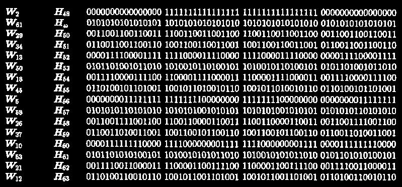
96 96 Walsh Function Generation The Walsh functions can be generated (or computed) by many methods. We can construct the Walsh functions by: Using Rademacher functions; Using Hadamard matrices; Exploiting the symmetry properties of Walsh functions themselves. The Hadamard matrix is a square array of plus and minus ones, {+1, -1}, whose rows and columns are mutually orthogonal. If the first row and first column contain only plus ones, the matrix is said to be in normal form. We can replace +1 with 0 and -1 with 1 to express the Hadamard matrix using the logic elements (0, 1). The 2 2 Hadamard matrix of order 2 is H
97 Hadamard matrix (1) 97 Caution: Some textbooks write this symbol as. It is not the regular matrix multiplication
98 98 Hadamard matrix (2)


99 Hadamard matrix: Examples Caution: This is not the usual matrix multiplication! In MATLAB, use hadamard(k) 99


100 Two ways to get H 8 from H 2 and H 4 H 2 H 4 H8 H 2 H 4 H8 H 4 H 2 100
101 Walsh Hadamard Sequences All the row (or column) sequences of Hadamard matrices are Walsh sequences if the order is N = 2 t. The Walsh functions generated by the Hadamard matrix method are not indexed according to the number of sign changes. Used in synchronous CDMA It is possible to synchronize users on the downlink, where all signals originate from the same transmitter. It is more challenging to synchronize users in the uplink, since they are not co-located. Asynchronous CDMA 101
102 Hadamard Matrix in MATLAB We use the hadamard function in MATLAB to generate Walsh functions of length eight. N = 8; % Length of Walsh (Hadamard) functions hadamardmatrix = hadamard(n) hadamardmatrix = The Walsh functions in the matrix are not arranged in increasing order of their sequencies or number of zerocrossings (i.e. 'sequency order').
103 Walsh Matrix in MATLAB The Walsh matrix, which contains the Walsh functions along the rows or columns in the increasing order of their sequencies is obtained by changing the index of the hadamardmatrix as follows. HadIdx = 0:N-1; M = log2(n)+1; % Hadamard index % Number of bits to represent the index Each column of the sequency index (in binary format) is given by the modulo-2 addition of columns of the bit-reversed Hadamard index (in binary format). binhadidx = fliplr(dec2bin(hadidx,m)); % Bit reversing of the binary index binhadidx = uint8(binhadidx)-uint8('0'); % Convert from char to integer array binseqidx = zeros(n,m-1,'uint8'); % Pre-allocate memory for k = M:-1:2 % Binary sequency index binseqidx(:,k) = xor(binhadidx(:,k),binhadidx(:,k-1)); end SeqIdx = bin2dec(int2str(binseqidx)); % Binary to integer sequency index walshmatrix = hadamardmatrix(seqidx+1,:) % 1-based indexing walshmatrix =
104 CDMA via Hadamard Matrix This signal is formed using weighted Walsh functions, so the WHT should return non-zero values equal to the weights at the respective indices Encoding Decoding N = 8; H = hadamard(n); % Hadamard matrix % Construct a signal by adding a few weighted Walsh functions x = 8.*H(1,:) + 12.*H(3,:) + 18.*H(5,:) + 10.*H(8,:); y = fwht(x,n,'hadamard') y = Discrete Walsh-Hadamard transform Specify the order of the Walsh-Hadamard transform coefficients. ORDERING can be 'sequency', 'hadamard' or 'dyadic'. Default ORDERING type is 'sequency'. 104 Note that y 1 T N xh
105 Chapter 4 Multiple Access 4.9 IS Office Hours: BKD Tuesday 14:00-16:00 Thursday 9:30-11:30
106 Evolution of cellular network [Abu-Rgheff, 2007] 106


107 IS-95 System Based on direct sequence CDMA (DS-CDMA) First CDMA-based digital cellular standard. The brand name for IS-95 is cdmaone. Also known as TIA-EIA-95. Proposed by Qualcomm in 1989 and adopted in North America Now being replaced by IS-2000 (CDMA2000) 1.25 MHz Channel BW Mb/s chip rate Walsh functions of order 64 are extensively used in the IS-95 system. Remarks IS-95B = cdmaone Ugrade IS-95A Can carry data at rates up to 14.4 kbps for IS-95A and 115 kbps for IS-95B. 107


![8]](/docs-images/92/110338679/images/108-4.jpg)
108 64-ary Walsh Functions 108 [Lee and Miller, 1998, Table 5.8]
109 Walsh Sequences in IS-95 Forward link QPSK with a chip rate of 1,228,800 per second. The multiple access scheme is accomplished by the use of 64-bit spreading orthogonal Walsh sequences (functions). The (coded and interleaved) traffic channel signal symbols are multiplied with distinct repeating Walsh sequences that are assigned to each channel for the duration of the call. Every base stations is synchronized with a GPS receiver so transmissions are tightly controlled in time. Reverse link The Walsh sequences are employed as an orthogonal modulation code, which depends only on the data pattern (not channel), forming a 64-ary orthogonal modulation system. 109
110 110 IS-95 The reverse link is subject to near-far effects. More powerful error correction is employed on the reverse link. A rate 1/2 constraint length 9 convolutional code followed by an interleaver on the forward channel A rate 1/3 constraint length 9 convolutional code followed by an interleaver is used on the reverse link. Also with WH(6,64) Interleaving is utilized to avoid large burst errors, which can be very detrimental to convolutional codes. Power control. Use a subchannel on the forward link Every 1.25 ms the base station receiver estimates the signal strength of the mobile unit. If it is too high, the base transmits a 1 on the subchannel. If it is too low, it transmits a 0. In this way, the mobile station adjusts its power every 1.25 ms as necessary so as to reduce interference to other users.
111 IS-95: Increased Spectral Efficiency Improve frequency reuse. Narrow-band systems cannot use the same transmission frequency in adjacent cells because of the potential for interference. CDMA has inherent resistance to interference. N = 1 (theoretically) Although users from adjacent cells will contribute to interference level, their contribution will be significantly less than the interference from the same cell users. Frequency reuse efficiency increases by a factor of 4 to 6. When used to transmit voice signals, CDMA systems may exploit the fact that voice activity typically lies at somewhat less than 40%, thus reducing the amount of interference to 40% of its original value. 111
112 QCELP Qualcomm code-excited linear prediction algorithm Used for voice encoding. The voice coder exploits gaps and pauses in speech. The data rate is variable. To keep the symbol rate constant, whenever the bit rate falls below the peak bit rate of 9600 kbit/s, repetition is used to fill the gaps. For example, if the output of the voice coder (and subsequently the convolutional coder) falls to 2400 bit/s, the output is repeated three times before it is sent to the interleaver. Takes advantage of this repetition time by reducing the output power during three out of the four identical symbols by at least 20 db. In this way, the multiple-access interference is reduced. This voice activity gating reduces interference and increases overall capacity. 112

113 IS-95 base station transceiver (to provide privacy) 113
")
114 IS-95 terminal station transceiver (for FEC) 114
115 References J. S. Lee and L. E. Miller, CDMA Systems Engineering Handbook. Boston, MA: Artech House, Oct Chapter 4 and 5 R.E. Ziemer, Fundamentals of Spread Spectrum Modulation. Colorado Springs: Morgan & Claypool Publishers, 2007 Chapter 4 115
116 116
117 Chapter 4 Multiple Access 4.10 Async. CDMA: Gold codes and GPS 117 Office Hours: BKD Tuesday 14:00-16:00 Thursday 9:30-11:30
118 Asynchronous CDMA Model In cellular systems, the design of the reverse link (mobile-tobase station) is considerably simplified if the users need not be synchronized. It is possible to let the users transmit completely asynchronously in CDMA. Codes assigned to different users need to have low cross correlation with each other independent of the relative delays Gold codes 118
119 Gold codes Gold codes have worse autocorrelation properties than maximal-length codes, but better cross-correlation properties if properly designed. The chip sequences associated with a Gold code are produced by addition of two m-sequences. 119 [Ziemer, 2007, Fig. 9]
120 120 Orthogonality (a revisit) Downlinks May use orthogonal spreading codes such as Walsh-Hadamard codes Orthogonality can be degraded by multipath. Uplinks Generally use non-orthogonal codes due to the difficulty of user synchronization and the complexity of maintaining code orthogonality in uplinks with multipath. Little dynamic coordination of users in time or frequency is required Users can be separated by the code properties alone. There is a hard limit on how many orthogonal channels (orthogonal codes) can be obtained. For non-orthogonal codes, there is no hard limit. Non-orthogonal codes cause mutual interference between users. The more users, the higher the level of interference Degrade the performance of all the users. Non-orthogonal CDMA scheme also requires power control in the uplink to compensate for the near-far effect.
121 Near-far Effect Arise in the uplink because the channel gain between a user s transmitter and the receiver is different for different users. Suppose that one user is very close to his base station or access point, and another user very far away. If both users transmit at the same power level, then the interference from the close user will swamp the signal from the far user. Power control Make the received signal power of all users to be roughly the same Essentially inverts any attenuation and/or fading on the channel Each interferer must contribute an equal amount of power Eliminating the near-far effect 121

 anywhere on earth.")
 the next utility")
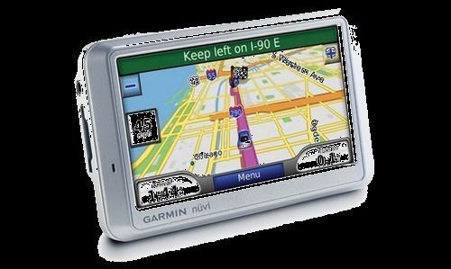
122 Global Positioning System (GPS) Original application in the military Allow a person to determine the time and the person's precise location (latitude, longitude, and altitude) anywhere on earth. The potential applications of GPS are so vast that it has been called (with some exaggeration) the next utility (similar to gas, water, and electricity). 122

123 GPS Satellite A minimum of 24 GPS satellites are in orbit at 20,200 kilometers (12,600 miles) above the Earth. The satellites are spaced so that from any point on Earth, at least four satellites will be above the horizon. 123
 Standard Positioning Service (SPS) The")

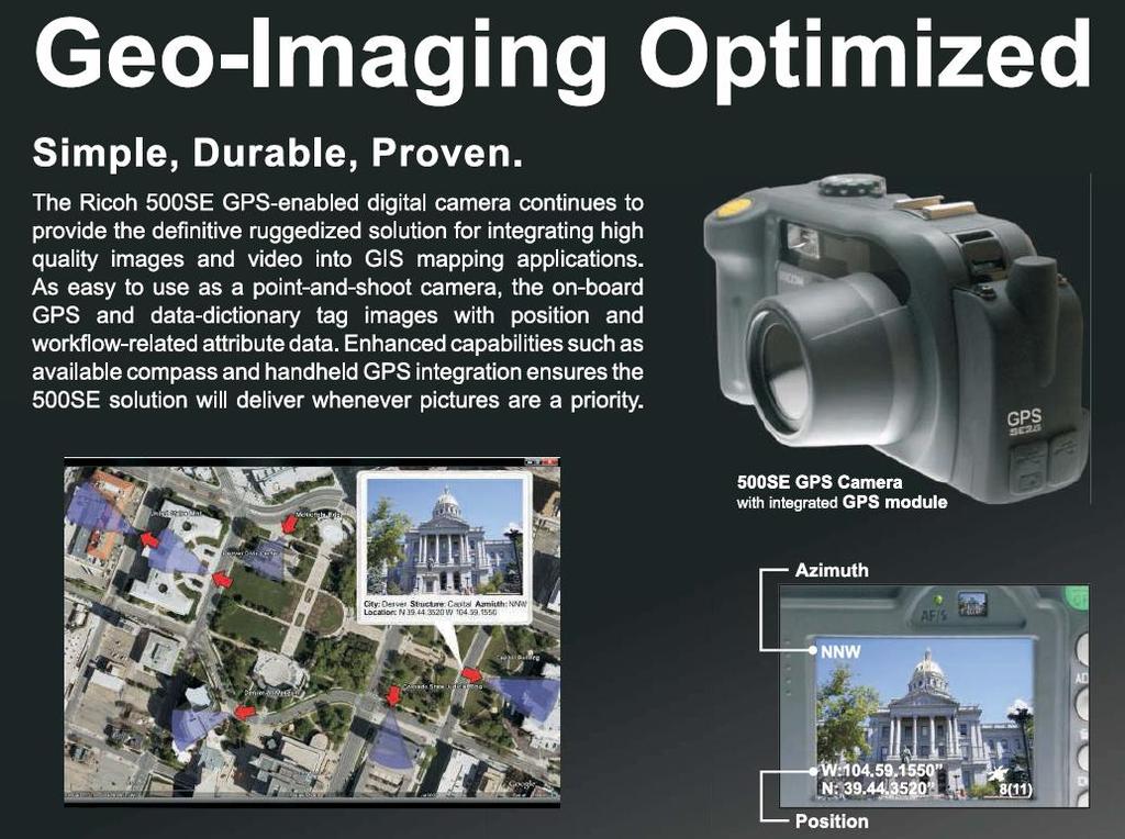
124 GPS and Gold codes Gold codes are used to distinguish the signals from different satellites Coarse Acquisition code (C/A) Standard Positioning Service (SPS) The message data is transmitted at 50 bits per second bits with a period of one millisecond. Positions of these feedback determine the satellite ID 124 [Plausinaitis]
125 125 Auto and cross correlation of C/A code
126 How GPS Works? A GPS receiver measuring its distance from a group of satellites in space which are acting as precise reference points. All the satellites have atomic clocks of unbelievable precision on board and are synchronized. The satellite are continuously transmitting the information about their location and time. GPS receiver on the ground is in synchronism with the satellites. Off by an (unknown) amount. For now, assume = 0. By measuring the propagation time, the receiver can compute distance d from that satellite. 126
127 GPS-Trilateration Intersection of three sphere narrows down the location to just two points. 127 [Lathi,1998, Fig. 9.6 ] In practice, there are four unknowns, the coordinates in the three-dimensional space of the user along with within the user s receiver. Need a distance measurement from a fourth satellite.


128 128
129 129
130 130


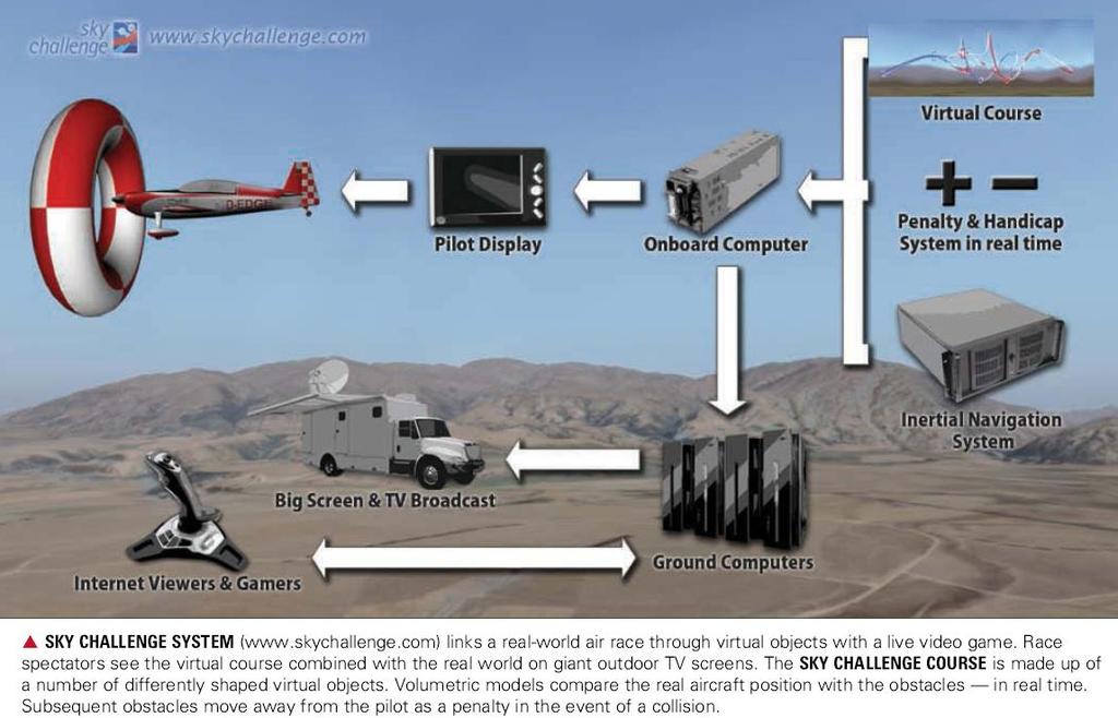
131 131 Sky Challenge, a real-time race between real and virtual aircraft. Pilots race actual aerobatics planes through a virtual course made up of 3-D objects that do not physically exist. Loading the course into a flight simulator on the ground and geographically linking it with the real world and simulated planes enables virtual pilots to race against realworld pilots in real time or after the race.
132 132
133 Chapter 4 Multiple Access 4.11 Other Remarks 133 Office Hours: BKD Tuesday 14:00-16:00 Thursday 9:30-11:30
134 FDMA never dies! Any CDMA or TDMA system will normally include an FDMA component, and can therefore be considered as a hybrid CDMA/FDMA or TDMA/FDMA system. In the relatively narrowband TDMA-based 2G systems with a small number of slots per frame D-AMPS: 30 khz carrier, three users per carrier GSM: 200 khz carrier, eight full-rate users per carrier FDMA still fulfills a role in providing multiple access, although not down to individual channels. 134

135 Space Division Multiple Access (SDMA) Control the radiated energy for each user in space. Use spot beam antennas. Sectorized antennas may be thought of as a primitive application of SDMA. 135
Mobile Communications TCS 455
 Mobile Communications TCS 455 Dr. Prapun Suksompong prapun@siit.tu.ac.th Lecture 21 1 Office Hours: BKD 3601-7 Tuesday 14:00-16:00 Thursday 9:30-11:30 Announcements Read Chapter 9: 9.1 9.5 HW5 is posted.
ECS455: Chapter 4 Multiple Access
 ECS455: Chapter 4 Multiple Access 4.4 DS/SS 1 Dr.Prapun Suksompong prapun.com/ecs455 Office Hours: BKD 3601-7 Wednesday 15:30-16:30 Friday 9:30-10:30 Spread spectrum (SS) Historically spread spectrum was
ECS455: Chapter 4 Multiple Access
 ECS455: Chapter 4 Multiple Access Asst. Prof. Dr. Prapun Suksompong prapun@siit.tu.ac.th 1 Office Hours: BKD 3601-7 Tuesday 9:30-10:30 Tuesday 13:30-14:30 Thursday 13:30-14:30 ECS455: Chapter 4 Multiple
ECS455: Chapter 4 Multiple Access
 ECS455: Chapter 4 Multiple Access 4.4 DS/SS 1 Dr.Prapun Suksompong prapun.com/ecs455 Office Hours: BKD 3601-7 Tuesday 9:30-10:30 Tuesday 13:30-14:30 Thursday 13:30-14:30 Spread spectrum (SS) Historically
ECS455: Chapter 4 Multiple Access
 ECS455: Chapter 4 Multiple Access 4.9 Async. CDMA: Gold codes and GPS 1 Dr.Prapun Suksompong prapun.com/ecs455 Office Hours: BKD 3601-7 Tuesday 9:30-10:30 Tuesday 13:30-14:30 Thursday 13:30-14:30 Asynchronous
Multiple Access Schemes
 Multiple Access Schemes Dr Yousef Dama Faculty of Engineering and Information Technology An-Najah National University 2016-2017 Why Multiple access schemes Multiple access schemes are used to allow many
Multiplexing Module W.tra.2
 Multiplexing Module W.tra.2 Dr.M.Y.Wu@CSE Shanghai Jiaotong University Shanghai, China Dr.W.Shu@ECE University of New Mexico Albuquerque, NM, USA 1 Multiplexing W.tra.2-2 Multiplexing shared medium at
SC - Single carrier systems One carrier carries data stream
 Digital modulation SC - Single carrier systems One carrier carries data stream MC - Multi-carrier systems Many carriers are used for data transmission. Data stream is divided into sub-streams and each
Spread Spectrum. Chapter 18. FHSS Frequency Hopping Spread Spectrum DSSS Direct Sequence Spread Spectrum DSSS using CDMA Code Division Multiple Access
 Spread Spectrum Chapter 18 FHSS Frequency Hopping Spread Spectrum DSSS Direct Sequence Spread Spectrum DSSS using CDMA Code Division Multiple Access Single Carrier The traditional way Transmitted signal
Multiple Access Techniques
 Multiple Access Techniques EE 442 Spring Semester Lecture 13 Multiple Access is the use of multiplexing techniques to provide communication service to multiple users over a single channel. It allows for
Lecture 9: Spread Spectrum Modulation Techniques
 Lecture 9: Spread Spectrum Modulation Techniques Spread spectrum (SS) modulation techniques employ a transmission bandwidth which is several orders of magnitude greater than the minimum required bandwidth
CDMA - QUESTIONS & ANSWERS
 CDMA - QUESTIONS & ANSWERS http://www.tutorialspoint.com/cdma/questions_and_answers.htm Copyright tutorialspoint.com 1. What is CDMA? CDMA stands for Code Division Multiple Access. It is a wireless technology
Part 3. Multiple Access Methods. p. 1 ELEC6040 Mobile Radio Communications, Dept. of E.E.E., HKU
 Part 3. Multiple Access Methods p. 1 ELEC6040 Mobile Radio Communications, Dept. of E.E.E., HKU Review of Multiple Access Methods Aim of multiple access To simultaneously support communications between
CDMA Principle and Measurement
 CDMA Principle and Measurement Concepts of CDMA CDMA Key Technologies CDMA Air Interface CDMA Measurement Basic Agilent Restricted Page 1 Cellular Access Methods Power Time Power Time FDMA Frequency Power
SPREAD SPECTRUM (SS) SIGNALS FOR DIGITAL COMMUNICATIONS
 SIGNALS FOR DIGITAL COMMUNICATIONS") Dr. Ali Muqaibel SPREAD SPECTRUM (SS) SIGNALS FOR DIGITAL COMMUNICATIONS VERSION 1.1 Dr. Ali Hussein Muqaibel 1 Introduction Narrow band signal (data) In Spread Spectrum, the bandwidth W is much greater
Dr. Ali Muqaibel SPREAD SPECTRUM (SS) SIGNALS FOR DIGITAL COMMUNICATIONS VERSION 1.1 Dr. Ali Hussein Muqaibel 1 Introduction Narrow band signal (data) In Spread Spectrum, the bandwidth W is much greater
ECS 455 Chapter 1 Introduction
 ECS 455 Chapter 1 Introduction 1.3 Spectrum Allocation 1 Dr.Prapun prapun.com/ecs455 Office Hours: BKD, 6th floor of Sirindhralai building Tuesday 14:20-15:20 Wednesday 14:20-15:20 Friday 9:15-10:15 Electromagnetic
Spread Spectrum Techniques
 0 Spread Spectrum Techniques Contents 1 1. Overview 2. Pseudonoise Sequences 3. Direct Sequence Spread Spectrum Systems 4. Frequency Hopping Systems 5. Synchronization 6. Applications 2 1. Overview Basic
1.4 Spectrum Allocation Office Hours: BKD Monday 9:20-10:20 Wednesday 9:20-10:20
 ECS 455 Chapter 1 Introduction & Review 1.4 Spectrum Allocation 1 Office Hours: BKD 3601-7 Monday 9:20-10:20 Wednesday 9:20-10:20 Electromagnetic Spectrum [Gosling, 1999, Fig 1.1] 2 8 3 10 m/s c f Frequency
WCDMA Basics Chapter 2 OBJECTIVES:
 WCDMA Basics Chapter 2 This chapter is designed to give the students a brief review of the WCDMA basics of the WCDMA Experimental System. This is meant as a review only as the WCDMA basics have already
ECE 476/ECE 501C/CS Wireless Communication Systems Winter Lecture 9: Multiple Access, GSM, and IS-95
 ECE 476/ECE 501C/CS 513 - Wireless Communication Systems Winter 2003 Lecture 9: Multiple Access, GSM, and IS-95 Outline: Two other important issues related to multiple access space division with smart
EEE 309 Communication Theory
 EEE 309 Communication Theory Semester: January 2016 Dr. Md. Farhad Hossain Associate Professor Department of EEE, BUET Email: mfarhadhossain@eee.buet.ac.bd Office: ECE 331, ECE Building Part 08 Multiplexing
CH 4. Air Interface of the IS-95A CDMA System
 CH 4. Air Interface of the IS-95A CDMA System 1 Contents Summary of IS-95A Physical Layer Parameters Forward Link Structure Pilot, Sync, Paging, and Traffic Channels Channel Coding, Interleaving, Data
Multiple Access System
 Multiple Access System TDMA and FDMA require a degree of coordination among users: FDMA users cannot transmit on the same frequency and TDMA users can transmit on the same frequency but not at the same
CHAPTER 6 SPREAD SPECTRUM. Xijun Wang
 CHAPTER 6 SPREAD SPECTRUM Xijun Wang WEEKLY READING 1. Goldsmith, Wireless Communications, Chapters 13 2. Tse, Fundamentals of Wireless Communication, Chapter 4 2 WHY SPREAD SPECTRUM n Increase signal
Spread Spectrum Signal for Digital Communications
 Wireless Information Transmission System Lab. Spread Spectrum Signal for Digital Communications Institute of Communications Engineering National Sun Yat-sen University Multiple Access Schemes Table of
Simple Algorithm in (older) Selection Diversity. Receiver Diversity Can we Do Better? Receiver Diversity Optimization.
 Selection Diversity. Receiver Diversity Can we Do Better? Receiver Diversity Optimization.") 18-452/18-750 Wireless Networks and Applications Lecture 6: Physical Layer Diversity and Coding Peter Steenkiste Carnegie Mellon University Spring Semester 2017 http://www.cs.cmu.edu/~prs/wirelesss17/
18-452/18-750 Wireless Networks and Applications Lecture 6: Physical Layer Diversity and Coding Peter Steenkiste Carnegie Mellon University Spring Semester 2017 http://www.cs.cmu.edu/~prs/wirelesss17/
CHAPTER 2. Instructor: Mr. Abhijit Parmar Course: Mobile Computing and Wireless Communication ( )
") CHAPTER 2 Instructor: Mr. Abhijit Parmar Course: Mobile Computing and Wireless Communication (2170710) Syllabus Chapter-2.4 Spread Spectrum Spread Spectrum SS was developed initially for military and intelligence
CHAPTER 2 Instructor: Mr. Abhijit Parmar Course: Mobile Computing and Wireless Communication (2170710) Syllabus Chapter-2.4 Spread Spectrum Spread Spectrum SS was developed initially for military and intelligence
UNIK4230: Mobile Communications. Abul Kaosher
 UNIK4230: Mobile Communications Abul Kaosher abul.kaosher@nsn.com Multiple Access Multiple Access Introduction FDMA (Frequency Division Multiple Access) TDMA (Time Division Multiple Access) CDMA (Code
CH 5. Air Interface of the IS-95A CDMA System
 CH 5. Air Interface of the IS-95A CDMA System 1 Contents Summary of IS-95A Physical Layer Parameters Forward Link Structure Pilot, Sync, Paging, and Traffic Channels Channel Coding, Interleaving, Data
Multiple Access Techniques for Wireless Communications
 Multiple Access Techniques for Wireless Communications Contents 1. Frequency Division Multiple Access (FDMA) 2. Time Division Multiple Access (TDMA) 3. Code Division Multiple Access (CDMA) 4. Space Division
Spread Spectrum: Definition
 Spread Spectrum: Definition refers to the expansion of signal bandwidth, by several orders of magnitude in some cases, which occurs when a key is attached to the communication channel an RF communications
Lecture 3 Cellular Systems
 Lecture 3 Cellular Systems I-Hsiang Wang ihwang@ntu.edu.tw 3/13, 2014 Cellular Systems: Additional Challenges So far: focus on point-to-point communication In a cellular system (network), additional issues
Mobile Communication Systems. Part 7- Multiplexing
 Mobile Communication Systems Part 7- Multiplexing Professor Z Ghassemlooy Faculty of Engineering and Environment University of Northumbria U.K. http://soe.ac.uk/ocr Contents Multiple Access Multiplexing
Chapter 7. Multiple Division Techniques
 Chapter 7 Multiple Division Techniques 1 Outline Frequency Division Multiple Access (FDMA) Division Multiple Access (TDMA) Code Division Multiple Access (CDMA) Comparison of FDMA, TDMA, and CDMA Walsh
Page 1. Overview : Wireless Networks Lecture 9: OFDM, WiMAX, LTE
 Overview 18-759: Wireless Networks Lecture 9: OFDM, WiMAX, LTE Dina Papagiannaki & Peter Steenkiste Departments of Computer Science and Electrical and Computer Engineering Spring Semester 2009 http://www.cs.cmu.edu/~prs/wireless09/
TELE4652 Mobile and Satellite Communication Systems
 TELE4652 Mobile and Satellite Communication Systems Lecture 10 IS-95 CDMA A second generation cellular standard, based on CDMA technology, was proposed by Qualcomm in the early 1990s. It was standardised
W-CDMA for UMTS Principles
 W-CDMA for UMTS Principles Introduction CDMA Background/ History Code Division Multiple Access (CDMA) Why CDMA? CDMA Principles / Spreading Codes Multi-path Radio Channel and Rake Receiver Problems to
Technical Aspects of LTE Part I: OFDM
 Technical Aspects of LTE Part I: OFDM By Mohammad Movahhedian, Ph.D., MIET, MIEEE m.movahhedian@mci.ir ITU regional workshop on Long-Term Evolution 9-11 Dec. 2013 Outline Motivation for LTE LTE Network
MODULATION AND MULTIPLE ACCESS TECHNIQUES
 1 MODULATION AND MULTIPLE ACCESS TECHNIQUES Networks and Communication Department Dr. Marwah Ahmed Outlines 2 Introduction Digital Transmission Digital Modulation Digital Transmission of Analog Signal
Code Division Multiple Access.
 Code Division Multiple Access Mobile telephony, using the concept of cellular architecture, are built based on GSM (Global System for Mobile communication) and IS-95(Intermediate Standard-95). CDMA allows
Channel partitioning protocols
 Wireless Networks a.y. 2010-2011 Channel partitioning protocols Giacinto Gelli DIBET gelli@unina.it 1 Outline Introduction Duplexing techniques FDD TDD Channel partitioning techniques FDMA TDMA CDMA Hybrid
ECE 5325/6325: Wireless Communication Systems Lecture Notes, Spring 2013
 ECE 5325/6325: Wireless Communication Systems Lecture Notes, Spring 2013 Lecture 17 Today: Spread Spectrum: (1) Frequency Hopping, (2) Direct Sequence Reading: Today Molisch 18.1, 18.2. Thu: MUSE Channel
An Overview of the QUALCOMM CDMA Digital Cellular Proposal
 An Overview of the QUALCOMM CDMA Digital Cellular Proposal Zeljko Zilic ELE 543S- Course Project Abstract.0 Introduction This paper describes a proposed Code Division Multiple Access (CDMA) digital cellular
Chapter 5 OFDM. Office Hours: BKD Tuesday 14:00-16:00 Thursday 9:30-11:30
 Chapter 5 OFDM 1 Office Hours: BKD 3601-7 Tuesday 14:00-16:00 Thursday 9:30-11:30 2 OFDM: Overview Let S 1, S 2,, S N be the information symbol. The discrete baseband OFDM modulated symbol can be expressed
CDMA Systems Engineering Handbook
 CDMA Systems Engineering Handbook Jhong Sam Lee Leonard E. Miller Artech House Boston London Table of Contents Preface xix CHAPTER 1: INTRODUCTION AND REVIEW OF SYSTEMS ANALYSIS BASICS 1 1.1 Introduction
Chapter 1 Acknowledgment:
 Chapter 1 Acknowledgment: This material is based on the slides formatted by Dr Sunilkumar S. Manvi and Dr Mahabaleshwar S. Kakkasageri, the authors of the textbook: Wireless and Mobile Networks, concepts
<3rd generation CDMA wireless systems>
 Page 1 Overview What is 3G? A brief overview of IS95 Key design choices for CDMA 3G systems. Bandwidth Modulation Coding Power Control
Multiple Access Technique Lecture 8
 Multiple Access Technique Lecture 8 Ir. Muhamad Asvial, MEng., PhD Center for Information and Communication Engineering Research Electrical Engineering Department University of Indonesia Kampus UI Depok,
Spread Spectrum Basics Spreading Codes IS-95 Features- Transmitter/Receiver Power Control Diversity Techniques RAKE Receiver Soft Handoff
 CDMA Mobile Communication & IS-95 1 Outline Spread Spectrum Basics Spreading Codes IS-95 Features- Transmitter/Receiver Power Control Diversity Techniques RAKE Receiver Soft Handoff 2 Spread Spectrum A
Lecture 8 Mul+user Systems
 Wireless Communications Lecture 8 Mul+user Systems Prof. Chun-Hung Liu Dept. of Electrical and Computer Engineering National Chiao Tung University Fall 2014 Outline Multiuser Systems (Chapter 14 of Goldsmith
Multiple Access Techniques
 Multiple Access Techniques Instructor: Prof. Dr. Noor M. Khan Department of Electrical Engineering, Faculty of Engineering, Mohammad Ali Jinnah University, Islamabad Campus, Islamabad, PAKISTAN Ph: +92
Implementation of Different Interleaving Techniques for Performance Evaluation of CDMA System
 Implementation of Different Interleaving Techniques for Performance Evaluation of CDMA System Anshu Aggarwal 1 and Vikas Mittal 2 1 Anshu Aggarwal is student of M.Tech. in the Department of Electronics
Chapter 7 Multiple Division Techniques for Traffic Channels
 Introduction to Wireless & Mobile Systems Chapter 7 Multiple Division Techniques for Traffic Channels Outline Introduction Concepts and Models for Multiple Divisions Frequency Division Multiple Access
CS 218 Fall 2003 October 23, 2003
 CS 218 Fall 2003 October 23, 2003 Cellular Wireless Networks AMPS (Analog) D-AMPS (TDMA) GSM CDMA Reference: Tanenbaum Chpt 2 (pg 153-169) Cellular Wireless Network Evolution First Generation: Analog AMPS:
DATA CHUNKING IN QUASI-SYNCHRONOUS DS-CDMA. A Thesis. presented to. the Faculty of California Polytechnic State University, San Luis Obispo
 DATA CHUNKING IN QUASI-SYNCHRONOUS DS-CDMA A Thesis presented to the Faculty of California Polytechnic State University, San Luis Obispo In Partial Fulfillment of the Requirements for the Degree Master
Chapter 2 Overview. Duplexing, Multiple Access - 1 -
 Chapter 2 Overview Part 1 (2 weeks ago) Digital Transmission System Frequencies, Spectrum Allocation Radio Propagation and Radio Channels Part 2 (last week) Modulation, Coding, Error Correction Part 3
Lecture LTE (4G) -Technologies used in 4G and 5G. Spread Spectrum Communications
 -Technologies used in 4G and 5G. Spread Spectrum Communications") COMM 907: Spread Spectrum Communications Lecture 10 - LTE (4G) -Technologies used in 4G and 5G The Need for LTE Long Term Evolution (LTE) With the growth of mobile data and mobile users, it becomes essential
COMM 907: Spread Spectrum Communications Lecture 10 - LTE (4G) -Technologies used in 4G and 5G The Need for LTE Long Term Evolution (LTE) With the growth of mobile data and mobile users, it becomes essential
Access Methods and Spectral Efficiency
 Access Methods and Spectral Efficiency Yousef Dama An-Najah National University Mobile Communications Access methods SDMA/FDMA/TDMA SDMA (Space Division Multiple Access) segment space into sectors, use
UNIT 4 Spread Spectrum and Multiple. Access Technique
 UNIT 4 Spread Spectrum and Multiple Access Technique Spread Spectrum lspread spectrumis a communication technique that spreads a narrowband communication signal over a wide range of frequencies for transmission
Multiple access techniques
 Multiple access techniques Narrowband and wideband systems FDMA TDMA CDMA /FHMA SDMA Random-access techniques Summary Wireless Systems 2015 Narrowband and wideband systems Coherence BW B coh 1/σ τ σ τ
Introduction to Wireless and Mobile Networking. Hung-Yu Wei g National Taiwan University
 Introduction to Wireless and Mobile Networking Lecture 3: Multiplexing, Multiple Access, and Frequency Reuse Hung-Yu Wei g National Taiwan University Multiplexing/Multiple Access Multiplexing Multiplexing
Medium Access Control. Wireless Networks: Guevara Noubir. Slides adapted from Mobile Communications by J. Schiller
 Wireless Networks: Medium Access Control Guevara Noubir Slides adapted from Mobile Communications by J. Schiller S200, COM3525 Wireless Networks Lecture 4, Motivation Can we apply media access methods
Lecture 2. Mobile Evolution Introduction to Spread Spectrum Systems. COMM 907:Spread Spectrum Communications
 COMM 907: Spread Spectrum Communications Lecture 2 Mobile Evolution Introduction to Spread Spectrum Systems Evolution of Mobile Telecommunications Evolution of Mobile Telecommunications Evolution of Mobile
RADIO LINK ASPECT OF GSM
 RADIO LINK ASPECT OF GSM The GSM spectral allocation is 25 MHz for base transmission (935 960 MHz) and 25 MHz for mobile transmission With each 200 KHz bandwidth, total number of channel provided is 125
Transmit Diversity Schemes for CDMA-2000
 1 of 5 Transmit Diversity Schemes for CDMA-2000 Dinesh Rajan Rice University 6100 Main St. Houston, TX 77005 dinesh@rice.edu Steven D. Gray Nokia Research Center 6000, Connection Dr. Irving, TX 75240 steven.gray@nokia.com
Chapter 2: Wireless Transmission. Mobile Communications. Spread spectrum. Multiplexing. Modulation. Frequencies. Antenna. Signals
 Mobile Communications Chapter 2: Wireless Transmission Frequencies Multiplexing Signals Spread spectrum Antenna Modulation Signal propagation Cellular systems Prof. Dr.-Ing. Jochen Schiller, http://www.jochenschiller.de/
Wireless Networks (PHY): Design for Diversity
: Design for Diversity") Wireless Networks (PHY): Design for Diversity Y. Richard Yang 9/20/2012 Outline Admin and recap Design for diversity 2 Admin Assignment 1 questions Assignment 1 office hours Thursday 3-4 @ AKW 307A 3 Recap:
Wireless Networks (PHY): Design for Diversity Y. Richard Yang 9/20/2012 Outline Admin and recap Design for diversity 2 Admin Assignment 1 questions Assignment 1 office hours Thursday 3-4 @ AKW 307A 3 Recap:
1.2 Fourier Transform and Communication System Office Hours: BKD Wednesday 15:30-16:30 Friday 9:30-10:30
 ECS 455 Chapter 1 Introduction & Review 1.2 Fourier Transform and Communication System 1 Office Hours: BKD 3601-7 Wednesday 15:30-16:30 Friday 9:30-10:30 1 0.8 0.6 0.4 Spectrum of Digital Data (4/4) C
COMM 907:Spread Spectrum Communications
 COMM 907: Spread Spectrum Communications Dr. Ahmed El-Mahdy Professor in Communications Department The German University in Cairo Text Book [1] R. Michael Buehrer, Code Division Multiple Access (CDMA),
Cross Spectral Density Analysis for Various Codes Suitable for Spread Spectrum under AWGN conditions with Error Detecting Code
 Cross Spectral Density Analysis for Various Codes Suitable for Spread Spectrum under AWG conditions with Error Detecting Code CH.ISHATHI 1, R.SUDAR RAJA 2 Department of Electronics and Communication Engineering,
Chapter 2 Direct-Sequence Systems
 Chapter 2 Direct-Sequence Systems A spread-spectrum signal is one with an extra modulation that expands the signal bandwidth greatly beyond what is required by the underlying coded-data modulation. Spread-spectrum
Wireless Transmission & Media Access
 Wireless Transmission & Media Access Signals and Signal Propagation Multiplexing Modulation Media Access 1 Significant parts of slides are based on original material by Prof. Dr.-Ing. Jochen Schiller,
T325 Summary T305 T325 B BLOCK 3 4 PART III T325. Session 11 Block III Part 3 Access & Modulation. Dr. Saatchi, Seyed Mohsen.
 T305 T325 B BLOCK 3 4 PART III T325 Summary Session 11 Block III Part 3 Access & Modulation [Type Dr. Saatchi, your address] Seyed Mohsen [Type your phone number] [Type your e-mail address] Prepared by:
MULTIPLE ACCESS SCHEMES OVERVIEW AND MULTI - USER DETECTOR
 2 MULTIPLE ACCESS SCHEMES OVERVIEW AND MULTI - USER DETECTOR 2.1 INTRODUCTION In the mobile environment, multiple access schemes are used to allow many mobile users to share simultaneously a finite amount
IFH SS CDMA Implantation. 6.0 Introduction
 6.0 Introduction Wireless personal communication systems enable geographically dispersed users to exchange information using a portable terminal, such as a handheld transceiver. Often, the system engineer
Mobile & Wireless Networking. Lecture 2: Wireless Transmission (2/2)
") 192620010 Mobile & Wireless Networking Lecture 2: Wireless Transmission (2/2) [Schiller, Section 2.6 & 2.7] [Reader Part 1: OFDM: An architecture for the fourth generation] Geert Heijenk Outline of Lecture
192620010 Mobile & Wireless Networking Lecture 2: Wireless Transmission (2/2) [Schiller, Section 2.6 & 2.7] [Reader Part 1: OFDM: An architecture for the fourth generation] Geert Heijenk Outline of Lecture
PERFORMANCE ANALYSIS OF DOWNLINK POWER CONTROL IN WCDMA SYSTEM
 PERFORMANCE ANALYSIS OF DOWNLINK POWER CONTROL IN WCDMA SYSTEM Dr. M. Mahbubur Rahman, Md. Khairul Islam, Tarek Hassan-Al-Mahmud, A. R. Mahmud Abstract: WCDMA (Wideband Code Division Multiple Access) plays
Cellular Wireless Networks. Chapter 10
 Cellular Wireless Networks Chapter 10 Cellular Network Organization Use multiple low-power transmitters (100 W or less) Areas divided into cells Each cell is served by base station consisting of transmitter,
EFFICIENT SMART ANTENNA FOR 4G COMMUNICATIONS
 http:// EFFICIENT SMART ANTENNA FOR 4G COMMUNICATIONS 1 Saloni Aggarwal, 2 Neha Kaushik, 3 Deeksha Sharma 1,2,3 UG, Department of Electronics and Communication Engineering, Raj Kumar Goel Institute of
QUESTION BANK EC 1351 DIGITAL COMMUNICATION YEAR / SEM : III / VI UNIT I- PULSE MODULATION PART-A (2 Marks) 1. What is the purpose of sample and hold
 1. What is the purpose of sample and hold") QUESTION BANK EC 1351 DIGITAL COMMUNICATION YEAR / SEM : III / VI UNIT I- PULSE MODULATION PART-A (2 Marks) 1. What is the purpose of sample and hold circuit 2. What is the difference between natural sampling
QUESTION BANK EC 1351 DIGITAL COMMUNICATION YEAR / SEM : III / VI UNIT I- PULSE MODULATION PART-A (2 Marks) 1. What is the purpose of sample and hold circuit 2. What is the difference between natural sampling
Multiple Antenna Processing for WiMAX
 Multiple Antenna Processing for WiMAX Overview Wireless operators face a myriad of obstacles, but fundamental to the performance of any system are the propagation characteristics that restrict delivery
Physical Layer: Modulation, FEC. Wireless Networks: Guevara Noubir. S2001, COM3525 Wireless Networks Lecture 3, 1
 Wireless Networks: Physical Layer: Modulation, FEC Guevara Noubir Noubir@ccsneuedu S, COM355 Wireless Networks Lecture 3, Lecture focus Modulation techniques Bit Error Rate Reducing the BER Forward Error
Part A: Spread Spectrum Systems
 1 Telecommunication Systems and Applications (TL - 424) Part A: Spread Spectrum Systems Dr. ir. Muhammad Nasir KHAN Department of Electrical Engineering Swedish College of Engineering and Technology March
CDMA is used to a limited extent on the 800-MHz band, but is much more common in the 1900-MHz PCS band. It uses code-division multiple access by
 IS-95 CDMA PCS CDMA Frequency Use CDMA Channels Forward Channel Reverse Channel Voice Coding Mobile Power Control Rake Receivers and Soft handoffs CDMA Security CDMA is used to a limited extent on the
Wireless Communication: Concepts, Techniques, and Models. Hongwei Zhang
 Wireless Communication: Concepts, Techniques, and Models Hongwei Zhang http://www.cs.wayne.edu/~hzhang Outline Digital communication over radio channels Channel capacity MIMO: diversity and parallel channels
SPREADING CODES PERFORMANCE FOR CORRELATION FUNCTION USING MATLAB
 International Journal of Electronics, Communication & Instrumentation Engineering Research and Development (IJECIERD) ISSN 2249-684X Vol. 3, Issue 2, Jun 2013, 15-24 TJPRC Pvt. Ltd. SPREADING CODES PERFORMANCE
Page 1. Outline : Wireless Networks Lecture 6: Final Physical Layer. Direct Sequence Spread Spectrum (DSSS) Spread Spectrum
 Spread Spectrum") Outline 18-759 : Wireless Networks Lecture 6: Final Physical Layer Peter Steenkiste Dina Papagiannaki Spring Semester 2009 http://www.cs.cmu.edu/~prs/wireless09/ Peter A. Steenkiste 1 RF introduction Modulation
Outline 18-759 : Wireless Networks Lecture 6: Final Physical Layer Peter Steenkiste Dina Papagiannaki Spring Semester 2009 http://www.cs.cmu.edu/~prs/wireless09/ Peter A. Steenkiste 1 RF introduction Modulation
Multiple Access. Difference between Multiplexing and Multiple Access
 Multiple Access (MA) Satellite transponders are wide bandwidth devices with bandwidths standard bandwidth of around 35 MHz to 7 MHz. A satellite transponder is rarely used fully by a single user (for example
S.D.M COLLEGE OF ENGINEERING AND TECHNOLOGY
 VISHVESHWARAIAH TECHNOLOGICAL UNIVERSITY S.D.M COLLEGE OF ENGINEERING AND TECHNOLOGY A seminar report on Orthogonal Frequency Division Multiplexing (OFDM) Submitted by Sandeep Katakol 2SD06CS085 8th semester
Laboratory 5: Spread Spectrum Communications
 Laboratory 5: Spread Spectrum Communications Cory J. Prust, Ph.D. Electrical Engineering and Computer Science Department Milwaukee School of Engineering Last Update: 19 September 2018 Contents 0 Laboratory
2: Diversity. 2. Diversity. Some Concepts of Wireless Communication
 2. Diversity 1 Main story Communication over a flat fading channel has poor performance due to significant probability that channel is in a deep fade. Reliability is increased by providing more resolvable
Prof. P. Subbarao 1, Veeravalli Balaji 2
 Performance Analysis of Multicarrier DS-CDMA System Using BPSK Modulation Prof. P. Subbarao 1, Veeravalli Balaji 2 1 MSc (Engg), FIETE, MISTE, Department of ECE, S.R.K.R Engineering College, A.P, India
Mobile Computing. Chapter 3: Medium Access Control
 Mobile Computing Chapter 3: Medium Access Control Prof. Sang-Jo Yoo Contents Motivation Access methods SDMA/FDMA/TDMA Aloha Other access methods Access method CDMA 2 1. Motivation Can we apply media access
Wireless Medium Access Control and CDMA-based Communication Lesson 14 CDMA2000
 Wireless Medium Access Control and CDMA-based Communication Lesson 14 CDMA2000 1 CDMA2000 400 MHz, 800 MHz, 900 MHz, 1700 MHz, 1800 MHz, 1900 MHz, and 2100 MHz Compatible with the cdmaone standard A set
Lecture 12: Summary Advanced Digital Communications (EQ2410) 1
 1") : Advanced Digital Communications (EQ2410) 1 Monday, Mar. 7, 2016 15:00-17:00, B23 1 Textbook: U. Madhow, Fundamentals of Digital Communications, 2008 1 / 15 Overview 1 2 3 4 2 / 15 Equalization Maximum
: Advanced Digital Communications (EQ2410) 1 Monday, Mar. 7, 2016 15:00-17:00, B23 1 Textbook: U. Madhow, Fundamentals of Digital Communications, 2008 1 / 15 Overview 1 2 3 4 2 / 15 Equalization Maximum
Noise Effective Code Analysis on the Basis of Correlation in CDMA Technology
 Manarat International University Studies, 2 (1): 183-191, December 2011 ISSN 1815-6754 @ Manarat International University, 2011 Noise Effective Code Analysis on the Basis of Correlation in CDMA Technology
UTILIZATION OF AN IEEE 1588 TIMING REFERENCE SOURCE IN THE inet RF TRANSCEIVER
 UTILIZATION OF AN IEEE 1588 TIMING REFERENCE SOURCE IN THE inet RF TRANSCEIVER Dr. Cheng Lu, Chief Communications System Engineer John Roach, Vice President, Network Products Division Dr. George Sasvari,
Chapter 6 Applications. Office Hours: BKD Tuesday 14:00-16:00 Thursday 9:30-11:30
 Chapter 6 Applications 1 Office Hours: BKD 3601-7 Tuesday 14:00-16:00 Thursday 9:30-11:30 Chapter 6 Applications 6.1 3G (UMTS and WCDMA) 2 Office Hours: BKD 3601-7 Tuesday 14:00-16:00 Thursday 9:30-11:30
ALi Linear n-stage t ShiftRegister output tsequence
 PN CODE GENERATION (cont d) ALi Linear n-stage t ShiftRegister output tsequence Modulo-2 Adder h hn-1 h hn-2 h h2 h h1 X n-1 X n-2 X 1 X 0 Output Note: hi=1 represents a closed circuit; hi=0 represents
Medium Access Schemes
 Medium Access Schemes Winter Semester 2010/11 Integrated Communication Systems Group Ilmenau University of Technology Media Access: Motivation The problem: multiple users compete for a common, shared resource