Spread Spectrum Signal for Digital Communications
|
|
|
- Caroline Harrell
- 5 years ago
- Views:
Transcription


1 Wireless Information Transmission System Lab. Spread Spectrum Signal for Digital Communications Institute of Communications Engineering National Sun Yat-sen University
2 Multiple Access Schemes Table of Contents Spread Spectrum Communications Generation of Pseudo-Noise (PN) Sequences Rake Receiver 2
3 Wireless Information Transmission System Lab. Multiple Access Schemes Institute of Communications Engineering National Sun Yat-sen University

 Code (CDMA) 4")

4 Multiple Access Schemes Time Division Multiple Access (TDMA) Frequency Division Multiple Access (FDMA) Space Division Multiple Access (SDMA) Code Division Multiple Access (CDMA) 4
5 Multiple Access -- TDMA Partition the time axis into frame of n slots and assign slots in some fashion require synchronization between users. allow variable rate sources (e.g. assign multiple slots per frame to a user). Time Orthogonality!! 5
6 Multiple Access -- FDMA Partition the spectrum into a set of bands and assign a band to each user no-need for synchronization in time between users different RF carrier frequencies variable peak power in the total signal inflexible to variable data rate per terminal the idle channel cannot be used by other users to increase or share capacity low complexity to implement Frequency Orthogonality!! 6
7 FDMA Channels 7
8 TDMA Channels on Multiple Carrier Frequencies GSM System 8
9 TDMA with Use of Frequency Hopping Technique Add the frequency diversity it by frequency hopping to reduce the frequency-selective interference. 9
10 Multiple Access -- SDMA Space Division Multiple Access ( SDMA ) serves different users by using spot beam antennas. These different areas covered by the antenna beam may be served by the same frequency ( in a TDMA or CDMA system) or different frequencies ( in an FDMA system ). Use array antenna to separate the simultaneously received signals of spatially separated subscribes by exploiting the directional selectivity of the mobile radio channel. The SDMA technique can be combined with each of the other multiple access techniques ( FDMA, TDMA, CDMA ) to increase the network capacity. 10
11 Multiple Access -- SDMA 11
12 Concentration of Power Density of a Transmitting Antenna 12
13 Isotropic Radiator An isotropic radiator is an ideal antenna which radiates power with unit gain uniformly in all directions, and is often used to reference antenna gains in wireless systems. Maximum radiated power available from a transmitter in the direction of maximum antenna gain, as compared to an isotropic radiator, is called the effective isotropic radiated power (EIRP): EIRP = P G t t 13
14 Antenna Gain Pattern 1 (sin(x)/x) 2 3dB Angle = ( sin( θ ) / θ ) Antenna Ga ain Incident Angle [pi] 14
15 Antenna Gain Pattern (sin(x)/x) 2 3dB Angle = 90 ( 90 i( 1 sin( θ ) / θ )
16 Antenna Array For an M-element linear array, the array pattern is given by: Where G = e j( M 1) sin( / 2) φ / 2 Mφ sin(φ i( φ / 2) φ = 2πd sinθ / λ d : λ : θ : inter - element spacing wavelength incident angle 16
17 Array Pattern 1 Frequency = 2e+009 [Hz] M=2 M=4 M=10 ain Antenna G Incident Angle [pi] 17
18 M=2 M = 2; Frequency = 2e+009 [Hz]
19 M=4 M = 4; Frequency = 2e+009 [Hz]
20 M=10 M = 10; Frequency = 2e+009 [Hz]
21 Wireless Information Transmission System Lab. Spread Spectrum Communications Institute of Communications Engineering National Sun Yat-sen University
22 Spread Spectrum Communications Characteristics of Spread Spectrum Communications Definition: The transmitted signal must occupy a bandwidth which is large than the information bit rate and which is independent d of the information i bit rate. Demodulation must be accomplished, in part, by correlation of the received signal with a replica of the signal used in the transmitter to spread the information signal. Possess pseudo-randomness, which makes the signals appear similar to random noise & difficult to demodulate by receivers other than the intended dones. 22
23 Spread Spectrum Communications Advantages Jam resistance Low probability of intercept Resistance to multi-path fading Frequency sharing Channel sharing, soft capacity, soft blocking Soft handoff Disadvantages Self-jamming Near-far problem Implementation ti is more complex 23
24 Techniques for Spread Spectrum - 1 Direct Sequence Spread Spectrum (DSSS) A carrier is modulated by a digital code in which the code bit rate is much larger than the information signal bit rate. These systems are also called pseudo-noise systems. 24
25 Techniques for Spread Spectrum - 2 Time-hopped Spread Spectrum (THSS) The transmission time is divided into intervals called frames. Each frame is divided into time slots. During each frame, one and only one time slot is modulated with a message. 25

26 Techniques for Spread Spectrum - 3 Frequency Hopping Spread Spectrum (FHSS) The carrier frequency is shift in discrete increments in a pattern generated by a code sequence. Fast-hop: frequency hopping occurs at a rate that is greater than the message bit rate. Slow-hop: the hop rate is less than the message bit rate. 26
27 Idealized Model of Baseband Spread- Spectrum System (DSSS System) Transmitter Channel 27 Receiver
28 Waveforms in the Transmitter of DSSS 28
29 DSSS Technique in the Passband - Coherent Binary Phase-Shift Keying Transmitter 29
30 DSSS Technique in the Passband - Coherent Binary Phase-Shift Keying Receiver 30
31 Power Spectral Density 31
32 Power Spectral Density Relative to Narrow Band Interference n (NBI) 32
33 Power Spectral Density After Despreading 33
34 Synchronization For proper operation, a spread-spectrum communication system requires that the locally generated PN sequence used in the receiver to despread the received signal be synchronized to the PN sequence used to spread the transmitted signal in the transmitter. A solution to the synchronization problem consists of two parts: acquisition and tracking. In acquisition, or coarse synchronization, the two PN codes are aligned to within a fraction of the chip in as short a time as possible. Once the incoming PN code has been acquired, tracking, or fine synchronization, takes place. 34
35 Synchronization Typically, PN acquisition proceeds in two steps: The received signal is multiplied by a locally generated PN code to produce a measure of correlation between it and the PH code used in the transmitter. An appropriate p decision-rule and search strategy is used to process the measure of correlation so obtained to determine whether the two codes are in synchronism and what to do if they are not. For tracking, it is accomplished using phase-lock techniques, similar to those used for the local generation of coherent carrier references. 35
36 Wireless Information Transmission System Lab. Generation of Pseudo-Noise (PN) Sequences Institute of Communications Engineering National Sun Yat-sen University
37 Hadamard Codes Contents Systematic Linear Binary Block Codes Cyclic Codes Maximum-Length Shift-Register Codes (m-sequence) Preferred Sequences Gold Sequences 37
38 Hadamard Codes Hadamard code is obtained by selecting the rows of a Hadamard matrix. A Hadamard matrix M n is an n x n matrix that any row differs from any other row in exactly n/2 positions. M 2 M 2 n = M n and M form a linear M n M n = binary code of block length n. M n M n We can generate Hadamard codes with m = 1 m block length n = 2, and dmin = n = 2, where m is a positive integer. 1 M 4 38 n
39 Example of Hadamard Codes Hadamard Code of Length
40 Correlation of Orthogonal Codes Correlation properties p of orthogonal codes are very sensitive to synchronization. Orthogonality of OVSF codes (or Hadamard codes) is achieved when codes are synchronized. Orthogonality of OVSF codes (or Hadamard codes) may not be maintained when codes are not synchronized. 40
41 Orthogonality is achieved when synchronization is maintained
42 Orthogonality is maintained when codes are not synchronized
43 Orthogonality isn't maintained when codes are not synchronized
44 Pseudo-Noise Sequences From Wikipedia, the free encyclopedia In cryptography, pseudorandom noise (PRN) is a signal similar to noise which satisfies one or more of the standard tests for statistical randomness. Although it seems to lack any definite pattern, pseudorandom noise consists of a deterministic sequence of pulses that will repeat itself after its period. In cryptographic devices, the pseudorandom noise pattern is determined d by a key and the repetition period can be very long, even millions of years. 44
45 Pseudo-Noise Sequences In spread-spectrum systems, the receiver correlates a locally generated signal with the received signal. Such spread-spectrum systems require a set of one or more "codes" or "sequences" such thatt Like random noise, the local sequence has a very low correlation with any other sequence in the set, or with the same sequence at a significantly different time offset, or with narrowband interference, or with thermal noise. Unlike random noise, it must be easy to generate exactly the same sequence at both the transmitter and the receiver, so the receiver's locally generated sequence has a very high correlation with the transmitted sequence. 45
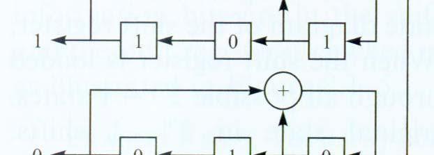
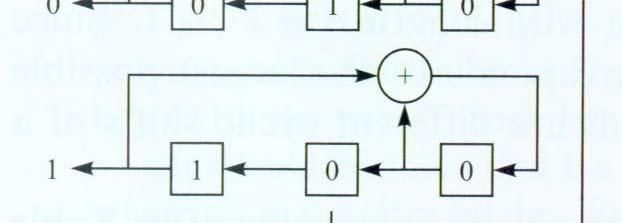
46 Pseudo-Noise Sequences In a direct-sequence spread spectrum system, each bit in the pseudorandom binary sequence is known as a chip and the inverse of its period as chip rate. Compare bit rate and baud. In a frequency-hopping spread spectrum sequence, each value in the pseudorandom sequence is known as a channel number and the inverse of its period as the hop rate. FCC Part 15 mandates at least 50 different channels and at least a 2.5 Hz hop rate for narrowband frequency-hopping systems. A pseudonoise code (PN code) is one that has a spectrum similar to a random sequence of bits but is deterministically generated. The most commonly used sequences in direct-sequence spread spectrum systems are maximal length sequences, Gold codes, Kasami codes, and dbarker codes. 46
47 Pseudo-Noise Sequences A pseudo-noise (PN) sequence is a periodic binary sequence with a noiselike waveform that is usually generated by means of a feedback shift register. 47
48 Pseudo-Noise Sequences A feedback shift register consists of an ordinary shift register made up of m flip-flop (two-state memory stages) and a logic circuit that are interconnected to form a feedback circuit. With a total number of m flip-flops, the number of possible state of the shift register is at most 2 m. A feedback shift register is said to be linear when the feedback logic consists entirely of modulo-2 adders. The all-zero state is not permitted. As a result, the period of a PN sequence produced by a linear feedback shift register with m flip-flops can t exceed 2 m -1. When the period is exactly 2 m -1, the PN sequence is called a maximal-length-sequence l or simply m-sequence. ence 48
49 Properties of Maximal-Length Sequences Balance property: In each period of a maximal-length sequence, the number of 1s is always one more than the number of 0s. Shift-and Add Property: The modulo-2 sum of an m- sequence and any phase shift of fthe same sequence is another phase of the same m-sequence. If a window of width m is slid along the sequence for N shifts, each m-tuple except the all zero m-tuple will appear exactly once. 49
50 Properties of Maximal-Length Sequences Run Property: By a run, we mean a subsequence of identical symbols (1s or 0s) within one period of the sequence. Among the runs of 1s and of 0s in each period of a maximal-length sequence, one-half the runs of each kind are of length one, one-fourth are of length two, one-eighth are of length three, and so on as long as these fractions represent meaningful numbers of runs. Autocorrelation ti property: the autocorrelation ti function of a maximum-length sequence is periodic and binary-valued. 50
51 Properties of Maximal-Length Sequences Convert 0 1 and 1-1. Let c(t) ( ) denote the resulting waveform of the maximal-length sequence. The period of the waveform c(t) is: T b =NT c, where T c is the duration assigned to symbol 1 or 0 and N=2 m -1. The autocorrelation function of a periodic signal c(t) of period T b is: 1 Tb /2 Rc ( τ) = c() t c( t τ) dt T T b /2 b 51
52 Properties of Maximal-Length Sequences The autocorrelation function of the maximal-length sequence is: R c τ = ( ) N + 1 τ NT 1 τ Tc c 1 N otherwise 52
53 Properties of Maximal-Length Sequences Periodicity in the time domain is transformed into uniform sampling in the frequency domain N 2 n n S ( ) = δ ( ) + c f f sinc δ f 2 2 N N n= N NTc n 0 53
54 Example of Maximum-Length Shift- Register Codes Systematic Code 54
55 Maximum-Length Shift Register 55
56 Maximal Length Shift Register (m=5) 56
57 Maximal Length Shift Register (m=5) 57
58 Maximal-Length Sequences of Shift- Register Lengths (2-8) 58
59 Maximal-Length Sequences of Shift- Register Lengths (2-34) Maximum-length shift-register codes exist for any positive value of m. 59
60 Problems with m-sequencem Problems 1: jammer can determine the feedback connections by observing only 2m-1 chips from the PN sequence. Solution 1: Output sequences from several stages of the shift register or the outputs from several distinct m-sequences are combined in a nonlinear sequence that is considerably more difficult for the jammer to learn. Solution 2: Frequently changing the feedback connections and/or the number of stages in the shift registers. 60
61 Problems with m-sequencem Problem 2: periodic cross correlation function between any pair of m-sequences of the same period can have relatively large peaks. Although it is possible to select a small subset of m sequences that have relatively smaller cross correlation peak values, the number of sequences in the set is usually too small for CDMA applications. 61

62 Correlation Properties of PN sequences Consider two PN sequences of period 2 7-1=127, one feedback shift register has the feedback taps [7,1] and the other one has the feedback taps [7,6,5,4]. Both sequences have the same autocorrelation ti function. 62
63 Peak Cross Correlation of m Sequences and Gold Sequences 63
64 Gold s theorem: Preferred Sequences Gold and Kasami proved that certain pairs of m sequences of length n (e.g. g 1 (X) and g 2 (X) ) exhibit a three-valued cross correlation function with values { -1, -t(m), t(m)-2} where: tm ( ) ( m+ 1)/ odd m = ( m+ 2)/ even m Two m sequences of length n with a periodic cross correlation function that takes on the possible values { -1, - t(m), t(m)-2} are called preferred sequences. The shift register corresponding to the product polynomial l g 1 (X) g 2 (X) will generate 2 m +1 different sequences, with each sequence having a period of 2 m
65 Golden Sequences From a pair of preferred sequences, say a=[ a 1 a 2 a 3 a n ] and b=[ b 1 b 2 b 3 b n ], we construct a set of sequences of length n by taking the modulo-2 sum of a with the n cyclicly shifted versions of b or vice versa. Thus, we obtain n new periodic sequences with period n=2 m -1. Together with the original sequences a and b, we have a total of n+2 sequences, which are called Gold sequences. With the exception of the sequences a and b, the set of Gold sequences is not comprised of maximum-length shift-register sequences of length n. The cross correlation function for any pair of sequences from the set of n+2 Gold sequences is three-valued with possible values { -1, -t(m), t(m)-2}. The off-peak autocorrelation function for a Gold sequence takes on values from the set { -1, -t(m), t(m)-2}. 65
66 Generator for a Gold Sequence of Period


67 Cross-Correlation Correlation Function Cross-correlation Cossco o function of a pair of Gold sequences based on the two PN sequences [7,4] and [7,6,5,4]. 67
68 Wireless Information Transmission System Lab. RAKE Receiver Institute of Communications Engineering National Sun Yat-sen University
69 Table of Contents Architecture of RAKE Receiver Combining Schemes Multipath th Searcher (Acquisition iti or Delay Estimation) RAKE Finger Management 69
70 Wireless Information Transmission System Lab. Architecture of RAKE Receiver Institute of Communications Engineering National Sun Yat-sen University
71 Architecture of RAKE Receiver Despread RAKE Finger (L) Channel Estimation Despread RAKE Finger (2) Delay G* i Σ Despread RAKE Finger (1) MRC 71
72 General Block Diagram of the Receiver The receiver is built up of four blocks: sub-chip tracking, multipath searcher and rake finger manager, the rake receiver and the decoder. Transmitter Channel Multi-path Searcher and Rake Finger Manager RF Match Sub-chip Time Rake Channel Filter Tracking Receiver Decoder 72
73 Wireless Information Transmission System Lab. Combining Schemes Institute of Communications Engineering National Sun Yat-sen University
74 Maximum Ratio Combining (MRC) To utilize the advantages of diversity techniques, channel parameters are necessary to be estimated. Arrival time of each path, Amplitude, and Phase. Maximal Ratio Combiner (MRC): The combiner that achieves the best performance is one in which each output is multiplied by the corresponding complex-valued (conjugate) channel gain. The effect of this multiplication is to compensate for the phase shift in the channel and to weight the signal by a factor that is proportional to the signal strength. 74
75 Maximum Ratio Combining (MRC) MRC: G i =A i e -jθ i Coherent Combining G 1 G 2 G L Channel Estimation Best Performance Receiver 75
76 Maximum Ratio Combining (MRC) L l= 1 L 2 2 = G 2, l= 1 L 2 Received Envelope: r = L G l r l Total lnoise Power: σn Gl σ n l SNR: SNR Since L 2 rl = = 2 σ 2 n 2 l= 1 L l= 1 G l G l r l 2 2 σ n, l L 2 L r l l l l n, l l= 1 l= 1 σ nl, G r = Gσ 76 2
77 Maximum Ratio Combining (MRC) Chebychev's Inequality: L 2 L L 2 rl Gl rl Glσ n, l l= 1 l= 1 l= 1 σ n, l 2 L 2 L L 2 r l Glσ n, l 2 L L 1 l= 1 l= 1 σ n, l 1 rl = L l= 1 σ n, l l= 1 G l σ n, l l= 1 SNR = With equality hold : G σ n, l Output SNR = Sum of l r = k σ * l n, l SNR SNRs from all G l l r * l 77
78 Equal Gain Combining The equal gain combining only compensates the channel phase shift. The gain for the EGC is given by Gi = j i e θ Thus, EGC is simpler to implement than MRC. Moreover, no channel amplitude estimation is needed.
79 Orthogonality Restoring Combining (ORC) The orthogonality restoring combining compensates the channel phase shift and the channel amplitude fading. The gain for the ORC is given by G i = 1 j i e θ i However, low level subcarriers tend to be multiplied by high gains, and the noise components are amplified at weaker subcarriers. The noise amplification effect degradesd the BER performance. j i h i = Ae θ i hi is the ith subchannel's channel response Ai is the magitude of hi θ is the phase of i hi A
80 Wireless Information Transmission System Lab. Multipath Searcher (Acquisition iti or Delay Estimation) Institute of Communications Engineering National Sun Yat-sen University
81 Multipath Searcher for Acquisition To maximize the sensitivity of the base station, the energy from all of the paths is combined to form an aggregate signal. Since the receiver has no a-priori knowledge of the possible paths, it must continuously search through h all the possible paths. Multi-path searcher searches and detects the multi-paths from the transmitter. These signals once detected, and selected (via the RAKE finger manager), are combined within the RAKE receiver. Typically, acquisition determines the timing offset to within ±1/2n for a over-sampling rate of n. The fine timing correction is achieved through the sub-chip timing tracker. 81
82 Searcher Architecture The mechanism of multipath searching is based on correlating the incoming i data samples with a locally ll generated code sequence. The correlation results indicate the potential multipath locations. There are two approaches for implementing the searcher: sliding correlator or matched filter. Bother approaches perform the same function. Typically, since approximate propagation delay has been estimated t before this stage, searcher can concentrate t its efforts on the multipath delay spread of the channel. As a result, a serial and parallel matched filter architecture can be adopted. However, in certain systems, the approximate propagation delay may not be known by the receiver. Under such situation, the search has to obtain the coarse synchronization. 82
83 Wireless Information Transmission System Lab. RAKE Finger Management Institute of Communications Engineering National Sun Yat-sen University
84 Introduction to RAKE Finger Management The multipath searcher tries to detect the valid multipaths and results are further processed by the RAKE finger manager to validate and keep track the multipaths during transmission. The performance of a multipath searcher can be evaluated in terms of detection probability and false alarm. However, the cost of error is unbalanced. The function of RAKE finger management, which performs by the RAKE finger manager (RFM), is to minimize the cost due to errors. Certain reports show that the cost of erroneous addition of an improper multi-path due to false alarm is higher than missing a correct multi-path. 84
85 Multipath Verification Processes When the searcher has found a set of multipath candidates, these potential fingers have to be further processed to confirm their validity. Typically, this consists of two major steps: The multipath confirmation process will be done by the RAKE finger manager. This process is typically implemented by the multipath verification function, which utilizes the information from both the searcher outputs and the channel estimation to assign a RAKE finger to a multipath. In addition, the finger tracking function uses the output of each RAKE finger s (fast) channel estimation to validate the existence of fingers and decides to drop/add or replace fingers. 85
86 Status of RAKE Fingers According to the multipath verification procedures, there are three states that a finger in a RAKE receiver can be designated: Inactive or idle finger: Finger that is not being used. Candidate finger: Finger that is under monitoring after being assigned by RAKE finger manager to work on a new multipath peak. This finger is not being used din MRC. Active finger: Finger which his used din MRC. 86
Spread Spectrum Signal for Digital Communications
 Wireless Information Transmission System Lab. Spread Spectrum Signal for Digital Communications Institute of Communications Engineering National Sun Yat-sen University Multiple Access Schemes Table of
Spread Spectrum Signal for Digital Communications
 Spread Spectrum Signal for Digital Communications Multiple Access Schemes Table of Contents Spread Spectrum Communications Generation of Pseudo-Noise (PN) Sequences Elementary Codes in WCDMA Multiple Access
Spread Spectrum Techniques
 0 Spread Spectrum Techniques Contents 1 1. Overview 2. Pseudonoise Sequences 3. Direct Sequence Spread Spectrum Systems 4. Frequency Hopping Systems 5. Synchronization 6. Applications 2 1. Overview Basic
Spread Spectrum. Chapter 18. FHSS Frequency Hopping Spread Spectrum DSSS Direct Sequence Spread Spectrum DSSS using CDMA Code Division Multiple Access
 Spread Spectrum Chapter 18 FHSS Frequency Hopping Spread Spectrum DSSS Direct Sequence Spread Spectrum DSSS using CDMA Code Division Multiple Access Single Carrier The traditional way Transmitted signal
ECS455: Chapter 4 Multiple Access
 ECS455: Chapter 4 Multiple Access 4.4 DS/SS 1 Dr.Prapun Suksompong prapun.com/ecs455 Office Hours: BKD 3601-7 Wednesday 15:30-16:30 Friday 9:30-10:30 Spread spectrum (SS) Historically spread spectrum was
Spread Spectrum: Definition
 Spread Spectrum: Definition refers to the expansion of signal bandwidth, by several orders of magnitude in some cases, which occurs when a key is attached to the communication channel an RF communications
Lecture 9: Spread Spectrum Modulation Techniques
 Lecture 9: Spread Spectrum Modulation Techniques Spread spectrum (SS) modulation techniques employ a transmission bandwidth which is several orders of magnitude greater than the minimum required bandwidth
CHAPTER 2. Instructor: Mr. Abhijit Parmar Course: Mobile Computing and Wireless Communication ( )
") CHAPTER 2 Instructor: Mr. Abhijit Parmar Course: Mobile Computing and Wireless Communication (2170710) Syllabus Chapter-2.4 Spread Spectrum Spread Spectrum SS was developed initially for military and intelligence
CHAPTER 2 Instructor: Mr. Abhijit Parmar Course: Mobile Computing and Wireless Communication (2170710) Syllabus Chapter-2.4 Spread Spectrum Spread Spectrum SS was developed initially for military and intelligence
Code Division Multiple Access.
 Code Division Multiple Access Mobile telephony, using the concept of cellular architecture, are built based on GSM (Global System for Mobile communication) and IS-95(Intermediate Standard-95). CDMA allows
Multi-Carrier Systems
 Wireless Information Transmission System Lab. Multi-Carrier Systems 2006/3/9 王森弘 Institute of Communications Engineering National Sun Yat-sen University Outline Multi-Carrier Systems Overview Multi-Carrier
Spread Spectrum Basics Spreading Codes IS-95 Features- Transmitter/Receiver Power Control Diversity Techniques RAKE Receiver Soft Handoff
 CDMA Mobile Communication & IS-95 1 Outline Spread Spectrum Basics Spreading Codes IS-95 Features- Transmitter/Receiver Power Control Diversity Techniques RAKE Receiver Soft Handoff 2 Spread Spectrum A
Multiple Access Techniques for Wireless Communications
 Multiple Access Techniques for Wireless Communications Contents 1. Frequency Division Multiple Access (FDMA) 2. Time Division Multiple Access (TDMA) 3. Code Division Multiple Access (CDMA) 4. Space Division
Chapter 7 Multiple Division Techniques for Traffic Channels
 Introduction to Wireless & Mobile Systems Chapter 7 Multiple Division Techniques for Traffic Channels Outline Introduction Concepts and Models for Multiple Divisions Frequency Division Multiple Access
UNIT 4 Spread Spectrum and Multiple. Access Technique
 UNIT 4 Spread Spectrum and Multiple Access Technique Spread Spectrum lspread spectrumis a communication technique that spreads a narrowband communication signal over a wide range of frequencies for transmission
Performance Analysis of DSSS and FHSS Techniques over AWGN Channel
 Performance Analysis of DSSS and FHSS Techniques over AWGN Channel M. Katta Swamy, M.Deepthi, V.Mounika, R.N.Saranya Vignana Bharathi Institute of Technology, Hyderabad, and Andhra Pradesh, India. Corresponding
Cross Spectral Density Analysis for Various Codes Suitable for Spread Spectrum under AWGN conditions with Error Detecting Code
 Cross Spectral Density Analysis for Various Codes Suitable for Spread Spectrum under AWG conditions with Error Detecting Code CH.ISHATHI 1, R.SUDAR RAJA 2 Department of Electronics and Communication Engineering,
ECS455: Chapter 4 Multiple Access
 ECS455: Chapter 4 Multiple Access 4.4 DS/SS 1 Dr.Prapun Suksompong prapun.com/ecs455 Office Hours: BKD 3601-7 Tuesday 9:30-10:30 Tuesday 13:30-14:30 Thursday 13:30-14:30 Spread spectrum (SS) Historically
CDMA Mobile Radio Networks
 - 1 - CDMA Mobile Radio Networks Elvino S. Sousa Department of Electrical and Computer Engineering University of Toronto Canada ECE1543S - Spring 1999 - 2 - CONTENTS Basic principle of direct sequence
Part 3. Multiple Access Methods. p. 1 ELEC6040 Mobile Radio Communications, Dept. of E.E.E., HKU
 Part 3. Multiple Access Methods p. 1 ELEC6040 Mobile Radio Communications, Dept. of E.E.E., HKU Review of Multiple Access Methods Aim of multiple access To simultaneously support communications between
Wireless Transmission & Media Access
 Wireless Transmission & Media Access Signals and Signal Propagation Multiplexing Modulation Media Access 1 Significant parts of slides are based on original material by Prof. Dr.-Ing. Jochen Schiller,
SC - Single carrier systems One carrier carries data stream
 Digital modulation SC - Single carrier systems One carrier carries data stream MC - Multi-carrier systems Many carriers are used for data transmission. Data stream is divided into sub-streams and each
Wireless Communication: Concepts, Techniques, and Models. Hongwei Zhang
 Wireless Communication: Concepts, Techniques, and Models Hongwei Zhang http://www.cs.wayne.edu/~hzhang Outline Digital communication over radio channels Channel capacity MIMO: diversity and parallel channels
Multiple Access Schemes
 Multiple Access Schemes Dr Yousef Dama Faculty of Engineering and Information Technology An-Najah National University 2016-2017 Why Multiple access schemes Multiple access schemes are used to allow many
Mobile & Wireless Networking. Lecture 2: Wireless Transmission (2/2)
") 192620010 Mobile & Wireless Networking Lecture 2: Wireless Transmission (2/2) [Schiller, Section 2.6 & 2.7] [Reader Part 1: OFDM: An architecture for the fourth generation] Geert Heijenk Outline of Lecture
192620010 Mobile & Wireless Networking Lecture 2: Wireless Transmission (2/2) [Schiller, Section 2.6 & 2.7] [Reader Part 1: OFDM: An architecture for the fourth generation] Geert Heijenk Outline of Lecture
SPREADING CODES PERFORMANCE FOR CORRELATION FUNCTION USING MATLAB
 International Journal of Electronics, Communication & Instrumentation Engineering Research and Development (IJECIERD) ISSN 2249-684X Vol. 3, Issue 2, Jun 2013, 15-24 TJPRC Pvt. Ltd. SPREADING CODES PERFORMANCE
UNIK4230: Mobile Communications. Abul Kaosher
 UNIK4230: Mobile Communications Abul Kaosher abul.kaosher@nsn.com Multiple Access Multiple Access Introduction FDMA (Frequency Division Multiple Access) TDMA (Time Division Multiple Access) CDMA (Code
Chapter 2 Direct-Sequence Systems
 Chapter 2 Direct-Sequence Systems A spread-spectrum signal is one with an extra modulation that expands the signal bandwidth greatly beyond what is required by the underlying coded-data modulation. Spread-spectrum
Physical Layer: Modulation, FEC. Wireless Networks: Guevara Noubir. S2001, COM3525 Wireless Networks Lecture 3, 1
 Wireless Networks: Physical Layer: Modulation, FEC Guevara Noubir Noubir@ccsneuedu S, COM355 Wireless Networks Lecture 3, Lecture focus Modulation techniques Bit Error Rate Reducing the BER Forward Error
Initial Synchronization
 Wireless Information Transmission System Lab. Initial Synchronization Institute of Communications Engineering National Sun Yat-sen University Contents Introduction and Over-sampling Downlink Synchronization
Multiplexing Module W.tra.2
 Multiplexing Module W.tra.2 Dr.M.Y.Wu@CSE Shanghai Jiaotong University Shanghai, China Dr.W.Shu@ECE University of New Mexico Albuquerque, NM, USA 1 Multiplexing W.tra.2-2 Multiplexing shared medium at
Part A: Spread Spectrum Systems
 1 Telecommunication Systems and Applications (TL - 424) Part A: Spread Spectrum Systems Dr. ir. Muhammad Nasir KHAN Department of Electrical Engineering Swedish College of Engineering and Technology March
Mobile Communications TCS 455
 Mobile Communications TCS 455 Dr. Prapun Suksompong prapun@siit.tu.ac.th Lecture 21 1 Office Hours: BKD 3601-7 Tuesday 14:00-16:00 Thursday 9:30-11:30 Announcements Read Chapter 9: 9.1 9.5 HW5 is posted.
Spread Spectrum (SS) is a means of transmission in which the signal occupies a
 is a means of transmission in which the signal occupies a") SPREAD-SPECTRUM SPECTRUM TECHNIQUES: A BRIEF OVERVIEW SS: AN OVERVIEW Spread Spectrum (SS) is a means of transmission in which the signal occupies a bandwidth in excess of the minimum necessary to send
SPREAD-SPECTRUM SPECTRUM TECHNIQUES: A BRIEF OVERVIEW SS: AN OVERVIEW Spread Spectrum (SS) is a means of transmission in which the signal occupies a bandwidth in excess of the minimum necessary to send
GNSS Technologies. GNSS Acquisition Dr. Zahidul Bhuiyan Finnish Geospatial Research Institute, National Land Survey
 GNSS Acquisition 25.1.2016 Dr. Zahidul Bhuiyan Finnish Geospatial Research Institute, National Land Survey Content GNSS signal background Binary phase shift keying (BPSK) modulation Binary offset carrier
Unit 1 Introduction to Spread- Spectrum Systems. Department of Communication Engineering, NCTU 1
 Unit 1 Introduction to Spread- Spectrum Systems Department of Communication Engineering, NCTU 1 What does it mean by spread spectrum communications Spread the energy of an information bit over a bandwidth
Multiple Access Techniques
 Multiple Access Techniques EE 442 Spring Semester Lecture 13 Multiple Access is the use of multiplexing techniques to provide communication service to multiple users over a single channel. It allows for
Laboratory 5: Spread Spectrum Communications
 Laboratory 5: Spread Spectrum Communications Cory J. Prust, Ph.D. Electrical Engineering and Computer Science Department Milwaukee School of Engineering Last Update: 19 September 2018 Contents 0 Laboratory
ALi Linear n-stage t ShiftRegister output tsequence
 PN CODE GENERATION (cont d) ALi Linear n-stage t ShiftRegister output tsequence Modulo-2 Adder h hn-1 h hn-2 h h2 h h1 X n-1 X n-2 X 1 X 0 Output Note: hi=1 represents a closed circuit; hi=0 represents
SPREAD SPECTRUM (SS) SIGNALS FOR DIGITAL COMMUNICATIONS
 SIGNALS FOR DIGITAL COMMUNICATIONS") Dr. Ali Muqaibel SPREAD SPECTRUM (SS) SIGNALS FOR DIGITAL COMMUNICATIONS VERSION 1.1 Dr. Ali Hussein Muqaibel 1 Introduction Narrow band signal (data) In Spread Spectrum, the bandwidth W is much greater
Dr. Ali Muqaibel SPREAD SPECTRUM (SS) SIGNALS FOR DIGITAL COMMUNICATIONS VERSION 1.1 Dr. Ali Hussein Muqaibel 1 Introduction Narrow band signal (data) In Spread Spectrum, the bandwidth W is much greater
Chapter 7 Spread-Spectrum Modulation
 Chapter 7 Spread-Spectrum Modulation Spread Spectrum Technique simply consumes spectrum in excess of the minimum spectrum necessary to send the data. 7.1 Introduction o Definition of spread-spectrum modulation
Multiple Access Techniques
 Multiple Access Techniques Instructor: Prof. Dr. Noor M. Khan Department of Electrical Engineering, Faculty of Engineering, Mohammad Ali Jinnah University, Islamabad Campus, Islamabad, PAKISTAN Ph: +92
Chapter 7 Spread-Spectrum Modulation
 Chapter 7 Spread-Spectrum Modulation Spread Spectrum Technique simply consumes spectrum in excess of the minimum spectrum necessary to send the data. 7.1 Introduction Definition of spread-spectrum modulation
CHAPTER 6 SPREAD SPECTRUM. Xijun Wang
 CHAPTER 6 SPREAD SPECTRUM Xijun Wang WEEKLY READING 1. Goldsmith, Wireless Communications, Chapters 13 2. Tse, Fundamentals of Wireless Communication, Chapter 4 2 WHY SPREAD SPECTRUM n Increase signal
 DEPARTMENT OF COMPUTER GCE@Bodi_ SCIENCE GCE@Bodi_ AND ENIGNEERING GCE@Bodi_ GCE@Bodi_ GCE@Bodi_ Analog and Digital Communication GCE@Bodi_ DEPARTMENT OF CsE Subject Name: Analog and Digital Communication
Satellite Telemetry Data Transmission Immunity from the ASI and Jamming Using DSSS Optimized PN Codes in DS-CDMA Systems
 IOSR Journal of Electronics and Communication Engineering (IOSR-JECE) e-issn: 2278-2834,p- ISSN: 2278-8735.Volume 12, Issue 1, Ver. II (Jan.-Feb. 2017), PP 01-12 www.iosrjournals.org Satellite Telemetry
WCDMA Basics Chapter 2 OBJECTIVES:
 WCDMA Basics Chapter 2 This chapter is designed to give the students a brief review of the WCDMA basics of the WCDMA Experimental System. This is meant as a review only as the WCDMA basics have already
QUESTION BANK EC 1351 DIGITAL COMMUNICATION YEAR / SEM : III / VI UNIT I- PULSE MODULATION PART-A (2 Marks) 1. What is the purpose of sample and hold
 1. What is the purpose of sample and hold") QUESTION BANK EC 1351 DIGITAL COMMUNICATION YEAR / SEM : III / VI UNIT I- PULSE MODULATION PART-A (2 Marks) 1. What is the purpose of sample and hold circuit 2. What is the difference between natural sampling
QUESTION BANK EC 1351 DIGITAL COMMUNICATION YEAR / SEM : III / VI UNIT I- PULSE MODULATION PART-A (2 Marks) 1. What is the purpose of sample and hold circuit 2. What is the difference between natural sampling
Part A: Spread Spectrum Systems
 1 Telecommunication Systems and Applications (TL - 424) Part A: Spread Spectrum Systems Dr. ir. Muhammad Nasir KHAN Department of Electrical Engineering Swedish College of Engineering and Technology February
Chapter 7. Multiple Division Techniques
 Chapter 7 Multiple Division Techniques 1 Outline Frequency Division Multiple Access (FDMA) Division Multiple Access (TDMA) Code Division Multiple Access (CDMA) Comparison of FDMA, TDMA, and CDMA Walsh
Noise Effective Code Analysis on the Basis of Correlation in CDMA Technology
 Manarat International University Studies, 2 (1): 183-191, December 2011 ISSN 1815-6754 @ Manarat International University, 2011 Noise Effective Code Analysis on the Basis of Correlation in CDMA Technology
EFFICIENT SMART ANTENNA FOR 4G COMMUNICATIONS
 http:// EFFICIENT SMART ANTENNA FOR 4G COMMUNICATIONS 1 Saloni Aggarwal, 2 Neha Kaushik, 3 Deeksha Sharma 1,2,3 UG, Department of Electronics and Communication Engineering, Raj Kumar Goel Institute of
CDMA - QUESTIONS & ANSWERS
 CDMA - QUESTIONS & ANSWERS http://www.tutorialspoint.com/cdma/questions_and_answers.htm Copyright tutorialspoint.com 1. What is CDMA? CDMA stands for Code Division Multiple Access. It is a wireless technology
Diversity. Spring 2017 ELE 492 FUNDAMENTALS OF WIRELESS COMMUNICATIONS 1
 Diversity Spring 2017 ELE 492 FUNDAMENTALS OF WIRELESS COMMUNICATIONS 1 Diversity A fading channel with an average SNR has worse BER performance as compared to that of an AWGN channel with the same SNR!.
Wireless Networks (PHY): Design for Diversity
: Design for Diversity") Wireless Networks (PHY): Design for Diversity Y. Richard Yang 9/20/2012 Outline Admin and recap Design for diversity 2 Admin Assignment 1 questions Assignment 1 office hours Thursday 3-4 @ AKW 307A 3 Recap:
Wireless Networks (PHY): Design for Diversity Y. Richard Yang 9/20/2012 Outline Admin and recap Design for diversity 2 Admin Assignment 1 questions Assignment 1 office hours Thursday 3-4 @ AKW 307A 3 Recap:
KINGS COLLEGE OF ENGINEERING DEPARTMENT OF ELECTRONICS AND COMMUNICATION ENGINEERING QUESTION BANK. Subject Name: Digital Communication Techniques
 KINGS COLLEGE OF ENGINEERING DEPARTMENT OF ELECTRONICS AND COMMUNICATION ENGINEERING QUESTION BANK Subject Code: EC1351 Year/Sem: III/IV Subject Name: Digital Communication Techniques UNIT I PULSE MODULATION
Introduction to Wireless and Mobile Networking. Hung-Yu Wei g National Taiwan University
 Introduction to Wireless and Mobile Networking Lecture 3: Multiplexing, Multiple Access, and Frequency Reuse Hung-Yu Wei g National Taiwan University Multiplexing/Multiple Access Multiplexing Multiplexing
Chapter 2: Wireless Transmission. Mobile Communications. Spread spectrum. Multiplexing. Modulation. Frequencies. Antenna. Signals
 Mobile Communications Chapter 2: Wireless Transmission Frequencies Multiplexing Signals Spread spectrum Antenna Modulation Signal propagation Cellular systems Prof. Dr.-Ing. Jochen Schiller, http://www.jochenschiller.de/
Mobile and Personal Communications. Dr Mike Fitton, Telecommunications Research Lab Toshiba Research Europe Limited
 Mobile and Personal Communications Dr Mike Fitton, mike.fitton@toshiba-trel.com Telecommunications Research Lab Toshiba Research Europe Limited 1 Mobile and Personal Communications Outline of Lectures
Mobile Radio Propagation Channel Models
 Wireless Information Transmission System Lab. Mobile Radio Propagation Channel Models Institute of Communications Engineering National Sun Yat-sen University Table of Contents Introduction Propagation
ORTHOGONAL frequency division multiplexing (OFDM)
") 144 IEEE TRANSACTIONS ON BROADCASTING, VOL. 51, NO. 1, MARCH 2005 Performance Analysis for OFDM-CDMA With Joint Frequency-Time Spreading Kan Zheng, Student Member, IEEE, Guoyan Zeng, and Wenbo Wang, Member,
144 IEEE TRANSACTIONS ON BROADCASTING, VOL. 51, NO. 1, MARCH 2005 Performance Analysis for OFDM-CDMA With Joint Frequency-Time Spreading Kan Zheng, Student Member, IEEE, Guoyan Zeng, and Wenbo Wang, Member,
Orthogonal Cyclic Prefix for Time Synchronization in MIMO-OFDM
 Orthogonal Cyclic Prefix for Time Synchronization in MIMO-OFDM Gajanan R. Gaurshetti & Sanjay V. Khobragade Dr. Babasaheb Ambedkar Technological University, Lonere E-mail : gaurshetty@gmail.com, svk2305@gmail.com
Multi-Path Fading Channel
 Instructor: Prof. Dr. Noor M. Khan Department of Electronic Engineering, Muhammad Ali Jinnah University, Islamabad Campus, Islamabad, PAKISTAN Ph: +9 (51) 111-878787, Ext. 19 (Office), 186 (Lab) Fax: +9
S.D.M COLLEGE OF ENGINEERING AND TECHNOLOGY
 VISHVESHWARAIAH TECHNOLOGICAL UNIVERSITY S.D.M COLLEGE OF ENGINEERING AND TECHNOLOGY A seminar report on Orthogonal Frequency Division Multiplexing (OFDM) Submitted by Sandeep Katakol 2SD06CS085 8th semester
Level 6 Graduate Diploma in Engineering Wireless and mobile communications
 9210-119 Level 6 Graduate Diploma in Engineering Wireless and mobile communications Sample Paper You should have the following for this examination one answer book non-programmable calculator pen, pencil,
Chapter 2: Signal Representation
 Chapter 2: Signal Representation Aveek Dutta Assistant Professor Department of Electrical and Computer Engineering University at Albany Spring 2018 Images and equations adopted from: Digital Communications
EC 551 Telecommunication System Engineering. Mohamed Khedr
 EC 551 Telecommunication System Engineering Mohamed Khedr http://webmail.aast.edu/~khedr 1 Mohamed Khedr., 2008 Syllabus Tentatively Week 1 Week 2 Week 3 Week 4 Week 5 Week 6 Week 7 Week 8 Week 9 Week
Spread Spectrum Modulation
 Spread Spectrum Modulation A collective class of signaling techniques are employed before transmitting a signal to provide a secure communication, known as the Spread Spectrum Modulation. The main advantage
Smart antenna technology
 Smart antenna technology In mobile communication systems, capacity and performance are usually limited by two major impairments. They are multipath and co-channel interference [5]. Multipath is a condition
ISHIK UNIVERSITY Faculty of Science Department of Information Technology Fall Course Name: Wireless Networks
 ISHIK UNIVERSITY Faculty of Science Department of Information Technology 2017-2018 Fall Course Name: Wireless Networks Agenda Lecture 4 Multiple Access Techniques: FDMA, TDMA, SDMA and CDMA 1. Frequency
Lecture 13. Introduction to OFDM
 Lecture 13 Introduction to OFDM Ref: About-OFDM.pdf Orthogonal frequency division multiplexing (OFDM) is well-known to be effective against multipath distortion. It is a multicarrier communication scheme,
Amplitude Frequency Phase
 Chapter 4 (part 2) Digital Modulation Techniques Chapter 4 (part 2) Overview Digital Modulation techniques (part 2) Bandpass data transmission Amplitude Shift Keying (ASK) Phase Shift Keying (PSK) Frequency
Performance of Wideband Mobile Channel with Perfect Synchronism BPSK vs QPSK DS-CDMA
 Performance of Wideband Mobile Channel with Perfect Synchronism BPSK vs QPSK DS-CDMA By Hamed D. AlSharari College of Engineering, Aljouf University, Sakaka, Aljouf 2014, Kingdom of Saudi Arabia, hamed_100@hotmail.com
= = (1) Denote the noise signal in the i th branch as n i, assume without loss of generality that the noise is zero mean and unit variance. i.e.
 Denote the noise signal in the i th branch as n i, assume without loss of generality that the noise is zero mean and unit variance. i.e.") Performance of Diversity Schemes & Spread Spectrum Systems* 6:33:546 Wireless Communication echnologies, Spring 5 Department of Electrical Engineering, Rutgers University, Piscataway, NJ 894 Vivek Vadakkuppattu
Performance of Diversity Schemes & Spread Spectrum Systems* 6:33:546 Wireless Communication echnologies, Spring 5 Department of Electrical Engineering, Rutgers University, Piscataway, NJ 894 Vivek Vadakkuppattu
ECE 476/ECE 501C/CS Wireless Communication Systems Winter Lecture 9: Multiple Access, GSM, and IS-95
 ECE 476/ECE 501C/CS 513 - Wireless Communication Systems Winter 2003 Lecture 9: Multiple Access, GSM, and IS-95 Outline: Two other important issues related to multiple access space division with smart
Channel. Muhammad Ali Jinnah University, Islamabad Campus, Pakistan. Multi-Path Fading. Dr. Noor M Khan EE, MAJU
 Instructor: Prof. Dr. Noor M. Khan Department of Electronic Engineering, Muhammad Ali Jinnah University, Islamabad Campus, Islamabad, PAKISTAN Ph: +9 (51) 111-878787, Ext. 19 (Office), 186 (Lab) Fax: +9
CSC344 Wireless and Mobile Computing. Department of Computer Science COMSATS Institute of Information Technology
 CSC344 Wireless and Mobile Computing Department of Computer Science COMSATS Institute of Information Technology Wireless Physical Layer Concepts Part III Noise Error Detection and Correction Hamming Code
KINGS DEPARTMENT OF ELECTRONICS AND COMMUNICATION ENGINEERING DIGITAL COMMUNICATION TECHNIQUES YEAR/SEM: III / VI BRANCH : ECE PULSE MODULATION
 KINGS COLLEGE OF ENGINEERING DEPARTMENT OF ELECTRONICS AND COMMUNICATION ENGINEERING SUB.NAME : EC1351 DIGITAL COMMUNICATION TECHNIQUES BRANCH : ECE YEAR/SEM: III / VI UNIT I PULSE MODULATION PART A (2
Lecture 3 Cellular Systems
 Lecture 3 Cellular Systems I-Hsiang Wang ihwang@ntu.edu.tw 3/13, 2014 Cellular Systems: Additional Challenges So far: focus on point-to-point communication In a cellular system (network), additional issues
COMMUNICATION SYSTEMS
 COMMUNICATION SYSTEMS 4TH EDITION Simon Hayhin McMaster University JOHN WILEY & SONS, INC. Ш.! [ BACKGROUND AND PREVIEW 1. The Communication Process 1 2. Primary Communication Resources 3 3. Sources of
Lecture LTE (4G) -Technologies used in 4G and 5G. Spread Spectrum Communications
 -Technologies used in 4G and 5G. Spread Spectrum Communications") COMM 907: Spread Spectrum Communications Lecture 10 - LTE (4G) -Technologies used in 4G and 5G The Need for LTE Long Term Evolution (LTE) With the growth of mobile data and mobile users, it becomes essential
COMM 907: Spread Spectrum Communications Lecture 10 - LTE (4G) -Technologies used in 4G and 5G The Need for LTE Long Term Evolution (LTE) With the growth of mobile data and mobile users, it becomes essential
CDMA Principle and Measurement
 CDMA Principle and Measurement Concepts of CDMA CDMA Key Technologies CDMA Air Interface CDMA Measurement Basic Agilent Restricted Page 1 Cellular Access Methods Power Time Power Time FDMA Frequency Power
Spread Spectrum Communications and Jamming Prof. Kutty Shajahan M G S Sanyal School of Telecommunications Indian Institute of Technology, Kharagpur
 Spread Spectrum Communications and Jamming Prof. Kutty Shajahan M G S Sanyal School of Telecommunications Indian Institute of Technology, Kharagpur Lecture - 06 Tutorial I Hello friends, welcome to this
Lecture 3: Wireless Physical Layer: Modulation Techniques. Mythili Vutukuru CS 653 Spring 2014 Jan 13, Monday
 Lecture 3: Wireless Physical Layer: Modulation Techniques Mythili Vutukuru CS 653 Spring 2014 Jan 13, Monday Modulation We saw a simple example of amplitude modulation in the last lecture Modulation how
ECS455: Chapter 4 Multiple Access
 ECS455: Chapter 4 Multiple Access 4.9 Async. CDMA: Gold codes and GPS 1 Dr.Prapun Suksompong prapun.com/ecs455 Office Hours: BKD 3601-7 Tuesday 9:30-10:30 Tuesday 13:30-14:30 Thursday 13:30-14:30 Asynchronous
6 Uplink is from the mobile to the base station.
 It is well known that by using the directional properties of adaptive arrays, the interference from multiple users operating on the same channel as the desired user in a time division multiple access (TDMA)
Spread Spectrum Communications and Jamming Prof. Debarati Sen G S Sanyal School of Telecommunications Indian Institute of Technology, Kharagpur
 Spread Spectrum Communications and Jamming Prof. Debarati Sen G S Sanyal School of Telecommunications Indian Institute of Technology, Kharagpur Lecture 07 Slow and Fast Frequency Hopping Hello students,
Access Methods and Spectral Efficiency
 Access Methods and Spectral Efficiency Yousef Dama An-Najah National University Mobile Communications Access methods SDMA/FDMA/TDMA SDMA (Space Division Multiple Access) segment space into sectors, use
Satellite Navigation Principle and performance of GPS receivers
 Satellite Navigation Principle and performance of GPS receivers AE4E08 GPS Block IIF satellite Boeing North America Christian Tiberius Course 2010 2011, lecture 3 Today s topics Introduction basic idea
Cognitive Radio Transmission Based on Chip-level Space Time Block Coded MC-DS-CDMA over Fast-Fading Channel
 Journal of Scientific & Industrial Research Vol. 73, July 2014, pp. 443-447 Cognitive Radio Transmission Based on Chip-level Space Time Block Coded MC-DS-CDMA over Fast-Fading Channel S. Mohandass * and
EECS 380: Wireless Technologies Week 7-8
 EECS 380: Wireless Technologies Week 7-8 Michael L. Honig Northwestern University May 2018 Outline Diversity, MIMO Multiple Access techniques FDMA, TDMA OFDMA (LTE) CDMA (3G, 802.11b, Bluetooth) Random
2. TELECOMMUNICATIONS BASICS
 2. TELECOMMUNICATIONS BASICS The purpose of any telecommunications system is to transfer information from the sender to the receiver by a means of a communication channel. The information is carried by
ECE 5325/6325: Wireless Communication Systems Lecture Notes, Spring 2013
 ECE 5325/6325: Wireless Communication Systems Lecture Notes, Spring 2013 Lecture 17 Today: Spread Spectrum: (1) Frequency Hopping, (2) Direct Sequence Reading: Today Molisch 18.1, 18.2. Thu: MUSE Channel
Chapter 2 Overview - 1 -
 Chapter 2 Overview Part 1 (last week) Digital Transmission System Frequencies, Spectrum Allocation Radio Propagation and Radio Channels Part 2 (today) Modulation, Coding, Error Correction Part 3 (next
Fundamentals of spread-spectrum techniques
 Fundamentals of spread-spectrum techniques 3 In this chapter we consider the spread-spectrum transmission schemes that demand channel bandwidth much greater than is required by the Nyquist sampling theorem.
Diversity Techniques
 Diversity Techniques Vasileios Papoutsis Wireless Telecommunication Laboratory Department of Electrical and Computer Engineering University of Patras Patras, Greece No.1 Outline Introduction Diversity
Prof. P. Subbarao 1, Veeravalli Balaji 2
 Performance Analysis of Multicarrier DS-CDMA System Using BPSK Modulation Prof. P. Subbarao 1, Veeravalli Balaji 2 1 MSc (Engg), FIETE, MISTE, Department of ECE, S.R.K.R Engineering College, A.P, India
Fundamentals of Digital Communication
 Fundamentals of Digital Communication Network Infrastructures A.A. 2017/18 Digital communication system Analog Digital Input Signal Analog/ Digital Low Pass Filter Sampler Quantizer Source Encoder Channel
QUESTION BANK SUBJECT: DIGITAL COMMUNICATION (15EC61)
") QUESTION BANK SUBJECT: DIGITAL COMMUNICATION (15EC61) Module 1 1. Explain Digital communication system with a neat block diagram. 2. What are the differences between digital and analog communication systems?
QUESTION BANK SUBJECT: DIGITAL COMMUNICATION (15EC61) Module 1 1. Explain Digital communication system with a neat block diagram. 2. What are the differences between digital and analog communication systems?
Statistical Analysis and Reduction of Multiple Access Interference in MC-CDMA Systems
 Statistical Analysis and Reduction of Multiple Access Interference in MC-CDMA Systems Xuan Li Faculty of Built Environment and Engineering Queensland University of Technology A thesis submitted for the
CDMA Systems Engineering Handbook
 CDMA Systems Engineering Handbook Jhong Sam Lee Leonard E. Miller Artech House Boston London Table of Contents Preface xix CHAPTER 1: INTRODUCTION AND REVIEW OF SYSTEMS ANALYSIS BASICS 1 1.1 Introduction