Initial Synchronization
|
|
|
- Kristian Holmes
- 5 years ago
- Views:
Transcription
1 Wireless Information Transmission System Lab. Initial Synchronization Institute of Communications Engineering National Sun Yat-sen University
2 Contents Introduction and Over-sampling Downlink Synchronization -- Cell Search Correlator Parallel Matched Filter Detail considerations in designing cell search. Serial and Parallel Matched Filter Frequency Offset Coherent vs. Non-coherent Detection Implement of Square Root Circuit Noise Effect and Multi-path Signals. Uplink Synchronization -- PRACH Preamble Detection
3 Wireless Information Transmission System Lab. Introduction and Over-sampling Institute of Communications Engineering National Sun Yat-sen University
4 Initial Synchronization Downlink initial synchronization Initial Cell Search (power on) Capture the slot & frame timing of the chosen BS and establish links. Target Cell Search (handoff) To re-synchronize to a new BS. In WCDMA, there is no global synchronization between BSs. Uplink initial synchronization PRACH preamble code detection. 4
5 Sampling Theorem 5
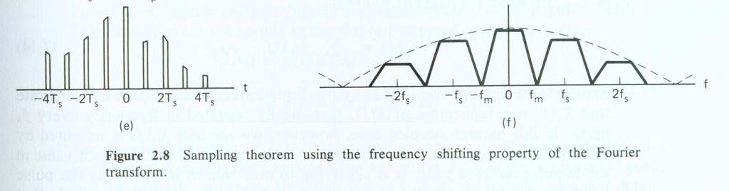
6 Sampling Theorem Sampling Theorem: A bandlimited signal having no spectral components above f m hertz can be determined uniquely by values sampled at uniform intervals of T s seconds, where TS or sampling rate f S f m f m In sample-and-hold operation, a switch and storage mechanism form a sequence of samples of the continuous input waveform. The output of the sampling process is called pulse amplitude modulation (PAM). 6

 X δ f")

7 Sampling Theorem X S ( f ) = X ( f ) X δ ( f ) = X ( f nfs ) T 7 S n=
8 Spectra for Various Sampling Rates 8

9 Natural Sampling 9
10 Initial Synchronization To establish initial synchronization between BS and MS. At the receiving end, there is often a over-sampling procedure, which takes several samples per chip. Depending on the over-sampling rate, the accuracy of initial synchronization is within ±/( over-sampling rate). Determination of over-sampling rate is a trade off between performance and hardware cost. Under most of the conditions, over-sampling rate is chosen among, 4, and 8. 0
11 Over-sampling of a sinc Function (I) Oversampling Rate = Max(Sample)= sinc T
12 Over-sampling of a sinc Function (II) Oversampling Rate = 4 Max(Sample)= sinc T
13 Over-sampling of a Raised Cosine (I) Oversampling Rate = ; Beta = 0.; Max(Sample)= raised cosine T 3
14 Over-sampling of a Raised Cosine (II) Oversampling Rate = 4; Beta = 0.; Max(Sample)= raised cosine T 4
15 Over-sampling of a Raised Cosine (III) raised cosine raised cosine OS Rate = ; Beta = 0.50; Max= T OS Rate = ; Beta =.00; Max= T raised cosine raised cosine OS Rate = 4; Beta = 0.50; Max= T OS Rate = 4; Beta =.00; Max= T 5
16 Wireless Information Transmission System Lab. Downlink Initial Synchronization Cell Search Institute of Communications Engineering National Sun Yat-sen University
17 Downlink Synchronization Base stations always transmit synchronization codes in synchronization channel - T c Synchronization code MS is synchronized to BS with the aid of synch. code In 3GPP, a synchronization code of 56 chips is used. 7
18 Structure of Synchronisation Channel (SCH) Secondary SCH ac s i,0 Slot #0 Slot # Slot #4 Primary SCH ac p ac p ac p 56 chips 560 chips ac s i, One 0 ms SCH radio frame ac s i,4 8
19 Cell Search Procedures During the cell search, the UE searches for a cell and determines the downlink scrambling code and frame synchronisation of that cell. The cell search is typically carried out in three steps:. Slot synchronization. Frame synchronization/code-group identification 3. Scrambling-code identification 9
20 Synchronization Channel and Common Pilot Channel for Cell Search First step of cell search uses primary synchronization (P-SCH). Second step of cell search uses secondary synchronization (S- SCH). Third step of cell search uses common pilot channel (CPICH). One Frame (0 ms) One Slot (0.67 ms, 560 chips) P-SCH 56 chips (0.067 ms) S-SCH CPICH 0
21 Slot Synchronization During the first step of the cell search procedure the UE uses the SCH s primary synchronisation code to acquire slot synchronisation to a cell. In 3GPP W-CDMA, Primary SCH is the same for every BS At each slot beginning, P-SCH codes of 56 are transmitted and then turned off until the next slot. A matched filter could be used to match the code such that the strongest path from a certain BS could be captured. Due to path propagation loss, the strongest path usually comes from the nearest BS.
22 Primary Synchronization Codes Primary SYN code (PSC), C psc Constructed as a so called generalised hierarchical Golay sequence. Good aperiodic auto-correlation properties. Define a = <x, x, x 3,, x 6 > = <,,,,,, -, -,, -,, -,, -, -, > PSC, C psc = ( + j) <a, a, a, -a, -a, a, -a, -a, a, a, a, -a, a, -a, a, a>, The leftmost chip in the sequence corresponds to the chip transmitted first in time
23 Wireless Information Transmission System Lab. Correlator Institute of Communications Engineering National Sun Yat-sen University
24 Structure of Correlator Correlator Correlation is done at chip rate. Received Signal cos(πft) carrier 90 o sin(πft) H*(f) S Sample a n (k) N ( ) n = H*(f) N ( ) n= Samples are taken at over-sampling rate. Read code coefficient at chip rate. Threshold Detection 4
25 Delay Line and Correlator Bank Local PN Code Over-sampling Rate. Delay Line Tc/ Tc/ 3 Tc/.... (N-) Tc/ Received Signals C (t) C (t-tc/) C (t-tc/) C (t-3tc/).... C (t-(n-)tc/) S.... Output i=0 i= i= i=3.... i=n- 5
26 Operation of Correlator Bank Example: Over-sampling rate :. Received signals after over-sampling: r, r, r, r, r, r,..., r, r,... etc. 3 3 PN code or Synchronization code: C, C, C 3,, C 56. Searching window : 560 chips. Note that, we need 560 =50 correlators for a oversampling rate of and searching window of 560 chips. If we consider both I and Q, the number of correlators is doubled. Of course, if hardware re-use is applied, number of correlators needed can be reduced. 6 i i
27 Operation of Correlator Bank Received signals after over-sampling Code Delay Tc Tc 0 C 56 C 56 C C C C 56 i= 56 i= c r + i c r + i i 0 i 0 Tc 59 Tc 58 C 56 C 56 C C C C 56 i= 56 i= c r + ci r i i 7 i 559
28 Wireless Information Transmission System Lab. Parallel Matched Filter Institute of Communications Engineering National Sun Yat-sen University
29 Structure of Parallel Matched Filter Tapped Delay Line Received Signals Output Code Coefficient 9
30 Example: Operation of Parallel Matched Filter Over-sampling rate :. Received signals after over-sampling: r, r, r, r, r, r,..., r, r,... etc. 3 3 i PN code or Synchronization code: C, C, C 3,, C 56. Searching window : 560 chips. i Note that we need only one matched filter of tap length 56 to search virtually infinite large time window. 30
31 Operation of Parallel Matched Filter Time = 0 Over-sampled signals r 56 r 56 r 55 r 55 r 3 r 3 r r r r C 56 C 55 C 3 C C Output 56 i= c r + i i 0 3
32 Operation of Parallel Matched Filter Time = Tc/ Over-sampled signals r 57 r 56 r 56 r 55 r 4 r 3 r 3 r r r C 56 C 55 C 3 C C Output 56 i= c r + i i 0 3
33 Operation of Parallel Matched Filter Time = 58 Tc/ Over-sampled signals r 85 r 85 r 84 r 84 r 56 r 56 r 56 r 56 r 560 r 560 C 56 C 55 C 3 C C Output 56 i= c r + i i
34 Operation of Parallel Matched Filter Time = 59 Tc/ Over-sampled signals r 86 r 85 r 85 r 84 r 563 r 56 r 56 r 56 r 56 r 560 C 56 C 55 C 3 C C Output 56 i= c r + i i
35 Operation of Parallel Matched Filter Received signals after over-sampling Time of output. Tc Tc 0 C 56 C 56 C C C C 56 i= 56 i= c r + i ci r i + 0 i 0 Tc 59 Tc 58 C 56 C 56 C C C C 56 i= 56 i= ci r i ci r i
36 Adder Tree of Matched Filter <5,4,t> m0 m m m3 m4 m5 m6 m7 m8 m9 ma mb mc md me mf <6,5,t> <7,6,t> <8,7,t> <9,8,t> 36
37 Correlator Bank vs. Parallel Matched Filter The number of correlators needed in a correlator bank is equal to the number of chips, which corresponds to the length of the search window, times the over-sampling rate. The length of the matched filter tapped delay line equals to both the accumulation time and the number of code chips. The matched filter needs much more registers, multipliers, and adders. Matched filter is adopted under most of the situations for coarse synchronization. 37
38 Wireless Information Transmission System Lab. Detail Considerations in Designing Cell Search Institute of Communications Engineering National Sun Yat-sen University
39 Problems with the st Stage Cell Search There are a few problems with the st stage cell search using matched filter: Matched filter usually occupies a large area in the IC. Serial and Parallel Matched Filter Frequency error due to low cost crystal oscillator (frequency offset). Coherent vs. non-coherent detection. Complexity of square root circuit. Noise effect and multi-path signals. 39
40 Serial and Parallel Matched Filter Received Signal tapped delay line Output Parallel Load 3 N N-chip digital delay PN code coefficient G.. J. R. Povey and P. M. Grant, Simplified matched filter receiver designs for spread spectrum communications applications, Electronics & Communication Engineering Journal, Apr
41 Serial and Parallel Matched Filter Example: Over-sampling rate :. Matched filter tap length : 3 (N=3). Received signals after over-sampling: r, r, r, r, r3, r3,..., ri, ri,... etc. PN code or Synchronization code: C, C, C 3,, C 56. Note that N=3 implies that we would like to search for a time window of 3 chips. We need to store the sampled data of 64 samples. We need a 3-chip digital delay registers (64 data). We need a matched filter of 3 taps in length. 4
42 Serial and Parallel Matched Filter Time = 0 Tc/ Received sample: - r 3 r 3 r 3 r 3 r r Length of matched filter times over-sampling rate. 3 X 3 ci r i i= C 3 C 3 C 4
43 Serial and Parallel Matched Filter Received sample: - Time = Tc/ r 33 r 3 r 3 r 3 r r 3 X 3 3 ci r i + 0ci r i i= i= C 3 C 3 C C 33 43
44 Serial and Parallel Matched Filter Received sample: - Time = Tc/ r 33 r 3 r 3 r 3 r r 3 X 3 i= ci r i + 3 ci r i i= C 3 C 3 C C 33 44
45 Serial and Parallel Matched Filter Received sample: 3- Time = 6 Tc/ r 63 r 63 r 6 r 6 r 3 r 3 3 X 3 i= 3 ci r i + 3 i= c r + i i 9 0 C 3 C 3 C C 63 C 6 45
46 Serial and Parallel Matched Filter Received sample: 3- Time = 63 Tc/ r 64 r 63 r 63 r 6 r 33 r 3 3 X 3 i= 3 ci r i + 3ci r i + 3 i= 3 i= ci r i + 0 C 3 C 3 C C 64 C 63 C 33 46
47 Serial and Parallel Matched Filter Received sample: 33- Time = 64 Tc/ r 64 r 64 r 63 r 63 r 33 r 33 3 X 64 i= ci r i i= c r + i i 3 3 i= c r + i i 0 C 64 C 63 C ci ri + ci ri i= i= 33 47
48 Serial and Parallel Matched Filter Received sample: 64- Time = 7 Tc/ r 96 r 95 r 95 r 94 r 65 r 64 3 X 64 i= ci r i i= ci r i i= ci r i + 0 C 64 C 63 C 33 C 96 C 95 C ci ri+ 3 + ci ri+ 3 i= i= 33 48
49 Serial and Parallel Matched Filter Received sample: 65- Time = 8 Tc/ r 96 r 96 r 95 r 95 r 65 r 65 3 X 96 i= ci r i i= ci r i i= ci r i + 0 C 96 C 95 C ci ri + ci ri i= i= 65 49
50 Serial and Parallel Matched Filter Code Length Received sample: 56- Over-sampling Rate Time = 5 Tc/ r 88 r 87 r 87 r86 r 57 r 56 3 X 56 cr i i + 3 i= 56 ci r i + 3 i= 56 ci r i + 0 i= C 56 C 55 C Stop matching!! 50
51 Serial and Parallel Matched Filter Received signals after over-sampling C 56 C 56 0 C 56 C 56 C C C C 56 i= i 56 i= c r + c r + i i 3 i 3 C C C 56 C i= 56 i= i c r + i c r + Output read at time = 5 Tc/ i 0 i 0 5
52 Serial and Parallel Matched Filter The serial parallel matched filter is more flexible than the parallel matched filter. The accumulation time can be much longer than the tapped delayed line length. The length of the N-chip digital delay equals to the length of the matched filter tapped delay line. The PN code is shifted to the code tapped delay line. After N code chips are loaded, they are parallel loaded to the matched filter. The input signal is loaded into the upper tapped delay line continuously. The matched filter output results are accumulated in the N- chip digital delay. 5
53 Problems Due to Frequency Offset Crystal oscillators at mobile terminal have inaccuracies in the range of 3-3 ppm, which gives rise to a frequency error in the range of 6-6 KHz when operated at GHz. ppm = 0-6 = one part per million. An important goal for the MS is thus to reduce its frequency error to a reasonable range during initial search so that further communication functions can take place. Non-coherent detection is adopted instead of coherent detection. Wang, Y.-P. E., and Ottosson, T., Cell Search in W-CDMA," IEEE Journal on Selected Areas in Communications, pp , Volume 8, Issue 8, August
54 System Model for Frequency Error Due to Imperfect Crystal Oscillator s(t) r(t) h r (t) x k Despread y k j π f + θ c(t) n(t) e e t SNR y = σ N sin ( πf e NT N sin ( πf T e c c ) ) f e is equal to sum of frequency error and maximum Doppler shift. Yi-Pin Eric Wang and Tony Ottosson, Initial Frequency Acquisition In WCDMA VTC 99, pp
55 Non-coherent Detection for Frequency Error SNR Under Different Frequency Error (Chip Rate = 3.84 Mcps) fe = 5 KHz fe = 0 KHz fe = 0 KHz 40 0 Normalized SNR N 55
56 Non-coherent Detection for st Stage Cell Search Received Signals I/Q Splitter Matched Filter Non-coherent Combiner I + Q Peak Detection Matched Filter Non-coherent Combiner 56
57 Approximation of Square Root Circuit In practice, it is very difficult to implement the square root circuit. A few approximations can be adopted for square root circuitry:. I + Q. I + Q 3. max, min, where I cosθ ( I Q ) + ( I Q ) Q sinθ 57
58 Approximation of Square Root Circuit.5 Approximation of Non-Coherent Detection Amplitude 0.5 sin a=max( sin, cos ) cos b=min( sin, cos ) (sin) +(cos) sin + cos a+b/ a+(sqrt()-)*b max((a+b/8),(53a+37b)/64) Radian (pi) 58
59 Slot Synchronization To reduce the noise effect, slot-wise accumulator could be used for accumulating the output power in several slots. Slot timing is then acquired by finding the maximum peak of accumulator output within one observation interval. One observation interval = slot period Matched filter (c p ) Slot-wise accumulation Find maximum Timing modulo T slot T slot Two rays from BS i One ray from BS j Multipath channel!! 59
60 Frame Synchronization and Code Group Identification During the second step of the cell search procedure, the UE uses the SCH s secondary synchronisation code to find frame synchronisation and identify the code group of the cell found in the first step. This is done by correlating the received signal with all possible secondary synchronisation code sequences, and identifying the maximum correlation value. 60
61 Secondary Synchronization Codes 6 codes: {C ssc,,,c ssc,6 } Complex-valued with identical real and imaginary components. Constructed from position wise multiplication of a Hadamard sequence and a sequence z The Hadamard sequences are obtained as the rows in a matrix H 8 constructed recursively by: H H 0 k = () H = H k k H H k k k 6 Rows are numbered from the top (row): the all ones sequence.
62 Secondary Synchronization Codes z = <b, b, b, -b, b, b, -b, -b, b, -b, b, -b, -b, -b, -b, -b> b = <x, x, x 3, x 4, x 5, x 6, x 7, x 8, -x 9, -x 0, -x, -x, -x 3, -x 4, -x 5, -x 6 > The k-th SSC, C ssc,k, k =,, 3,, 6 C ssc,k = ( + j) <h m (0) z(0), h m () z(), h m () z(),, h m (55) z(55)> m = 6 (k ) C ssc,k (0) is the first transmitted chip in time. 6
63 Code Allocation of SSCs The 64 secondary SCH sequences are constructed such that their cyclic-shifts are unique. A non-zero cyclic shift less than 5 of any of the 64 sequences is not equivalent to some cyclic shift of any other of the 64 sequences. Also, a non-zero cyclic shift less than 5 of any of the sequences is not equivalent to itself with any other cyclic shift less than 5. 63
64 Allocation of SSCs for secondary SCH 64
65 Allocation of SSCs for secondary SCH 65
66 Frame Synchronization and Code Group Identification After the receiver knows the slot timing in the first step of cell search, the receiver can correlate the received signal with 6 matched correlators. Each matched to Secondary Synchronization codes. However, the receiver has no knowledge about the slot position in the frame and in what group. 66
67 Frame Synchronization and Code Group Identification Solution: Exhaustive search for the slot position and the sequence of S-SCH codes. Accumulate these 6 output samples extensively slot-byslot over all possible 960 combinations. 64 sequences and 5 slot positions. Choose one from 960 candidates to determine the code group and frame timing of the chosen BS. Since the cyclic shifts of the sequences are unique, the code group as well as the frame synchronisation is determined. 67
68 Scrambling-code Identification During the third and last step of the cell search procedure, the UE determines the exact primary scrambling code used by the found cell. The primary scrambling code is typically identified through symbol-by-symbol correlation over the CPICH with all codes within the code group identified in the second step. Recall that 8 scrambling codes are in the derived code group. After the primary scrambling code has been identified, the Primary CCPCH can be detected. And the systemand cell specific BCH information can be read. 68
69 Serial Searching Procedure Start Failure First Trial Success N-th Trial Stage Stage Stage 3 Stage Stage Stage 3 69
70 Pipeline Searching Procedure Stage Stage Stage Stage Stage Stage Stage Stage Stage Stage Stage Stage 3 Stage 3 Stage 3 Stage 3 Stage 3 rejects candidates. Stage 3 accepts candidates. 70
71 Wireless Information Transmission System Lab. Uplink Initial Synchronization PRACH Preamble Detection Institute of Communications Engineering National Sun Yat-sen University
72 Uplink PRACH Preamble Detection The purpose of PRACH detection is to provide Node B the information of incoming requests, as well as the reference timing for delay estimation. The random-access transmission is based on a Slotted ALOHA approach. The UE can start the random-access transmission at the beginning of a number of well-defined time intervals, denoted access slots. There are 5 access slots per two frames and they are spaced 50 chips apart. 7
73 Uplink RACH Access Slot Numbers and Their Spacing radio frame: 0 ms radio frame: 0 ms 50 chips Access slot #0 # # #3 #4 #5 #6 #7 #8 #9 #0 # # #3 #4 Random Access Transmission Random Access Transmission Random Access Transmission Random Access Transmission 73
74 Structure of the Random-Access Transmission The random-access transmission consists of one or several preambles of length 4096 chips and a message of length 0 ms or 0 ms. Preamble Preamble Preamble Message part 4096 chips 0 ms (one radio frame) Preamble Preamble Preamble Message part 4096 chips 0 ms (two radio frames) 74
75 RACH Preamble Code Construction Each preamble is of length 4096 chips and consists of 56 repetitions of a signature of length 6 chips. There are a maximum of 6 available signatures. The random access preamble code C pre,n, is a complex valued sequence. It is built from a preamble scrambling code S r-pre,n and a preamble signature C sig,s as follows: C pre, n, s ( k) = S r pre, n ( k) C sig, s ( k) e π π j( + k ) 4, k = 0,,,,4095 where k=0 corresponds to the chip transmitted first in time. The modulation is performed by multiplying each chip of the RACH preamble sequence with a rotating vector that takes the values (,j,-,-j) 75
76 PRACH Preamble Scrambling Code The scrambling code for the PRACH preamble part is constructed from the long scrambling sequences. There are 89 PRACH preamble scrambling codes in total. The n:th preamble scrambling code, n = 0,,, 89, is defined as: S r-pre,n (i ) = c long,,n (i ), i = 0,,, 4095; The 89 PRACH preamble scrambling codes are divided into 5 groups with 6 codes in each group. There is a one-to-one correspondence between the group of PRACH preamble scrambling codes in a cell and the primary scrambling code used in the downlink of the cell. The k:th PRACH preamble scrambling code within the cell with downlink primary scrambling code m, k = 0,,,, 5 and m = 0,,,, 5, is S r-pre,n (i) as defined above with n = 6 m + k. 76
77 PRACH Preamble Signature The preamble signature corresponding to a signature s consists of 56 repetitions of a length 6 signature P s (n), n=0 5. This is defined as follows: C sig,s (i) = P s (i modulo 6), i = 0,,, The signature P s (n) is from the set of 6 Hadamard codes of length 6. 77
78 PRACH Preamble Signature Preamble Signature Value of n P 0 (n) P (n) P (n) P 3 (n) P 4 (n) P 5 (n) P 6 (n) P 7 (n) P 8 (n) P 9 (n) P 0 (n) P (n) P (n) P 3 (n) P 4 (n) P 5 (n)
79 PRACH Preamble Detection cos ω t SRRC y I MF c I ( ) Y I R(t) MF c I MF sin ω t SRRC y Q c Q MF Y Q ( ) π π j( + k) I Q 4 pre,, n s ( ) = c, c = r pre, n( ) sig, s( ) C k j S k C k e c Q 79
80 PRACH Preamble Detection Transmitter: C ( k) = c + jc = S ( k) C ( k) e I Q pre, n, s k k r pre, n sig, s where c = a= c or c = a= c I Q I Q k k k k At the receiving end, because of propagation delay, I Q I Q jφ ( ) I Q I Q ( ci cosφ ci sinφ) + j( ci sinφ+ ci cosφ) r = r + jr = c + jc e k k k k k = At the output of matched filter: N N ( r I I Q I ) ( I Q Q Q k ck + rk ck + rk ck + rk ck ) ( I ( )) Q Nck cosφ sinφ Nck ( cosφ sinφ) ( ) ( ) k= k= = Na + Na = ain ( ) = π π j( + k ) 4
81 PRACH Preamble Detection with Phase De-rotator cos ω t SRRC y I d I ( ) Y I R(t) π j( ) I Q 4 j Sr pre, n k Csig, s k e d, d = ( ) ( ) sin ω t y Q SRRC ( ) d Q Y Q 8
82 The De-rotation Block The de-rotation block performs the reverse operation by multiplying each complex data sample with a rotating vector that has the opposite phase (,-j,-,j). Data i+0 Data i+ Data i+ Data i+3 Data I = Data I Data I = Data Q Data Q = Data Q Data Q = - Data I Data I = - Data I Data I = - Data Q Data Q = - Data Q Data Q = Data I 8
83 PRACH Preamble Detection ( ) ( ) π j k π π j( + k ) 4 r pre, n sig, s I Q Transmitter: d, jd e = S ( k) C ( k) e I Q Note that d = d =± a. After de-rotator, because of propagation delay, r = r + jr = d + jd e I Q I Q jφ k k k k k I Q I Q = d cosφ d sinφ + j d sinφ+ d cosφ i i i i At the output of matched filter: N N ( r I I ) ( Q Q k dk + rk dk ) 83 ( ) ( I ( )) Q Ndk cosφ sinφ Ndk ( sinφ cosφ) ( ) ( ) k= k= = Na + Na = a N ( ) = + +
84 Non-coherent Detection of PRACH Preamble Data Buffer = 04 x Over-Sampling De-rotation RACH Segment Detector 3 RACH Segment Detector RACH Segment Detector Non-Coherent Summation RACH Segment Detector 0 Matched Filter Length = 04 84
85 Fixed Point < 8,6,t > < 0,8,t > <,,t > <0,,t> < 6,5,u > a0 a a a3 a4 a5 a5 a6 a7 a8a9 a0 s0 s... s5 Hadamard Transform ( 6 X 6 ) Delay.. DSP. Delay 85
Spread Spectrum Signal for Digital Communications
 Wireless Information Transmission System Lab. Spread Spectrum Signal for Digital Communications Institute of Communications Engineering National Sun Yat-sen University Multiple Access Schemes Table of
Spread Spectrum Signal for Digital Communications
 Spread Spectrum Signal for Digital Communications Multiple Access Schemes Table of Contents Spread Spectrum Communications Generation of Pseudo-Noise (PN) Sequences Elementary Codes in WCDMA Multiple Access
Spread Spectrum Signal for Digital Communications
 Wireless Information Transmission System Lab. Spread Spectrum Signal for Digital Communications Institute of Communications Engineering National Sun Yat-sen University Multiple Access Schemes Table of
Implementation of 3G WCDMA Systems Using Cyclic Hierarchical Code
 www.semargroups.org ISSN 2319-8885 Vol.02,Issue.05, May-2013, Pages:226-231 Implementation of 3G WCDMA Systems Using Cyclic Hierarchical Code D.PRASAD Associate Professor, ECE Dept, Ramanandatirtha Engineering
Technical Specification Universal Mobile Telecommunications System (UMTS); Spreading and modulation (FDD) (3GPP TS version 11.3.
; Spreading and modulation (FDD) (3GPP TS version 11.3.") TS 125 213 V11.3.0 (2012-09) Technical Specification Universal Mobile Telecommunications System (UMTS); Spreading and modulation (FDD) (3GPP TS 25.213 version 11.3.0 Release 11) 1 TS 125 213 V11.3.0 (2012-09)
TS 125 213 V11.3.0 (2012-09) Technical Specification Universal Mobile Telecommunications System (UMTS); Spreading and modulation (FDD) (3GPP TS 25.213 version 11.3.0 Release 11) 1 TS 125 213 V11.3.0 (2012-09)
Chapter 7. Multiple Division Techniques
 Chapter 7 Multiple Division Techniques 1 Outline Frequency Division Multiple Access (FDMA) Division Multiple Access (TDMA) Code Division Multiple Access (CDMA) Comparison of FDMA, TDMA, and CDMA Walsh
CH 5. Air Interface of the IS-95A CDMA System
 CH 5. Air Interface of the IS-95A CDMA System 1 Contents Summary of IS-95A Physical Layer Parameters Forward Link Structure Pilot, Sync, Paging, and Traffic Channels Channel Coding, Interleaving, Data
Technical Specification Universal Mobile Telecommunications System (UMTS); Spreading and modulation (TDD) (3GPP TS version 11.0.
; Spreading and modulation (TDD) (3GPP TS version 11.0.") TS 125 223 V11.0.0 (2012-09) Technical Specification Universal Mobile Telecommunications System (UMTS); Spreading and modulation (TDD) (3GPP TS 25.223 version 11.0.0 Release 11) 1 TS 125 223 V11.0.0 (2012-09)
TS 125 223 V11.0.0 (2012-09) Technical Specification Universal Mobile Telecommunications System (UMTS); Spreading and modulation (TDD) (3GPP TS 25.223 version 11.0.0 Release 11) 1 TS 125 223 V11.0.0 (2012-09)
Multi-Carrier Systems
 Wireless Information Transmission System Lab. Multi-Carrier Systems 2006/3/9 王森弘 Institute of Communications Engineering National Sun Yat-sen University Outline Multi-Carrier Systems Overview Multi-Carrier
CH 4. Air Interface of the IS-95A CDMA System
 CH 4. Air Interface of the IS-95A CDMA System 1 Contents Summary of IS-95A Physical Layer Parameters Forward Link Structure Pilot, Sync, Paging, and Traffic Channels Channel Coding, Interleaving, Data
ETSI TS V ( )
") TS 125 213 V12.0.0 (2014-09) TECHNICAL SPECIFICATION Universal Mobile Telecommunications System (UMTS); Spreading and modulation (FDD) (3GPP TS 25.213 version 12.0.0 Release 12) 1 TS 125 213 V12.0.0 (2014-09)
TS 125 213 V12.0.0 (2014-09) TECHNICAL SPECIFICATION Universal Mobile Telecommunications System (UMTS); Spreading and modulation (FDD) (3GPP TS 25.213 version 12.0.0 Release 12) 1 TS 125 213 V12.0.0 (2014-09)
Carrier Frequency Offset Estimation in WCDMA Systems Using a Modified FFT-Based Algorithm
 Carrier Frequency Offset Estimation in WCDMA Systems Using a Modified FFT-Based Algorithm Seare H. Rezenom and Anthony D. Broadhurst, Member, IEEE Abstract-- Wideband Code Division Multiple Access (WCDMA)
ETSI TS V1.2.1 ( )
") TS 85- V.2. (26-) Technical Specification Satellite Earth Stations and Systems (SES); Satellite Component of UMTS/IMT2; G-family; Part : Physical channels and mapping of transport channels into physical
TS 85- V.2. (26-) Technical Specification Satellite Earth Stations and Systems (SES); Satellite Component of UMTS/IMT2; G-family; Part : Physical channels and mapping of transport channels into physical
CDMA - QUESTIONS & ANSWERS
 CDMA - QUESTIONS & ANSWERS http://www.tutorialspoint.com/cdma/questions_and_answers.htm Copyright tutorialspoint.com 1. What is CDMA? CDMA stands for Code Division Multiple Access. It is a wireless technology
<3rd generation CDMA wireless systems>
 Page 1 Overview What is 3G? A brief overview of IS95 Key design choices for CDMA 3G systems. Bandwidth Modulation Coding Power Control
ETSI TS V4.4.0 ( )
") TS 25 223 V4.4.0 (2002-03) Technical Specification Universal Mobile Telecommunications System (UMTS); Spreading and modulation (TDD) (3GPP TS 25.223 version 4.4.0 Release 4) TS 25 223 V4.4.0 (2002-03)
TS 25 223 V4.4.0 (2002-03) Technical Specification Universal Mobile Telecommunications System (UMTS); Spreading and modulation (TDD) (3GPP TS 25.223 version 4.4.0 Release 4) TS 25 223 V4.4.0 (2002-03)
RF Lecture Series Modulation Fundamentals Introduction to WCDMA
 RF Lecture Series Modulation Fundamentals Introduction to WCDMA Jeff Brenner Verigy Austin, TX 1. Introduction Second generation (2G) mobile communication standards were developed to provide higher bandwidth
A Novel SINR Estimation Scheme for WCDMA Receivers
 1 A Novel SINR Estimation Scheme for WCDMA Receivers Venkateswara Rao M 1 R. David Koilpillai 2 1 Flextronics Software Systems, Bangalore 2 Department of Electrical Engineering, IIT Madras, Chennai - 36.
BACHELOR'S THESIS. An Approach to Mobile Communication with Software Defined Radio. Erik Persson 2013
 BACHELOR'S THESIS An Approach to Mobile Communication with Software Defined Radio Erik Persson 2013 Bachelor of Science in Engineering Technology Computer Engineering Luleå University of Technology Department
WCDMA / UMTS. Principle of Spectrum Spreading. Frequency used
 WCDMA / UMTS UMTS (Universal Mobile Telecommunications System) is a new mobile standard. We talk about the third generation of telephony or 3G. Purists prefer the term W-CDMA (Wideband Code Division Multiple
Laboratory 5: Spread Spectrum Communications
 Laboratory 5: Spread Spectrum Communications Cory J. Prust, Ph.D. Electrical Engineering and Computer Science Department Milwaukee School of Engineering Last Update: 19 September 2018 Contents 0 Laboratory
Fractional Sampling Improves Performance of UMTS Code Acquisition
 Engineering, 2009,, -54 Published Online June 2009 in SciRes (http://www.scirp.org/journal/eng/). Fractional Sampling Improves Performance of UMTS Code Acquisition Francesco Benedetto, Gaetano Giunta Department
RADIO LINK ASPECT OF GSM
 RADIO LINK ASPECT OF GSM The GSM spectral allocation is 25 MHz for base transmission (935 960 MHz) and 25 MHz for mobile transmission With each 200 KHz bandwidth, total number of channel provided is 125
SC - Single carrier systems One carrier carries data stream
 Digital modulation SC - Single carrier systems One carrier carries data stream MC - Multi-carrier systems Many carriers are used for data transmission. Data stream is divided into sub-streams and each
TELE4652 Mobile and Satellite Communications
 Mobile and Satellite Communications Lecture 12 UMTS W-CDMA UMTS W-CDMA The 3G global cellular standard set to supersede GSM Universal Mobile Telecommunication System (UMTS) Slow on the uptake by mid-2008
Wireless Medium Access Control and CDMA-based Communication Lesson 08 Auto-correlation and Barker Codes
 Wireless Medium Access Control and CDMA-based Communication Lesson 08 Auto-correlation and Barker Codes 1 Coding Methods in CDMA Use distinctive spreading codes to spread the symbols before transmission
ABHELSINKI UNIVERSITY OF TECHNOLOGY
 CDMA receiver algorithms 14.2.2006 Tommi Koivisto tommi.koivisto@tkk.fi CDMA receiver algorithms 1 Introduction Outline CDMA signaling Receiver design considerations Synchronization RAKE receiver Multi-user
A Simulation Tool for Third Generation CDMA Systems Presentation to IEEE Sarnoff Symposium
 A Simulation Tool for Third Generation CDMA Systems Presentation to IEEE Sarnoff Symposium March 22, 2000 Fakhrul Alam, William Tranter, Brian Woerner Mobile and Portable Radio Research Group () e-mail:
Chapter 4. Part 2(a) Digital Modulation Techniques
 Digital Modulation Techniques") Chapter 4 Part 2(a) Digital Modulation Techniques Overview Digital Modulation techniques Bandpass data transmission Amplitude Shift Keying (ASK) Phase Shift Keying (PSK) Frequency Shift Keying (FSK) Quadrature
Chapter 4 Part 2(a) Digital Modulation Techniques Overview Digital Modulation techniques Bandpass data transmission Amplitude Shift Keying (ASK) Phase Shift Keying (PSK) Frequency Shift Keying (FSK) Quadrature
Conformity and Interoperability Training Homologation Procedures and Type Approval Testing for Mobile Terminals
 Conformity and Interoperability Training Homologation Procedures and Type Approval Testing for Mobile Terminals ITU C&I Programme Training Course on Testing Mobile Terminal Schedule RF Tests (Functional)
Lauri Pirttiaho, NMP/Oulu
 Contents: General about radio communications systems 3GPP WCDMA L1, the physical layer structure Transmitting and receiving Channels Codings Procedures Not included: Lauri Pirttiaho, NMP/Oulu diversity
Channel. Muhammad Ali Jinnah University, Islamabad Campus, Pakistan. Multi-Path Fading. Dr. Noor M Khan EE, MAJU
 Instructor: Prof. Dr. Noor M. Khan Department of Electronic Engineering, Muhammad Ali Jinnah University, Islamabad Campus, Islamabad, PAKISTAN Ph: +9 (51) 111-878787, Ext. 19 (Office), 186 (Lab) Fax: +9
CDMA Principle and Measurement
 CDMA Principle and Measurement Concepts of CDMA CDMA Key Technologies CDMA Air Interface CDMA Measurement Basic Agilent Restricted Page 1 Cellular Access Methods Power Time Power Time FDMA Frequency Power
Orthogonal Cyclic Prefix for Time Synchronization in MIMO-OFDM
 Orthogonal Cyclic Prefix for Time Synchronization in MIMO-OFDM Gajanan R. Gaurshetti & Sanjay V. Khobragade Dr. Babasaheb Ambedkar Technological University, Lonere E-mail : gaurshetty@gmail.com, svk2305@gmail.com
PXI LTE FDD and LTE TDD Measurement Suites Data Sheet
 PXI LTE FDD and LTE TDD Measurement Suites Data Sheet The most important thing we build is trust A production ready ATE solution for RF alignment and performance verification UE Tx output power Transmit
Spread Spectrum Basics Spreading Codes IS-95 Features- Transmitter/Receiver Power Control Diversity Techniques RAKE Receiver Soft Handoff
 CDMA Mobile Communication & IS-95 1 Outline Spread Spectrum Basics Spreading Codes IS-95 Features- Transmitter/Receiver Power Control Diversity Techniques RAKE Receiver Soft Handoff 2 Spread Spectrum A
Level 6 Graduate Diploma in Engineering Wireless and mobile communications
 9210-119 Level 6 Graduate Diploma in Engineering Wireless and mobile communications Sample Paper You should have the following for this examination one answer book non-programmable calculator pen, pencil,
Multiple Access Schemes
 Multiple Access Schemes Dr Yousef Dama Faculty of Engineering and Information Technology An-Najah National University 2016-2017 Why Multiple access schemes Multiple access schemes are used to allow many
ETSI SMG#24 TDoc SMG 903 / 97. December 15-19, 1997 Source: SMG2. Concept Group Alpha - Wideband Direct-Sequence CDMA: System Description Summary
 ETSI SMG#24 TDoc SMG 903 / 97 Madrid, Spain Agenda item 4.1: UTRA December 15-19, 1997 Source: SMG2 Concept Group Alpha - Wideband Direct-Sequence CDMA: System Description Summary Concept Group Alpha -
3G TS V2.0.0 ( )
") 3GPP TSG R1#7(99) e25 3G TS 25.224 V2.0.0 (1999-09) Reference Technical Specification 3 rd Generation Partnership Project (3GPP); Technical Specification Group Radio Access Network; Physical Layer Procedures
3GPP TSG R1#7(99) e25 3G TS 25.224 V2.0.0 (1999-09) Reference Technical Specification 3 rd Generation Partnership Project (3GPP); Technical Specification Group Radio Access Network; Physical Layer Procedures
Exam in 1TT850, 1E275. Modulation, Demodulation and Coding course
 Exam in 1TT850, 1E275 Modulation, Demodulation and Coding course EI, TF, IT programs 16th of August 2004, 14:00-19:00 Signals and systems, Uppsala university Examiner Sorour Falahati office: 018-471 3071
TAS5600. Advanced Test Equipment Rentals ATEC (2832) Universal Interference Emulator
 Universal Interference Emulator") Established 1981 Advanced Test Equipment Rentals www.atecorp.com 800-404-ATEC (2832) TAS5600 Dramatically simplifies the test setup required for comprehensive receiver performance analysis. Wireless equipment
Established 1981 Advanced Test Equipment Rentals www.atecorp.com 800-404-ATEC (2832) TAS5600 Dramatically simplifies the test setup required for comprehensive receiver performance analysis. Wireless equipment
ETSI TS V2.1.1 ( ) Technical Specification
 Technical Specification") TS 85--2 V2.. (28-) Technical Specification Satellite Earth Stations and Systems (SES); Satellite Component of UMTS/IMT-2; Part : Physical channels and mapping of transport channels into physical channels;
TS 85--2 V2.. (28-) Technical Specification Satellite Earth Stations and Systems (SES); Satellite Component of UMTS/IMT-2; Part : Physical channels and mapping of transport channels into physical channels;
Wireless Medium Access Control and CDMA-based Communication Lesson 14 CDMA2000
 Wireless Medium Access Control and CDMA-based Communication Lesson 14 CDMA2000 1 CDMA2000 400 MHz, 800 MHz, 900 MHz, 1700 MHz, 1800 MHz, 1900 MHz, and 2100 MHz Compatible with the cdmaone standard A set
Performance of Smart Antennas with Adaptive Combining at Handsets for the 3GPP WCDMA System
 Performance of Smart Antennas with Adaptive Combining at Handsets for the 3GPP WCDMA System Suk Won Kim, Dong Sam Ha, Jeong Ho Kim, and Jung Hwan Kim 3 VTVT (Virginia Tech VLSI for Telecommunications)
Chapter 4 Investigation of OFDM Synchronization Techniques
 Chapter 4 Investigation of OFDM Synchronization Techniques In this chapter, basic function blocs of OFDM-based synchronous receiver such as: integral and fractional frequency offset detection, symbol timing
CDMA Mobile Radio Networks
 - 1 - CDMA Mobile Radio Networks Elvino S. Sousa Department of Electrical and Computer Engineering University of Toronto Canada ECE1543S - Spring 1999 - 2 - CONTENTS Basic principle of direct sequence
An Overview of the QUALCOMM CDMA Digital Cellular Proposal
 An Overview of the QUALCOMM CDMA Digital Cellular Proposal Zeljko Zilic ELE 543S- Course Project Abstract.0 Introduction This paper describes a proposed Code Division Multiple Access (CDMA) digital cellular
Design of Adjustable Reconfigurable Wireless Single Core
 IOSR Journal of Electronics and Communication Engineering (IOSR-JECE) e-issn: 2278-2834,p- ISSN: 2278-8735. Volume 6, Issue 2 (May. - Jun. 2013), PP 51-55 Design of Adjustable Reconfigurable Wireless Single
PXI. TD-SCDMA Measurement Suite Data Sheet. The most important thing we build is trust. Total Average Power plus Midamble / Data Power
 PXI TD-SCDMA Measurement Suite Data Sheet The most important thing we build is trust Total Average Power plus Midamble / Data Power Transmit On/Off Time Mask Transmit Closed Loop Power Control (CLPC) Spectrum
Wireless CommuniCation. unit 5
 Wireless CommuniCation unit 5 V. ADVANCED TRANSCEIVER SCHEMES Spread Spectrum Systems- Cellular Code Division Multiple Access Systems- Principle, Power control, Effects of multipath propagation on Code
Cellular Network Planning and Optimization Part VI: WCDMA Basics. Jyri Hämäläinen, Communications and Networking Department, TKK, 24.1.
 Cellular Network Planning and Optimization Part VI: WCDMA Basics Jyri Hämäläinen, Communications and Networking Department, TKK, 24.1.2008 Outline Network elements Physical layer Radio resource management
Spread Spectrum Techniques
 0 Spread Spectrum Techniques Contents 1 1. Overview 2. Pseudonoise Sequences 3. Direct Sequence Spread Spectrum Systems 4. Frequency Hopping Systems 5. Synchronization 6. Applications 2 1. Overview Basic
Lecture 9: Spread Spectrum Modulation Techniques
 Lecture 9: Spread Spectrum Modulation Techniques Spread spectrum (SS) modulation techniques employ a transmission bandwidth which is several orders of magnitude greater than the minimum required bandwidth
Designing and Testing 3GPP W-CDMA Base Stations
 Agilent Designing and Testing 3GPP W-CDMA Base Stations Application Note 1355 DTCH data bits DCCH data bits Add CRC & tail bits Add CRC & tail bits Conv. coder Conv. coder Rate matching Rate matching Interleaver
Multiple Access Techniques
 Multiple Access Techniques Instructor: Prof. Dr. Noor M. Khan Department of Electrical Engineering, Faculty of Engineering, Mohammad Ali Jinnah University, Islamabad Campus, Islamabad, PAKISTAN Ph: +92
Multiple Access Techniques for Wireless Communications
 Multiple Access Techniques for Wireless Communications Contents 1. Frequency Division Multiple Access (FDMA) 2. Time Division Multiple Access (TDMA) 3. Code Division Multiple Access (CDMA) 4. Space Division
ETSI TS V6.2.0 ( )
") TS 25 2 V6.2. (24-9) Technical Specification Universal Mobile Telecommunications System (UMTS); Physical channels and mapping of transport channels onto physical channels (FDD) (3GPP TS 25.2 version 6.2.
TS 25 2 V6.2. (24-9) Technical Specification Universal Mobile Telecommunications System (UMTS); Physical channels and mapping of transport channels onto physical channels (FDD) (3GPP TS 25.2 version 6.2.
Band Class Specification for cdma2000 Spread Spectrum Systems
 GPP C.S00 Version.0 Date: February, 00 Band Class Specification for cdma000 Spread Spectrum Systems Revision 0 COPYRIGHT GPP and its Organizational Partners claim copyright in this document and individual
Multiuser Detection for Synchronous DS-CDMA in AWGN Channel
 Multiuser Detection for Synchronous DS-CDMA in AWGN Channel MD IMRAAN Department of Electronics and Communication Engineering Gulbarga, 585104. Karnataka, India. Abstract - In conventional correlation
Band Class Specification for cdma2000 Spread Spectrum Systems
 GPP C.S00-B Version.0 Date: August, 00 Band Class Specification for cdma000 Spread Spectrum Systems Revision B COPYRIGHT GPP and its Organizational Partners claim copyright in this document and individual
The Effect of Carrier Frequency Offsets on Downlink and Uplink MC-DS-CDMA
 2528 IEEE JOURNAL ON SELECTED AREAS IN COMMUNICATIONS, VOL. 19, NO. 12, DECEMBER 2001 The Effect of Carrier Frequency Offsets on Downlink and Uplink MC-DS-CDMA Heidi Steendam and Marc Moeneclaey, Senior
Performance of Wideband Mobile Channel with Perfect Synchronism BPSK vs QPSK DS-CDMA
 Performance of Wideband Mobile Channel with Perfect Synchronism BPSK vs QPSK DS-CDMA By Hamed D. AlSharari College of Engineering, Aljouf University, Sakaka, Aljouf 2014, Kingdom of Saudi Arabia, hamed_100@hotmail.com
CDMA & WCDMA (UMTS) AIR INTERFACE. ECE 2526-WIRELESS & CELLULAR COMMUNICATION SYSTEMS Monday, June 25, 2018
 AIR INTERFACE. ECE 2526-WIRELESS & CELLULAR COMMUNICATION SYSTEMS Monday, June 25, 2018") CDMA & WCDMA (UMTS) AIR INTERFACE ECE 2526-WIRELESS & CELLULAR COMMUNICATION SYSTEMS Monday, June 25, 2018 SPREAD SPECTRUM OPTIONS (1) Fast Frequency Hopping (FFSH) Advantages: Has higher anti-jamming
CDMA & WCDMA (UMTS) AIR INTERFACE ECE 2526-WIRELESS & CELLULAR COMMUNICATION SYSTEMS Monday, June 25, 2018 SPREAD SPECTRUM OPTIONS (1) Fast Frequency Hopping (FFSH) Advantages: Has higher anti-jamming
MODULATION AND MULTIPLE ACCESS TECHNIQUES
 1 MODULATION AND MULTIPLE ACCESS TECHNIQUES Networks and Communication Department Dr. Marwah Ahmed Outlines 2 Introduction Digital Transmission Digital Modulation Digital Transmission of Analog Signal
CHAPTER 2. Instructor: Mr. Abhijit Parmar Course: Mobile Computing and Wireless Communication ( )
") CHAPTER 2 Instructor: Mr. Abhijit Parmar Course: Mobile Computing and Wireless Communication (2170710) Syllabus Chapter-2.4 Spread Spectrum Spread Spectrum SS was developed initially for military and intelligence
CHAPTER 2 Instructor: Mr. Abhijit Parmar Course: Mobile Computing and Wireless Communication (2170710) Syllabus Chapter-2.4 Spread Spectrum Spread Spectrum SS was developed initially for military and intelligence
Amplitude Frequency Phase
 Chapter 4 (part 2) Digital Modulation Techniques Chapter 4 (part 2) Overview Digital Modulation techniques (part 2) Bandpass data transmission Amplitude Shift Keying (ASK) Phase Shift Keying (PSK) Frequency
Ten Things You Should Know About MIMO
 Ten Things You Should Know About MIMO 4G World 2009 presented by: David L. Barner www/agilent.com/find/4gworld Copyright 2009 Agilent Technologies, Inc. The Full Agenda Intro System Operation 1: Cellular
Mobile Radio Propagation Channel Models
 Wireless Information Transmission System Lab. Mobile Radio Propagation Channel Models Institute of Communications Engineering National Sun Yat-sen University Table of Contents Introduction Propagation
MACHINE TO MACHINE (M2M) COMMUNICATIONS-PART II
 COMMUNICATIONS-PART II") MACHINE TO MACHINE (M2M) COMMUNICATIONS-PART II BASICS & CHALLENGES Dr Konstantinos Dimou Senior Research Engineer Ericsson Research konstantinos.dimou@ericsson.com Overview Introduction Definition Vision
MACHINE TO MACHINE (M2M) COMMUNICATIONS-PART II BASICS & CHALLENGES Dr Konstantinos Dimou Senior Research Engineer Ericsson Research konstantinos.dimou@ericsson.com Overview Introduction Definition Vision
Spread Spectrum. Chapter 18. FHSS Frequency Hopping Spread Spectrum DSSS Direct Sequence Spread Spectrum DSSS using CDMA Code Division Multiple Access
 Spread Spectrum Chapter 18 FHSS Frequency Hopping Spread Spectrum DSSS Direct Sequence Spread Spectrum DSSS using CDMA Code Division Multiple Access Single Carrier The traditional way Transmitted signal
Department of Electronics and Communication Engineering 1
 UNIT I SAMPLING AND QUANTIZATION Pulse Modulation 1. Explain in detail the generation of PWM and PPM signals (16) (M/J 2011) 2. Explain in detail the concept of PWM and PAM (16) (N/D 2012) 3. What is the
DESIGN AND IMPLEMENTATION OF WCDMA RAKE RECEIVER USED IN 3G WIRELESS COMMUNICATION
 http:// DESIGN AND IMPLEMENTATION OF WCDMA RAKE RECEIVER USED IN 3G WIRELESS COMMUNICATION Kapil Sahu 1, Sarita Boolchandani 2, Brijesh Kumar 3 1,2,3 E & C Dept., Vivekananda Institute of Technology-East,
Spread spectrum. Outline : 1. Baseband 2. DS/BPSK Modulation 3. CDM(A) system 4. Multi-path 5. Exercices. Exercise session 7 : Spread spectrum 1
 system 4. Multi-path 5. Exercices. Exercise session 7 : Spread spectrum 1") Spread spectrum Outline : 1. Baseband 2. DS/BPSK Modulation 3. CDM(A) system 4. Multi-path 5. Exercices Exercise session 7 : Spread spectrum 1 1. Baseband +1 b(t) b(t) -1 T b t Spreading +1-1 T c t m(t)
Spread spectrum Outline : 1. Baseband 2. DS/BPSK Modulation 3. CDM(A) system 4. Multi-path 5. Exercices Exercise session 7 : Spread spectrum 1 1. Baseband +1 b(t) b(t) -1 T b t Spreading +1-1 T c t m(t)
ORTHOGONAL frequency division multiplexing (OFDM)
") 144 IEEE TRANSACTIONS ON BROADCASTING, VOL. 51, NO. 1, MARCH 2005 Performance Analysis for OFDM-CDMA With Joint Frequency-Time Spreading Kan Zheng, Student Member, IEEE, Guoyan Zeng, and Wenbo Wang, Member,
144 IEEE TRANSACTIONS ON BROADCASTING, VOL. 51, NO. 1, MARCH 2005 Performance Analysis for OFDM-CDMA With Joint Frequency-Time Spreading Kan Zheng, Student Member, IEEE, Guoyan Zeng, and Wenbo Wang, Member,
FPGA Simulation of WCDMA Baseband Receiver Carrier Synchronization Unit
 FPGA Simulation of WCDMA Baseband Receiver Carrier Synchronization Unit Sujatha E 1, Dr. C Subhas 2 Assistant professor, Dept. of EConE, Sree Vidyanikethan Engineering College, Tirupati, A.P, India 1 Professor,
AN IMPROVED WINDOW BLOCK CORRELATION ALGORITHM FOR CODE TRACKING IN W-CDMA
 Al-Qadisiya Journal For Engineering Sciences, Vol. 5, No. 4, 367-376, Year 01 AN IMPROVED WINDOW BLOCK CORRELATION ALGORITHM FOR CODE TRACKING IN W-CDMA Hassan A. Nasir, Department of Electrical Engineering,
Study on the UWB Rader Synchronization Technology
 Study on the UWB Rader Synchronization Technology Guilin Lu Guangxi University of Technology, Liuzhou 545006, China E-mail: lifishspirit@126.com Shaohong Wan Ari Force No.95275, Liuzhou 545005, China E-mail:
Multiplexing Module W.tra.2
 Multiplexing Module W.tra.2 Dr.M.Y.Wu@CSE Shanghai Jiaotong University Shanghai, China Dr.W.Shu@ECE University of New Mexico Albuquerque, NM, USA 1 Multiplexing W.tra.2-2 Multiplexing shared medium at
DOPPLER PHENOMENON ON OFDM AND MC-CDMA SYSTEMS
 DOPPLER PHENOMENON ON OFDM AND MC-CDMA SYSTEMS Dr.G.Srinivasarao Faculty of Information Technology Department, GITAM UNIVERSITY,VISAKHAPATNAM --------------------------------------------------------------------------------------------------------------------------------
Mobile Comms. Systems. Radio Interface
 Radio Interface Multiple Access Techniques MuAT (1/23) The transmission of bidirectional information in duplex systems (uplink - UL - and downlink - DL - channels) can be done by dividing in: frequency:
Forschungszentrum Telekommunikation Wien
 Forschungszentrum Telekommunikation Wien OFDMA/SC-FDMA Basics for 3GPP LTE (E-UTRA) T. Zemen April 24, 2008 Outline Part I - OFDMA and SC/FDMA basics Multipath propagation Orthogonal frequency division
PXI UMTS Uplink Measurement Suite Data Sheet
 PXI UMTS Uplink Measurement Suite Data Sheet The most important thing we build is trust A production ready ATE solution for RF alignment and performance verification Tx Max Output Power Frequency Error
Communications Theory and Engineering
 Communications Theory and Engineering Master's Degree in Electronic Engineering Sapienza University of Rome A.A. 2018-2019 TDMA, FDMA, CDMA (cont d) and the Capacity of multi-user channels Code Division
Problems from the 3 rd edition
 (2.1-1) Find the energies of the signals: a) sin t, 0 t π b) sin t, 0 t π c) 2 sin t, 0 t π d) sin (t-2π), 2π t 4π Problems from the 3 rd edition Comment on the effect on energy of sign change, time shifting
CDMA Tutorial April 29, Michael Souryal April 29, 2006
 Michael Souryal April 29, 2006 Common Components Encoding, modulation, spreading Common Features/Functionality Power control, diversity, soft handoff System Particulars cdmaone (IS-95) cdma2000 Sources:
ETSI TS V4.3.0 ( )
") Technical Specification Universal Mobile Telecommunications System (UMTS); UTRA (BS) TDD; Radio transmission and reception () 1 Reference RTS/TSGR-0425105Uv4R3 Keywords UMTS 650 Route des Lucioles F-06921
Technical Specification Universal Mobile Telecommunications System (UMTS); UTRA (BS) TDD; Radio transmission and reception () 1 Reference RTS/TSGR-0425105Uv4R3 Keywords UMTS 650 Route des Lucioles F-06921
T325 Summary T305 T325 B BLOCK 3 4 PART III T325. Session 11 Block III Part 3 Access & Modulation. Dr. Saatchi, Seyed Mohsen.
 T305 T325 B BLOCK 3 4 PART III T325 Summary Session 11 Block III Part 3 Access & Modulation [Type Dr. Saatchi, your address] Seyed Mohsen [Type your phone number] [Type your e-mail address] Prepared by:
SYSTEM MODEL. Transmitter Preamble Configuration
 ACQUISITION FOR SATELLITE UMTS WITH LARGE FREQUENCY OFFSETS M. C. Reed Applicable Research and Technology Ascom Systec AG, Switzerland Ph: +41 62 889 5293 Fx: +41 62 889 529 mark.reed@ascom.ch Abstract-
QUESTION BANK EC 1351 DIGITAL COMMUNICATION YEAR / SEM : III / VI UNIT I- PULSE MODULATION PART-A (2 Marks) 1. What is the purpose of sample and hold
 1. What is the purpose of sample and hold") QUESTION BANK EC 1351 DIGITAL COMMUNICATION YEAR / SEM : III / VI UNIT I- PULSE MODULATION PART-A (2 Marks) 1. What is the purpose of sample and hold circuit 2. What is the difference between natural sampling
QUESTION BANK EC 1351 DIGITAL COMMUNICATION YEAR / SEM : III / VI UNIT I- PULSE MODULATION PART-A (2 Marks) 1. What is the purpose of sample and hold circuit 2. What is the difference between natural sampling
Band Class Specification for cdma2000 Spread Spectrum Systems
 GPP C.P00-C Version 0.0. Date: May 00Oct 00 Band Class Specification for cdma000 Spread Spectrum Systems COPYRIGHT GPP and its Organizational Partners claim copyright in this document and individual Organizational
GNSS Technologies. GNSS Acquisition Dr. Zahidul Bhuiyan Finnish Geospatial Research Institute, National Land Survey
 GNSS Acquisition 25.1.2016 Dr. Zahidul Bhuiyan Finnish Geospatial Research Institute, National Land Survey Content GNSS signal background Binary phase shift keying (BPSK) modulation Binary offset carrier
Design of Concatenated Extended Complementary Sequences for inter-base station synchronization in WCDMA TDD mode
 Design of Concatenated Extended Complementary Sequences for inter-base station synchronization in WCDMA TDD mode Marian udolf and Bruno Jechoux Information Technology Centre Europe, Mitsubishi Electric,
Wireless Networks (PHY): Design for Diversity
: Design for Diversity") Wireless Networks (PHY): Design for Diversity Y. Richard Yang 9/20/2012 Outline Admin and recap Design for diversity 2 Admin Assignment 1 questions Assignment 1 office hours Thursday 3-4 @ AKW 307A 3 Recap:
Wireless Networks (PHY): Design for Diversity Y. Richard Yang 9/20/2012 Outline Admin and recap Design for diversity 2 Admin Assignment 1 questions Assignment 1 office hours Thursday 3-4 @ AKW 307A 3 Recap:
CHAPTER 2 WCDMA NETWORK
 CHAPTER 2 WCDMA NETWORK 2.1 INTRODUCTION WCDMA is a third generation mobile communication system that uses CDMA technology over a wide frequency band to provide high-speed multimedia and efficient voice
Chapter 2 Direct-Sequence Systems
 Chapter 2 Direct-Sequence Systems A spread-spectrum signal is one with an extra modulation that expands the signal bandwidth greatly beyond what is required by the underlying coded-data modulation. Spread-spectrum
Mobile Radio Propagation Channel Models
 Wireless Information Transmission System Lab. Mobile Radio Propagation Channel Models Institute of Communications Engineering National Sun Yat-sen University Table of Contents Introduction Propagation
Agilent Designing and Testing 3GPP W-CDMA Base Transceiver Stations
 Agilent Designing and Testing 3GPP W-CDMA Base Transceiver Stations Application Note 1355 DTCH data bits DCCH data bits Add CRC & tail bits Add CRC & tail bits Conv. coder Conv. coder Rate matching Rate
CHAPTER 6 SPREAD SPECTRUM. Xijun Wang
 CHAPTER 6 SPREAD SPECTRUM Xijun Wang WEEKLY READING 1. Goldsmith, Wireless Communications, Chapters 13 2. Tse, Fundamentals of Wireless Communication, Chapter 4 2 WHY SPREAD SPECTRUM n Increase signal
System-Level Simulator for the W-CDMA Low Chip Rate TDD System y
 System-Level Simulator for the W-CDMA Low Chip Rate TDD System y Sung Ho Moon Λ, Jae Hoon Chung Λ, Jae Kyun Kwon Λ, Suwon Park Λ, Dan Keun Sung Λ, Sungoh Hwang ΛΛ, and Junggon Kim ΛΛ * CNR Lab., Dept.