INTERNATIONAL JOURNAL OF PROFESSIONAL ENGINEERING STUDIES Volume VIII /Issue 2 / FEB 2017
|
|
|
- Agnes Wheeler
- 5 years ago
- Views:
Transcription

1 A MAXIMUM POWER POINT TRACKING TECHNIQUE BASED ON RIPPLE CORRELATION CONTROL COMMON- MODE VOLTAGE AND DIFFERENTIAL-MODE HARMONICS IN THREE-PHASE INVERTERS. REKHA UMA MAHESH, B.Tech QIS COLLEGE OF ENGINEERING AND TECHNOLOGY, ONGOLE, AP DAKA PRASAD, Assistant Professor QIS COLLEGE OF ENGINEERING AND TECHNOLOGY, ONGOLE, AP Abstract A hybrid filter is presented to reduce the CM voltage (CMV) and the differential-mode (DM) harmonics in a three-phase inverter with carrier peak position modulation (CPPM) using RCC control is proposed in this paper. Total harmonic distortion in power electronic system deteriorates the performance of the converters and inverters, many researchers working on power electronic systems to reduce the fault and THD that causes various problems in the power electronic system. In the motor systems driven by sinusoidal pulse width modulation (SPWM) three-phase inverters, the peaks of common-mode (CM) voltage are so high that it will cause many negative effects. Because the use of CPPM strategy in the inverter can ensure that the output CMV will be only two levels in any condition, the simple active CM filter (composed of a half-bridge circuit) in the hybrid filter can effectively suppress the output CMV and CM current. The passive filter in the hybrid filter consists of an added single tuned filter and the original DM low-pass filter.the method which makes use of such ripple and correlates this with switching function to control the operating point of PV array is called ripple correlation control (RCC). In this paper, a modified RCC method has been proposed to implement the MPPT technique with reduced component count which makes the implementation easier compared to existing techniques presented in this paper.by using simulation results the validity of CMV and DM harmonics suppression by the hybrid filter in the three-phase inverter is verified and in the optional schemes the control active CM filter is proved as best one. I. INTRODUCTION Power electronics has become essential for electrical conversion. In the present technology static converters are used in almost every electrical system in different fields like industry, renewable energy, embedded system, transport or domestic applications. SWITCHED-MODE power supplies are more and more widely used in industrial equipments. But this switched mode will bring many negative effects. In the motor regulation systems driven by pulse width modulation (PWM) inverters, the peaks of output common-mode (CM) voltage are very high due to the instantaneous imbalance of three phase voltages. The CM voltage (CMV) will produce a huge pulsating CM current (CMC) through the distributed capacitance of the system. The CMC could interfere with the adjacent devices along the ground wire and even will result in the wrong operation of the devices In addition, the CMV will cause the high shaft voltage through the parasitic capacitors between the stator and the rotor. To reduce the output CMV in the threephase inverter. For the inverter with the space vector modulation (SVM) strategy, the CMV is reduced by using nonzero vectors to synthesize zero vectors some optimized control strategies are used. For the inverter with the discontinuous PWM (DPWM) strategy, the CMV is reduced by avoiding the generation of zero vectors.in this method, three triangular carriers with various polarities are used to modulate three reference voltages. Under different carrier polarity combinations there are different DPWM methods such as active zero state PWM (AZSPWM), remote state PWM (RSPWM), near state PWM (NSPWM), and so on. For the sinusoidal PWM (SPWM) control inverter, the CMV can be reduced by using the carrier phase shift (CPS) strategy. Thus, the zero state is avoided and the CMV is reduced. Fig. 1. Three-phase inverter. CM filters can be divided into passive and active ones. Most passive filters are realized with two


2 common ways: a CM choke or CM transformer cascading into the main circuit; a resistor-capacitor (RC) or resistor inductor-capacitor (RLC) attenuation network paralleling into the main circuit. In the conventional SPWM or SVM three-phase inverter, the CMV is a four-level pulse. So the active filter is implemented by using a multi-level inverter and the four-level voltage is yielded to counteract the CMV. The structure of this multi-level active filter is too complex to be used in the low cost cases.while RCC is a general method for optimization method, its application to the solar MPPT problem is well established. Tracking the maximum power point is extremely important for solar applications. II. CMV IN THREE-PHASEINVERTER The active power filter composed of switching circuits is not affected by the limit of voltage class. In the conventional SPWM or SVM three-phase inverter, the CMV is a four-level pulse. So the active filter is implemented by using a multilevel inverter and the four-level voltage is yielded to counteract the CMV. In the three-phase inverter as shown in Fig. 1, the output CMV vcm can be expressed as v = (v + v + v )/3 (1) Where va, vb, and vc are the output voltages of three legs respectively. inthe three-phase inverter under the SPWM strategy. Whenva, vb, and vcare of high (or low) level, which is called the zero state, the peaks of the output CMV are maximal (about±vdc/2). The zero state is the major cause of the huge CMV. If the peaks of three carriers are mutually staggered Tc/3(Tc is the carrier cycle) in the inverter, the probability for the occurrence of the zero state will be the lowest. This is the key idea of the CPS strategy.as shown in Fig. 2, the occurrence frequency and the duration time of ±Vdc/2in CMV are reduced greatly. Fig. 2. Modulation of three-phase reference voltages with different carriers (top), three-phase output pulses (middle) and output CMVs (bottom) Fig. 3. Modulation of three-phase reference voltages with different carriers (top), three-phase output pulses (middle) and output CMVs (bottom) inthe CPS strategy Research results have shown that significant control objectives, such as cost function optimization, can be addressed with a ripple correlation technique. Ripple correlation control (RCC) has opened a whole

3 suite of new possibilities for converter action and for control loops. However, ripple which is inherent to the switching actions and represents a consistent.perturbation signal has been found to be a source of information and a basis for control In order to avoid the zero state in all cases, the variant oblique triangular carrier is used to modulate the reference sinusoidal voltage instead of the usual symmetric triangular carrier in the inverter with the CPPM strategy. III. HARMONICS OFDMV For the asymmetrical regular-sampled SPWM, the output voltage of Phasor(r=a, b, c)in the three-phase inverter can be expressed. nth order Bessel function; f0 is the output power-frequency; mis the carrier index; nis the baseband index; q=m+nf0/fc; θrcandθr0 are the initial phases of the carrier and the reference sinusoid respectively.θrcandθr0of the inverter under the conventional SPWM strategy or under the CPS strategy are listed in Table I. v (t) = 2V π 1 q J qm π + n)π sin (m 2 2 cos (m(2πf t + θ ) + n ((2πf t + θ ) (2) The DMV vab between Leg A and Leg B of the three-phase inverter under the conventional SPWM strategy can be deduced. Its result is revealed in (3). v, (t) 1 q J qm π + n)π sin (m 2 2 sin [2π(mf + nf )t nπ/3 (3) TABLE I INITIALPHASES OFDIFFERENTLEGS = 4V π Fig. 4. Modulation of three-phase reference voltages with different carriers (top), three-phase output pulses (middle) and output CMVs (bottom) inthe CPPM strategy Fig. 2shows that the peaks of the output CMV with CPPM are reduced to ±Vdc/6.The problem of the switching dead-time has been considered in the calculation of carrier peak positions. Thus, using the CPPM strategy can ensure that the output CMV of the inverter will appear only two-level voltage(±vcd/6)in any case. In the similar manner, the DMV under the CPS strategy can be got by (4) v, (t) 1 = 4V q J qm π + n)π sin (m 2 2 π (m + n)π (m + n)π sin sin 2 3 sin [2π(mf + nf )t (m + n)π/3 (4) Under different strategies, the DMVs of the three-phase inverter with no-load (i.e. load impedance is infinite) are simulated. The simulated parameters are listed in Table II. The switching deadtime is not considered in the simulations. The output DMV behindlfcffilter in the three-phase inverter v (f) = v (f)/ 1 4π L C f (5) RCC Ripple has typically not been considered as a source of information, and numerous techniques have been configured to minimize ripple and discontinuities of switching by smoothing out the switch actions and averaging through filters. Switching actions produce ripple, which cannot be
 and at worst a nuisance and a source of noise and interference.")


4 avoided without a power loss penalty. In many power converters and their controls, ripple is at best a substitute for a switching control (as in hysteresis control) and at worst a nuisance and a source of noise and interference. power out of the PV array and use the smallest fraction of the secondary source only to and use the smallest fraction of the secondary source only to meet the load requirement. The shapes are typical of PV arrays at any irradiance level. The P-V curve shows that there is a unique global MPP at PMPP. Fig. 5. Block diagram showing implementation of the proposed MPPT algorithm Ripple correlation control (RCC) has opened a whole suite of new possibilities for converter action and for control loops. However, ripple which is inherent to the switching actions and represents a consistent perturbation signal has been found to be a source of information and a basis for control.rcc represents a minor addition to the converter control to achieve tracking of the panel maximum power with minimum extra cost. TABLE I I SIMULATEDPARAMETERS INTHREE- PHASEINVERTER Fig 6.Block diagram of RCC Based on which goes through most of the existing MPPT techniques, RCC better suits our application, not only because of its ability to track the true MPP of the PV array, but also because of its simple analog implementation and incorporation in the MIBB. The measured current-voltage (I-V) and power-voltage (P-V) curves of the PV array used for the experiment. These curves were obtained at full irradiance. Since the incremental cost of solar energy is very low, it makes sense to use the maximum Fig. 7. Simulated FFT results of output DMV in the inverter under the conventional SPWM strategy, CPS strategy, and CPPM strategy atfc=3.6khz.. Table III lists the simulated DMV THDs under different carrier frequencies. Under the condition of low fc, if the CMV is suppressed by using the CPPM strategy, an extra DM filter is needed to reduce the harmonics in the carrier frequency band.
.")
.")
5 TABLE III SIMULATEDTHDOFOUTPUTDMV IV. HYBRIDFILTER In this paper, the primary task of the designed filter is to suppress the output CMV in the three-phase inverter. Using the CPPM strategy can ensure that the output CMV will be only two-level voltage in any case (see Section II). Thus, to suppress the CMV, a simple switching circuit can be designed as an active CM filter to produce the two-level voltage, which is the reversal of the original CMV. Meanwhile, a special design of DM filter aims at the suppression of the DMV harmonics in the carrier frequency band, because the DMV harmonics will make the THD exceed the standards (see Section III). The organic combination of the active CMV filters and the passive DMV filter forms the hybrid filter in this paper. A. Active CM Filter In the design procedure of the active CM filter, the switching circuit structure must be determined in accordance with the characteristic of the CPPM strategy firstly. Secondly, the coupling mode of the filter output must be designed. Lastly, the acquisition mode of the CMV signal must be selected. Because the output CMV in the inverter with CPPM is a twolevel voltage, a single-phase inverter structure can be designed to generate a reverse two-level voltage to the CMV. There are fullbridge structure and half-bridge structure in single inverters. In view of the cost, the simple half-bridge structure is the best choice. As shown infig. 8, the output voltage vrcm of the half-bridge is±kvdc/2. The counteractive voltage of the CMV can be generated. The class of the dc-side voltage in the active CM filter can be changed by the proportional coefficientk.this is useful for the flexibility in choosing switching devices. There are two ways by which the active CM filter is coupled into the main circuit of the three-phase inverter. In the first way, the three-phase CM transformer with wideband is cascaded in the main circuit of inverter and the compensation of the CMV is in the form of voltage. The essence of this method is to change the potential of the neutral pointnand to make it close to zero in theory. According tofig. 8, the CMV of the inverter s output is v = ( ) (6) Where Zrcm is the output equivalent impedance of the active circuits in the filter network, and Zs and Zp are, respectively, the series impedance and the parallel impedance of the inverter s output. According to (6), ifvrcmis controlled as follows: v = ( ) (7) Fig. 8. Structure of the active CM filter. Fig. 9. Generation for the control signals of the active CM filter under the detection-control scheme, and the calculation-controlscheme.
 (8) Z = k Z + Z (9) According to (8), the control signal")
6 vcm will be zero in theory. Becausevrcm =±kvdc/2, va+ vb+vc=±vdc/2, and they are opposite to each other, the design results can be obtained as follows v = k(v + v + v ) (8) Z = k Z + Z (9) According to (8), the control signal Srcm of an active filter s switch should have the reverse polarity to the signalva+vb+ vc. Two schemes can be used to obtain the control signal Srcm. The first is the detection-control scheme. To solve the latter problem, the devices with short switching dead-time can be adopted. Considering the need of short switching dead-time devices and the fact that the switch frequency of the active counteractive circuit is the triple of the carrier frequency in the three-phase inverter, it will be a good plan to select power metallic oxide semiconductor field effect transistors (P-MOSFETs) and anti-parallel fast recovery diodes as the switches in the active circuit. Fig. 10. Three-phase single tuned filter. Δ-type and Y-type. be shortened. The second way to obtainsrcm is the calculation-control scheme. Under this scheme, the signalsrcmis calculated in the processor as the following: s = S S S (10) WhereSLa, SLbandSLcare the control logic signals of the top switches of Leg A, Leg B, and Leg C, respectively. There are two types of three-phase single tuned filters (seefig. 6). In view of the connection with the active CM filter, the Y-type filter is better than theδ-type one. TABLE I V EXPERIMENTALPARAMETERS INTHREE- PHASEINVERTER If the inductorlhand the capacitorchinfig. 6are designed to satisfy f = 1/ 2π L C (11) The single tuned filter can greatly suppress the harmonics near the carrier frequency. The passive DM filter is composed of the inductorslf in the original low-pass filter and the impedanceszp. In theory, the THD of the output DMV can also be reduced by simply increasing thecfof the original low-pass filter. But the previous studies [34], [35] show that a single tuned filter with a parallel capacitor has higher cost performance than a single capacitor in the harmonic suppression. C. Hybrid Filter It will form an organic whole to connect the above designed active CM filter with the passive DM filter through the neutral point n. That is the hybrid filter in the design plan Fig. 11. Three-phase inverter with the hybrid filter


7 From Fig.9, it can be seen that the midpoint of the inverter dc input is equipotential with the ground in essence because of the Line Impedance Stabilization Network (LISN). Then the voltage at any point is equal to the potential difference from the point to the midpoint of the dc input. Because the output CMVs of the inverter with the CPPM strategy are±vdc/6, the dc input voltage levels of the active CM filter must also be±vdc/6whenk=1/3.so the dc voltage of the active filter can be taken from the divided voltage of the inverter dc voltage through the middle capacitor which is one of the series capacitors on the inverter dc-side. The potentials of the middle capacitor s two ends are just±vdc/6. More sophisticated applications use a switching power converter to interface between the solar panel and the load. When a switching power converter is present, RCC represents a minor addition to the converter control to achieve tracking of the panel maximum power with minimum extra cost. TABLE V EXPERIMENTALTHDOFOUTPUTLINE LINEVOLTAGE Fig 12.Simulated FFT results of output DMV in the inverter under the conventional SPWM strategy, CPS strategy, and CPPM strategy At fc=2.5e-3. V.SIMULATION RESULTS Fig13.Simulated FFT results of output DMV in the inverter under the conventional SPWM strategy, CPS strategy, and CPPM strategy At fc=3.6e-3.


8 Fig 15.Simulated FFT results of output DMV in the inverter under the conventional SPWM strategy, CPS strategy, and CPPM strategy At fc=10e-3 Fig 14.Simulated FFT results of output DMV in the inverter under the conventional SPWM strategy, CPS strategy, and CPPM strategy At fc=5e-3
 and its FFT (bottom) in the three-phase inverter without a hybrid filter under the conventional SPWM")

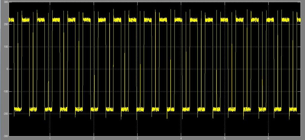
9 (d) Fig 16.Experimental results of the CMV vcm (top) and its FFT (bottom) in the three-phase inverter without a hybrid filter under the conventional SPWM strategy under the CPPM strategy, and with the detection-control hybrid filter (d) with the calculation-control hybrid filter under the CPPM strategy Fig 17.Experimental results of the shaft voltage vshaft (top) and its FFT (bottom) in the three-phase inverter under the conventional SPWM strategy without a hybrid filter, and under the CPPM strategy with the detection-control hybrid filter or with the calculation-control hybrid filter.
 and its FFT (bottom) in the three-phase inverter under the conventional SPWM strategy without a hybrid filter, and under the CPPM strategy with the")
 and its FFT (bottom) in the three-phase inverter under the conventional SPWM strategy under the CPPM strategy without a hybrid filter under the CPPM strategy")
10 Fig 18.Experimental results of the CMC icm (top) and its FFT (bottom) in the three-phase inverter under the conventional SPWM strategy without a hybrid filter, and under the CPPM strategy with the detection-control hybrid filter or with the calculation-control hybrid filter. Fig 19.Experimental results of the DMV vab (top) and its FFT (bottom) in the three-phase inverter under the conventional SPWM strategy under the CPPM strategy without a hybrid filter under the CPPM strategy with the hybrid filter. VI. CONCLUSION In this paper the hybrid filter, which is designed to suppress the CMV and DM harmonics of the three-phase inverter, is proved to have the following characteristics. The method which makes use of such ripple and correlates this with switching function to control the operating point of PV array is called ripple correlation control (RCC). In this paper, a modified RCC method has been proposed to implement the MPPT technique with reduced component count which makes the implementation easier compared to existing techniques presented in literature.1) Simple in structure: The simple structure means lower cost. 2) Easy in installation: As the added active DMV filter and single tuned filter in the hybrid filter are paralleled into the output lines of the inverter, they can be installed conveniently and are very suitable for the revamping of the established system. 3) Flexible in application. 4) Optimized in effectas for the CMV suppression effect, the inverter with the hybrid filter is much better than that without the hybrid filter and the hybrid filter under the
 Compatible in THD standard: The phase-shifting of the carrier in the CPPM strategy enhances the output DM harmonics of the inverter in the carrier frequency band.")

11 calculation-control scheme is superior to that under the detection-control scheme. 5) Compatible in THD standard: The phase-shifting of the carrier in the CPPM strategy enhances the output DM harmonics of the inverter in the carrier frequency band. Compared to existing methods which uses only sign of the error signal generated by the MPPT block, this method uses both magnitude and sign of the error signal which makes the system respond faster. The effectiveness of the proposed method has been verified by using simulation results. indirect matrix converters, IEEE Trans. Ind. Electron., vol. 59, no. 1, pp , Jan [10] N. Zhu, D. Xu, B. Wu, N. R. Zargari, M. Kazerani, and F. Liu, Commonmode voltage reduction methods for current-source converters in mediumvoltagedrives, IEEE Trans. Power Electron., vol. 28, no. 2, pp , Feb REFERENCES [1] Y. Murai, T. Kubota, and Y. Kawase, Leakage current reduction for a high-frequency carrier inverter feeding an induction motor, IEEE Trans. Ind. Appl., vol. 28, no. 4, pp , Jul./Aug [2] G. L. Skibinski, R. J. Kerkman, and D. Schlegel, EMI emissions of modern PWM AC drives, IEEE Ind. Appl. Mag., vol. 5, no. 6, pp , Nov./Dec [3] S. Chen, T. A. Lipo, and D. Fitzgerald, Source of induction motor bearing currents caused by PWM inverters, IEEE Trans. Energy Concers., vol. 11, no. 1, pp , Mar [4] A. Muetze and A. Binder, Calculation of circulating bearing currents in machines of inverterbased drive systems, IEEE Trans. Ind. Electron., vol. 54, no. 2, pp , Apr [5] F. J. T. E. Ferreira, M. V. Cistelecan, and A. T. de Almeida, Evaluation of slot-embedded partial electrostatic shield for high-frequency bearing current mitigation in inverter-fed induction motors, IEEE Trans. Energy Convers., vol. 27, no. 2, pp , Jun [6]D.F.Busse,J.M.Erdman,R.J.Kerkman,D.W.Schleg el,and G. L. Skibinski, The effects of PWM voltage source inverters on the mechanical performance of rolling bearings, IEEE Trans. Ind. Appl., vol. 33, no. 2, pp , Mar./Apr [7] R. S. Araujo, R. A. Rodrigues, H. de Paula, and L. M. R. Baccarini, Premature wear and recurring bearing failures in three-phase induction motors: A case study, IEEE Latin Amer. Trans., vol. 9, no. 4, pp , Jul [8] J. Espina et al., Reduction of output common mode voltage using a novel SVM implementation in matrix converters for improved motor lifetime, IEEE Trans. Ind. Electron., vol. 61, no. 11, pp , Nov [9] T. D. Nguyen and H. H. Lee, Modulation strategies to reduce commonmode voltage for REKHA UMA MAHESH Mr. REKHA UMA MAHESH was born in Rajapudi, AP on June 08, He graduatedfrom Jawaharlal Nehru Technological University, Kakinada. Presently he is studying M.Tech (PE&PS) in QIS College of Engineering and Technology, Ongole, AP. DAKA PRASAD Mr. Daka Prasad was born on Nov 15, He Graduated fromjawaharlal Nehru Technological University; Kakinada. Presently He is working as an Assistant Professor in QIS College of Engineering and Technology, Ongole, AP.
Suppression of Common Mode Voltage and Differential Mode Harmonics in Three Phase Inverter Using Hybrid Filter
 Suppression of Common Mode Voltage and Differential Mode Harmonics in Three Phase Inverter Using Hybrid Filter [1] C.Ganesh [2] S.Saradha [3] P.Haritha [1][2] Assistant Professor [3] PG Student [1][2][3]
IEEE TRANSACTIONS ON INDUSTRIAL ELECTRONICS, VOL. 62, NO. 7, JULY
 IEEE TRANSACTIONS ON INDUSTRIAL ELECTRONICS, VOL. 62, NO. 7, JULY 2015 3991 A Hybrid Filter for the Suppression of Common-Mode Voltage and Differential-Mode Harmonics in Three-Phase Inverters With CPPM
Hybrid filter with CPPM for Suppression of Common Mode Voltage and Differential Mode Harmonics in Three Phase PV Inverter
 International Journal of Electrical Engineering. ISSN 0974-2158 Volume 9, Number 3 (2016), pp. 313-328 International Research Publication House http://www.irphouse.com Hybrid filter with CPPM for Suppression
A Hybrid Filter for the Suppression of Common- Mode Voltage and Differential Mode Harmonics in Three-Phase Inverters with CPPM
 A Hybrid Filter for the Suppression of Common- Mode Voltage and Differential Mode Harmonics in Three-Phase Inverters with CPPM Pannala Priyadarshini & D. Vamshy M.Tech Scholar, Vijay Krishna Institute
Bearing Currents and Shaft Voltage Reduction in Dual-Inverter-Fed Open-End Winding Induction Motor With CMV PWM Methods Employing PID
 Bearing Currents and Shaft Voltage Reduction in Dual-Inverter-Fed Open-End Winding Induction Motor With CMV PWM Methods Employing PID I.Rajya Lakshmi 1 P.V Subba Rao 2 1 PG Scholar (EEE), RK College of
Bearing Currents and Shaft Voltage Reduction in Dual-Inverter-Fed Open-End Winding Induction Motor With CMV PWM Methods Employing PID
 Bearing Currents and Shaft Voltage Reduction in Dual-Inverter-Fed Open-End Winding Induction Motor With CMV PWM Methods Employing PID T.Rakesh 1, K.Suresh 2 1 PG Scholar (PS), Nalanda Institute of Engineering
MODELLING AND SIMULATION OF DIODE CLAMP MULTILEVEL INVERTER FED THREE PHASE INDUCTION MOTOR FOR CMV ANALYSIS USING FILTER
 MODELLING AND SIMULATION OF DIODE CLAMP MULTILEVEL INVERTER FED THREE PHASE INDUCTION MOTOR FOR CMV ANALYSIS USING FILTER Akash A. Chandekar 1, R.K.Dhatrak 2 Dr.Z.J..Khan 3 M.Tech Student, Department of
REDUCTION OF COMMON MODE VOLTAGE IN THREE PHASE GRID CONNECTED CONVERTERS THROUGH NOVEL PWM TECHNIQUES
 REDUCTION OF COMMON MODE VOLTAGE IN THREE PHASE GRID CONNECTED CONVERTERS THROUGH NOVEL PWM TECHNIQUES Ms. B. Vimala Electrical and Electronics Engineering, G. Pulla Reddy Engineering College, Kurnool,
REDUCTION OF COMMON-MODE VOLTAGE IN OPEN END WINDING INDUCTION MOTOR DRIVE USING CARRIER PHASE-SHIFT STRATEGY
 REDUCTION OF COMMON-MODE VOLTAGE IN OPEN END WINDING INDUCTION MOTOR DRIVE USING CARRIER PHASE-SHIFT STRATEGY Ms. C. Kalpa Latha, Electrical and Electronics Engineering, G. Pulla Reddy Engineering College,
Electromagnetic Compatibility and Better Harmonic Performance with Seven Level CHB Converter Based PV-Battery Hybrid System
 Electromagnetic Compatibility and Better Harmonic Performance with Seven Level CHB Converter Based PV-Battery Hybrid System A. S. S. Veerendra Babu 1, G. Kiran Kumar 2 1 M.Tech Scholar, Department of EEE,
An Interleaved High Step-Up Boost Converter With Voltage Multiplier Module for Renewable Energy System
 An Interleaved High Step-Up Boost Converter With Voltage Multiplier Module for Renewable Energy System Vahida Humayoun 1, Divya Subramanian 2 1 P.G. Student, Department of Electrical and Electronics Engineering,
Mr. DILIP J. Final Year Mtech Student Dept of EEE The Oxford College of Engineering, Bangalore
 International Journal of Research Studies in Electrical and Electronics Engineering (IJRSEEE) Volume 1, Issue 1, June 2015, PP 9-17 www.arcjournals.org The Proposed Research Technology and Data Implementation
A Novel Cascaded Multilevel Inverter Using A Single DC Source
 A Novel Cascaded Multilevel Inverter Using A Single DC Source Nimmy Charles 1, Femy P.H 2 P.G. Student, Department of EEE, KMEA Engineering College, Cochin, Kerala, India 1 Associate Professor, Department
Simulation of Three Phase Cascaded H Bridge Inverter for Power Conditioning Using Solar Photovoltaic System
 Simulation of Three Phase Cascaded H Bridge Inverter for Power Conditioning Using Solar Photovoltaic System 1 G.Balasundaram, 2 Dr.S.Arumugam, 3 C.Dinakaran 1 Research Scholar - Department of EEE, St.
THREE PHASE INVERTER USING COUPLED INDUCTOR FOR GRID CONNECTED PHOTOVOLTAIC SYSTEM
 THREE PHASE INVERTER USING COUPLED INDUCTOR FOR GRID CONNECTED PHOTOVOLTAIC SYSTEM G.KANIMOZHI.ME.,Mrs.S.RAKKAMMAL.ME., Mail id:gkmozhi1@gmail.com Mail id:rakkammalram@yahoo.com_ 9159719678 8124408556
Common Mode Voltage Reduction in a Three Level Neutral Point Clamped Inverter Using Modified SVPWM
 Common Mode Voltage Reduction in a Three Level Neutral Point Clamped Inverter Using Modified SVPWM Asna Shanavas Shamsudeen 1, Sandhya. P 2 P.G. Student, Department of Electrical and Electronics Engineering,
Grid Connected Photovoltaic Micro Inverter System using Repetitive Current Control and MPPT for Full and Half Bridge Converters
 Ch.Chandrasekhar et. al. / International Journal of New Technologies in Science and Engineering Vol. 2, Issue 6,Dec 2015, ISSN 2349-0780 Grid Connected Photovoltaic Micro Inverter System using Repetitive
International Journal of Advance Research in Engineering, Science & Technology
 Impact Factor (JIF): 3.632 International Journal of Advance Research in Engineering, cience & Technology e-in: 2393-9877, p-in: 2394-2444 (pecial Issue for ITECE 2016) A Novel PWM Technique to Reduce Common
CHAPTER 1 INTRODUCTION
 CHAPTER 1 INTRODUCTION 1.1 Introduction Power semiconductor devices constitute the heart of the modern power electronics, and are being extensively used in power electronic converters in the form of a
Active damping of output LC filter resonance for vector controlled VSI- fed AC motor drive
 The International Journal Of Engineering And Science (IJES) Volume 3 Issue 6 Pages 50-56 2014 ISSN (e): 2319 1813 ISSN (p): 2319 1805 Active damping of output LC filter resonance for vector controlled
Reduction of Harmonics and Torque Ripples of BLDC Motor by Cascaded H-Bridge Multi Level Inverter Using Current and Speed Control Techniques
 Reduction of Harmonics and Torque Ripples of BLDC Motor by Cascaded H-Bridge Multi Level Inverter Using Current and Speed Control Techniques A. Sneha M.Tech. Student Scholar Department of Electrical &
Simulation & Implementation Of Three Phase Induction Motor On Single Phase By Using PWM Techniques
 Simulation & Implementation Of Three Phase Induction Motor On Single Phase By Using PWM Techniques Ashwini Kadam 1,A.N.Shaikh 2 1 Student, Department of Electronics Engineering, BAMUniversity,akadam572@gmail.com,9960158714
Three Level Three Phase Cascade Dual-Buck Inverter With Unified Pulsewidth Modulation
 IOSR Journal of Engineering (IOSRJEN) e-issn: 2250-3021, p-issn: 2278-8719 Vol. 3, Issue 4 (July. 2013), V1 PP 38-43 Three Level Three Phase Cascade Dual-Buck Inverter With Unified Pulsewidth Modulation
RECENTLY, the harmonics current in a power grid can
 IEEE TRANSACTIONS ON POWER ELECTRONICS, VOL. 23, NO. 2, MARCH 2008 715 A Novel Three-Phase PFC Rectifier Using a Harmonic Current Injection Method Jun-Ichi Itoh, Member, IEEE, and Itsuki Ashida Abstract
Solar fed Induction Motor Drive with TIBC Converter and Voltage Multiplier Circuit
 Solar fed Induction Motor Drive with TIBC Converter and Voltage Multiplier Circuit Aiswarya s. Nair 1, Don Cyril Thomas 2 MTech 1, Assistant Professor 2, Department of Electrical and Electronics St. Joseph
A Single Phase Multistring Seven Level Inverter for Grid Connected PV System
 A Single Phase Multistring Seven Level Inverter for Grid Connected PV System T.Sripal Reddy, M.Tech, (Ph.D) Associate professor & HoD K. Raja Rao, M.Tech Assistat Professor Padrthi Anjaneyulu M.Tech Student
Modelling and Simulation of New PV-Battery Based Hybrid Energy System for Z source Inverter using SVPWM fed Industrial Applications
 Modelling and Simulation of New PV-Battery Based Hybrid Energy System for Z source Inverter using SVPWM fed Industrial Applications VEERESH M-Tech Scholar Department of Electrical & Electronics Engineering,
Minimization Of Total Harmonic Distortion Using Pulse Width Modulation Technique
 IOSR Journal of Electrical and Electronics Engineering (IOSR-JEEE) e-issn: 2278-1676,p-ISSN: 2320-3331, Volume 10, Issue 3 Ver. IV (May Jun. 2015), PP 01-12 www.iosrjournals.org Minimization Of Total Harmonic
Determination of EMI of PWM fed Three Phase Induction Motor. Ankur Srivastava
 Abstract International Journal of Technical Innovation in Modern Engineering & Science (IJTIMES) Impact Factor: 3.45 (SJIF-2015), e-issn: 2455-2584 Volume 3, Issue 05, May-2017 Determination of EMI of
Buck-Boost Converter based Voltage Source Inverter using Space Vector Pulse Width Amplitude modulation Jeetesh Gupta 1 K.P.Singh 2
 IJSRD - International Journal for Scientific Research & Development Vol. 2, Issue 06, 2014 ISSN (online): 2321-0613 Buck-Boost Converter based Voltage Source Inverter using Space Vector Pulse Width Amplitude
Energetic PV Cell Based Power Supply Management Using Modified Quasi-Z-Source Inverter
 Energetic PV Cell Based Power Supply Management Using Modified Quasi-Z-Source Inverter SREEKANTH C 1, VASANTHI V 2 1 MTech student, 2 Professor Department of Electrical and Electronics NSS College of Engineering,
International Journal of Engineering Science Invention Research & Development; Vol. II Issue VIII February e-issn:
 ANALYSIS AND DESIGN OF SOFT SWITCHING BASED INTERLEAVED FLYBACK CONVERTER FOR PHOTOVOLTAIC APPLICATIONS K.Kavisindhu 1, P.Shanmuga Priya 2 1 PG Scholar, 2 Assistant Professor, Department of Electrical
Effective Algorithm for Reducing DC Link Neutral Point Voltage and Total Harmonic Distortion for Five Level Inverter
 Effective Algorithm for Reducing DC Link Neutral Point Voltage Total Harmonic Distortion for Five Level Inverter S. Sunisith 1, K. S. Mann 2, Janardhan Rao 3 sunisith@gmail.com, hodeee.gnit@gniindia.org,
SVPWM Technique for Cuk Converter
 Indian Journal of Science and Technology, Vol 8(15), DOI: 10.17485/ijst/2015/v8i15/54254, July 2015 ISSN (Print) : 0974-6846 ISSN (Online) : 0974-5645 SVPWM Technique for Cuk Converter R. Lidha O. R. Maggie*
High Efficiency Single Phase Transformer less PV Multilevel Inverter
 International Journal of Emerging Engineering Research and Technology Volume 1, Issue 1, November 2013, PP 18-22 High Efficiency Single Phase Transformer less PV Multilevel Inverter Preethi Sowjanya M.Tech,
The Selective Harmonic Elimination Technique for Harmonic Reduction of Multilevel Inverter Using PSO Algorithm
 The Selective Harmonic Elimination Technique for Harmonic Reduction of Multilevel Inverter Using PSO Algorithm Maruthupandiyan. R 1, Brindha. R 2 1,2. Student, M.E Power Electronics and Drives, Sri Shakthi
Hybrid Active Power Filters for Reactive Power Compensation with Adaptive DC-Link Voltage Control
 International Journal of Scientific Engineering and Research (IJSER) Hybrid Active Power Filters for Reactive Power Compensation with Adaptive DC-Link Voltage Control Rahul Kumar Patel 1, S. Subha 2 Abstract:
Low Order Harmonic Reduction of Three Phase Multilevel Inverter
 Journal of Scientific & Industrial Research Vol. 73, March 014, pp. 168-17 Low Order Harmonic Reduction of Three Phase Multilevel Inverter A. Maheswari 1 and I. Gnanambal 1 Department of EEE, K.S.R College
COMMON mode current due to modulation in power
 982 IEEE TRANSACTIONS ON POWER ELECTRONICS, VOL. 14, NO. 5, SEPTEMBER 1999 Elimination of Common-Mode Voltage in Three-Phase Sinusoidal Power Converters Alexander L. Julian, Member, IEEE, Giovanna Oriti,
Transformerless Grid-Connected Inverters for Photovoltaic Modules: A Review
 International Journal of Engineering and Technical Research (IJETR) ISSN: 2321-869, Volume 3, Issue 4, April 215 Transformerless Grid-Connected Inverters for Photovoltaic Modules: A Review Sushant S. Paymal,
Speed Control of Induction Motor using Space Vector Modulation
 SSRG International Journal of Electrical and Electronics Engineering (SSRG-IJEEE) volume Issue 12 December 216 Speed Control of Induction Motor using Space Vector Modulation K Srinivas Assistant Professor,
Measurement and reduction of EMI radiated by a PWM inverter-fed AC motor drive system
 Engineering Electrical Engineering fields Okayama University Year 1997 Measurement and reduction of EMI radiated by a PWM inverter-fed AC motor drive system Satoshi Ogasawara Okayama University Hirofumi
POWERED electronic equipment with high-frequency inverters
 IEEE TRANSACTIONS ON CIRCUITS AND SYSTEMS II: EXPRESS BRIEFS, VOL. 53, NO. 2, FEBRUARY 2006 115 A Novel Single-Stage Power-Factor-Correction Circuit With High-Frequency Resonant Energy Tank for DC-Link
OUTLINE. Introduction. Introduction. Conducted Electromagnetic Interference in Smart Grids. Introduction. Introduction
 Robert Smoleński Institute of Electrical Engineering University of Zielona Gora Conducted Electromagnetic Interference in Smart Grids Introduction Currently there is lack of the strict, established definition
Enhanced Performance of Multilevel Inverter Fed Induction Motor Drive
 Enhanced Performance of Multilevel Inverter Fed Induction Motor Drive Venkata Anil Babu Polisetty 1, B.R.Narendra 2 PG Student [PE], Dept. of EEE, DVR. & Dr.H.S.MIC College of Technology, AP, India 1 Associate
DIRECT TORQUE CONTROL OF THREE PHASE INDUCTION MOTOR BY USING FOUR SWITCH INVERTER
 DIRECT TORQUE CONTROL OF THREE PHASE INDUCTION MOTOR BY USING FOUR SWITCH INVERTER Mr. Aniket C. Daiv. TSSM's BSCOER, Narhe ABSTRACT Induction motor proved its importance, since its invention and has been
Soft Switching with Cascaded Transformers to Drive the PMDC Motor
 Soft Switching with Cascaded Transformers to Drive the PMDC Motor P.Ranjitha 1, V.Dhinesh 2, Dr.M.Muruganandam 3 PG Student [PED], Dept. of EEE, Muthayammal Engineering College, Salem, Tamilnadu, India
International Journal of Advance Engineering and Research Development
 Scientific Journal of Impact Factor (SJIF): 3.134 International Journal of Advance Engineering and Research Development Volume 3, Issue 1, January -2016 e-issn (O): 2348-4470 p-issn (P): 2348-6406 Design
CHAPTER 3 SINGLE SOURCE MULTILEVEL INVERTER
 42 CHAPTER 3 SINGLE SOURCE MULTILEVEL INVERTER 3.1 INTRODUCTION The concept of multilevel inverter control has opened a new avenue that induction motors can be controlled to achieve dynamic performance
MMC based D-STATCOM for Different Loading Conditions
 International Journal of Engineering Research And Management (IJERM) ISSN : 2349-2058, Volume-02, Issue-12, December 2015 MMC based D-STATCOM for Different Loading Conditions D.Satish Kumar, Geetanjali
Hybrid Modulation Technique for Cascaded Multilevel Inverter for High Power and High Quality Applications in Renewable Energy Systems
 International Journal of Electronic and Electrical Engineering. ISSN 0974-2174 Volume 5, Number 1 (2012), pp. 59-68 International Research Publication House http://www.irphouse.com Hybrid Modulation Technique
A Series-Connected Multilevel Inverter Topology for Squirrel-Cage Induction Motor Drive
 Vol.2, Issue.3, May-June 2012 pp-1028-1033 ISSN: 2249-6645 A Series-Connected Multilevel Inverter Topology for Squirrel-Cage Induction Motor Drive B. SUSHMITHA M. tech Scholar, Power Electronics & Electrical
Student Department of EEE (M.E-PED), 2 Assitant Professor of EEE Selvam College of Technology Namakkal, India
, 2 Assitant Professor of EEE Selvam College of Technology Namakkal, India") Design and Development of Single Phase Bridgeless Three Stage Interleaved Boost Converter with Fuzzy Logic Control System M.Pradeep kumar 1, M.Ramesh kannan 2 1 Student Department of EEE (M.E-PED), 2 Assitant
Design and Development of Single Phase Bridgeless Three Stage Interleaved Boost Converter with Fuzzy Logic Control System M.Pradeep kumar 1, M.Ramesh kannan 2 1 Student Department of EEE (M.E-PED), 2 Assitant
ABHINAV NATIONAL MONTHLY REFEREED JOURNAL OF RESEARCH IN SCIENCE & TECHNOLOGY
 HIGH PERFORMANCE PV-BATTERY HYBRID SYSTEM WITH MULTILEVEL INVERTER FED TO INDUCTION MOTOR DRIVE AND TOTAL HARMONIC DISTROTION ANALYSIS N.Triveni 1, Dr.K.Ravichandrudu 2 and P. Yohan Babu 3 1 PG Student,
DOWNLOAD PDF POWER ELECTRONICS DEVICES DRIVERS AND APPLICATIONS
 Chapter 1 : Power Electronics Devices, Drivers, Applications, and Passive theinnatdunvilla.com - Google D Download Power Electronics: Devices, Drivers and Applications By B.W. Williams - Provides a wide
A Hybrid Cascaded Multilevel Inverter for Interfacing with Renewable Energy Resources
 A Hybrid Cascaded Multilevel Inverter for Interfacing with Renewable Energy Resources P.Umapathi Reddy 1, S.Sivanaga Raju 2 Professor, Dept. of EEE, Sree Vidyanikethan Engineering College, Tirupati, A.P.
HIGH EFFICIENCY TRANSFORMER LESS INVERTER FOR SINGLE-PHASE PHOTOVOLTAIC SYSTEMS USING SWITCHING CONVERTER
 HIGH EFFICIENCY TRANSFORMER LESS INVERTER FOR SINGLE-PHASE PHOTOVOLTAIC SYSTEMS USING SWITCHING CONVERTER S.Satheesh 1, K.Lingashwaran 2 PG Scholar 1, Lecturer 2 Bharath University Abstract - There is
Switching of Three Phase Cascade Multilevel Inverter Fed Induction Motor Drive
 pp 36 40 Krishi Sanskriti Publications http://www.krishisanskriti.org/areee.html Switching of Three Phase Cascade Multilevel Inverter Fed Induction Motor Drive Ms. Preeti 1, Prof. Ravi Gupta 2 1 Electrical
B. Muralidhara Member, IACSIT, A. Ramachandran, R. Srinivasan, and M. Channa Reddy
 Experimental Measurement and Comparison of Common Mode Voltage, Shaft Voltage and the Bearing Current in Two-level and Multilevel Fed Induction Motor B. Muralidhara Member, IACSIT, A. Ramachandran, R.
PERFORMANCE ANALYSIS OF SOLAR POWER GENERATION SYSTEM WITH A SEVEN-LEVEL INVERTER SUDHEER KUMAR Y, PG STUDENT CHANDRA KIRAN S, ASSISTANT PROFESSOR
 PERFORMANCE ANALYSIS OF SOLAR POWER GENERATION SYSTEM WITH A SEVEN-LEVEL INVERTER SUDHEER KUMAR Y, PG STUDENT CHANDRA KIRAN S, ASSISTANT PROFESSOR KV SUBBA REDDY INSTITUTE OF TECHNOLOGY, KURNOOL Abstract:
CHAPTER 3 APPLICATION OF THE CIRCUIT MODEL FOR PHOTOVOLTAIC ENERGY CONVERSION SYSTEM
 63 CHAPTER 3 APPLICATION OF THE CIRCUIT MODEL FOR PHOTOVOLTAIC ENERGY CONVERSION SYSTEM 3.1 INTRODUCTION The power output of the PV module varies with the irradiation and the temperature and the output
A Switched Boost Inverter Fed Three Phase Induction Motor Drive
 A Switched Boost Inverter Fed Three Phase Induction Motor Drive 1 Riya Elizabeth Jose, 2 Maheswaran K. 1 P.G. student, 2 Assistant Professor 1 Department of Electrical and Electronics engineering, 1 Nehru
TRANSFORMERLESS THREE LEVEL DIODE CLAMPED INVERTER FOR SINGLE PHASE GRID CONNECTED PHOTOVOLTAIC SYSTEM
 INTERNATIONAL JOURNAL OF ELECTRICAL ENGINEERING & TECHNOLOGY (IJEET) Proceedings of the International Conference on Emerging Trends in Engineering and Management (ICETEM14) ISSN 0976 6545(Print) ISSN 0976
Simulation of Standalone PV System Using P&O MPPT Technique in Matlab/Simulink
 International Journal of Engineering Research and Development (IJERD) ISSN: 2278-067X (Page 72-77) Simulation of Standalone PV System Using P&O MPPT Technique in Matlab/Simulink Keyurkumar Patel 1, Kedar
MPPT based New Transformer Less PV Inverter Topology with Low Leakage Current
 IJIRST International Journal for Innovative Research in Science & Technology Volume 1 Issue 12 May 215 ISSN (online): 2349-61 MPPT based New Transformer Less PV Archu S Vijay PG Student Department of Electrical
CHAPTER 4 MODIFIED H- BRIDGE MULTILEVEL INVERTER USING MPD-SPWM TECHNIQUE
 58 CHAPTER 4 MODIFIED H- BRIDGE MULTILEVEL INVERTER USING MPD-SPWM TECHNIQUE 4.1 INTRODUCTION Conventional voltage source inverter requires high switching frequency PWM technique to obtain a quality output
CHAPTER 1 INTRODUCTION
 1 CHAPTER 1 INTRODUCTION 1.1 GENERAL Induction motor drives with squirrel cage type machines have been the workhorse in industry for variable-speed applications in wide power range that covers from fractional
Space Vector PWM and Model Predictive Control for Voltage Source Inverter Control
 Space Vector PWM and Model Predictive Control for Voltage Source Inverter Control Irtaza M. Syed, Kaamran Raahemifar Abstract In this paper, we present a comparative assessment of Space Vector Pulse Width
@IJMTER-2016, All rights Reserved 241
 Design of Active Buck Boost Inverter for AC applications Vijaya Kumar.C 1,Shasikala.G 2 PG Student 1, Assistant Professor 2 Department of Electrical and Electronics Engineering, Er.Perumal Manimekalai
Multilevel Inverter for Single Phase System with Reduced Number of Switches
 IOSR Journal of Electrical and Electronics Engineering (IOSR-JEEE) e-issn: 2278-1676 Volume 4, Issue 3 (Jan. - Feb. 2013), PP 49-57 Multilevel Inverter for Single Phase System with Reduced Number of Switches
Photo Voltaic Systems Power Optimization under Cascaded Inverter Environment
 Photo Voltaic Systems Power Optimization under Cascaded Inverter Environment Mr.Guruprasad G PG Scholar (M.Tech), Department of Electrical and Electronics Engineering, Ballari Institute of Technology and
Space vector pulse width modulation for 3-phase matrix converter fed induction drive
 Space vector pulse width modulation for 3-phase matrix converter fed induction drive D. Sattianadan 1, R. Palanisamy 2, K. Vijayakumar 3, D.Selvabharathi 4, K.Selvakumar 5, D.Karthikeyan 6 1,2,4,5,6 Assistant
Phase Shift Modulation of a Single Dc Source Cascaded H-Bridge Multilevel Inverter for Capacitor Voltage Regulation with Equal Power Distribution
 Phase Shift Modulation of a Single Dc Source Cascaded H-Bridge Multilevel Inverter for Capacitor Voltage Regulation with Equal Power Distribution K.Srilatha 1, Prof. V.Bugga Rao 2 M.Tech Student, Department
A Novel Four Switch Three Phase Inverter Controlled by Different Modulation Techniques A Comparison
 Volume 2, Issue 1, January-March, 2014, pp. 14-23, IASTER 2014 www.iaster.com, Online: 2347-5439, Print: 2348-0025 ABSTRACT A Novel Four Switch Three Phase Inverter Controlled by Different Modulation Techniques
A SPWM CONTROLLED THREE-PHASE UPS FOR NONLINEAR LOADS
 http:// A SPWM CONTROLLED THREE-PHASE UPS FOR NONLINEAR LOADS Abdul Wahab 1, Md. Feroz Ali 2, Dr. Abdul Ahad 3 1 Student, 2 Associate Professor, 3 Professor, Dept.of EEE, Nimra College of Engineering &
Design and Implementation of Three Phase Γ-Z Source Inverter for Asynchronous Motor
 International Journal of Electrical Engineering. ISSN 0974-158 Volume 7, Number (014), pp. 345-35 International Research Publication House http://www.irphouse.com Design and Implementation of Three Phase
REDUCTION OF ZERO SEQUENCE VOLTAGE USING MULTILEVEL INVERTER FED OPEN-END WINDING INDUCTION MOTOR DRIVE
 52 Acta Electrotechnica et Informatica, Vol. 16, No. 4, 2016, 52 60, DOI:10.15546/aeei-2016-0032 REDUCTION OF ZERO SEQUENCE VOLTAGE USING MULTILEVEL INVERTER FED OPEN-END WINDING INDUCTION MOTOR DRIVE
Z-SOURCE INVERTER BASED DVR FOR VOLTAGE SAG/SWELL MITIGATION
 Z-SOURCE INVERTER BASED DVR FOR VOLTAGE SAG/SWELL MITIGATION 1 Arsha.S.Chandran, 2 Priya Lenin 1 PG Scholar, 2 Assistant Professor 1 Electrical & Electronics Engineering 1 Mohandas College of Engineering
A Three-Phase AC-AC Buck-Boost Converter using Impedance Network
 A Three-Phase AC-AC Buck-Boost Converter using Impedance Network Punit Kumar PG Student Electrical and Instrumentation Engineering Department Thapar University, Patiala Santosh Sonar Assistant Professor
Literature Survey: Multilevel Voltage Source Inverter With Optimized Convention Of Bidirectional Switches
 Literature Survey: Multilevel Voltage Source Inverter With Optimized Convention Of Bidirectional Switches P.Bhagya [1], M.Thangadurai [2], V.Mohamed Ibrahim [3] PG Scholar [1],, Assistant Professor [2],
Analysis of Advanced PWM Algorithms Based on Simplified Sequence for Reduced CMV in Induction Motor Drive
 International Journal of Engineering and Advanced echnology (IJEA) ISSN: 2249 8958, olume-4 Issue 1, October 2014 Analysis of Advanced PWM Algorithms Based on Simplified Sequence for Reduced CM in Induction
Simulation And Comparison Of Space Vector Pulse Width Modulation For Three Phase Voltage Source Inverter
 Simulation And Comparison Of Space Vector Pulse Width Modulation For Three Phase Voltage Source Inverter Associate Prof. S. Vasudevamurthy Department of Electrical and Electronics Dr. Ambedkar Institute
A Three Phase Seven Level Inverter for Grid Connected Photovoltaic System by Employing PID Controller
 A Three Phase Seven Level Inverter for Grid Connected Photovoltaic System by Employing PID Controller S. Ragavan, Swaminathan 1, R.Anand 2, N. Ranganathan 3 PG Scholar, Dept of EEE, Sri Krishna College
Grid connected Boost-Full-Bridge photovoltaic microinverter system using Phase Opposition Disposition technique and Maximum Power Point Tracking
 IOSR Journal of Electrical and Electronics Engineering (IOSR-JEEE) e-issn: 2278-1676,p-ISSN: 2320-3331, Volume 9, Issue 1 Ver. II (Jan. 2014), PP 47-55 Grid connected Boost-Full-Bridge photovoltaic microinverter
PV PANEL WITH CIDBI (COUPLED INDUCTANCE DOUBLE BOOST TOPOLOGY) DC-AC INVERTER
 DC-AC INVERTER") PV PANEL WITH CIDBI (COUPLED INDUCTANCE DOUBLE BOOST TOPOLOGY) DC-AC INVERTER Mr.Thivyamoorthy.S 1,Mrs.Bharanigha 2 Abstract--In this paper the design and the control of an individual PV panel dc-ac converter
PV PANEL WITH CIDBI (COUPLED INDUCTANCE DOUBLE BOOST TOPOLOGY) DC-AC INVERTER Mr.Thivyamoorthy.S 1,Mrs.Bharanigha 2 Abstract--In this paper the design and the control of an individual PV panel dc-ac converter
A New Control Method for Balancing of DC-Link Voltage and Elimination of Common Mode Voltage in Multi-level Inverters
 A New Control Method for Balancing of DC-Link Voltage and Elimination of Common Mode Voltage in Multi-level Inverters P. Satish Kumar Department of Electrical Engineering University College of Engineering,
Economic Single-Phase to Three-Phase Converter for Low Power Motor Drives
 Economic Single-Phase to Three-Phase Converter for Low Power Motor Drives Nidhin Jose B.Tech Student, Electrical and Electronics Engineering Dept., A P J Abdul Kalam Technological University, Kerala, India
Multilevel Current Source Inverter Based on Inductor Cell Topology
 Multilevel Current Source Inverter Based on Inductor Cell Topology A.Haribasker 1, A.Shyam 2, P.Sathyanathan 3, Dr. P.Usharani 4 UG Student, Dept. of EEE, Magna College of Engineering, Chennai, Tamilnadu,
Levels of Inverter by Using Solar Array Generation System
 Levels of Inverter by Using Solar Array Generation System Ganesh Ashok Ubale M.Tech (Digital Systems) E&TC, Government College of Engineering, Jalgaon, Maharashtra. Prof. S.O.Dahad, M.Tech HOD, (E&TC Department),
SIMULATION of EMC PERFORMANCE of GRID CONNECTED PV INVERTERS
 SIMULATION of EMC PERFORMANCE of GRID CONNECTED PV INVERTERS Qin Jiang School of Communications & Informatics Victoria University P.O. Box 14428, Melbourne City MC 8001 Australia Email: jq@sci.vu.edu.au
Comparative Analysis of Flying Capacitor and Cascaded Multilevel Inverter Topologies using SPWM
 Comparative Analysis of Flying Capacitor and Cascaded Multilevel Inverter Topologies using SPWM Akhila.A #1, Manju Ann Mathews *2, Dr.Nisha.G.K #3 # PG Scholar, Department of EEE, Kerala University, Trivandrum,
PF and THD Measurement for Power Electronic Converter
 PF and THD Measurement for Power Electronic Converter Mr.V.M.Deshmukh, Ms.V.L.Jadhav Department name: E&TC, E&TC, And Position: Assistant Professor, Lecturer Email: deshvm123@yahoo.co.in, vandanajadhav19jan@gmail.com
POWER QUALITY IMPROVEMENT BY USING ACTIVE POWER FILTERS
 POWER QUALITY IMPROVEMENT BY USING ACTIVE POWER FILTERS Saheb Hussain MD 1, K.Satyanarayana 2, B.K.V.Prasad 3 1 Assistant Professor, EEE Department, VIIT, A.P, India, saheb228@vignanvizag.com 2 Ph.D Scholar,
Multilevel inverter with cuk converter for grid connected solar PV system
 I J C T A, 9(5), 2016, pp. 215-221 International Science Press Multilevel inverter with cuk converter for grid connected solar PV system S. Dellibabu 1 and R. Rajathy 2 ABSTRACT A Multilevel Inverter with
MPPT with Z Impedance Booster
 International Journal of Electrical Engineering. ISSN 0974-2158 Volume 7, Number 3 (2014), pp. 475-483 International Research Publication House http://www.irphouse.com MPPT with Z Impedance Booster Govind
Performance Analysis of Switched Capacitor Three Phase Symmetrical Inverter Topology with Induction Drive
 Performance Analysis of Switched Capacitor Three Phase Symmetrical Inverter Topology with Induction Drive KATURI MAHESH M-tech Student Scholar Department of Electrical & Electronics Engineering, Malla
Performance Metric of Z Source CHB Multilevel Inverter FED IM for Selective Harmonic Elimination and THD Reduction
 Circuits and Systems, 2016, 7, 3794-3806 http://www.scirp.org/journal/cs ISSN Online: 2153-1293 ISSN Print: 2153-1285 Performance Metric of Z Source CHB Multilevel Inverter FED IM for Selective Harmonic
IJCSIET--International Journal of Computer Science information and Engg., Technologies ISSN
 A novel control strategy for Mitigation of Inrush currents in Load Transformers using Series Voltage source Converter Pulijala Pandu Ranga Rao *1, VenuGopal Reddy Bodha *2 #1 PG student, Power Electronics
Power Factor Correction of LED Drivers with Third Port Energy Storage
 Power Factor Correction of LED Drivers with Third Port Energy Storage Saeed Anwar Mohamed O. Badawy Yilmaz Sozer sa98@zips.uakron.edu mob4@zips.uakron.edu ys@uakron.edu Electrical and Computer Engineering
THE greatest drawback of modular multilevel topologies,
 IEEE TRANSACTIONS ON POWER ELECTRONICS, VOL. 31, NO. 10, OCTOBER 2016 6765 Letters Quasi Two-Level PWM Operation of an MMC Phase Leg With Reduced Module Capacitance Axel Mertens and Jakub Kucka Abstract