USER MANUAL. RC100, RC120 LED Lighting Controller Revision 001. RC100, RC120 LED Lighting Controller Revision 001
|
|
|
- Coleen Newman
- 5 years ago
- Views:
Transcription

1 USER MANUAL RC100, RC120 LED Lighting Controller Revision 001 RC100, RC120 LED Lighting Controller Revision 001 Gardasoft Vision Ltd Trinity Court Buckingway Business Park Cambridge, CB24 4UQ UK Gardasoft LLC Oak Ridge Rd Weare, NH USA Web:
2 2 Except as prohibited by law: 1 Disclaimer Hardware, software and documentation are provided on an as is basis. It is essential that the user ensures that the operation of the product is suitable for their application. The user must ensure that incorrect functioning of this equipment cannot cause any dangerous situation or significant financial loss to occur. Gardasoft Vision Ltd and Gardasoft Products Ltd do not accept any liability for consequential loss of any kind. All trademarks acknowledged. Hardware, software and documentation are Copyright Gardasoft Products Ltd. Hardware manufactured by Gardasoft Vision Ltd under licence. 2 Getting Started Read Section 3: Safety, and Specifications (Appendix A) and check the RC1XX fulfils your requirements. See the back cover for other Gardasoft Vision lighting products. Mount the RC1XX as described in Section 4. Connect the RC1XX up to a power supply as described in Section 5: Connections. When the front panel is present, the RC1XX shows two alternating lines on the display to indicate that it is operating normally. Read section 7 on Lighting Setup, enter the current or voltage rating of the lights to be connected and then connect the lights. Set up the RC1XX for the desired operation as described in the configuration sections 8, 10 and 11. Visit for application notes on this product. There is also a Support page which has information on troubleshooting problems. The RC1XX may emit a slight noise when operating.
3 RC100 and RC120: Throughout this manual, references to RC1XX refer to both the RC100 and RC120. The following table lists the differences between the models. Number of channels Front panel configuration Ethernet configuration Max current output (continuous) Max current output (pulsed) RC100 1 Yes No 1A 1A RC120 1 Yes Yes 1.2A 2A
4 4 3 Safety Read this before using the RC1XX. Always observe the following safety precautions. If in doubt, contact your distributor or Gardasoft Vision. The following symbols mean: Warning: read instructions to understand possible hazard Warning: Surface may get hot Where these symbols appear in the manual, refer to the text for precautions to be taken. 3.1 Heat Read Section 4: Mounting. Do not exceed the power ratings given in the manual. Note: At the maximum ratings the case temperature can reach 65 o C. Allow free flow of air around the unit. 3.2 Electrical The RC1XX does not have complete tracking isolation of inputs and outputs. Transients caused by inductive loads must be suppressed external to the RC1XX. The RC1XX outputs high energy pulses. Care must be taken to connect the outputs correctly and protect the output wiring and load from inadvertent short-circuits. When switched off, there is still energy stored in the RC1XX for about 15 seconds. 3.3 General The RC1XX must not be used in an application where its failure could cause a danger to personal health or damage to other equipment. If the equipment is used in a manner not specified by the manufacturer, the protection provided by the equipment may be impaired. Cleaning: Unit must be switched off. Wipe with a cloth dampened with water and detergent. No solvents or other cleaning agents to be used.


5 4 Mounting The RC1XX is designed to be mounted on a DIN rail. 4.1 Environmental considerations Mount the unit vertically or horizontally on the DIN rail to allow the display to be easily read. When the average power output is more than 15W (see section on Operation) the RC1XX should be mounted in the orientation shown below such that air can move vertically through the controller. The RC1XX has an ingress rating of IP20 and should be mounted so that moisture and dirt cannot enter the unit. Dimensions: 5


6 6 Connectors: Ethernet (RC120 only) Trigger Input Power Supply Input Lighting Output
7 5 Connections See the Specification (Appendix A) for information on RC1XX ratings. 5.1 Power Supply Any power supply derived from the mains must have a SELV output. The power supply input is fused internally with a non-replaceable fuse. All low voltage wiring to the RC1xx should be routed separately from mains wiring. If they must be loomed together ensure that low voltage insulation rating is sufficient or that supplementary insulation is used. 7 Pin Power Input Connector 1 +24V +/-10% 2 GND 5.2 Lighting Output Make sure you set the current or voltage rating for a light before connecting it. See the Lighting Setup (Section 7) for details on this. Light output is on 2-way pluggable screw terminal socket. The lighting output connections must not be commoned to any other controllers or grounded in any way. Pin Output Connector 1 Lighting output +ve 2 Lighting output ve This connection is not connected to GND.
8 8 5.3 Trigger Input The trigger input is a Smart Input. This is designed to handle a range of trigger sources with minimal extra circuitry. The connections are: Pin Trigger connector 1 No connect 2 No connect 3 +VE (Smart trigger input) 4 GND Note that the Smart Input is not isolated, it is ground-referenced to the power supply negative connection. The Smart Input can be connected to the following types of signal. 3V to 24V voltage source A voltage signal of 0V to 0.9V will be taken as a logic 0. A voltage signal of 3V to 24V will be taken as a logic 1. TTL Signal A TTL signal can be connected to the input. 5V TTL signals will always work. A 3.3V TTL signal will work as long as the signal can drive 50kohm up to 2.7V.


9 NPN Signal An NPN open collector drive can be connected to the input using the following connections. 9 Opto-coupler Connected as follows this works as an NPN drive. This would be the preferred method for preventing a ground loop, or for reducing spurious triggering in a high-interference environment. PNP Signal A PNP open collector drive can be connected to the input using the following connections. The PNP transistor should not pull up to more than 24V.
10 Ethernet Connection (RC120) The RJ45 Ethernet connector requires a straight-through cable to connect into a network switch, hub or router. It operates at 10Mbits per second (10Base-T). 5.4 Connectors The RC1XX packaging includes mating connectors for the power supply input, trigger inputs, and lighting output. Should spare parts be required these can be obtained as follows: Connector Description Wuerth part number Power Input Trigger Input Lighting Output Wuerth 351 series 2W screw terminal free socket Wuerth 361 series 4W screw terminal free socket Wuerth 348 series 2W screw terminal free plug Farnell part number N/A
11 6 General Description 11 The RC1XX current controller provides repeatable control of LED lighting for machine vision applications. It includes the intensity control, timing and triggering functions required for machine vision systems. LED lighting needs a constant current supply as small variations in voltage can cause large variations in light output. The RC1XX can set currents in steps of 0.1% (with a lower limit of 2.5mA steps) to give very fine control of intensity. Several modes of operation are separately available: Continuous ( SCo ): In continuous mode the output is a continuous brightness. Pulse (Strobe) ( SPu ): In pulse mode output is pulsed once per trigger. One trigger input is used as a trigger. The delay from trigger to pulse, the pulse duration and the brightness can be set. Switched ( SOn ): In switched mode a trigger input is used to switch the output current on and off. The RC1XX is set up using the push buttons and display on the front of the unit. The set up is non-volatile, so the RC1XX resumes the same operation after a power cycle. 6.1 SafeSense SafeSense is a technology unique to Gardasoft controllers. SafeSense works by using the following techniques: Lighting detection Determination of current rating Safe driving of lighting Detection of faults SafeSense operates automatically; it is only noticeable during initialisation, when it first detects the light and then safely and accurately senses its type and characteristics. Once configured and initialised, the unit does not need to sense the light again until power-cycled or if the light rating is changed. For further information, see the following application note on our website APP936 SafeSense TM Technology
12 SafePower Gardasoft s RC LED Lighting Controllers also have SafePower technology. SafePower requires no user intervention and gives the following advantages: Heat dissipation in the controller is very low The load voltage can be higher than the supply voltage High continuous currents can be output without heatsinking the controller For further information, see the following application note on our website APP966 SafePower TM Technology 6.3 Output Modes Continuous Mode In continuous mode the output current is fixed and continuous. The output current can be varied from 0% to 100% of full brightness Pulse Mode The output is off by default. When the RC1XX is triggered it waits for a delay and then pulses the output. The delay, pulse width, retrigger delay and pulse intensity are all configurable. In pulsed mode, the brightness can be set up to 1000% of its rating, but only for short periods and at low duty cycles so that the lighting does not overheat and get damaged. The duty cycle will be internally limited by ignoring triggers which are too soon after the previous trigger. Output Brightness Maximum Pulse Width Maximum Duty Cycle 0 to 100% 100ms 100% 101% to 200% 30ms 30% 201% to 300% 10ms 20% 301% to 500% 2ms 10% 501% to 1000% 1ms 5% So for example, if the brightness is set to 250%, then the RC1XX does not allow pulses greater than 10ms long. With 10ms pulses, if a trigger occurs within 50ms of a previous trigger (so that the duty cycle would be greater than 20%) the trigger is ignored.
13 The retrigger delay is the minimum allowed time from one trigger to the next. Any triggers that happen too soon after the previous trigger are ignored. The retrigger delay is set in multiples of 100us. The retrigger delay is the maximum of: User configured retrigger time Delay + pulse width 100 * [pulse width] / [max duty cycle percentage] The last expression is the limit which ensures that the maximum duty cycle cannot be exceeded when overdriving Switched Mode Switched mode uses the trigger input to switch the output on or off. The output follows the input signal state. It can be inverted (see below). Switched mode can be used to drive the light at up to 1000% brightness for short periods. It has the same limits as pulse mode. 6.4 Triggers The RC1XX has a Universal trigger input trigger input, active high or active low. The P flag (set using the front panel, webpages or the RE command) sets whether an input is used active high or active low. The trigger inputs are used as follows: Mode P Flag Output Continuous Unused Output is on. Switched P Flag = 1 Output is off when trigger is off Output is on when trigger is on P Flag = 0 Output is on when trigger is off Output is off when trigger is on Pulsed P Flag = 1 Pulse is triggered on rising edge P Flag = 0 Note that the P flag inverts the sense of the trigger input. Pulse is triggered on falling edge Normally it is necessary to synchronize pulsing to an external camera signal. However there is an internal trigger which can be used to generate regular triggers. The period of the internal trigger can be set in steps of 100us from 10ms upwards. There is a command TR1 and a webpage Trigger button to produce a single pulse for testing. 13
14 Flags Flags (true or false values) are available for changing the operation of each output. These can be set using the front panel keypad, webpage configuration or the RE command. The following configuration flags are available: E Flag This enables or disables fault detection (see next section). The default setting is that error checking is enabled. P Flag This specifies whether the trigger input is active high or active low. The default is active high. When a trigger is active high: in pulse mode pulses are triggered by the rising edge of a trigger pulse in switched mode the light is on when the trigger input is high When a trigger is active low: S Flag in pulse mode pulses are triggered by the falling edge of a trigger pulse in switched mode the light is on when the trigger input is low When this flag is cleared it removes the SafeSense light detection so that the controller always assumes a light is connected. This cannot be used with a voltage rating. The default is for SafeSense to be enabled. This flag cannot be controlled using the keypad.
15 6.6 Fault Detection The RC1XX detects the following errors. When the output current is less than 100mA, some fault detection is disabled. 15 Error PO OP SH HI LO Reason Internal power dissipation is too high. Output turned off. Output current to lighting is too low. The light is open circuit or there is not enough supply voltage for the requested output current. If the output voltage is too low, the controller detects that the output is short circuited. The voltage required for the lighting has increased too much. Check for ageing of the lighting or a failed LED. The voltage required for the lighting has decreased too much. Check for ageing of the lighting or a failed LED. The user presses SEL to cancel the error and the RC1XX re-senses the light. 6.7 Cold Start The RC1XX configuration can be cleared to its default settings - this clears the lighting rating and sets the output to 50% brightness, continuous operation. This can be done from the front panel or by sending the CL command using Ethernet. To clear the configuration from the front panel, turn on the RC1XX while holding the SEL and DOWN buttons, for about 5 seconds, until COL is displayed. The controller can be cold booted when the keypad is locked. The lock is removed by the cold boot.
16 16 7 Lighting Setup Lighting is labelled with either a voltage or current rating. This rating is the supply to the lighting that should be used to get 100% continuous brightness from the light. The RC1XX is compatible with both current and voltage rated lighting. Before connecting a light the rating of the light must be entered. If a light is replaced with a different type of light, then the rating must be set first. If a light is replaced with the same type of light then the previous rating still applies. Consult the specification or labelling for the light. For commercially available lighting modules, if a voltage and current rating is given, it is usually correct to use the voltage rating. If a voltage and wattage rating is given, use the voltage rating. Otherwise use the current rating. In all cases the light is still driven with a constant current. For unrated lights using single LEDs or arrays of LEDs use the current rating from the LED datasheet. The current rating can be set from 0.01A to 1A (RC100) or 2A (RC120) in steps of 0.01A. The voltage rating can be set from 12V to 24V in steps of 1V. When a voltage rated light is connected, the RC1XX automatically senses the current rating of the light. Voltage and current rated lights are both driven with a constant current. This gives better brightness stability and allows the RC1XX to prevent the light being driven with too much power. 7.1 Setting the Rating for a Light To set the rating of a light on the RC120, use the VL command or the internal webpages. To set the rating of a light from the front panel, press and hold the SEL button for 1 second. The display shows CH1. Press DOWN to show rat then press SEL. Then press SEL and select Cur for current rated lights and Uol for voltage rated lights. Then press SEL and set the current. Press SEL to save the rating.
17 Light Auto-Sensing When the RC1XX does not have a light connected, SafeSense continually tries to put out a very small current. When a light is connected, it flashes for a short time (the light is not damaged by this) until the RC1XX detects that it is connected. For voltage rated lights the light is briefly driven at an increasing current until 100% output is achieved in order to sense the current rating of the light. This can generate the following errors: Display Error Comms Error Number Reason E 1 Err 21 Current output is too low. This may be caused if the light becomes disconnected. E 2 Err 22 The lighting requires more than maximum available current for the voltage rating. E 3 Err 23 Current output is not what was expected. The controller might need re-calibrating. E 6 Err 23 The power rating of the light exceeds the maximum power rating. Errors may be cleared by pressing SEL on an RC100 or RC120, or sending the GR command on an RC120 (see section ).
18 18 8 Front Panel Configuration 8.1 Startup For controllers with a front panel, on power up, the RC1XX displays b r for 5 seconds followed by to show that the display is working, then RC1, then 00, followed by the firmware version number, e.g. 001, and then is ready for operation. To show that the unit is operating normally, an alternating pattern is drawn on the display. When lights are connected, the controller uses SafeSense to automatically sense the light. Note: If light(s) are connected and no rating is specified then an error is indicated. To set the rating, refer to section 7.1. The overall structure of configuration is given to the right. To configure the controller from the keypad, press and hold SEL for 1 second. CH1 is displayed. Use UP and DOWN to select which feature to set up. Pressing and holding MODE at any time cancels the operation. Using the keypad it is possible to set the configuration, set a keylock code so that unauthorised users cannot change any settings, set the internal trigger timer, view trigger status and set the voltage or current rating. 8.2 Setting the Lighting Rating This is described in Lighting Setup (Section 7.
19 8.3 Default Display When the RC1XX is not being configured the display shows the status of the lighting output. The segments and their meanings are given below. 19 Errors are usually caused by a light being connected but the rating for that light has not been set. The rating of a light can be set as described in Section Setting Flags The polarity of the trigger signal (P flag) can be set for some output modes and error checking (E flag) can be disabled. During configuration the user is able to select from the following flags: F E Error checking enabled F - E Error checking disabled F P Trigger is active high F - P Trigger is active low
20 Setting Up Continuous Output Continuous output is set up as follows. Select SCo for continuous operation.
21 8.6 Setting Up Switched Output Switched output is set up as follows. Select SOn" for switched operation. 21
22 Setting Up Pulsed Operation Pulsed operation is set up as follows. If the selected brightness is greater than 100% then the pulse width is limited to a safe value as described in Section
23 Setting Pulse Delay and Width Times When the RC1XX displays numeric values for the user to change, the right hand digit flashes to indicate that the Up and Down buttons can be used to change the value. To be able to set pulse delay and pulse width values a scheme is used where the exponent (power of ten) of the value is set. The exponent values are as follows: Exp value Number format Range of values E Values are displayed in seconds from 10ms to 5 seconds in steps of 10ms. E Values are displayed in milliseconds from 1ms to 999ms in steps of 1ms. E Values are displayed in milliseconds from 0.1ms to 99.9ms in steps of 0.1ms. The flow diagram for entering timings on the keypad is given below. When a light is pulsed, the display shows that a trigger has occurred by showing PUL on the display. 8.9 Setting the Internal Trigger Timer An internal timer is available for triggering in pulse mode. When this timer is turned on, the unit will trigger if in pulse mode. The delay and pulse width is the same as for external triggers. External triggers remain enabled. The period of the timer (the time between triggers) is set as follows.
24 24 FrE SEL Off Press and hold SEL for 1 second. Then use UP/DOWN to select FrE, then press SEL UP/DOWN On SEL Set up trigger period time as described in Section Key Lock End The keypad can be locked so that unauthorised users cannot change the configuration. This can be by setting a lock code. Users who know the lock code can unlock the keypad. The lock code is from 0 to 255, providing moderate protection. The lock code is entered by using the UP/DOWN buttons to change this number. The lock code does not prevent a cold boot. Cold boot clears the lock code. SEL Unlocking the keypad Locking the keypad --- Press and hold SEL for 1 second Press and hold SEL for 1 second, then select LOC LOC Keep pressing SEL LOC Un --- Keypad unlocked Un SEL Lc SEL Incorrect SEL 0 SEL Correct CH1 Enter lock code Set up allowed SEL SEL Set lock code Keypad locked LOC Set up not allowed
25 8.11 Viewing Trigger Status When the unit is in pulse mode, it is possible to view the trigger input status and whether the light is pulsing. To enter this mode, press and hold SEL for 1 second. Then use UP/DOWN to select trg then press SEL. The following display is shown. Press SEL to cancels this display. This trigger display works for pulse and switch modes. High trigger is when the trigger input voltage is 3V or more, Low means it is less than 0.5V View Output Current An approximate measure of the output current can be viewed from the keypad. The current is updated approximately every second, but can be slower for pulse mode.

26 26 9 Ethernet Communication (RC120) You may need to ask your network administrator for advice about setting up the Ethernet connection. Download GardasoftMaint from the RC1XX software downloads at This program allows the IP addresses of controllers to be managed. Application note APP923 Troubleshooting Ethernet problems is available on the Gardasoft website. Ethernet set up is not affected by cold-booting the RC120.
27 9.1 Connection The Ethernet link uses a 10Base-T connection on an RJ45 connector. The RC120 is usually connected to a network switch (or hub or router) but it is possible to connect it directly into the network port on a PC using a crossover cable. When connecting direct to a PC, see APP923 Troubleshooting Ethernet problems for information on how to set up the IP addresses IP Address The RC120 needs an IP address to communicate over Ethernet. There are two ways to get an IP address; either programmed into the unit or using DHCP. For DHCP mode, the RC120 acquires its IP address, subnet mask and gateway address from a DHCP server. Otherwise the RC120 has a fixed IP address, subnet mask and gateway address. DHCP mode or the IP address can be set and read the GardasoftMaint Program available for download at Most networks use a DHCP server. If there is a PC on the network, you may be able to find out whether a PC on the same network uses DCHP as follows: Go to Control Panel Select Network Connections Right click on Local Area Connection. Select Properties From the list, select Internet Protocol Version 4 (TCP/IPv4), click Properties If Obtain an IP address automatically is set, then DHCP is probably used. However, there may be an alternative fixed IP address on the Alternative Configuration tab. You can find out what IP address is being used by a PC at any time by: Go to Control Panel Select Network Connections Right click on Local Area Connection. Select Status Select the Support tab. The IP address is displayed When using a fixed IP address, you must ensure that you use an IP address that is not being used by any other device on the network. It is usual to keep the first three numbers of the IP address the same as other devices and to change only the last number. For example, if you have a network consisting of a PC (IP address ) and two RC120s, the RC120s could be allocated addresses and
28 Automatic Sensing The RC120 sends a message on three events: On power up When an IP address is received or renewed by DHCP When an enquiry message is received On the first two events, the message is broadcast. On the third it is a reply to a single IP address. An enquiry message is a UDP packet from source port 30310, destination port with the message body Gardasoft Search (8-bit ASCII, 13 characters). The message output by the RC1XX is a UDP packet from source port 30311, destination port It is formatted as: Gardasoft,RC120,000000, , (8-bit ASCII, 44 characters), where the serial number of the unit the MAC address in 6 HEX bytes the IP address in 4 HEX bytes For example for RC120 serial number 12345, IP address , MAC address 00.0B the packet is formatted: Gardasoft,RC120,012345,000B ,C0A80167
.")
 of the RC120 given by GardasoftMaint, into the URL box at the top of the browser. The main page of the RC120 webserver should now be shown. 10.")
29 29 10 Webpage Configuration (RC120) The RC120 has a webserver inside, so that it can be configured from a standard web browser, such as Internet Explorer. To find the IP address of the RC120, use the Controller Search function of GardasoftMaint (see section 9). Then open a web browser window and type the IP address (for example ) of the RC120 given by GardasoftMaint, into the URL box at the top of the browser. The main page of the RC120 webserver should now be shown Main Page The main page shows general information about the RC120. Links are provided to the configuration pages.


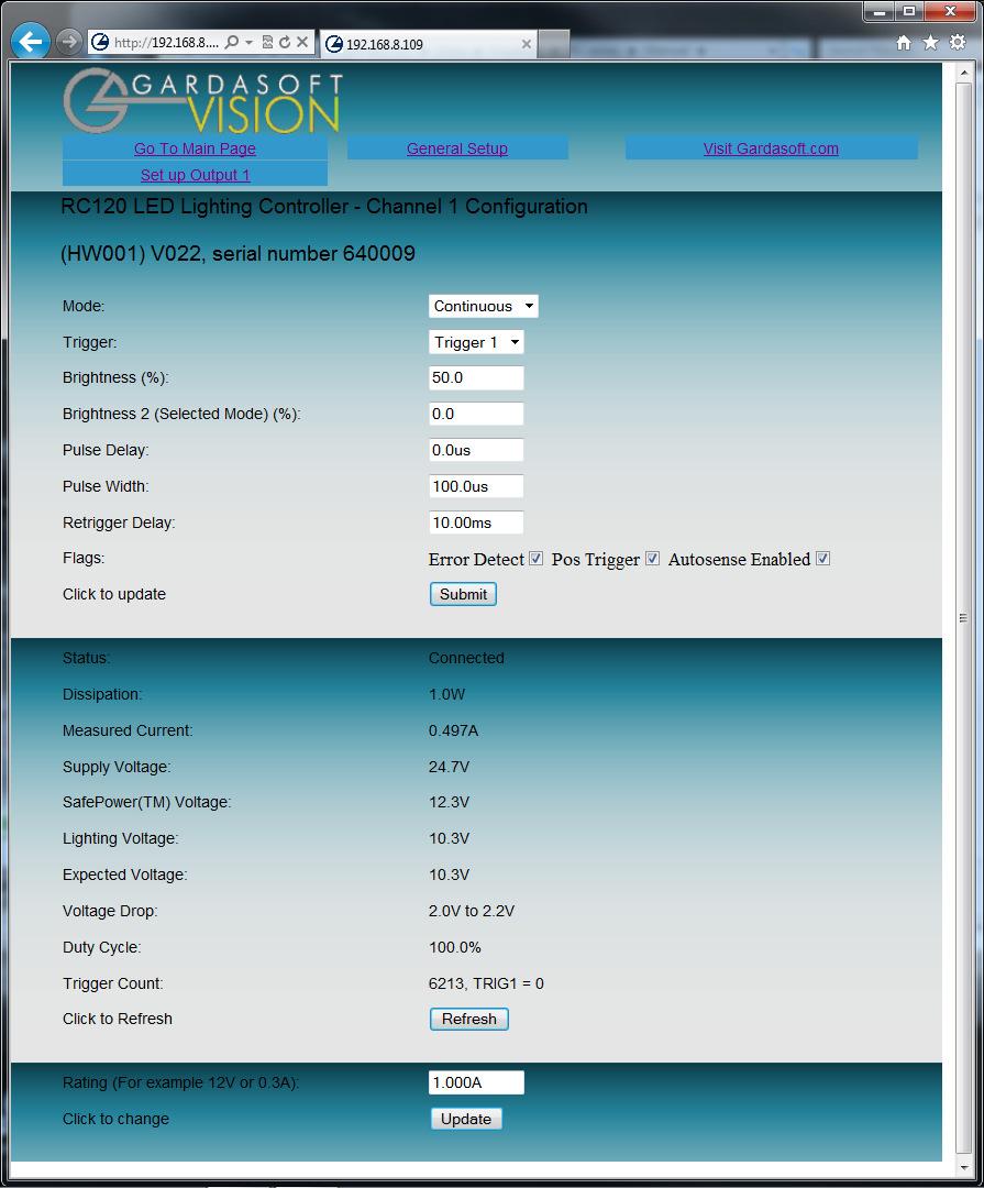
30 General Setup Page The General Configuration page allows the webpage protection password to be set or cleared and the internal trigger to be set up. Also any Ethernet command from Section 11 can be entered Configuration Page The configuration page allows all the output parameters to be set up. Pressing the Submit button updates the RC120 configuration and save the changes to non-volatile memory. The current rating for the light can be changed. Use this with care. Some measured voltages and the actual output current are displayed on this page.
31 31
32 32 11 Command Configuration (RC120) The RC120 can be configured via the Ethernet connection using UDP or TCP/IP. A Configuration Program with source code is available for download from Ethernet Communication (RC120) Commands sent from a PC in UDP and TCP packets should be sent to destination port Replies will be sent back to the source port (so in the reply the source and destination ports will be swapped). A TCP/IP connection timeouts and closes if it is idle for more than 10 seconds. The host must send regular commands or keepalive packets to keep the link open. A carriage return (ASCII 13) character should be sent to terminate the command line, in case multiple TCP packets get joined together Command Structure Communication consists of commands sent by the host (controlling PC). The command and any reply output generated by the command is returned in reply UDP or TCP/IP packets followed by <LF> <CR>. The last character sent is a > prompt ( greater than symbol). Once this is received, the host knows that the command has been completed. For example when sending the VR command the reply might be: Where VRRC120 (HW001) V002<LF><CR>> The red text is the command reflected back The green text is the reply data The blue text is control codes ASCII 10, ASCII 13 The black text is the prompt > If there is an error (see error codes below) then a typical reply is: VTErr 2<LF><CR>> It is recommended that the host waits for the > symbol before sending the next command. UDP communications are not guaranteed to arrive, so the host software must be able to cope with lost messages. Using the GT command, a host can request that a message is sent to it whenever an error occurs. Several commands can be put into one command line by separating them by a semicolon ( ; ).The RC120 send any replies to the commands followed by a > character to show that the command line has completed.
33 All commands comprise a code of two letters followed by any optional parameters. All spaces in the commands are ignored. Numeric parameters are separated by a comma (, ). For a parameter which is a time period the default units are milliseconds. s, ms or us can be added to the end of the number to indicate seconds, milliseconds or microseconds. For currents, A or ma can be added to indicate amps or milliamps. The default is amps. Note that parameters are in USA/UK format so that a half is written 0.5 not 0,5 For example: 33 Parameter Meaning milliseconds 200us 200 microseconds 0.1s 0.1 seconds 100ma 100mA 2.45A 2.45A mA or 2.3A The command codes and their meaning are described below. The upper case commands are shown, followed by lower case letters denoting the numeric argument. If a command is invalid in any way an error message is returned before the <LF> <CR> > reply. Error number Err 1 Err 2 Err 3 Err 4 Err 5 Reason A parameter value is invalid Command not recognised Numeric value is wrong format Wrong number of parameters (This is only a warning) The command is accepted but a timing parameter was out of range and has been adjusted to a valid value.
34 34 Any changes made using Ethernet commands are not saved permanently until the AW command has been issued General Commands Report the version of firmware running in the RC120 This command returns the firmware version. For example: VR RC120 (HW001) V001 Set the rating of a light This command sets the current or voltage rating for a light. If a current rating is being set, then the voltage rating value should be 0. VL1,v,c Where: v = voltage rating (0 or 12 to 24) c = current rating (0 or 10mA to 2A) Set continuous mode The output is set to continuous mode at a percentage of full brightness. RS1,s Where: s = setting in percent (s = 0 to 100) Set pulse mode The output can be set up to pulse on a trigger input. The delay from trigger to the start of the pulse, the length of the pulse and the brightness are configurable. An error is generated if the brightness setting requires a current greater than the maximum current output or if the combination of pulse width and setting is not allowed. If the retrigger time is omitted, then the minimum allowed retrigger time is set. RT1,p,d,s RT1,p,d,s,r Where: p = pulse width in milliseconds (0.1 to 999) d = delay from trigger to pulse in milliseconds (0 to 999) s = setting in percent (s = 0 to 999) r = retrigger delay. This parameter is optional. Set switched mode The output is set to switched mode at a percentage of full brightness. RW1,s Where: s = setting in percent (s = 0 to 100)
35 Set the Trigger Input This command sets which input is used for pulse and switch output modes. RP1,p Where: p = trigger input (1 or 2) Set the Option Flags RE1,m Where: m = flags: bit 0 Not used bit 1 = 0 E flag set (error detection enabled) 1 E flag cleared (error detection disabled) bit 2 = 0 P flag set (positive triggers) 1 P flag cleared (negative triggers) bit 3 = 0 S flag set (SafeSense enabled) 1 S flag cleared (SafeSense disabled) Set Internal Trigger Enable or disable the internal trigger. When enabled, all outputs are triggered simultaneously using an internal trigger signal. This setting can be saved to non-volatile memory using the AW command. TT0 Disable internal trigger TT1 Enable internal trigger (uses previously set period) TT1,p Enable internal trigger and set the period Where: p= period of the triggers in milliseconds For example: TT1,200 TT1,500US Save the settings to memory Set the internal trigger to 200ms (5Hz) Set the internal trigger to 500us (2KHz) AW Once the settings are saved to memory they are then retained when the unit is switched off. If this is not done, changes to the settings are volatile, and if the unit is switched off they revert to those in force when the last AW command was issued. Clear Configuration CL Clears the configuration and lighting ratings and sets the output to 50% continuous operation. The results of the VL, RS, RW, RU, RT, RE, RP, TT, AW commands are all cleared. 35
36 36 Show Configuration ST This command shows the configuration of the controller. A typical output for a RC1XX controller is: CH1,MD0,S50.0,0.0,DL1.000ms,PU1.000ms,RT0.0us,IP1,FL0,CS0.000A,RA0.000A Where: CH Channel number (RC1xx units have 1 channel) MD Mode: 0 = continuous, 1 = pulse, 2 = switched, 3 = select S Brightness percentage settings: 1 st setting used in all modes 2 nd setting only used for select mode DL Pulse delay PU Pulse width RT Retrigger delay IP Input Trigger (set using the RP command) FL Flags (set using the RE command) CS Current rating of the light (after SafeSense has successfully completed sensing the light) RA Configured voltage or current rating of the light (set using VL command) When using Ethernet, use the following forms of the ST command as the command above will generate more data than can be sent in a reply packet. ST0 Reports the general settings. Typical output is: TM 1, TP 20.00ms ST Reports output settings. Simulate an Input Trigger TR1 Simulates a trigger pulse. If the unit is in pulse mode it pulses the output once and shows PUL on the display. Enable Ethernet Messages GTm m = 0 to disable Ethernet messages = 1 to enable Ethernet messages When Ethernet messages are enabled, any error reports are sent to the most recent UDP or TCP address from which a command has been received. Messages are of the form: Evtc,e Where c 1 for events concerning the lighting output, else 0 v event value, see appendix E
37 Clear any Errors GR If Ethernet messages are not enabled, the last event or error number can be read by this command. Any error displayed on the unit is cleared, so if there was a lighting error, the RC1XX resumes auto-sensing on that channel. The reply is in the same form as the GT command above. If there are no outstanding events or errors, then only the prompt > is returned. Set/Clear the Webpage Password EY EY asc1, asc2, asc3, asc4, asc5, asc6 This command sets the password required to access the webpages. If EY is entered on its own then the password is cleared. There are six optional parameters, which are decimal ASCII values for a password from one to six letters. A value of 65 is A, 66 is B, etc to 90 is Z. Disable Keypad KBd,c d = 0 Enable keypad d = 1 Disable keypad, but allow unlock code d = 2 Disable keypad, disable unlock code c Unlock code In some applications it may be necessary to lock the keypad so that un-authorised operators cannot change the settings. A unlock code can be set. This can be used as a low-security way of allowing trusted users to unlock the keypad. Ethernet commands and the web pages still work. The setting of this command is restored after a power cycle. 37
38 Command Summary Command Example Effect AW AW Save changes CL CL Clear configuration GT GT1 Enable Ethernet messages GR GR Clear any error condition. EY EY65,66 Set webpage password to AB VR VR Read the firmware version VL VL1,0,0.5 Set the light rating to 0.5A RS RS1,65 Set unit to 65% brightness continuous RW RW1,50 Set unit to 50%, switch mode RU RU1,75,25 Set unit to selected mode at 75% and 25% RT RC1,3,4,50 Set unit to 3ms pulses, delayed by 4ms, at 50% brightness RE RE1,6 Set unit to ignore lighting errors and make its trigger input active low. TT TT1,1ms Set internal triggers every 1ms KB KB1,23 Disable the buttons on the front panel. Set the unlock code to 23. TR TR1 Generate one Trigger pulse ST ST Show Configuration Status
39 A. Specification RC100 RC120 User interface Pushbutton Ethernet and Pushbutton Output channel Output current Output power Trigger input One constant current output with SafeSense TM Up to 1.0A continuous or 1.0A pulsed Max 25W 39 Up to 1.2A continuous or 2.0A pulsed Smart input compatible with 3V-24V, TTL, NPN, and PNP. Input impedance (nom): 50Kohm Pulse timing From 100µs to 100ms in steps of 100µs Delay from trigger to pulse Timing repeatability (Delay) Timing repeatability (Pulse width) Switch mode latency Trigger rate Output voltage Supply voltage Dimensions Weight Mounting Operating temperature: Humidity: From 2µs to 100ms in steps of 100µs +/-5µs (Delay + Pulse up to 60ms) Otherwise +/-50µs +/-0.1µs (Delay + Pulse up to 1ms) +/-5µs (Delay + Pulse from >1ms to 60ms) Otherwise +/-50µs Maximum 100us Maximum 100Hz 0V to 32V Regulated 24VDC+/-10% A SELV power supply is required. 101mm long by 35mm wide by 120mm high (excluding DIN fixing) 175g DIN rail mount as standard 5 to 50 o C Up to 95% non-condensing
40 40 B. Restrictions The following timings and restrictions are applied when commands are entered. Exceeding these values will cause an error to be returned. The keypad interface prevents invalid values being entered. B.1 Continuous Mode The maximum continuous output current is 1A (RC100), 1.2A (RC120). B.2 Switched Mode The maximum delay from a trigger input changing to the output current being turned on or off is 100us. The maximum output current limit is the same as Pulse mode. B.3 Pulse Mode The maximum pulsed output current is 1.2A (RC100), 2A (RC120). For high current pulses the following limits apply: When a delay of 0us is set, the actual delay will be about 4us. For pulse widths of 100us the output voltage and current cannot be measured. Because of this, fault detection is disabled and the following restrictions apply: For pulse currents greater than 0.5A, the duty cycle is restricted to 1% For pulse currents less than or equal to 0.5A, the duty cycle restricted to 10%
41 C. Error Codes 41 Error number Err 1 Err 2 Err 3 Err 4 Err 5 Err 19 Err 8, 12 Err 9, 20 Err 21, Err 22, Err 23 Err 27 PO, Err 34, Err 47 OP, Err 35 OP, Err 43 SH, Err 36 SH, Err 42 HI, Err 37 LO, Err 38 Err 39 Reason A parameter value is invalid Command not recognised Numeric value is wrong format Wrong number of parameters This is a warning, not an error. One of the parameters is out of range. The value of the parameter has been adjusted. For example, sending an RT command with a delay of 0 gets a reply of Err 5. The command is accepted but the delay is set to the minimum allowed value. A light has been connected to a channel but no rating has been set. EEPROM corrupt. The configuration has been cleared. Couldn t save settings to EEPROM. Sensing error. See section 6.6. Can t read Ethernet settings from EEPROM, so these may be incorrect. Internal power dissipation is too high. Output turned off. Output current to lighting is too low. The requested output current requires too high a voltage. The output is short circuit. The output current is too high. The voltage required for the lighting has increased too much. Check for ageing of the lighting or a failed LED. The voltage required for the lighting has decreased too much. Check for ageing of the lighting or a failed LED. Internal protection has prevented SafePower voltage going too high. Err 46 The channel power output is greater than the maximum allowed 30W. Any other errors are internal errors.
42 42 D. Fatal Error Codes Error number FAt, Err 44 FAC, Err 40, Err 41, Err 45 FAS, Err 47 Reason The RC1XX is too hot. The RC1XX has a thermal cutout which operates around 65 O C to 70 O C, depending on conditions. Unit is outputting more current than expected. Internal protection has activated to prevent too much heat in the output driver. E. Event Codes Event messages are sent by Ethernet when a light is connected or an error occurs. The format of these is Evt<channel>,<event code>; These event messages are only sent after the GT1 command has been sent. Event number Reason 1 to 127 An error has occurred. The error code is given by the event number. 128 A light has been connected and is working. 129 A light has been connected but doesn t have a current or voltage rating. 130 Over temperature error occurred ( FAT) 131 Over current error occurred (FAC) 132 An error has occurred while autosensing the rating of a light. 138 SafePower trainup has completed. 139 SafePower trainup has failed or been cancelled. 140 In switch output mode, the light has been turned off because the duty cycle is too high.
43 Gardasoft Traffic Strobe Lights The products available at the time of writing include the following. Other products are also available. See for details of the current range. 43 VTR1 Range Up to 300W per steradian output power Infra-red 740nm, 850nm, 940nm and White options Ethernet and RS232 options Trigger input and trigger output options 12 degree and 30 degree beam angle options VTR2 Range Up to 3000W per steradian output power Infra-red 740nm, 850nm, 940nm and White options Ethernet, RS232 and RS422 options Trigger input and trigger output options 12 degree and 30 degree beam angle options VTR4 Range Up to 6000W per steradian output power Infra-red 850nm and White options (others on request) Ethernet and RS232 options Trigger input and trigger output options 12, 14 degree and 28 degree beam angle options VTR6 Range Up to 9000W per steradian output power Infra-red 850nm and White options (others on request) Ethernet and RS232 options Trigger input and trigger output options 12, 14 degree and 28 degree beam angle options
44 44 Gardasoft LED Lighting Controllers The products available at the time of writing include the following. Other products are also available. See for details of the current range. RT/RC Range 1, 2, 4 or 8 output channels 2A and 20A maximum current version available 1, 2, 4 or 8 trigger inputs SafePower TM and SafeSense TM Front panel, RS232 or Ethernet configuration Fast pulsing option RC100 RC120 RT RT RT RT200F-20 RT220F-20 RT260F-20 RT RT420F-20 RT820F-20 RT860F-20 Lighting controller: 1 channel up to 1A pulsing, front panel Lighting controller: 1 channel up to 2A pulsing, front panel and Ethernet Lighting controller: 2 channels up to 20A pulsing, front panel Lighting controller: 2 channels up to 20A pulsing, Ethernet Lighting controller: 2 channels up to 20A pulsing, RS232 Lighting controller: 2 channels up to 20A fast pulsing, front panel Lighting controller: 2 channels up to 20A fast pulsing, Ethernet Lighting controller: 2 channels up to 20A fast pulsing, RS232 Lighting controller: 4 channels up to 20A pulsing, Ethernet Lighting controller: 4 channels up to 20A fast pulsing, Ethernet Lighting controller: 8 channels up to 20A fast pulsing, Ethernet Lighting controller: 8 channels up to 20A fast pulsing, RS232 PP Range 2, 4 or 8 output channels up to 20A each 2, 4 or 8 trigger inputs SafeSense TM option Front panel, RS232 or Ethernet configuration Fast pulsing option CC320 Controller Machine Vision Timing Controller 8 digital inputs 8 digital outputs 1 or 2 wire Encoder input Very flexible operation Ethernet control Front panel configuration
LED Lighting Controller User Manual
 NL-200, NL-220, NL-220F LED Lighting Controller User Manual P/N 84-100022 Rev A 1 Disclaimer Except as prohibited by law: All hardware, software and documentation is provided on an as is basis. It is essential
USER MANUAL. PP500, PP520, PP500F, PP520F LED Lighting Controllers. Revision 05
 USER MANUAL PP500, PP520, PP500F, PP520F LED Lighting Controllers Revision 05 Gardasoft Vision Ltd Units 1 & 2, Castle Acres, Elsworth Cambridge, CB23 4JQ. UK Tel: +44 1954 200343 Fax: +44 1954 204343
The Practical use of LED Light Controllers within Machine Vision systems
 LED Light Controllers Technology overview The Practical use of LED Light Controllers within Machine Vision systems The successful, cost-effective application of a Machine Vision system is often dependent
Metaphase ULC-2. Technologies ULC. Metaphase. Technologies Version 7.X August 2015 USER MANUAL. metaphase-tech.com. pg. 1
 ULC Version 7.X August 2015 USER MANUAL pg. 1 Overview Universal LED Controller () provides independent true constant-current or voltage control of two LED loads from 0.02 to 4 Amps continuous (DC) with
The Practical use of LED Light Controllers within Machine Vision systems
 The Practical use of LED Light Controllers within Machine Vision systems The successful, cost-effective application of a Machine Vision system is often dependent on the interplay of many individual elements,
Metaphase ULC-2. Technologies ULC. Metaphase. Technologies Version 6.2 June 12, 2013 USER MANUAL. metaphase-tech.com. pg. 1
 ULC Version 6.2 June 12, 2013 USER MANUAL pg. 1 Overview Universal LED Controller () provides independent true constant-current or voltage control of two LED loads from 0.02 to 4 Amps continuous (DC) with
Modular Metering System ModbusTCP Communications Manual
 Modular Metering System Manual Revision 7 Published October 2016 Northern Design Metering Solutions Modular Metering System ModbusTCP 1 Description The multicube modular electricity metering system simultaneously
Smartek LED Strobe Controller Family
 Smartek LED Strobe Controller Family User Manual Document version 1.2, last changed: IPSC1 IPSC2 IPSC4 Table of Contents 1.Overview...1 1.1.Precautions...1 1.2.Description...2 1.3.Family models...2 2.IPSC1...3
Mate Serial Communications Guide This guide is only relevant to Mate Code Revs. of 4.00 and greater
 Mate Serial Communications Guide This guide is only relevant to Mate Code Revs. of 4.00 and greater For additional information contact matedev@outbackpower.com Page 1 of 20 Revision History Revision 2.0:
RF Wireless Serial Device Server
 RF-SDS RF Wireless Serial Device Server The RF-SDS subassembly is a radio transceiver acting as a Serial Device Server, which externally connects a remote serial RF transceiver to an Ethernet network (TCP/IP).
Mounting instruction and operating manual. Access Point (UK) HmIP-HAP-UK
 HmIP-HAP-UK") Mounting instruction and operating manual Access Point (UK) HmIP-HAP-UK Package contents Quantity Description 1 Homematic IP Access Point (UK) 1 Plug-in mains adapter 1 Network cable 2 Screws 2 Plugs 1
Mounting instruction and operating manual Access Point (UK) HmIP-HAP-UK Package contents Quantity Description 1 Homematic IP Access Point (UK) 1 Plug-in mains adapter 1 Network cable 2 Screws 2 Plugs 1
VersaMax Mixed Discrete / High-Speed Counter Module
 Product Description The VersaMax Mixed Discrete High-Speed Counter (HSC) module,, has twenty 24VDC positive-logic type inputs and twelve positive-logic 24VDC 0.5Amp outputs. In its default configuration,
MD04-24Volt 20Amp H Bridge Motor Drive
 MD04-24Volt 20Amp H Bridge Motor Drive Overview The MD04 is a medium power motor driver, designed to supply power beyond that of any of the low power single chip H-Bridges that exist. Main features are
Tarocco Closed Loop Motor Controller
 Contents Safety Information... 3 Overview... 4 Features... 4 SoC for Closed Loop Control... 4 Gate Driver... 5 MOSFETs in H Bridge Configuration... 5 Device Characteristics... 6 Installation... 7 Motor
VersaMax Mixed Discrete / High-Speed Counter Module
 Product Description The VersaMax Mixed Discrete High-Speed Counter module, IC200MDD841, has twenty 24VDC positive-logic type inputs and twelve positive-logic 24VDC 0.5Amp outputs. In its default configuration,
WTPCT-M. eeder. Pulse Counter/Timer Module. Technologies FEATURES SPECIFICATIONS DESCRIPTION. Weeder Technologies
 eeder Technologies 90-A Beal Pkwy NW, Fort Walton Beach, FL 32548 www.weedtech.com 850-863-5723 Pulse Counter/Timer Module FEATURES Reads frequency from 0.50000 to 1,400,000 Hz using 5 digit resolution
High Current DC Motor Driver Manual
 High Current DC Motor Driver Manual 1.0 INTRODUCTION AND OVERVIEW This driver is one of the latest smart series motor drivers designed to drive medium to high power brushed DC motor with current capacity
WTDIN-M. eeder. Digital Input Module. Technologies FEATURES SPECIFICATIONS DESCRIPTION. Weeder Technologies
 eeder Technologies 90-A Beal Pkwy NW, Fort Walton Beach, FL 32548 www.weedtech.com 850-863-5723 Digital Input Module FEATURES 8 wide-range digital input channels with high voltage transient protection.
DRG-Series. Digital Radio Gateway. Tait P25 CCDI Tier-2 (TM9400 Series Mobile Radio) Digital Radio Supplement
 Digital Radio Supplement") DRG-Series Digital Radio Gateway Tait P25 CCDI Tier-2 (TM9400 Series Mobile Radio) Digital Radio Supplement DRG-Series Digital Radio Gateway Tait P25 CCDI Tier-2 (TM9400 Series Mobile Radio) Digital Radio
DRG-Series Digital Radio Gateway Tait P25 CCDI Tier-2 (TM9400 Series Mobile Radio) Digital Radio Supplement DRG-Series Digital Radio Gateway Tait P25 CCDI Tier-2 (TM9400 Series Mobile Radio) Digital Radio
DRG-Series. Digital Radio Gateway. Hytera DMR USB Donor (Tier-2) Digital Radio Supplement
 Digital Radio Supplement") DRG-Series Digital Radio Gateway Hytera DMR USB Donor (Tier-2) Digital Radio Supplement DRG-Series Digital Radio Gateway Hytera DMR USB Donor (Tier-2) Digital Radio Supplement 2015 Omnitronics Pty Ltd.
DRG-Series Digital Radio Gateway Hytera DMR USB Donor (Tier-2) Digital Radio Supplement DRG-Series Digital Radio Gateway Hytera DMR USB Donor (Tier-2) Digital Radio Supplement 2015 Omnitronics Pty Ltd.
F2A3X Frequency to Analog Converter Module
 the professional s choice F2A3X Frequency to Analog Converter Module Instruction Manual MONARCH INSTRUMENT 15 Columbia Drive Amherst, NH 03031 USA Phone: (603) 883-3390 Fax: (603) 886-3300 E-mail: support@monarchinstrument.com
MADEinUSA OPERATOR S MANUAL. RS232 Interface Rev. A
 MADEinUSA OPERATOR S MANUAL RS232 Interface 92-3006 Rev. A www.iradion.com Iradion Laser, Inc. 51 Industrial Dr. N. Smithfield, RI 02896 (410) 762-5100 Table of Contents 1. Overview... 2 2. Equipment Required...
TT-208. User s Manual. 300Mps 5.8 GHz. IP Camera Wireless Transmission Kit
 TT-208 300Mps 5.8 GHz IP Camera Wireless Transmission Kit User s Manual V1.0 02 / 2014 Welcome Thank you for purchasing the TT-208 Wireless Transmission Kit for IP Cameras. This user s manual is designed
Ultrasonic Multiplexer OPMUX v12.0
 Przedsiębiorstwo Badawczo-Produkcyjne OPTEL Sp. z o.o. ul. Morelowskiego 30 PL-52-429 Wrocław tel.: +48 (071) 329 68 54 fax.: +48 (071) 329 68 52 e-mail: optel@optel.pl www.optel.eu Ultrasonic Multiplexer
WTDOT-M. eeder. Digital Output Module. Technologies FEATURES SPECIFICATIONS DESCRIPTION. Weeder Technologies
 eeder Technologies 90-A Beal Pkwy NW, Fort Walton Beach, FL 32548 www.weedtech.com 850-863-5723 Digital Output Module FEATURES 8 high-current open-collector output channels with automatic overload shutdown.
AT-XTR-7020A-4. Multi-Channel Micro Embedded Transceiver Module. Features. Typical Applications
 AT-XTR-7020A-4 Multi-Channel Micro Embedded Transceiver Module The AT-XTR-7020A-4 radio data transceiver represents a simple and economical solution to wireless data communications. The employment of an
UCP-Config Program Version: 3.28 HG A
 Program Description HG 76342-A UCP-Config Program Version: 3.28 HG 76342-A English, Revision 01 Dev. by: C.M. Date: 28.01.2014 Author(s): RAD Götting KG, Celler Str. 5, D-31275 Lehrte - Röddensen (Germany),
DRG-Series. Digital Radio Gateway. Motorola MotoTRBO DMR. Interfacing Omnitronics DRG with Motorola MotoTRBO DMR Digital Radios
 DRG-Series Digital Radio Gateway Motorola MotoTRBO DMR Interfacing Omnitronics DRG with Motorola MotoTRBO DMR Digital Radios Digital Radio Supplement DRG-Series Supplement Interfacing Omnitronics DRG with
Universal-Transducer Multi-E11-MU
 Universal-Transducer Multi-E11-MU Safety Informations Observe instructions! The device described in these instructions shall only be installed by a qualified electrician according to both EN 50110-1/-2
INSTALLATION MANUAL. Model: Smart Analyzer Manufacturer: Smart Impulse. Power meter with consumption breakdown by use 03/12/13
 INSTALLATION MANUAL Model: Smart Analyzer Manufacturer: Smart Impulse Power meter with consumption breakdown by use 03/12/13 Table of contents Table of contents... 2 1. Introduction... 3 2. Installation
AW2400iTR USER S MANUAL 2.4 GHz Indoor Wireless Ethernet Radio
 USER S MANUAL 2.4 GHz Indoor Wireless Ethernet Radio Industrial-grade, long-range wireless Ethernet systems AvaLAN W I R E L E S S Thank you for your purchase of the AW2400iTR Indoor Wireless Ethernet
AR-DN-RS232. An-10 / Rapid RS232 Interface. Product Guide. Overview. Features
 AR-DN-RS232 An-10 / Rapid RS232 Interface Product Guide Overview The AR-DN-RS232 is a device that is used as a 2 way gateway between third party systems and the CP An-10 or Rapid lighting control systems
G3P-R232. User Manual. Release. 2.06
 G3P-R232 User Manual Release. 2.06 1 INDEX 1. RELEASE HISTORY... 3 1.1. Release 1.01... 3 1.2. Release 2.01... 3 1.3. Release 2.02... 3 1.4. Release 2.03... 3 1.5. Release 2.04... 3 1.6. Release 2.05...
Data Acquisition Modules/ Distributed IO Modules
 User Manual Data Acquisition Modules/ Distributed IO Modules Future Design Controls, Inc. 7524 West 98 th Place / P.O. Box 1196 Bridgeview, IL 60455 888.751.5444 - Office: 888.307.8014 - Fax 866.342.5332
I-7088, I-7088D, M-7088 and M-7088D User Manual
 I-7088, I-7088D, M-7088 and M-7088D User Manual I-7000 New Features 1. Internal Self Tuner 2. Multiple Baud Rates 3. Multiple Data Formats 4. Internal Dual WatchDog 5. True Distributed Control 6. High
HOMANN DESIGNS. DigiSpeed. Instruction manual. Version 1.0. Copyright 2004 Homann Designs.
 HOMANN DESIGNS DigiSpeed Instruction manual Version 1.0 Copyright 2004 Homann Designs http://www.homanndesigns.com Table of Contents Introduction...3 Features...3 DigiSpeed Operation Description...5 Overview...5
DRG-Series. Digital Radio Gateway. Kenwood NXDN Donor Radio (Tier-2) Interfacing Omnitronics DRG with Kenwood NXDN Donor Digital Radios (Tier-2)
 Interfacing Omnitronics DRG with Kenwood NXDN Donor Digital Radios (Tier-2)") DRG-Series Digital Radio Gateway Kenwood NXDN Donor Radio (Tier-2) Interfacing Omnitronics DRG with Kenwood NXDN Donor Digital Radios (Tier-2) Digital Radio Supplement DRG-Series Supplement Kenwood NXDN
DRG-Series Digital Radio Gateway Kenwood NXDN Donor Radio (Tier-2) Interfacing Omnitronics DRG with Kenwood NXDN Donor Digital Radios (Tier-2) Digital Radio Supplement DRG-Series Supplement Kenwood NXDN
EVDP610 IXDP610 Digital PWM Controller IC Evaluation Board
 IXDP610 Digital PWM Controller IC Evaluation Board General Description The IXDP610 Digital Pulse Width Modulator (DPWM) is a programmable CMOS LSI device, which accepts digital pulse width data from a
HAWK5000 Operators Manual
 HAWK5000 Operators Manual Keison Products P.O. Box 2124, Chelmsford CM1 3UP, England Tel: +44 (0) 1245 600560 Fax: +44 (0) 1245 600030 Email: sales@keison.co.uk www.keison.co.uk KANE INTERNATIONAL LIMITED
BusWorks 900EN Series Modbus TCP/IP 10/100M Industrial Ethernet I/O Modules
 BusWorks 900EN Series Modbus TCP/IP 10/100M Industrial Ethernet I/O Modules Six Differential Current Inputs Six Differential Voltage Inputs USER S MANUAL ACROMAG INCORPORATED Tel: (248) 295-0880 30765
1. Function. Universal dimming actuator REG-K/2x230/ 300 W. Universal dimming actuator REG-K/230/ 500 W. Universal dimming actuator REG-K/230/ 1000 W
 L L N N on error RUN 1 2 3 4 KNX EIB 1 1 1 1 Chapter 9: Dimming actuators/control units Chapter 9:Dimming actuators/control unitsart. no.6493xxas of 10/079.2Universal dimming actuators Universal dimming
SMARTALPHA RF TRANSCEIVER
 SMARTALPHA RF TRANSCEIVER Intelligent RF Modem Module RF Data Rates to 19200bps Up to 300 metres Range Programmable to 433, 868, or 915MHz Selectable Narrowband RF Channels Crystal Controlled RF Design
Channel processing equipment
 Channel processing equipment 1. Product description DVB-T/T2 to DVB-C transmodulator is a 4 channel DVB-T/T2 to DVB-C transmodulator (in text - module). The module uses transparent transmodulation - passing
RC-WIFI CONTROLLER USER MANUAL
 RC-WIFI CONTROLLER USER MANUAL In the rapidly growing Internet of Things (IoT), applications from personal electronics to industrial machines and sensors are getting wirelessly connected to the Internet.
PROMUX Distributed MODBUS I/O Modules Catalog and Design Guide
 PROMUX Distributed MODBUS I/O Modules Catalog and Design Guide 14/11/2006 V10 P.O.Box 24 Stanfield 3613 SOUTH AFRICA Tel: +27 (031) 7028033 Fax: +27 (031) 7028041 Email: proconel@proconel.com Web: www.proconel.com
Models included: GEO EDGE
 Models included: GEO EDGE Printed in USA 12/04 P/N 118000 rev. A WARNING... Not To Be Used for Personnel Protection Never use this product as a sensing device for personnel protection. Doing so could lead
SKIM USER S GUIDE SMART KAN INTERFACE MODULE 2 & 8 I/O
 SKIM USER S GUIDE SMART KAN INTERFACE MODULE 2 & 8 I/O Kongsberg Automotive: Christopher Martin Road Basildon, Essex England SS143ES Tel: +44(0)1268 522861 Fax: +44(0)1268 282994 90, 28e Rue Grand-Mere
WPE 48N USER MANUAL Version1.1
 Version1.1 Security instructions 1. Read this manual carefully. 2. Follow all instructions and warnings. 3. Only use accessories specified by WORK PRO. 4. Follow the safety instructions of your country.
HB-25 Motor Controller (#29144)
") Web Site: www.parallax.com Forums: forums.parallax.com Sales: sales@parallax.com Technical: support@parallax.com Office: (916) 624-8333 Fax: (916) 624-8003 Sales: (888) 512-1024 Tech Support: (888) 997-8267
Web Site: www.parallax.com Forums: forums.parallax.com Sales: sales@parallax.com Technical: support@parallax.com Office: (916) 624-8333 Fax: (916) 624-8003 Sales: (888) 512-1024 Tech Support: (888) 997-8267
EE 314 Spring 2003 Microprocessor Systems
 EE 314 Spring 2003 Microprocessor Systems Laboratory Project #9 Closed Loop Control Overview and Introduction This project will bring together several pieces of software and draw on knowledge gained in
U S E R S M A N U A L
 U S E R S M A N U A L T H E R M O R E G U L A T O R T R 5 0 0 / T R 5 0 1 S E R I E S HUNDREDTHS VERSION ENGLISH V.1.2 TABLE OF CONTENTS -1- Introduction... page 2-2- Technical specifications -3- Description
maxon document number:
 maxon document number: 791272-04 1 Table of contents... 2 2 Table of figures... 3 3 Introduction... 4 4 How to use this guide... 4 5 Safety Instructions... 5 6 Performance Data... 6 6.1 Motor data... 6
SilverMax Datasheet. QuickSilver Controls, Inc. NEMA 23 Servomotors.
 SilverMax Datasheet NEMA 23 Servomotors QuickSilver Controls, Inc. www.quicksilvercontrols.com SilverMax Datasheet - NEMA 23 Servomotors 23 Frame Sizes: 23-3, 23-5, 23H-1, 23H-3, 23H-5 / Series: E, E3,
Figure 1. DMC 60 components.
 1300 Henley Court Pullman, WA 99163 509.334.6306 www.digilentinc.com DMC 60 Reference Manual Revised November 15, 2016 This manual applies to the DMC 60 rev. A Overview The DMC 60 is an electronic speed
Brushless DC Motor Controller Specification Assemblies 025F0248
 Brushless DC Motor Controller Specification Assemblies 025F0248 600A1099 Rev. B April 4 th, 2014 Revision History EC Date Description Rev EC54318 09/03/13 Initial Release A EC58093 04/04/14 Added cap discharge
Connecting Mains Electrical Power
 Tide Level Monitoring Instrumentation The following documentation details the electrical installation for the tide level monitoring instrumentation and also a summary of the logger configurations required
Smart-house Dimmer Power dimmer up to 500W Type SH2D500W230
 Smart-house Dimmer Power dimmer up to 500W Type SH2D500W230 Universal dimmer switch for R, L, C up to 500W and LED loads Automatic load detection for L, R, C loads Integrated heat sink for temperature
Jaguar Motor Controller (Stellaris Brushed DC Motor Control Module with CAN)
") Jaguar Motor Controller (Stellaris Brushed DC Motor Control Module with CAN) 217-3367 Ordering Information Product Number Description 217-3367 Stellaris Brushed DC Motor Control Module with CAN (217-3367)
Jaguar Motor Controller (Stellaris Brushed DC Motor Control Module with CAN) 217-3367 Ordering Information Product Number Description 217-3367 Stellaris Brushed DC Motor Control Module with CAN (217-3367)
PACSystems* RX3i IC695MDL664-BB
 Important Product Information April 2015 PACSystems* RX3i Digital Input Module with Diagnostics 16-Channel 1 2 3 4 5 6 7 8 OK 9 10 11 12 13 14 15 16 S1 S2 IC695MDL664 I1 I2 I3 I4 I5 I6 I7 I8 I9 I10 I11
ASTi SYNAPSE Remote Control Guide Document: DOC-01-SYN-RC-1
 ASTi SYNAPSE Remote Control Guide Document: DOC-01-SYN-RC-1 Advanced Simulation Technology inc. 500A Huntmar Park Drive, Herndon, Virginia, 20170 USA Revision B (Oct., 2011) Product Name: ASTi Synapse
Table of Contents. HWIO-Gateway User Manual
 User Manual HWIO-Gateway INUX AB Katrinedalsg. 3, 504 51 Borås http://www.inux.se Copyright 2009 Uppdaterad 2010-01-12 Copyright 2009 INUX AB 1 Table of Contents 1. Product overview...3 2. License...3
POWER AMPLIFIERS 4 QUADRANTS 3x500 VA to 3x1500 VA - THREE-PHASES
 PERFORMANCES High accuracy High stability Fast transients High inrush current facilities Wide bandwidth Very low distortion Quadrant change without transition Very low output impedance Low noise RS232
BMS BMU Vehicle Communications Protocol
 BMS Communications Protocol 2013 Tritium Pty Ltd Brisbane, Australia http://www.tritium.com.au 1 of 11 TABLE OF CONTENTS 1 Introduction...3 2 Overview...3 3 allocations...4 4 Data Format...4 5 CAN packet
Multifunctional counter tico 772/773/774
 Universally applicable as a tachometer, timer, shift counter, batch counter Easy to operate Four different backlight colours Intensity of backlighting can now be adjusted Large, clearly readable 48 x 48
PROMUX Distributed MODBUS I/O Modules Catalog and Design Guide
 PROMUX Distributed MODBUS I/O Modules Catalog and Design Guide 12/03/2012 V11.0 P.O.Box 164 Seven Hills 1730 NSW AUSTRALIA Tel: +61 2 96248376 Fax: +61 2 9620 8709 Email: proconel@proconel.com Web: www.proconel.com
8000 SERIES PRECISION MULTIMETER VERIFICATION AND ADJUSTMENT GUIDE
 8000 SERIES PRECISION MULTIMETER VERIFICATION AND ADJUSTMENT GUIDE TRANSMILLE LTD. Version 1.1 : Apr 2015 TABLE OF CONTENTS PREPARING FOR CALIBRATION... 4 INTRODUCTION... 4 CALIBRATION INTERVAL SELECTION...
LVCSi Continuous Vertical Level Sensor with Integrated Display
 Table of Contents 1. Introduction... 3 2. Main Features... 4 2.1 Sensor Inputs... 4 2.2 Display... 5 2.3 Analogue Outputs... 6 2.4 Digital Outputs... 7 2.5 Serial Communications... 7 3. Installation...
Optical laser distance sensors. Dimensioned drawing
 Dimensioned drawing en 02-2012/11 50118552 50 100mm 18-30 V DC We reserve the right to make changes DS_ODSL9L100_en_50118552.fm High resolution 0.01mm Reflection-independent distance information Highly
High Intensity LED Stroboscope Digital Tachometer DT-361/365. Instruction manual. Be sure to read before use.
 98585A High Intensity LED Stroboscope Digital Tachometer DT-361/365 Instruction manual Be sure to read before use. Before use, please carefully read these safety precautions as well as instructions, and
Enhanced SmartDrive40 MDS40B
 Enhanced SmartDrive40 MDS40B User's Manual Rev 1.0 December 2015 Created by Cytron Technologies Sdn. Bhd. All Rights Reserved 1 INDEX 1. Introduction 3 2. Packing List 4 3. Product Specifications 5 4.
Sixteen Port PoE+ Receiver Hub Model NV-ER1816i
 Data Sheet NV-ER1816 16-Port Ethernet Receiver 10/100/1000 10/100/1000 1 2 3 4 5 6 7 8 9 10 11 12 13 14 15 16 Join Main Auxiliary OUTPUTS: 56VDC 1AMP MAX. PER PORT, 4.5A MAX, TOTAL (no analog / no ethernet)
BCV-1203 Barcode Verification System Users Guide Version 1.2
 BCV-1203 Barcode Verification System Users Guide Version 1.2 6 Clock Tower Place Suite 100 Maynard, MA 01754 USA Tel: (866) 837-1931 Tel: (978) 461-1140 FAX: (978) 461-1146 http://www.diamondt.com/ Liability
F4-04DA-1 4-Channel Analog Current Output
 F4-4DA- 4-Channel Analog Current 32 Analog Current Module Specifications The Analog Current Module provides several features and benefits. ANALOG PUT 4-Ch. Analog It is a direct replacement for the popular
KNX manual High-performance switch actuators RM 4 H FIX1 RM 8 H FIX2
 KNX manual High-performance switch actuators RM 4 H FIX1 RM 8 H FIX2 4940212 4940217 2018-10-17 Contents 1 Function description 3 2 Operation 4 3 Technical data 5 4 The FIX2 RM 8 H application programme
Modular Radio Telemetry System
 Simple to Use Remote Control 8 Channels per Transmitter 16 Channels per Receiver Upto 48 Transmitters per system Auto Transmit Mode Secure RF Protocol Automatic Watchdog Transmission Range: Upto 200 metres
ORCA-50 Handheld Data Terminal UHF Demo Manual V1.0
 ORCA-50 UHF Demo Manual V1.0 ORCA-50 Handheld Data Terminal UHF Demo Manual V1.0 Eximia Srl. www.eximia.it - www.rfidstore.it mario.difloriano@eximia.it 1 Eximia Srl www.eximia.it - www.rfidstore.it Catelogue
TIS 8 RECEIVER USER S MANUAL. WAVEGRID.NET P.O. BOX PHILADELPHIA, PA
 TIS 8 RECEIVER USER S MANUAL WAVEGRID.NET P.O. BOX 40245 PHILADELPHIA, PA 19106-0245 1-800-818-3463 215-922-6880 www.wavegrid.net Copyright 2014 WaveGrid.net All rights reserved. Printed in the United
Sixteen Port PoE+ Receiver Hub Model NV-ER1816i
 Data Sheet NV-ER1816 16-Port Ethernet Receiver 10/100/1000 10/100/1000 1 2 3 4 5 6 7 8 9 10 11 12 13 14 15 16 Join Main Auxiliary OUTPUTS: 56VDC 1AMP MAX. PER PORT, 4.5A MAX, TOTAL (no analog / no ethernet)
Shenzhen ATC Technology CO.,LTD ATC. A-1 Serial Remote I/O Module. User Manual. V1.13 Edit:2018/01/
 ATC A-1 Serial Remote I/O Module User Manual V1.13 Edit:2018/01/30-1 - Catalogue 1.The introduction of Modbus protocol...- 3-1.1 Modbus protocol master-slave response process... - 3-1.2 Modbus register
ST600 TRANSMITTER OPERATING INSTRUCTIONS
 ST600 TRANSMITTER OPERATING INSTRUCTIONS 1892 1273 These operating instructions are intended to provide the user with sufficient information to install and operate the unit correctly. The Wood and Douglas
HURRICANE Radio Modem. FULL DUPLEX Radio MODEM
 FULL DUPLEX Radio MODEM Direct Cable Replacement Range 2KM RS232 / RS485 / USB Host Data Rates up to 38,400 Baud RF Data Rates to 115200Kbps Waterproof IP68 Enclosure 8 User Selectable Channels CE Compliant
Cost efficient design Operates in full sunlight Low power consumption Wide field of view Small footprint Simple serial connectivity Long Range
 Cost efficient design Operates in full sunlight Low power consumption Wide field of view Small footprint Simple serial connectivity Long Range sweep v1.0 CAUTION This device contains a component which
Servo Switch/Controller Users Manual
 Servo Switch/Controller Users Manual March 4, 2005 UK / Europe Office Tel: +44 (0)8700 434040 Fax: +44 (0)8700 434045 info@omniinstruments.co.uk www.omniinstruments.co.uk Australia / Asia Pacific Office
PM-311x Quick Start Ver PM-311x introduction 1.1. Caution & Warning 1.2. Product Warranty & Customer Support
 PM-311x Quick Start Ver. 1.1 1. PM-311x introduction ICP DAS brings the most powerful, cost-effective, advanced Smart Power Meters PM-3000 series that gives you access to real-time electric usage for single-phase
Home Automation, Inc. Omnistat2. RC-1000 and RC-2000 Communicating Thermostat. Serial Protocol Description
 Home Automation, Inc. Omnistat2 RC-1000 and RC-2000 Communicating Thermostat Serial Protocol Description This document contains the intellectual property of Home Automation, Inc. (HAI). HAI authorizes
3 GHz Carrier Backhaul Radio. Model: AF-3X. Tel: +44 (0) Fax: +44 (0) LINK GPS MGMT DATA DATA
 Fax: +44 (0) LINK GPS MGMT DATA DATA") LINK GPS MGMT DATA DATA MGMT GPS LINK 3 GHz Carrier Backhaul Radio Model: AF-3X LINK GPS MGMT DATA 3 GHz Carrier Backhaul Radio Model: AF-3X LINK GPS MGMT DATA DATA MGMT GPS LINK Introduction Thank you
LINK GPS MGMT DATA DATA MGMT GPS LINK 3 GHz Carrier Backhaul Radio Model: AF-3X LINK GPS MGMT DATA 3 GHz Carrier Backhaul Radio Model: AF-3X LINK GPS MGMT DATA DATA MGMT GPS LINK Introduction Thank you
USING RS-232 to RS-485 CONVERTERS (With RS-232, RS-422 and RS-485 devices)
") ICS DataCom Application Note USING RS- to RS- CONVERTERS (With RS-, RS- and RS- devices) INTRODUCTION Table RS-/RS- Logic Levels This application note provides information about using ICSDataCom's RS-
ICS DataCom Application Note USING RS- to RS- CONVERTERS (With RS-, RS- and RS- devices) INTRODUCTION Table RS-/RS- Logic Levels This application note provides information about using ICSDataCom's RS-
MICROWAVE FREQUENCY SYNTHESIZER QP-FSPLL USER MANUAL
 MICROWAVE FREQUENCY SYNTHESIZER QP-FSPLL-0040-01 USER MANUAL The QP-FSPLL-0040-01 is a low-phase noise wideband synthesizer operating from 50 MHz to 40 GHz with a nominal output power of +15 dbm. The synthesizer
SLE30 Expert Series Teach-Mode Slot Sensor
 SLE30 Expert Series Teach-Mode Slot Sensor Self-contained opposed-mode sensor pair with Teach Mode SLE30 Expert Series Slot Sensor Features An easy-to-use, self-contained opposed-mode sensor pair in a
PACSystems* RX3i IC695MDL765
 March 2011 PACSystems* RX3i IC695MDL765 Digital Output Module with Diagnostics 16-Channel The 24/125 volt DC 2A Smart Digital Output module, IC695MDL765, provides 16 discrete outputs in two isolated groups
Micromate User Manual
 Microcoin Table of Contents Page Essential Information 2 1.0 Connection and Configuration 3 1.1 Connection 3 1.2 Switch On 4 1.3 Configuration for Use 4 2.0 Check the Configuration of a Validator 5 2.1
TLE5014 Programmer. About this document. Application Note
 Application Note About this document Scope and purpose This document describes the Evaluation Kit for the TLE5014 GMR based angle sensor. The purpose of this manual is to describe the software installation
96M0374. Instruction Manual. Analog Sensor Controller. RD Series
 Instruction Manual Analog Sensor Controller RD Series 96M0374 Safety precautions This manual describes how to install the RD Series as well as its operating procedures and precautions. Please read this
LaserPING Rangefinder Module (#28041)
") Web Site: www.parallax.com Forums: forums.parallax.com Sales: sales@parallax.com Technical:support@parallax.com Office: (916) 624-8333 Fax: (916) 624-8003 Sales: (888) 512-1024 Tech Support: (888) 997-8267
Web Site: www.parallax.com Forums: forums.parallax.com Sales: sales@parallax.com Technical:support@parallax.com Office: (916) 624-8333 Fax: (916) 624-8003 Sales: (888) 512-1024 Tech Support: (888) 997-8267
SlimScan BT Users Manual
 SlimScan BT Users Manual ASP Microcomputers 456 North Road, Ormond, Victoria, 3204 Australia Telephone: (03) 9578-7600 FAX: (03) 9578-7727 email: solutions@asp.com.au World Wide Web: http://www.asp.com.au
C-Bus DSI Gateway. 5508DSIP Series. Installation Instructions
 C-Bus DSI Gateway 5508DSIP Series Installation Instructions Table of Contents 1.0 Product Range...3 2.0 Description...3 3.0 Capabilities...3 4.0 Compatible Loads...3 5.0 Wiring Instructions...4 6.0 C-Bus
Troubleshooting 12. This section explains the items to check when problems occur, and troubleshooting by the use of error displays or operation state.
 Troubleshooting 12 This section explains the items to check when problems occur, and troubleshooting by the use of error displays or operation state. 12-1 Actions for Problems..........................................
Operating instructions Diffuse reflection sensor with background suppression O1D101 O1D / / 2018
 Operating instructions Diffuse reflection sensor with background suppression O1D101 O1D104 706114 / 00 02 / 2018 Contents 1 Preliminary note...3 1.1 Symbols used...3 1.2 Warning signs used...3 2 Safety
Analog Servo Drive 25A20DD
 Description Power Range NOTE: This product has been replaced by the AxCent family of servo drives. Please visit our website at www.a-m-c.com or contact us for replacement model information and retrofit
IXIAN TM class V 1.5. EC Transmitter This is an evolving document. EC Transmitter IXIAN TM. Features
 class V 1.5 EC Transmitter This is an evolving document check back for updates. Features 4 20mA output Reads conductivity from 0.07µs to 100,000µs Accuracy +/- 2% Calibrate remotely through a PLC or directly