WP2: Task 2.1 Improvements for current measurement with Rogowski coil Prototype of a Magnetic Shielded Rogowski Coil
|
|
|
- Philomena Dina Horn
- 5 years ago
- Views:
Transcription


1 WP2: Task 2.1 Improvements for current measurement with Rogowski coil Prototype of a Magnetic Shielded Rogowski Coil ENG61 Future Grid joint workshop PTB Germany

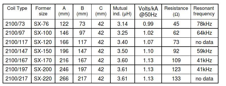
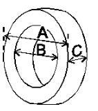
2 Rogowski Coil Unshielded RC: ROCOIL SX-170 M: µh 2
 Core 2 (Inner) : 154 x 134 x 54.5 mm / 0.1 mm band thickness (µ at 4mA/cm ~ 100000) Core 3-4 (Top and Bottom) : 260 x 134 x 5 mm / 0.")
3 Configuration of Magnetic Shield Magnetic shield was constructed by Mumetal cores and flat rings. Dimensions Core 1 (Outer) : 260 x 240 x 54.5 mm / 0.1 mm band thickness (µ at 4mA/cm ~ 60000) Core 2 (Inner) : 154 x 134 x 54.5 mm / 0.1 mm band thickness (µ at 4mA/cm ~ ) Core 3-4 (Top and Bottom) : 260 x 134 x 5 mm / 0.1 mm band thickness (µ at 4mA/cm ~ ) 3


4 Assembly of Magnetic Shield Inner Protection Box Inner Winding 400 Turns with 0,9 mm enameled copper wire Insulation of Top and Bottom Parts Applying of Magnetic Shield 4


5 Assembly of Magnetic Shield Flat Rings Outer Winding Protection box with PSP material Final Isolation 5
6 Calibration Method Current Supply Max. 6000A Measuring Bridge for Electronic Current Transformer WM3000I Reference Current Transformer Rocoil SX-170 M=3.604 µh 500A / 5A applying appropriate primary currents to the RC and the reference CT measuring the ratio error and phase displacement of the RC with the Bridge 6


7 Calibration Setup Measuring Bridge WM3000I AC Power Source Magnetic Shielded Rogowoski Coil Capacitive Bank Reference Current Transformer Unshielded Rogowoski Coil 7
8 Current Linearity Before Magnetic Shield After Magnetic Shield Primary Pos No: Current Ratio Error Phase Error A % crad ,024-0, ,025-0, ,025-0, ,025-0, ,025-0, ,024-0, ,025-0, ,024-0,004 Primary Pos No: Current Ratio Error Phase Error A % crad ,015-0, ,015-0, ,016-0, ,016-0, ,018-0, ,019-0, ,019-0, ,018-0,001 The reason of difference between ratio errors might be regarding to the tightening of Rogowski Coil. Manufacturer declares that gap error of 0.3mm would introduce an output error of less than 0.1%. 8
9 Position of Current Conductor Before Magnetic Shield Primary Current 400A Frequency : 50 Hz Ratio Error (%) Phase Error (crad) Ratio Error (%) Phase Error (crad) Ratio Error (%) Phase Error (crad) Ratio Error (%) Phase Error (crad) Pos No: d = 85 mm d = 105 mm d = 85 mm d = 105 mm 0 0,025-0,004 Deviations from Pos. 0 Deviations from Pos ,008-0,004-0,027-0,004-0,033 0,000-0,052 0, ,008-0,004-0,063-0,004-0,033 0,000-0,088 0, ,071-0,004 0,105-0,004 0,046 0,000 0,080 0, ,003-0,004-0,037-0,004-0,028 0,000-0,062 0,000 After Magnetic Shield Primary Current 400A Frequency : 50 Hz Ratio Error (%) Phase Error (crad) Ratio Error (%) Phase Error (crad) 1 Pos No: d = 105 mm d = 105 mm 0 0,018-0,001 Deviations from Pos ,018-0,001 0,000 0, ,018-0,001 0,000 0, ,018-0,001 0,000 0, ,019-0,001 0,001 0,000 d 4 0 Difference between the worst case (Conductor touching the outer winding) and reference (conductor in the center of the coil) was less than 10 ppm * The diameter of conductor is 20 mm 9
10 Position of Nearby Current Conductor 0 d Before Magnetic Shield After Magnetic Shield Primary Current 400A Frequency : 50 Hz Ratio Error d (cm) (%) Phase Error (crad) 80 0,022-0,004 Ratio Error Phase Error (%) (crad) Deviations from d=80 cm 60 0,022-0,004 0,000 0, ,017-0,004-0,005 0, ,000-0,004-0,022 0,000 Primary Current 400A Frequency : 50 Hz Ratio Error d (cm) (%) Phase Error (crad) 80 0,018-0,001 Ratio Error Phase Error (%) (crad) Deviations from d=80 cm 60 0,018-0,001 0,000 0, ,018-0,001 0,000 0, ,019-0,001 0,001 0,000 The coupling is less than 10 ppm. 10
11 High Frequency Test Results Shielded Unshielded Freq Angular Freq Primary Current DMM 1 DMM 1 Ratio Measured Values Deviation µh µh Hz A V V % crad % crad 3,604 3, , , , ,067 2,090-0,001 3,604 3, , , , ,067 2,091-0,004 0,001-0,003 3,604 3, , , , ,067 2,091-0,009 0,001-0,008 3,604 3, , , , ,067 2,091-0,014 0,001-0,013 3,604 3, , , , ,067 2,092-0,019 0,002-0,018 3,604 3, , , , ,067 2,093-0,024 0,003-0,023 3,604 3, , , , ,067 2,095-0,029 0,005-0,028 3,604 3, , , , ,067 2,097-0,033 0,007-0,032 3,604 3, , , , ,067 2,100-0,038 0,010-0,037 3,604 3, , , , ,067 2,103-0,042 0,013-0,041 3,604 3, , , , ,067 2,107-0,047 0,017-0,046 NI PXIe-1071 Digitizer Based Bridge was used. No integrator was used. Method: Appropriate currents are applied both the magnetic shielded RC and similar RC without shielded, the secondaries of them are compared with the Digitizer Based Bridge. 11
12 Frequency Response Test Results Frequency Response Error RE variation PE variation Frequency 12
13 (VTT MIKES) Current Linearity Linearity of Rogowski coil Measured againts VTT MIKES Rogowski coil dm/m [x10-6 ] Increasing current Decreasing current Applied Current Hz 13
14 (VTT MIKES) Temperature Compensation % Rogowski coil 40 Before temperature compensation % % ppm/K % % % R>10Gohm Temperature % % % 0 0:00 0:30 1:00 1:30 2:00 2:30 3:00 3:30 4:00 4:30 5:00 5:30 6:00 6:30 7:00 7:30 8:00 8: % Rogowski coil with R=9500 ohm 45 After temperature compensation % resistor % 35 in parallel with the coil % 30 R=9.5k Temperature 3 ppm/k % C to 36 C % % 0:00 0:30 1:00 1:30 2:00 2:30 3:00 3:30 4:00 4:30 5:00 5:30 6:00 6:30 7:00 7:30 8:
15 Summary Manufacturer Declares Influence of Conductor Position: If the conductor is moved from the central position by a distance equal to 0.5 x the inner coil radius the output will change by less than 0.1%. Influence of External Magnetic Fields: the pick-up for any orientation of the coil is less than 0.1% compared with the output of the coil Our Objective to reduce the immunity of a Rogowski coil against coupling magnetic fields by more than factor of
16 Summary Effect of current conductor position Effect of nearby current conductor Current linearity Temperature dependence < 10 ppm < 10 ppm < 5 ppm < 25 ppm Variations under these effects were decreased by approximately 100 times. Maximum primary current : 1000A, M=3,604 µh OD : 265 mm, ID : 125 mm, H : 75 mm, Weight: 12 kg Shielded RC is much heavier, More expensive than the conventional RC 16


17 Thanks for your attention
A COMPLEX CURRENT RATIO DEVICE FOR THE CALIBRATION OF CURRENT TRANSFORMER TEST SETS
 Metrol. Meas. Syst., Vol. XVIII (2011), No. 1, pp. 159-164 METROLOGY AND MEASUREMENT SYSTEMS Index 330930, ISSN 0860-8229 www.metrology.pg.gda.pl A COMPLEX CURRENT RATIO DEVICE FOR THE CALIBRATION OF CURRENT
Alternative Coupling Method for Immunity Testing of Power Grid Protection Equipment
 Alternative Coupling Method for Immunity Testing of Power Grid Protection Equipment Christian Suttner*, Stefan Tenbohlen Institute of Power Transmission and High Voltage Technology (IEH), University of
CURRENT TRANSFORMERS FOR ELECTRONIC WATTHOUR METERS ADVANCED MATERIALS THE KEY TO PROGRESS
 CURRENT TRANSFORMERS FOR ELECTRONIC WATTHOUR METERS ADVANCED MATERIALS THE KEY TO PROGRESS CURRENT TRANSFORMERS FOR ELECTRONIC WATTHOUR METERS VACUUMSCHMELZE GmbH & Co. KG (VAC) is one of the worldwide
RCTrms Technical Notes
 RCTrms Technical Notes All measuring instruments are subject to limitations. The purpose of these technical notes is to explain some of those limitations and to help the engineer maximise the many advantages
LFR: flexible, clip-around current probe for use in power measurements
 LFR: flexible, clip-around current probe for use in power measurements These technical notes should be read in conjunction with the LFR short-form datasheet. Power Electronic Measurements Ltd Nottingham
Tutorial: designing a converging-beam electron gun and focusing solenoid with Trak and PerMag
 Tutorial: designing a converging-beam electron gun and focusing solenoid with Trak and PerMag Stanley Humphries, Copyright 2012 Field Precision PO Box 13595, Albuquerque, NM 87192 U.S.A. Telephone: +1-505-220-3975
Review 6. unlike poles cause the magnets to attract. like poles cause the magnets to repel.
 Review 6 1. The two characteristics of all magnets are: they attract and hold Iron, and, if free to move, they will assume roughly a south - north position. 2. Lines of flux always leave the north pole
CHAPTER IV DESIGN OF TESLA COIL
 CHAPTER IV DESIGN OF TESLA COIL In this chapter, the design and calculation regarding spark gap tesla coil is shown as well as the design for the voltage regulator and the zero voltage switching driver
Units. In the following formulae all lengths are expressed in centimeters. The inductance calculated will be in micro-henries = 10-6 henry.
 INDUCTANCE Units. In the following formulae all lengths are expressed in centimeters. The inductance calculated will be in micro-henries = 10-6 henry. Long straight round wire. If l is the length; d, the
Topic 4 Practical Magnetic Design: Inductors and Coupled Inductors
 Topic 4 Practical Magnetic Design: Inductors and Coupled Inductors Louis Diana Agenda Theory of operation and design equations Design flow diagram discussion Inductance calculations Ampere s law for magnetizing
World-Class Accuracy & Measurement Range (40 Conventional Models)
") AC/DC CURRENT SENSOR CT6904 Ultra-High Performance AC/DC Current Sensor World-Class Accuracy & Measurement Range (40 Conventional Models) 500 A (rms) Rated for measurement of large currents 4 MHz (±3 db)
AC/DC CURRENT SENSOR CT6904 Ultra-High Performance AC/DC Current Sensor World-Class Accuracy & Measurement Range (40 Conventional Models) 500 A (rms) Rated for measurement of large currents 4 MHz (±3 db)
ULTRASTAB IHF Precision Current Transducer
 ULTRASTAB 867-200IHF Precision Current Transducer The Ultrastab 867-200IHF Current Transducer is a model in the Ultrastab Current Transducer program. It is the second generation of current transducers
AC/DC Resistance Standard DRR-112
 AC/DC Resistance Standard DRR-112 Operator's Manual DTM Instruments, LLC www.dtminstruments.com Version 2.0 November 2013 Introduction The AC/DC resistance standard DRR-112 is used to calibrate resistance
EEE 202 ELECTRO-TECHNIC LAB. PART 7 THEORY
 EEE 0 ELECTRO-TECHNIC LAB. PART 7 THEORY Yrd. Doç. Dr. Serhan Yarkan Arş. Gör. Dilara Albayrak İSTANBUL COMMERCE UNIVERSITY Contents EXAMINATION OF LC FILTERS... 0.1 INTRODUCTION... EXAMINATION OF TRANSFORMER...
Feed back element in high performance gradient amplifiers Feed back element in precision current regulated power supplies
 ULTRASTAB 866 Precision Current Transducer The Ultrastab 866 Current Transducer is the most proven fluxgate transducer with onboar electronics in the Danfysik Current Transducer program. It is the first
A New Method for the Calibration of the mv Ranges of an AC Measurement Standard
 A New Method for the Calibration of the mv Ranges of an AC Measurement Standard Speaker/Author Neil Faulkner Fluke Corporation PO Box 9090, Everett, WA 98206 Phone: (425) 446-5538 FAX: (425) 446-5649 E-mail:
Current Probes. User Manual
 Current Probes User Manual ETS-Lindgren Inc. reserves the right to make changes to any product described herein in order to improve function, design, or for any other reason. Nothing contained herein shall
Generation of Sub-nanosecond Pulses
 Chapter - 6 Generation of Sub-nanosecond Pulses 6.1 Introduction principle of peaking circuit In certain applications like high power microwaves (HPM), pulsed laser drivers, etc., very fast rise times
For the electronic measurement of current: DC, AC, pulsed..., with galvanic separation between the primary and the secondary circuit.
 Current Transducer IN 1000-S N = 1000 A For the electronic measurement of current: DC, AC, pulsed..., with galvanic separation between the primary and the secondary circuit. Features Closed loop (compensated)
HTC Technical Manual
 10.04.009 Table of contents 1. General...3. Technical details...3.1. Primary winding...3.. Secondary winding...3.3. Top terminal...3.4. Rotary spark gap...3.5. Safety spark gap...4 3. Measurements...5
Chapter Moving Charges and Magnetism
 100 Chapter Moving Charges and Magnetism 1. The power factor of an AC circuit having resistance (R) and inductance (L) connected in series and an angular velocity ω is [2013] 2. [2002] zero RvB vbl/r vbl
VE7CNF - 630m Antenna Matching Measurements Using an Oscilloscope
 VE7CNF - 630m Antenna Matching Measurements Using an Oscilloscope Toby Haynes October, 2016 1 Contents VE7CNF - 630m Antenna Matching Measurements Using an Oscilloscope... 1 Introduction... 1 References...
Walchand Institute of Technology. Basic Electrical and Electronics Engineering. Transformer
 Walchand Institute of Technology Basic Electrical and Electronics Engineering Transformer 1. What is transformer? explain working principle of transformer. Electrical power transformer is a static device
High Voltage Engineering
 High Voltage Engineering Course Code: EE 2316 Prof. Dr. Magdi M. El-Saadawi www.saadawi1.net E-mail : saadawi1@gmail.com www.facebook.com/magdi.saadawi 1 Contents Chapter 1 Introduction to High Voltage
AC Flexible Current Sensor CT /-02/-03, CT7044/CT7045/CT7046
 1 AC Flexible Current Sensor CT9667-01/-02/-03, CT7044/CT7045/CT7046 Hideo Matsubayashi Engineering Division 5, Engineering Department 2 Abstract The AC Flexible Current Sensor CT9667-00 series (which
Inductive sensors. The operating principle is based on the following relationship: L=f(x) M=g(x)
 M=g(x)") Inductive sensors The operating principle is based on the following relationship: L=f(x) M=g(x) High robusteness against influencing quantities (environmental) 1 L variation based Inductive Sensors Basics
Inductive sensors The operating principle is based on the following relationship: L=f(x) M=g(x) High robusteness against influencing quantities (environmental) 1 L variation based Inductive Sensors Basics
total j = BA, [1] = j [2] total
![total j = BA, [1] = j [2] total](/thumbs/85/91692343.jpg "total j = BA, [1] = j [2] total") Name: S.N.: Experiment 2 INDUCTANCE AND LR CIRCUITS SECTION: PARTNER: DATE: Objectives Estimate the inductance of the solenoid used for this experiment from the formula for a very long, thin, tightly wound
Name: S.N.: Experiment 2 INDUCTANCE AND LR CIRCUITS SECTION: PARTNER: DATE: Objectives Estimate the inductance of the solenoid used for this experiment from the formula for a very long, thin, tightly wound
Inductive sensors. The operating principle is based on the following relationship: L=f(x) M=g(x)
 M=g(x)") Inductive sensors The operating principle is based on the following relationship: L=f(x) M=g(x) High robusteness against influencing quantities (environmental) 1 L variation based Inductive Sensors Basics
Inductive sensors The operating principle is based on the following relationship: L=f(x) M=g(x) High robusteness against influencing quantities (environmental) 1 L variation based Inductive Sensors Basics
Exercises of resistors 1. Calculate the resistance of a 10 m long Copper wire with diameter d = 1.0 mm.
 Exercises of resistors 1. Calculate the resistance of a 10 m long Copper wire with diameter d = 1.0 mm. 2. Calculate the resistances of following equipment: using 220V AC a) a 1000 W electric heater b)
ULTRASTAB I U Precision
 ULTRASTAB 867-700I 867-700U Precision Current Transducer The Ultrastab 867-700I and 867-700U Current Transducers, are the latest models of the Ultrastab Current Transducers. They are the third generation
MAGNETOSCOP Measurement of magnetic field strengths in the range 0.1 nanotesla to 1 millitesla
 MAGNETOSCOP Measurement of magnetic field strengths in the range 0.1 nanotesla to 1 millitesla Extremely high sensitivity of 0.1 nanotesla with field and gradient probe Measurement of material permeabilities
Design and Construction of a150kv/300a/1µs Blumlein Pulser
 Design and Construction of a150kv/300a/1µs Blumlein Pulser J.O. ROSSI, M. UEDA and J.J. BARROSO Associated Plasma Laboratory National Institute for Space Research Av. dos Astronautas 1758, São José dos
ELECTRICAL MEASUREMENTS
 R10 Set No: 1 1. a) Derive the expression for torque equation for a moving iron attraction type instrument and comment up on the nature of scale [8] b) Define the terms current sensitivity, voltage sensitivity
Magnetics Design. Specification, Performance and Economics
 Magnetics Design Specification, Performance and Economics W H I T E P A P E R MAGNETICS DESIGN SPECIFICATION, PERFORMANCE AND ECONOMICS By Paul Castillo Applications Engineer Datatronics Introduction The
Travelling Wave Based DC Line Fault Location in VSC HVDC Systems
 M.Sc. Thesis Presentation Travelling Wave Based DC Line Fault Location in VSC HVDC Systems K.P.A.N. Pathirana Department of ECE University of Manitoba Canada. Outline Introduction Surge detection method
Radio Frequency Electronics
 Radio Frequency Electronics Preliminaries II Guglielmo Giovanni Maria Marconi Thought off by many people as the inventor of radio Pioneer in long-distance radio communications Shared Nobel Prize in 1909
Looking for magnetic parts? Low Permeability Nanocrystalline Cores Nanophy. Material on design Permeability on demand
 Looking for magnetic parts? kµ cores Low Permeability Nanocrystalline Cores Nanophy Stainless & Nickel Alloys Components Material on design Permeability on demand Permeability range from 2 to 3 Material
ELECTROMAGNETIC INDUCTION AND ALTERNATING CURRENT (Assignment)
") ELECTROMAGNETIC INDUCTION AND ALTERNATING CURRENT (Assignment) 1. In an A.C. circuit A ; the current leads the voltage by 30 0 and in circuit B, the current lags behind the voltage by 30 0. What is the
ELECTROMAGNETIC INDUCTION AND ALTERNATING CURRENT (Assignment) 1. In an A.C. circuit A ; the current leads the voltage by 30 0 and in circuit B, the current lags behind the voltage by 30 0. What is the
PRECISION CLAMP ON FLEXIBLE ROGOWSKI COIL CURRENT TRANSFORMER
 JRF333M-X 333mVAC 24VDC, 2VA S1 S2 Vin + Vin - PRECISION CLAMP ON FLEXIBLE ROGOWSKI COIL CURRENT TRANSFORMER LED SINGLE PHASE output 333mV AC THREE PHASE output 333mV AC Power isast OPEN RCT is made with
AP Physics C. Alternating Current. Chapter Problems. Sources of Alternating EMF
 AP Physics C Alternating Current Chapter Problems Sources of Alternating EMF 1. A 10 cm diameter loop of wire is oriented perpendicular to a 2.5 T magnetic field. What is the magnetic flux through the
IJSRD - International Journal for Scientific Research & Development Vol. 2, Issue 04, 2014 ISSN (online):
:") IJSRD - International Journal for Scientific Research & Development Vol. 2, Issue 04, 2014 ISSN (online): 2321-0613 Conditioning Monitoring of Transformer Using Sweep Frequency Response for Winding Deformation
IJSRD - International Journal for Scientific Research & Development Vol. 2, Issue 04, 2014 ISSN (online): 2321-0613 Conditioning Monitoring of Transformer Using Sweep Frequency Response for Winding Deformation
Experiment 5: Grounding and Shielding
 Experiment 5: Grounding and Shielding Power System Hot (Red) Neutral (White) Hot (Black) 115V 115V 230V Ground (Green) Service Entrance Load Enclosure Figure 1 Typical residential or commercial AC power
High Performance Current Transducer IT 200-S ULTRASTAB = A. ε L
 High Performance Current Transducer IT 200-S ULTRASTAB For the electronic measurement of currents: DC, AC, pulsed..., with galvanic isolation between the primary circuit and the secondary circuit. I PM
Field Instrument Cable. Electrical Noise
 Field Instrument Cable Electrical Noise 1 Electrical Noise Instrument Cables are Susceptible to 4 Types of Noise: Static Magnetic Cross-Talk Common Mode 2 Static Noise Static Noise is caused by an electric
C240-NFSM-3M. Jumper Assembly Sample Label. Product Classification. General Specifications. Return Loss/VSWR
 C240-NFSM-3M Product Classification Brand Product Series Product Type CNT Jumper with interface types N Female and SMA Male, 3m CNT Braided cable assembly General Specifications Body Style, Connector A
NOVEL PROTECTION SYSTEMS FOR ARC FURNACE TRANSFORMERS
 NOVEL PROTECTION SYSTEMS FOR ARC FURNACE TRANSFORMERS Ljubomir KOJOVIC Cooper Power Systems - U.S.A. Lkojovic@cooperpower.com INTRODUCTION In steel facilities that use Electric Arc Furnaces (EAFs) to manufacture
Single-turn and multi-turn coil domains in 3D COMSOL. All rights reserved.
 Single-turn and multi-turn coil domains in 3D 2012 COMSOL. All rights reserved. Introduction This tutorial shows how to use the Single-Turn Coil Domain and Multi-Turn Coil Domain features in COMSOL s Magnetic
Jacques Audet VE2AZX. Nov VE2AZX 1
 Jacques Audet VE2AZX VE2AZX@amsat.org Nov. 2006 VE2AZX 1 - REASONS FOR USING A BALUN - TYPES OF BALUNS - CHECK YOUR BALUN WITH AN SWR ANALYZER - MEASURING THE IMPEDANCE OF A NUMBER OF FERRITES - IMPEDANCE
Vibrating Wire Instrumentation
 Vibrating Wire Instrumentation Design, Operations & Lines Test Results System Diagram - Fig 1 Sensor Excitation Circuit Differential Amplifier + + Sensor Coil - - High Pass 100 Hz Digital Filter Low Pass
CDAX 605 High Precision Capacitance & Dissipation Factor Test Set
 CDAX 605 High Precision Capacitance & Dissipation Factor Test Set 1 Tan delta and capacitance measurements Hi V A Lo Ground C HL Measure with AC test signal, use Ohms law to calculate: Dissipation factor
Group F : Sl. No. - 1) 33/0.403 KV, 100 KVA Station Transformer GUARANTEED & OTHER TECHNICAL PARTICULARS. Table : A
 33/0.403 KV, 100 KVA Station Transformer GUARANTEED & OTHER TECHNICAL PARTICULARS. Table : A") Group F : No. - 1) 33/0.403 KV, 100 KVA Station Transformer GUARANTEED & OTHER TECHNICAL PARTICULARS Table : A No. Description 1. Make & Manufacturer 2. Place of Manufacturer 3. Voltage Ratio 4. Rating
Group F : No. - 1) 33/0.403 KV, 100 KVA Station Transformer GUARANTEED & OTHER TECHNICAL PARTICULARS Table : A No. Description 1. Make & Manufacturer 2. Place of Manufacturer 3. Voltage Ratio 4. Rating
North D25-06S. High performance silk dome tweeter for cabinets six to ten inches in width
 North D25-06S High performance silk dome tweeter for cabinets six to ten inches in width FEATURES: 25 mm Hand-Coated Silk Dome Underhung Geometry 1.0mm p-p excursion MAPD-loaded rear chambers Reinforced
Telemetrie-Messtechnik Schnorrenberg
 Telemetrie-Messtechnik Schnorrenberg MTP-IND-PWR User Manual Inductive power supply set Power supply for power head 25 and 50mm mounting tape to fix coil on shaft Ferrite tape 30mmx3m CUL 1.00 mm (Enamelled
Get Involved with Low Cost Rogowski Coil Current Sensor Development. RevA
 Get Involved with Low Cost Rogowski Coil Current Sensor Development. RevA Contents 1 The Project... 1 2 The Patent... 3 3 The Offer... 5 4 The Appendix... 5 4.1 What is a Rogowski Coil... 5 4.2 InnovateUK
Ferronato Helmholtz Coils
 INNOVATION IN MAGNETICS DS4292/2 Ferronato Helmholtz Coils www.bartington.com Ferronato Helmholtz Coils Ferronato Helmholtz Coil Systems These Ferronato Helmholtz coils are used in the calibration of magnetic
Inductive adder prototype pulse generator for FCC-hh kickers
 Inductive adder prototype pulse generator for FCC-hh kickers D. Woog Acknowledgements: M.J. Barnes, J. Holma, T. Kramer 14/04/2018 David Woog FCC WEEK 2018 1 Content Inductive adder introduction Requirements
COIL WINDING ISSUES P. Fabbricatore INFN Genova LCD - Magnet 13Oct09. Coil winding issues
 Coil winding issues Based on experience acquired with CMS coil construction, some preliminary considerations about the envisaged winding (and in general manufacturing) issues of a large superconducting
High Precision Current Measurement for Power Converters
 High Precision Current Measurement for Power Converters M. Cerqueira Bastos CERN, Geneva, Switzerland Abstract The accurate measurement of power converter currents is essential to controlling and delivering
Design and Fabrication of Tesla Coil
 Design and Fabrication of Tesla Coil Prof. S. M. Shaikh 1, Mr. Harshad Dube 2, Mrs. Sushmita Walunj 3, Mrs. Namita Thorat 4, 1 Assistant Professor, Electrical Engineering, AISSMS s IOIT, Maharashtra, India
APPLICATION NOTE AN02
 FT50-000 FWD-xA-B FWD KIT # APPLICATION NOTE AN0 00 W Forward Converter By: James Lau TAKE THE PAIN OUT OF FORWARD CONVERTER DESIGN If you have ever designed a 50 Watt converter, you would probably agree
Experiment 4: Grounding and Shielding
 4-1 Experiment 4: Grounding and Shielding Power System Hot (ed) Neutral (White) Hot (Black) 115V 115V 230V Ground (Green) Service Entrance Load Enclosure Figure 1 Typical residential or commercial AC power
PRELIMINARIES. Generators and loads are connected together through transmission lines transporting electric power from one place to another.
 TRANSMISSION LINES PRELIMINARIES Generators and loads are connected together through transmission lines transporting electric power from one place to another. Transmission line must, therefore, take power
Enhanced Quality with a Touch of Style
 Rudolf Current Transformer Enhanced Quality with a Touch of Style Current Transformer Enhanced Quality with a Touch of Style New Products Rudolf launched our new encapsulated current transformer. Portraying
TEMPERATURE AND FREQUENCY DEPENDENCE OF PRECISION CURRENT TRANSFORMER BASED ON ROGOWSKI COILS
 XIX IMEKO World Congress Fundamental and Applied Metrology eptember 6, 009, Lisbon, Portugal EMPEAE AND FEQENCY DEPENDENCE OF PECIION CEN ANFOME BAED ON OGOWKI COIL Luka Ferković, Damir Ilić, Kristina
Investigation of skin effect on coaxial cables
 Investigation of skin effect on coaxial cables Coaxial cables describe a type of cables that has an inner conductor surrounded by an insulator, which is surrounded by another layer of conductor and insulator
Temperature measurements with resistance thermometer General information
 Temperature measurements with resistance thermometer General information Temperature measurements with resistance thermometer The measuring principle of temperature measurement with resistance thermometers
Application of Digital Sampling Method for Voltage Transformer Test Set Calibrations. Hüseyin Çaycı
 Application of Digital Sampling Method for Voltage Transformer Test Set Calibrations Hüseyin Çaycı National Metrology Institute of Turkey, TUBITAK UME, P.O.Box:54, 41470, Gebze, Kocaeli, Turkey, phone:
Electrical Theory 2 Lessons for Fall Semester:
 Electrical Theory 2 Lessons for Fall Semester: Lesson 1 Magnetism Lesson 2 Introduction to AC Theory Lesson 3 Lesson 4 Capacitance and Capacitive Reactance Lesson 5 Impedance and AC Circuits Lesson 6 AC
AVA5-50FX. Product Classification. Standards And Qualifications. Construction Materials. Dimensions. Electrical Specifications
 AVA5RK-50FX, HELIAX Andrew Virtual Air Coaxial Cable, corrugated copper, 7/8 in, black, Non-halogenated, fire retardant polyolefin jacket B2ca-s1b,d1 Product Classification Brand Product Series Product
Transmission Lines and TDR
 Transmission Lines and TDR Overview This is the procedure for lab 2a. This is a one-week lab. The prelab should be done BEFORE going to the lab session. In this lab, the characteristics of different transmission
High Performance Current Transducer ITL 900-T = A
 High Performance Current Transducer ITL 900-T For the electronic measurement of currents: DC, AC, pulsed..., with galvanic separation between the primary and the secondary circuit. I PM = 0... 900 A Electrical
For ultra-high precision measurement of current: DC, AC, pulsed..., with galvanic separation between primary and secondary. Applications.
 Current Transducer IT 700-S ULTRASTAB I PM = 700 A For ultra-high precision measurement of current: DC, AC, pulsed..., with galvanic separation between primary and secondary. Features Closed loop (compensated)
What causes the Out-of-Balance Current in the coax and why does it Radiate?
 The EH Antenna - Out of Balance Current or Longitudinal Mode Current in the Coaxial Cable causes radiation from the coax. But how large a proportion of the total power is radiated or lost from this Current?
RF300 LARGE LOOP ANTENNA
 LAPLACE INSTRUMENTS LTD RF300 LARGE LOOP ANTENNA USER GUIDE Serial Number 9072 Issue 5 May 2010 Page 1 INDEX Introduction 3 Packing list 3 Assembly 5 Calibration loop 12 Calibration 13 Operation 14 In
DETECTION OF SUB LAYER FATIGUE CRACKS UNDER AIRFRAME RIVETS
 DETECTION OF SUB LAYER FATIGUE CRACKS UNDER AIRFRAME RIVETS Buzz Wincheski and Min Namkung NASA Langley Research Center Hampton, VA 23681 INTRODUCTION The Rotating Self-Nulling Probe System developed as
Over-voltage Trigger Device for Marx Generators
 Journal of the Korean Physical Society, Vol. 59, No. 6, December 2011, pp. 3602 3607 Over-voltage Trigger Device for Marx Generators M. Sack, R. Stängle and G. Müller Karlsruhe Institute of Technology
SoftRock v6.0 Builder s Notes. May 22, 2006
 SoftRock v6.0 Builder s Notes May 22, 2006 Be sure to use a grounded tip soldering iron in building the v6.0 SoftRock circuit board. The soldering iron needs to have a small tip, (0.05-0.1 inch diameter),
R-X SERIES. Decade Resistor
 PRECISION INSTRUMENTS FOR TEST AND MEASUREMENT R-X SERIES Decade Resistor User and Service Manual Effectivity: Serial Numbers beginning with P2 RX im/august, 2002 Copyright 2002 IET Labs, Inc. IET LABS,
For the electronic measurement of current: DC, AC, pulsed..., with galvanic separation between the primary and the secondary circuit.
 Current Transducer IN 1000-S I P N = 1000 A For the electronic measurement of current: DC, AC, pulsed..., with galvanic separation between the primary and the secondary circuit. Features Closed loop (compensated)
Inductive sensors. The operating principle is based on the following relationship: L=f(x) M=g(x)
 M=g(x)") Inductive sensors The operating principle is based on the following relationship: L=f(x) M=g(x) High robusteness against influencing quantities (environmental) 1 L variation based Inductive Sensors Basics
Inductive sensors The operating principle is based on the following relationship: L=f(x) M=g(x) High robusteness against influencing quantities (environmental) 1 L variation based Inductive Sensors Basics
Improved High-Frequency Planar Transformer for Line Level Control (LLC) Resonant Converters
 Resonant Converters") Improved High-Frequency Planar Transformer for Line Level Control (LLC) Resonant Converters Author Water, Wayne, Lu, Junwei Published 2013 Journal Title IEEE Magnetics Letters DOI https://doi.org/10.1109/lmag.2013.2284767
Improved High-Frequency Planar Transformer for Line Level Control (LLC) Resonant Converters Author Water, Wayne, Lu, Junwei Published 2013 Journal Title IEEE Magnetics Letters DOI https://doi.org/10.1109/lmag.2013.2284767
Transducer transmitter BILT 4 II 2(1) G. Technical Manual
 G. Technical Manual") GB Transducer transmitter BILT 4 II 2(1) G Technical Manual Transducer transmitter BILT 4 Contents Introduction General... 3 Ex.safety description... 4 Technical data... 5 Installation General... 6 Mechanical
GB Transducer transmitter BILT 4 II 2(1) G Technical Manual Transducer transmitter BILT 4 Contents Introduction General... 3 Ex.safety description... 4 Technical data... 5 Installation General... 6 Mechanical
C400-UMUM-100. Jumper Assembly Sample Label. Product Classification. General Specifications. Return Loss/VSWR
 C400-UMUM-100 Product Classification Brand Product Series Product Type CNT Jumper with interface types UHF Male and UHF Male, 30.48 m CNT Braided cable assembly General Specifications Body Style, Connector
How to Select the Right Current Probe APPLICATION NOTE
 How to Select the Right Current Probe APPLICATION NOTE Overview Oscilloscope current probes enable oscilloscopes to measure current, extending their use beyond just measuring voltage. Basically, current
Table of Contents. Table of Figures. Table of Tables
 Abstract The aim of this report is to investigate and test a transformer and check if it is good to use by doing the following tests continuity test, insulation test, polarity test, open circuit test,
RFID. Technical Training. Low Frequency Antenna Design. J.A.G Jan 2009 Texas Instruments Proprietary Information 1
 Technical Training Low Frequency Antenna Design J.A.G Jan 2009 Texas Instruments Proprietary Information 1 Custom Antenna Design There are many reasons why integrators may wish to make their own Low Frequency
Flexible PCB-Based Eddy Current Array Probes for the Inspection of Turbine Components
 Flexible PCB-Based Eddy Current Array Probes for the Inspection of Turbine Components Andre Lamarre - OlympusNDT-Quebec City Canada Benoit Lepage - OlympusNDT-Quebec City-Canada Tommy Bourgelas - OlympusNDT-Quebec
Non-Contact Capacitance Gauging Instrument & Series 2800 Capacitive Probes
 4810 Non-Contact Capacitance Gauging Instrument & Series 2800 Capacitive Probes Sub nanometer resolution for ultra-precise measurements Exceptional temperature stability Wide variety of precision capacitive
Aligarh College of Engineering & Technology (College Code: 109) Affiliated to UPTU, Approved by AICTE Electrical Engg.
 Affiliated to UPTU, Approved by AICTE Electrical Engg.") Aligarh College of Engineering & Technology (College Code: 19) Electrical Engg. (EE-11/21) Unit-I DC Network Theory 1. Distinguish the following terms: (a) Active and passive elements (b) Linearity and
Aligarh College of Engineering & Technology (College Code: 19) Electrical Engg. (EE-11/21) Unit-I DC Network Theory 1. Distinguish the following terms: (a) Active and passive elements (b) Linearity and
Some hints/tips on how to assemble nice COAX TRAPS!
 Some hints/tips on how to assemble nice COAX TRAPS! Before we start to assemble our traps, here some general info as introduction : Coax traps are cheap, easy to assemble in a reproducible manner, very
3.2 Measurement of high voltages
 DEPT OF HIGH VOLTAGE AND INSULATION ENG, HONGQING UNIVERSITY Part I- hapter 3: Insulation test techniques 3. Measurement of high voltages Instructor: Dr. Jian Li Lecture 7- DEPT OF HIGH VOLTAGE AND INSULATION
RING CORE CURRENT TRANSFORMERS FOR LOW VOLTAGE TYPE AOS USER MANUAL
 RING CORE CURRENT TRANSFORMERS FOR LOW VOLTAGE TYPE AOS F.T.M. S. r. l. Fabbrica trasformatori di misura Via Po, 3 20090 Opera MI - Italy Tel : +39 (0)2 576814 Fax : +39 (0)2 57605296 E-mail: info@ftmsrl.it
MTP-NT INSTRUCTIONS FOR QUALIFIED PERSONNEL ONLY!
 KMT - Kraus Messtechnik GmbH Gewerbering 9, D-83624 Otterfing, Germany, +49-8024-48737, Fax.-5532 Home Page http://www.kmt-telemetry.com, Email: info@kmt-telemetry.com MTP-NT Preliminary version (0XX)
Target Temperature Effect on Eddy-Current Displacement Sensing
 Target Temperature Effect on Eddy-Current Displacement Sensing Darko Vyroubal Karlovac University of Applied Sciences Karlovac, Croatia, darko.vyroubal@vuka.hr Igor Lacković Faculty of Electrical Engineering
1 Introduction. Webinar sponsored by: Cost-effective uses of close-field probing. Contents
 1of 8 Close-field probing series Webinar #1 of 2, Cost-effective uses of close-field probing in every project stage: emissions, immunity and much more Webinar sponsored by: Keith Armstrong CEng, EurIng,
TRANSFORMER TECHNOLOGY GPT
 Core-Form TRANSFORMER TECHNOLOGY GlobalPT Corporation performs research and engineering developments and co-ordination of works of technical partners in the field of technological progress and commercial
I P. /dt. di p V S+ Applications. Standards. 1) IEC ed1.0: 2007; IEC : ed1.0: 2012
 IEC ed1.0: 2007; IEC : ed1.0: 2012") Ref: ART-B22-D70, ART-B22-D125, ART-B22-D175 Flexible clip-around Rogowski coil for the electronic measurement of AC current with galvanic separation between the primary circuit (power) and the secondary
Ref: ART-B22-D70, ART-B22-D125, ART-B22-D175 Flexible clip-around Rogowski coil for the electronic measurement of AC current with galvanic separation between the primary circuit (power) and the secondary
Bill Ham Martin Ogbuokiri. This clause specifies the electrical performance requirements for shielded and unshielded cables.
 098-219r2 Prepared by: Ed Armstrong Zane Daggett Bill Ham Martin Ogbuokiri Date: 07-24-98 Revised: 09-29-98 Revised again: 10-14-98 Revised again: 12-2-98 Revised again: 01-18-99 1. REQUIREMENTS FOR SPI-3
Signal and Noise Measurement Techniques Using Magnetic Field Probes
 Signal and Noise Measurement Techniques Using Magnetic Field Probes Abstract: Magnetic loops have long been used by EMC personnel to sniff out sources of emissions in circuits and equipment. Additional
Understanding and Optimizing Electromagnetic Compatibility in Switchmode Power Supplies
 Understanding and Optimizing Electromagnetic Compatibility in Switchmode Power Supplies 1 Definitions EMI = Electro Magnetic Interference EMC = Electro Magnetic Compatibility (No EMI) Three Components