Solar Dynamics Observatory
|
|
|
- Moses Bradford
- 5 years ago
- Views:
Transcription
1 Solar Dynamics Observatory Solar Dynamics Observatory System Concept Review Helioseismic and Magnetic Imager Draft Presentation 21 March 2003 Hansen Experimental Physics Laboratory Stanford, CA Lockheed Martin Space Systems Company Solar & Astrophysics Laboratory Palo Alto, CA - Scherrer 1


 -2.")


2 Science Objectives B Solar Dynamo J Sunspot Dynamics C Global Circulation 60 Latitude I Magnetic Connectivity -1 v (km s ) Year A Interior Structure -1.4 D Irradiance Sources 2.0 B (kg) -2.0 Flux (kg) Ic to disk center 10Mm H Far-side Imaging E Coronal Magnetic Field NOAA 9393 Far-side G Magnetic Stresses F Solar Subsurface Weather - Scherrer 2
3 Top Down View of Science Requirements NAS/NRC and NASA Roadmap Living With a Star SDO Mission Investigation Science Objectives Science Data Products Observations Observables Instrument Data Instrument Concept Instrument Requirements - SDO interface SDO S/C Concept Ground System - Scherrer 3
4 Science Objectives Convection-zone dynamics and the solar dynamo Structure and dynamics of the tachocline Variations in differential rotation Evolution of meridional circulation Dynamics in the near surface shear layer Origin and evolution of sunspots, active regions and complexes of activity Formation and deep structure of magnetic complexes of activity Active region source and evolution Magnetic flux concentration in sunspots Sources and mechanisms of solar irradiance variations Sources and drivers of solar activity and disturbances Origin and dynamics of magnetic sheared structures and d-type sunspots Magnetic configuration and mechanisms of solar flares Emergence of magnetic flux and solar transient events Evolution of small-scale structures and magnetic carpet Links between the internal processes and dynamics of the corona and heliosphere Complexity and energetics of the solar corona Large-scale coronal field estimates Coronal magnetic structure and solar wind Precursors of solar disturbances for space-weather forecasts Far-side imaging and activity index Predicting emergence of active regions by helioseismic imaging Determination of magnetic cloud Bs events - Scherrer 4
5 Science Data Products Science Data Products High-level data products which are input to the science analyses. These are time series of maps of physical quantities in and on the Sun. Internal rotation Ω(r,Θ) (0<r<R) Internal sound speed, cs(r,θ) (0<r<R) Full-disk velocity, v(r,θ,φ) and sound speed, cs(r,θ,φ) maps (0-30Mm) Carrington synoptic v and cs maps (0-30Mm) High-resolution v and cs maps (0-30Mm) Deep-focus v and cs maps (0-200Mm) Far-side activity index Line-of-Sight Magnetic field maps Vector Magnetic Field maps Coronal magnetic Field extrapolations Coronal and Solar wind models Brightness Images Context Magnetograms - Scherrer 5

6 Science Observations Science Objectives Implies Science Data Products Implies Observations, e.g. HS-3 Requires Observables Table shows which Observations are needed for which Science Data Products which are needed for which Science Objectives Rows are Science Objectives Columns are Science Data Products Text in cells identifies Observation types - Scherrer 6
7 Observables Requirements - Scherrer 7
8 Observables Requirements - Scherrer 8
9 Observables Requirements - Scherrer 9
10 Source of Requirements Investigation Science Objectives Duration of mission Completeness of coverage Science Data Products Roll accuracy Time accuracy (months) Observations Duration of sequence Cadence Completeness (95% of data sequence) Noise Resolution Time accuracy (days) Observables Sensitivity Linearity Acceptable measurement noise Image stability Time rate (minutes) Completeness (99.9% of observable data in 90s) Orbit knowledge Instrument Data Accuracy Noise levels Completeness (99.99% of data in filtergram) Tuning & shutter repeatability Wavelength knowledge Image registration Image orientation jitter Instrument Concept Mass Power Telemetry Envelope Sub-system requirements CCD: Thermal environment ISS: pointing drift rate, jitter Legs: pointing drift range to SDO Interface Requirements Ground System Processing System Data Distribution - Scherrer 10
11 Key Requirements - Scherrer 11
12 Instrument Concept The instrument is an evolution of the successful Michelson Doppler Imager instrument which has been operating on the SOHO spacecraft for over seven years. The raw observables are filtergrams of the full solar disk taken with a narrow band (~ 0.1 A bandpass) tunable filter in multiple polarizations. The primary science observables are Dopplergrams, line-of-sight magnetograms, vector magnetograms and continuum images computed from a series of filtergrams. Some of the key instrument design drivers include maintaining uniform image quality and performance through detailed optical and thermal design and rigorous testing. The vector magnetic field measurements are best decoupled from the helioseismology measurements, and a two camera design results to maintain image cadence and separate the two primary data streams. - Scherrer 12
13 Optical Layout - Scherrer 13

14 Optics Package Layout - Scherrer 14
15 Design Improves on MDI The common design features based on MDI: Front window designed to be the initial filter with widest bandpass. Simple two element refracting telescope. Image Stabilization System with a solar limb sensor and PZT driven tip-tilt mirror. Narrow band tunable filter consisting of a multi-element Lyot filter and two Michelson interferometers. Similar hollow core motors, filterwheel mechanisms and shutters. The improvements from MDI: The observing line is the Fe I nm absorption line instead of the Ni I nm line. This observing line is used for both Doppler and magnetic measurements. Rotating waveplates are used for polarization selection instead of a set of polarizing optics in a filterwheel mechanism. An additional tunable filter element is included in order to provide the measurement dynamic range required by the SDO orbit. The CCD format will be 4096x4096 pixels instead of 1024x1024 pixels in order to meet the angular resolution requirements. Two CCD cameras are used in parallel in order to make both Doppler and vector magnetic field measurements at the required cadence. The is no image processor all observable computation is performed on the ground. - Scherrer 15
16 Subsystems Optics Package Structure The optic package structure subsystem includes the optics package structure, the mounts for the various optical components and the legs that mount the optics package to the spacecraft. Optics Subsystem Includes all the optical elements except the filters Filter subsystem The filter subsystem includes all the filters and Michelsons Provides the ability to select the wavelenght to image Thermal Subsystem Controls the temperature of the optics pkg., the filter oven, CCDs, and the front window. Implements the decontamination heating of the CCD. Image Stabilization Subsystem Consists of active mirror, limb sensor, precision digital & analog control electronics It actively stabilizes the image reducing the effects of jitter Mechanisms Subsystem The mechanisms subsystem includes shutters, hollow-core motors, calibration/focus wheels, alignment mechanism, and the aperture door CCD Camera Subsystem The CCD camera subsystem includes 4Kx4K CCDs and the camera electronics box(es) Electronics Subsystem Provides conditioned power and control for all subsystems as well as C&DH hardware Software Subsystem The software subsystem includes the C&DH interface to the spacecraft and controls all of the other subsystems - Scherrer 16
17 Functional Block Diagram CCD CCD CCD Driver Card (2) Clock & sequencer CDS/ADC Command / Data Interface IEEE 1355 PWB LVDS Camera Camera interface Interface (SMClite) ) Buffer Buffer memory Memory (2x4Kx4Kx16) x x x 16) Housekeeping Housekeeping ADC, ADC, & master & Master clock Clock DC DC -DC- DC power Power converter Converter PWB Mechanism Mechanism & & heater Heater controllers Controllers Control Camera data PWB Data Data compressor Compressor / & Buffer AEC Camera Electronics Box Image Stabilization System Limb Sensor & Active Mirror Mechanisms: Focus/Cal Wheels (2) Polarization Selectors (3) Tuning Motors (4) Shutters (2) Front Door Alignment Mechanism Filter Oven Control Structure Heaters Housekeeping Data Optics Package PWB ISS ISS (Limb (Limb tracker) tracker) Control PWB ISS ISS (PZT (PZT drivers) drivers) PWB Housekeeping data Data acquisition Acquisition Control Control ISS data PWB PC/local PC/local bus bridge/ Bus Bridge EEPROM PWB Central Central processor Processor/ EEPROM Electronics Box Buffer Spacecraft memory Interface PCI Bus PWB Power converters Converters SDO SDO Spacecraft Spacecraft - Scherrer 17
18 Optics Subsystem 1 arc-sec diffraction limited image at the sensor Requires 14 cm aperture Requires 4096x4096 pixel sensor Solar disk at the sensor 4.9 cm For sensor with 12 um pixels Focus adjustment system with ±3 (TBC) depth of focus range and 16 steps Provide calibration mode that images the pupil on the sensor Provide beam splitter to divide the telescope beam between the filter oven and the limb tracker Provide telecentric beam through the Lyot filter Provide beam splitter to feed the output of the filter subsystem to two sensors Minimize scattered light on the sensor - Scherrer 18
19 Filter subsystem Central wavelength 6173Å Fe I line Reject 99% of solar heat load from the OP interior Total bandwidth 76mÅ FWHM Tunable range 500 må Very high stability and repeatability required (to be quantified) The required bandwidth obtained by cascading filters as follows Front window 50Å Blocker 8Å Lyot filter (5 element 1:2:4:8:16) 306 må Wide Michelson 172 må Narrow Michelson 86 må Tuning range requires use of three co-tuned elements Narrowest Lyot element Wide Michelson Narrow Michelson - Scherrer 19


20 MDI Lyot Elements and Michelson Interferometers - Scherrer 20
21 Thermal Subsystem Optics package thermal control Operating temperature range 15 to 25 C Active control to ±0.5 C Control loop in software Filter oven Operating temperature range 35 ± 4 C Temperature accuracy 0.5 C Temperature stability 0.01 C /hour Changes in internal temperature gradients as small as possible Dedicated analog control loop in controlled thermal environment Sensor (CCD detector) thermal control Operating 100 C to 30 C Stability over an orbit xx C? Decontamination mode raise CCD to 20 to 40 C (may need to be wider because of unregulated power) Front window thermal control Minimize radial gradients Return to normal operating temperature within 60 minutes of eclipse exit - Scherrer 21
22 Image Stabilization Subsystem Stability (over TBC second period) 0.1 arc-sec Range ± 14 arc-sec Frequency range 0 to 50Hz Continuous operation for life of mission - Scherrer 22
23 Mechanisms (1 of 2) Shutters Repeatability 100 us Exposure range 50 ms to 90 sec Knowledge 30 us Life (5 year) 40M exposures Hollow core motors Move time (60 deg) <800 ms Repeatability 60 arc-sec Accuracy 10 arc-min Life (5 year) 80M moves - Scherrer 23
24 Mechanisms (2 of 2) Calibration / focus wheels Positions 5 Move time (1 step) 800 ms Accuracy XX arc-min Repeatability XX arc-min Life (5 Years) 20K moves Alignment system Movement range ± 200 arc-sec Step size 2 arc-sec Aperture door Robust fail open design - Scherrer 24
25 CCD Camera Subsystem Format 4096 x 4096 pixels Pixel size 12 um Full well >125K electrons Readout noise 40 electrons Readout time <3.4 seconds Digitization 12 bits Dark current 10 e/sec/pixel at 60 C - Scherrer 25
26 Electronics Subsystem Provide conditioned power and control for all subsystems Provide processor for: Control all of the subsystems Decoding and execution of commands Acquire and format housekeeping telemetry Self-contained operation for extended periods Program modifiable on-orbit Provide stable jitter free timing reference Provide compression and formatting of science data Provide interface for 55 Mbps of science date Provide spacecraft 1553 interface Commands 2.5 kbps Housekeeping telemetry 2.5 kbps Diagnostic telemetry 10 kbps (when requested) - Scherrer 26
27 Operations Concept The goal of operations is to achieve a uniform high quality data set of solar Dopplergrams and magnetograms. A single Prime Observing Sequence will run continuously taking interleaved images from both cameras. The intent is to maintain this observing sequence for the entire SDO mission. Short calibration sequences are run on a periodic basis (daily or weekly) in order to monitor instrument performance parameters such as focus, filter tuning and polarization. Every six months, coordinated spacecraft maneuvers are performed to determine the end-to-end instrument flat-field images and measure solar shape variations. commanding requirements will be minimal except to update internal timelines for calibration activities and configuration for eclipses. After instrument commissioning, it is anticipated that a single daily command load will be sufficient. - Scherrer 27

28 Dataflow Concept } Pipeline - Scherrer 28

29 Data Analysis Pipeline - Scherrer 29
30 Completed Trade Studies Observing Wavelength 6173 Å vs Å: 6173 Å selected CPU RAD 6000 vs. RAD 750 vs. Coldfire: RAD 6000 selected (from SXI) High-Rate Telemetry Board Single Board or to include a redundant board: Redundant concept selected Sensor Trade CMOS vs. CCD Detector: CCD selected - Scherrer 30
31 Trade Studies In Progress Inclusion of redundant mechanisms in Optic Package Increased reliability vs. Increased cost & mass Have allocated volume to not preclude additional mechanisms Inclusion of redundant power supply in Electronics Box Increased reliability versus Increased cost and mass Just started this trade Camera Subsystem - evaluating two options Build in-house an evolution of a Solar-B FPP Camera Procure from RAL an evolution of a SECCHI Camera CCD Configuration Evaluating operation in front side or back side illuminated mode - Scherrer 31
32 CCD and Camera Electronics Baseline CCD vendor is E2V Specification drafted - includes capabilities that allow more optimal camera electronics design and requires less power SHARP and to use identical CCDs E2V to be given a design phase contract ASAP Two principal paths for development of camera electronics Develop cameras in-house => evolution of the Solar-B FPP FG camera Procure cameras from RAL => evolution of the SECCHI camera Key Considerations for decision on approach Schedule => very critical Cost => RAL approach less expensive if already doing SHARPP cameras Performance => both good enough but RAL better Recommendations if camera electronics are procured from RAL Baseline same camera for SHARPP and Have separate RAL subcontracts from LMSAL and NRL Continue to study FPP-option through Phase A Recommendation if camera electronics are developed in house Do not provide cameras for SHARPP Keep informed on RAL-for SHARPP camera status and vice versa - Scherrer 32

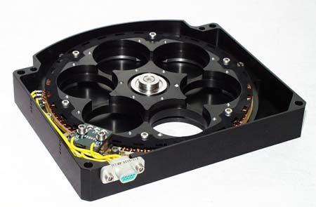
33 Current Optics Package 3D view - Scherrer 33
34 Optics Package Layout Current Layout Envelope (20 Mar 2003) X = 1114 mm Y = 285 mm Z = 696 mm Y X Z Origin - Scherrer 34
35 Electronics Box Layout SPARE CAMERA INTERFACE/BUFFER 7.7 in CAMERA INTERFACE/BUFFER 14.2 in COMPRESSOR/HIGH RATE INTERFACE A COMPRESSOR/HIGH RATE INTERFACE B LIMB TRACKER PZT DRIVERS MECHANISM & HEATER CONTROLLERS MECHANISM & HEATER CONTROLLERS MECHANISM & HEATER CONTROLLERS PCI/LOCAL BUS BRIDGE/1553 Interface 9.5 in Current Layout Envelope (20 Mar 2003) X = 361 mm Y = 241 mm Z = 234 mm HOUSEKEEPING DATA ACQUISITION RAD 6000/EEPROM Power supply adds 1.1 in in one dimension X Internal cabling for I/O connectors requires 3 in one dimension Y 9.2 in End View Z Top View Z - Scherrer 35
36 Resources Mass Estimates Mass no margin included 20 Mar 2003 Optics Package (OP, w/lmsal-ceb): 35.3 kg (TBC) Electronics Box (HEB): 15.0 kg (TBC) Harness: 3.0 kg (TBC) OP Assumptions Includes mass of redundant mechanisms in OP Includes larger OP for additional mechanisms, and ease of integration and alignment 1.5 kg mass reduction in OP possible if RAL CEBs are substituted HEB Assumptions Includes additional compression/high speed bus interface boards Includes thinned walls to account for spacecraft shielding 1 kg mass reduction in HEB power supply possible if RAL CEBs are substituted Does not include redundant power converters Harness Assumptions Harness mass presumes a length of 2 meters - Scherrer 36
37 Resources Inertias & CGs OP 20 Mar 2003 Ixx: 1.00 kg-m 2 (TBC) Iyy: 4.30 kg-m 2 (TBC) Izz: 3.48 kg-m 2 (TBC) these estimates are about the CG along OP axes so are therefore NOT principal axes, i.e. there are also some small inertia products CG (x,y,z) = 487 mm, 145 mm, 21 mm (TBC) HEB 20 Mar 2003 Ixx: 0.79 kg-m 2 (TBC) Iyy: 0.22 kg-m 2 (TBC) Izz: 0.97 kg-m 2 (TBC) these estimates presume the HEB is symmetrical about the center vertical axis so these are about principal axes through the CG, i.e. there are no inertia products CG (x,y,z) = 180 mm, 110 mm, 98 mm (TBC) - Scherrer 37
38 Resources - Average Power 20 Mar 2003 Operational Mode (1) Eclipse Mode (2) Survival Mode Early Ops (3) EB Electronics 30.5 W 30.5 W 0 0 OP Oven Control 1 W 1 W 0 0 OP Filter Oven 3 W 3 W 0 0 subtotal 34.5 W 34.5 W 0 0 PC Inefficiency 14.8 W 14.8 W 0 0 subtotal 49.3 W 49.3 W 0 0 Survival Heaters W 45 W CCD Decontam Heaters W Operational Heaters (4) 13 W 23 W 0 0 subtotal 62.3 W 72.3 W 45 W 67 W CEB (LMSAL) 30 W 30 W 0 0 Margin 15W 15W 9W 9W TOTAL W W 54 W 76 W 1 10 Watt reduction possible if RAL CEB is substituted 2 Preliminary allocation of 10 W additional heater power for window 3 CCD decontamination heaters only (TBC) 4 Operational heaters for OP, presume no power for HEB & CEB - Scherrer 38
39 Resources Mass Estimates Mass no margin included 20 Mar 2003 Optics Package (OP, w/lmsal-ceb): 35.3 kg (TBC) Electronics Box (HEB): 15.0 kg (TBC) Harness: 3.0 kg (TBC) OP Assumptions Includes mass of redundant mechanisms in OP Includes larger OP for additional mechanisms, and ease of integration and alignment 1.5 kg mass reduction in OP possible if RAL CEBs are substituted HEB Assumptions Includes additional compression/high speed bus interface boards Includes thinned walls to account for spacecraft shielding 1 kg mass reduction in HEB power supply possible if RAL CEBs are substituted Does not include redundant power converters Harness Assumptions Harness mass presumes a length of 2 meters - Scherrer 39
40 Resources - Telemetry Telemetry Data Rate Nominal science data: 55 Mbits/sec (Split between two interfaces) Housekeeping data: 2.5 kb/sec Diagnostics data: 10 kb/sec Command uplink: 2.6 kb/sec (max) - Scherrer 40
41 Spacecraft Resource Drivers Data Continuity & Completeness Capture 99.99% of the data (during 90 sec observing periods) Capture data 95% of all observing time Spacecraft Pointing & Stability The spacecraft shall maintain the reference boresight to within 200 arcsec of sun center The spacecraft shall maintain the roll reference to within TBD arcsec of solar North The spacecraft shall maintain drift of the spacecraft reference boresight relative to the reference boresight to within 14 arcsec in the Y and Z axes over a period not less than one week. The spacecraft jitter at the mounting interface to the optical bench shall be less than 5 arcsec (3 sigma) over frequencies of 0.02 Hz to 50 Hz in the X, Y and Z axes. Reference Time Spacecraft on-board time shall be accurate to 100 ms with respect to ground time (goal of 10 ms) - Scherrer 41
42 Heritage The primary heritage is the Michelson Doppler Imager instrument which has been successfully operating in space for over 7 years. Between launch in December 1995 and March 2003, almost 70 million exposures have been taken by MDI. Most of the sub-systems are based on designs developed for MDI and subsequent space instruments developed at LMSAL. Lyot filter has heritage from Spacelab-2/SOUP, SOHO/MDI, Solar-B/FPP instruments. Michelson interferometers will be very similar to the MDI Michelsons. Hollow core motors, filterwheel mechanisms, shutters and their controllers have been used in SOHO/MDI, TRACE, SXI, Epic/Triana, Solar-B/FPP, Solar-B/XRT, Stereo/SECCHI. The Image Stabilization System is very similar to the MDI design, and aspects of the ISS have been used in TRACE and Stereo/SECCHI. The main control processor planned for is being used on the SXI and Solar-B/FPP instruments. - Scherrer 42

43 Design Heritage The design is based on the successful Michelson Doppler Imager instrument. - Scherrer 43


44 Mechanisms Heritage - Scherrer 44
45 Technology Readiness Level - Scherrer 45
46 Assembly & Integration Flow Entrance filter Telescope structure Calibrate filter Integrate & align telescope Operations & Analysis Optics fabrication Lyot element fabrication Verify optics performance Assemble/align Lyot cells Assemble/cal. Lyot filter Fabricate optical elements Verify optics performance Fabricate Optics Package Launch & commissioning Michelsons fabrication Oven & controller fabrication Calibrate Michelsons Test oven & controller Assemble/test filter oven system Assemble & align on optical bench Assemble & align in optics package Spacecraft I&T calibration Fabricate mechanisms Test mechanisms environmental test Fabricate focal plane Integrate focal plane Calibrate focal plane Test & calibrate ISS Integrate electronics, software, & OP functional test CCD detector Camera electronics Fabricate ISS Fabricate electronics Develop Software - Scherrer 46
47 Environmental Test Approach In general environmental test will be done at the integrated level to protoflight levels & durations The preferred order of testing is: LFFT SPT for Calibration SPT for Sunlight Performance EMI/EMC LFFT Sine & Random Vibration Electronics & Optics Package separately Powered off LFFT Thermal Vacuum / Thermal Balance LFFT SPT for Calibration SPT for Sunlight Performance in vacuum Mass Properties Delivery - Scherrer 47
48 Instrument Calibration Approach Critical subsystems will be calibrated at LMSAL prior to integration these include The CCD cameras The Michelsons The Lyot filter Mechanisms Other optical elements The completed will be calibrated at LMSAL using lasers, the stimulus telescope and the Sun The completed will be calibrated at LMSAL in vacuum using both the stimulus telescope and the Sun - Scherrer 48
49 Functional Test Approach will use a structured test approach so that the test at each point in the program can be appropriate to the need and consistent test results can be obtained The tests will be controlled by STOL procedures running in the EGSE and will use released test procedures The Aliveness test will run in less than 30 minutes and will do a quick test of the major subsystems The Short Form Functional Test (SFFT) will run in a few hours and will test all subsystems but will not test all modes or paths. It will not require the stimulus telescope The Long Form Functional Test (LFFT) will run in about 8 hours and will attempt to cover all paths and major modes. The SFFT is a subset of the LFFT. The LFFT will require the use of the stimulus telescope Special Performance Tests (SPT) are tests that measure a specific aspect of the performance. These are detailed test that require the stimulus telescope or other special setups. They are used only a few times in the program - Scherrer 49
50 Functional Test on Observatory SFFT / LFFT / SPT are derived from Instrument level tests We assume that GSFC will provide an interface to the EGSE so the same EGSE system can be used to test after integration onto the spacecraft We will use the stimulus telescope to verify calibration while is mounted on the spacecraft We recommend the inclusion of a spacecraft level jitter compatibility test - Scherrer 50
51 Schedule and Critical Path - Scherrer 51
52 Risks Assessment Instrument Development Filter performance: The Lyot filter and Michelson interferometers are the heart of the instrument. Although we have previously built these filters for the MDI instrument, there are relatively few vendors with the specialized skills necessary for their fabrication. We are working aggressively to develop detailed filter specifications and identify potential vendors. Mechanisms longevity : Although the hollow core motor and shutter planned for have significant flight heritage, the required number of mechanism moves is of concern. Lifetests of the hollow core motors and shutters are planned to validate their performance for the planned SDO mission duration. Thermal performance: The thermal stability of the instrument is critical to achieving it s ultimate performance. Detailed thermal modeling and subsystem thermal testing will be used to optimize the thermal design. - Scherrer 52
53 Risks Assessment - Programmatic camera electronics has potential schedule/cost impact: Obtaining SECHHI derived camera electronics from the Rutherford Appleton Laboratory in the UK is a viable option for, but the development schedule is not know in detail. If this option is chosen, we feel it is best that we obtain the camera electronics directly from RAL. A modified Solar-B/FPP camera electronics developed by LMSAL will also meet the requirements. This option has less schedule risk, but costs and camera power and mass are higher than the RAL camera. Timely negotiation of Product Assurance Implementation Plan - Scherrer 53
Solar Dynamics Observatory. Solar Dynamics Observatory. System Concept Review Helioseismic and Magnetic Imager
 Solar Dynamics Observatory Solar Dynamics Observatory System Concept Review Helioseismic and Magnetic Imager Presenters: P. Scherrer R. Bush L. Springer Stanford University Hansen Experimental Physics
Solar Optical Telescope (SOT)
") Solar Optical Telescope (SOT) The Solar-B Solar Optical Telescope (SOT) will be the largest telescope with highest performance ever to observe the sun from space. The telescope itself (the so-called Optical
Solar Optical Telescope (SOT) The Solar-B Solar Optical Telescope (SOT) will be the largest telescope with highest performance ever to observe the sun from space. The telescope itself (the so-called Optical
Monthly Progress Report April 2004
 Heliosiesmic & Magnetic Imager Contract #: PY-2223 Cage Code: 65113 Total Pages: 7 Monthly Progress Report April 2004 Lockheed Martin Space Systems Company Advanced Technology Center Lockheed Martin Solar
Helioseismic Magnetic Imager Program at LMSAL
 Helioseismic Magnetic Imager Program at LMSAL Contract PY-2223 Progress Report for December 2002 Introduction This is the third monthly progress report for the HMI program at LMSAL. We/LMSAL are collaborators
Helioseismic and Magnetic Imager for Solar Dynamics Observatory
 Helioseismic and Magnetic Imager for Solar Dynamics Observatory Concept Study Report Appendix B Instrument Performance Document SU-HMI-S013 2 July 2003 Stanford University Hansen Experimental Physics Laboratory
The Helioseismic and Magnetic Imager Instrument Design and Calibration
 Solar Physics DOI: 10.1007/ - - - - The Helioseismic and Magnetic Imager Instrument Design and Calibration J. Schou 1 P. H. Scherrer 1 R. Wachter 1 S. Couvidat 1 R. I. Bush 1 M. C. Rabello-Soares 1 Y.
A LATERAL SENSOR FOR THE ALIGNMENT OF TWO FORMATION-FLYING SATELLITES
 A LATERAL SENSOR FOR THE ALIGNMENT OF TWO FORMATION-FLYING SATELLITES S. Roose (1), Y. Stockman (1), Z. Sodnik (2) (1) Centre Spatial de Liège, Belgium (2) European Space Agency - ESA/ESTEC slide 1 Outline
Coronal and heliospheric imaging instrumentation development at RAL Space
 Coronal and heliospheric imaging instrumentation development at RAL Space JA Davies, CJ Eyles, DK Griffin, RA Harrison, KF Middleton, AG Richards, JK Rogers, SJ Tappin, IAJ Tosh, NR Waltham Heritage (1)
OPAL Optical Profiling of the Atmospheric Limb
 OPAL Optical Profiling of the Atmospheric Limb Alan Marchant Chad Fish Erik Stromberg Charles Swenson Jim Peterson OPAL STEADE Mission Storm Time Energy & Dynamics Explorers NASA Mission of Opportunity
Condensing Solar X-ray and EUV Flare and Coronal Dimming Information Down to a Few Bytes for Lagrange-Point Space Weather Missions
 Condensing Solar X-ray and EUV Flare and Coronal Dimming Information Down to a Few Bytes for Lagrange-Point Space Weather Missions Tom Woods, Frank Eparvier, Andrew Jones, James Mason University of Colorado
CIRiS: Compact Infrared Radiometer in Space August, 2017
 1 CIRiS: Compact Infrared Radiometer in Space August, 2017 David Osterman PI, CIRiS Mission Presented by Hansford Cutlip 10/8/201 7 Overview of the CIRiS instrument and mission The CIRiS instrument is
Design of a Free Space Optical Communication Module for Small Satellites
 Design of a Free Space Optical Communication Module for Small Satellites Ryan W. Kingsbury, Kathleen Riesing Prof. Kerri Cahoy MIT Space Systems Lab AIAA/USU Small Satellite Conference August 6 2014 Problem
Development of a Low-order Adaptive Optics System at Udaipur Solar Observatory
 J. Astrophys. Astr. (2008) 29, 353 357 Development of a Low-order Adaptive Optics System at Udaipur Solar Observatory A. R. Bayanna, B. Kumar, R. E. Louis, P. Venkatakrishnan & S. K. Mathew Udaipur Solar
Solar Activity Investigation (SAI): a 6U CubeSat mission concept
: a 6U CubeSat mission concept") Solar Activity Investigation (SAI): a 6U CubeSat mission concept Neil Murphy 1, Stuart Jefferies 2, Bernhard Fleck 3, Francesco Berrilli 4, Marco Velli 5, Glenn Lightsey 6, Laurent Gizon 7, Doug Braun
Solar Activity Investigation (SAI): a 6U CubeSat mission concept Neil Murphy 1, Stuart Jefferies 2, Bernhard Fleck 3, Francesco Berrilli 4, Marco Velli 5, Glenn Lightsey 6, Laurent Gizon 7, Doug Braun
The Nemo Bus: A Third Generation Nanosatellite Bus for Earth Monitoring and Observation
 The Nemo Bus: A Third Generation Nanosatellite Bus for Earth Monitoring and Observation FREDDY M. PRANAJAYA Manager, Advanced Systems Group S P A C E F L I G H T L A B O R A T O R Y University of Toronto
SONG Stellar Observations Network Group. The prototype
 SONG Stellar Observations Network Group The prototype F. Grundahl1, J. Christensen Dalsgaard1, U. G. Jørgensen2, H. Kjeldsen1,S. Frandsen1 and P. Kjærgaard2 1) Danish AsteroSeismology Centre, University
GPI INSTRUMENT PAGES
 GPI INSTRUMENT PAGES This document presents a snapshot of the GPI Instrument web pages as of the date of the call for letters of intent. Please consult the GPI web pages themselves for up to the minute
1.6 Beam Wander vs. Image Jitter
 8 Chapter 1 1.6 Beam Wander vs. Image Jitter It is common at this point to look at beam wander and image jitter and ask what differentiates them. Consider a cooperative optical communication system that
Inverted-COR: Inverted-Occultation Coronagraph for Solar Orbiter
 Inverted-COR: Inverted-Occultation Coronagraph for Solar Orbiter OATo Technical Report Nr. 119 Date 19-05-2009 by: Silvano Fineschi Release Date Sheet: 1 of 1 REV/ VER LEVEL DOCUMENT CHANGE RECORD DESCRIPTION
NIRCam optical calibration sources
 NIRCam optical calibration sources Stephen F. Somerstein, Glen D. Truong Lockheed Martin Advanced Technology Center, D/ABDS, B/201 3251 Hanover St., Palo Alto, CA 94304-1187 ABSTRACT The Near Infrared
The Asteroid Finder Focal Plane
 The Asteroid Finder Focal Plane H. Michaelis (1), S. Mottola (1), E. Kührt (1), T. Behnke (1), G. Messina (1), M. Solbrig (1), M. Tschentscher (1), N. Schmitz (1), K. Scheibe (2), J. Schubert (3), M. Hartl
CaSSIS. Colour and Stereo Surface Imaging System. L. Gambicorti & CaSSIS team
 CaSSIS Colour and Stereo Surface Imaging System & CaSSIS team CaSSIS on Exomars TGO l l Introduction CaSSIS: stereo-colour camera Telescope and Optical configuration Best focus on ground CaSSIS integration
Optical Telescope Design Study Results
 Optical Telescope Design Study Results 10 th International LISA Symposium Jeff Livas 20 May 2014 See also poster #19: Shannon Sankar UF and GSFC Telescope Design for a Space-based Gravitational-wave Mission
THE OFFICINE GALILEO DIGITAL SUN SENSOR
 THE OFFICINE GALILEO DIGITAL SUN SENSOR Franco BOLDRINI, Elisabetta MONNINI Officine Galileo B.U. Spazio- Firenze Plant - An Alenia Difesa/Finmeccanica S.p.A. Company Via A. Einstein 35, 50013 Campi Bisenzio
Low Cost Earth Sensor based on Oxygen Airglow
 Assessment Executive Summary Date : 16.06.2008 Page: 1 of 7 Low Cost Earth Sensor based on Oxygen Airglow Executive Summary Prepared by: H. Shea EPFL LMTS herbert.shea@epfl.ch EPFL Lausanne Switzerland
Holography Transmitter Design Bill Shillue 2000-Oct-03
 Holography Transmitter Design Bill Shillue 2000-Oct-03 Planned Photonic Reference Distribution for Test Interferometer The transmitter for the holography receiver is made up mostly of parts that are already
A 1m Resolution Camera For Small Satellites
 A 1m Resolution Camera For Small Satellites Paper SSC06-X-5 Presenter: Jeremy Curtis 1 Introduction TopSat launched October 2005 carrying RAL s 2.5m GSD camera into a 686km orbit Built and operated by
Michigan Multipurpose MiniSat M-Cubed. Kiril Dontchev Summer CubeSat Workshop: 8/9/09
 Michigan Multipurpose MiniSat M-Cubed Kiril Dontchev Summer CubeSat Workshop: 8/9/09 Michigan NanoSat Pipeline Inputs Outputs U of M Ideas Innovative technology Entrepreneurial thought Science Papers Flight
Attitude Determination and Control Specifications
 Attitude Determination and Control Specifications 1. SCOPE The attitude determination and control sub system will passively control the orientation of the two twin CubeSats. 1.1 General. This specification
Radiometric Solar Telescope (RaST) The case for a Radiometric Solar Imager,
 The case for a Radiometric Solar Imager,") SORCE Science Meeting 29 January 2014 Mark Rast Laboratory for Atmospheric and Space Physics University of Colorado, Boulder Radiometric Solar Telescope (RaST) The case for a Radiometric Solar Imager,
SORCE Science Meeting 29 January 2014 Mark Rast Laboratory for Atmospheric and Space Physics University of Colorado, Boulder Radiometric Solar Telescope (RaST) The case for a Radiometric Solar Imager,
CCD Procurement Specification EUV Imaging Spectrometer
 Solar-B EIS * CCD Procurement Specification EUV Imaging Spectrometer Title CCD Procurement specification Doc ID MSSL/SLB-EIS/SP/02 ver 2.0 Author Chris McFee Date 25 March 2001 Ver 2.0 Page 2 of 10 Contents
B ==================================== C
 Satellite Space Segment Communication Frequencies Frequency Band (GHz) Band Uplink Crosslink Downlink Bandwidth ==================================== C 5.9-6.4 3.7 4.2 0.5 X 7.9-8.4 7.25-7.7575 0.5 Ku 14-14.5
Spacecraft to Science Instrument Data Interface Control Document. Dwg. No
 Rev. ECO Description Checked Approval Date 01 Initial Release for S/C negotiation RFGoeke 4 Oct.02 Spacecraft to Science Instrument Data Interface Control Document Dwg. No. 43-03001 Revision 01 4 October
CU-LASP Test Facilities! and Instrument Calibration Capabilities"
 CU-LASP Test Facilities! and Instrument Calibration Capabilities" Ginger Drake Calibration Group Manager 303-492-5899 Ginger.Drake@lasp.colorado.edu Thermal Vacuum Test Facilities" 2 Multiple Optical Beam
NIRCAM PUPIL IMAGING LENS MECHANISM AND OPTICAL DESIGN
 NIRCAM PUPIL IMAGING LENS MECHANISM AND OPTICAL DESIGN Charles S. Clark and Thomas Jamieson Lockheed Martin Advanced Technology Center ABSTRACT The Near Infrared Camera (NIRCam) instrument for NASA s James
AIAA/USU Small Satellite Conference 2007 Paper No. SSC07-VIII-2
 Digital Imaging Space Camera (DISC) Design & Testing Mitch Whiteley Andrew Shumway, Presenter Quinn Young Robert Burt Jim Peterson Jed Hancock James Peterson AIAA/USU Small Satellite Conference 2007 Paper
Comments for a preliminary EIS science plan
 Comments for a preliminary EIS science plan H. Hara 2005 Oct 31 For the science meeting at ISAS Observables Line intensity w Line shift by Doppler motion Line width motion temperature, nonthermal Information
CubeSat Proximity Operations Demonstration (CPOD) Vehicle Avionics and Design
 Vehicle Avionics and Design") CubeSat Proximity Operations Demonstration (CPOD) Vehicle Avionics and Design August CubeSat Workshop 2015 Austin Williams VP, Space Vehicles CPOD: Big Capability in a Small Package Communications ADCS
CubeSat Proximity Operations Demonstration (CPOD) Vehicle Avionics and Design August CubeSat Workshop 2015 Austin Williams VP, Space Vehicles CPOD: Big Capability in a Small Package Communications ADCS
Power modeling and budgeting design and validation with in-orbit data of two commercial LEO satellites
 SSC17-X-08 Power modeling and budgeting design and validation with in-orbit data of two commercial LEO satellites Alan Kharsansky Satellogic Av. Raul Scalabrini Ortiz 3333 piso 2, Argentina; +5401152190100
Calibration considerations for a reduced-timeline optimized approach for VNIR earthorbiting
 Calibration considerations for a reduced-timeline optimized approach for VNIR earthorbiting satellites Zachary Bergen, Joe Tansock Space Dynamics Laboratory 1695 North Research Park Way, North Logan, UT
SIMBOL-X. Peter Lechner MPI-HLL Project Review Schloss Ringberg, science background. mission. telescope.
 SIMBOL-X Peter Lechner MPI-HLL Project Review Schloss Ringberg, 24.04.07 science background mission telescope detector payload low energy detector science background science targets black holes astrophysics
Difrotec Product & Services. Ultra high accuracy interferometry & custom optical solutions
 Difrotec Product & Services Ultra high accuracy interferometry & custom optical solutions Content 1. Overview 2. Interferometer D7 3. Benefits 4. Measurements 5. Specifications 6. Applications 7. Cases
Design parameters Summary
 634 Entrance pupil diameter 100-m Entrance pupil location Primary mirror Exit pupil location On M6 Focal ratio 6.03 Plate scale 2.924 mm / arc second (on-axis) Total field of view 10 arc minutes (unvignetted)
erosita mirror calibration:
 erosita mirror calibration: First measurements and future concept PANTER instrument chamber set-up for XMM mirror calibration: 12 m length, 3.5 m diameter: 8m to focal plane instrumentation now: f = 1.6
Meteosat Third Generation (MTG) Lightning Imager (LI) instrument on-ground and in-flight calibration
 Lightning Imager (LI) instrument on-ground and in-flight calibration") Meteosat Third Generation (MTG) Lightning Imager (LI) instrument on-ground and in-flight calibration Marcel Dobber, Stephan Kox EUMETSAT (Darmstadt, Germany) 1 Contents of this presentation Meteosat Third
Meteosat Third Generation (MTG) Lightning Imager (LI) instrument on-ground and in-flight calibration Marcel Dobber, Stephan Kox EUMETSAT (Darmstadt, Germany) 1 Contents of this presentation Meteosat Third
From Single to Formation Flying CubeSats: An Update of the Delfi Programme
 From Single to Formation Flying CubeSats: An Update of the Delfi Programme Jian Guo, Jasper Bouwmeester & Eberhard Gill 1 Outline Introduction Delfi-C 3 Mission Delfi-n3Xt Mission Lessons Learned DelFFi
NIRCam Instrument Overview
 NIRCam Instrument Overview Larry G. Burriesci Lockheed Martin Advanced Technology Center 3251 Hanover St., Palo Alto, CA 94304 ABSTRACT The Near Infrared (NIRCam) instrument for NASA s James Webb Space
A CubeSat Radio Beacon Experiment
 A CubeSat Radio Beacon Experiment CUBEACON A Beacon Test of Designs for the Future Antenna? Michael Cousins SRI International Multifrequency? Size, Weight and Power? CubeSat Developers Workshop, April
FLCS V2.1. AHRS, Autopilot, Gyro Stabilized Gimbals Control, Ground Control Station
 AHRS, Autopilot, Gyro Stabilized Gimbals Control, Ground Control Station The platform provides a high performance basis for electromechanical system control. Originally designed for autonomous aerial vehicle
APPROVAL SHEET. TITLE : Prime Focus Image Spectrograph (PFIS) ICD of the Southern African Large Telescope (SALT)
 ICD of the Southern African Large Telescope (SALT)") APPROVAL SHEET TITLE : Prime Focus Image Spectrograph (PFIS) ICD of the Southern African Large Telescope (SALT) DOCUMENT NUMBER : 1520AS0002 ISSUE: 3 SYNOPSIS : This document describes the Interface between
APPROVAL SHEET TITLE : Prime Focus Image Spectrograph (PFIS) ICD of the Southern African Large Telescope (SALT) DOCUMENT NUMBER : 1520AS0002 ISSUE: 3 SYNOPSIS : This document describes the Interface between
PAPER NUMBER: PAPER TITLE: Multi-band CMOS Sensor simplify FPA design. SPIE, Remote sensing 2015, Toulouse, France.
 PAPER NUMBER: 9639-28 PAPER TITLE: Multi-band CMOS Sensor simplify FPA design to SPIE, Remote sensing 2015, Toulouse, France On Section: Sensors, Systems, and Next-Generation Satellites Page1 Multi-band
Stereoscopic Magnetography with SHAZAM
 Stereoscopic Magnetography with SHAZAM (Solar High-speed Zeeman Magnetograph) Craig DeForest Southwest Research Institute Summary of talk What and why is SHAZAM? How does a stereoscopic magnetograph work?
CubeSat-Scale Hyperspectral Imager for Middle Atmosphere Investigations
 CubeSat-Scale Hyperspectral Imager for Middle Atmosphere Investigations Rick Doe 1, Steve Watchorn 2, John Noto 2, Robert Kerr 2, Karl van Dyk 1, Kyle Leveque 1, and Christopher Sioris 3 1 SRI International
High Speed, Low Cost Telemetry Access from Space Development Update on Programmable Ultra Lightweight System Adaptable Radio (PULSAR)
") High Speed, Low Cost Telemetry Access from Space Development Update on Programmable Ultra Lightweight System Adaptable Radio (PULSAR) Herb Sims, Kosta Varnavas, Eric Eberly (MSFC) Presented By: Leroy Hardin
High Speed, Low Cost Telemetry Access from Space Development Update on Programmable Ultra Lightweight System Adaptable Radio (PULSAR) Herb Sims, Kosta Varnavas, Eric Eberly (MSFC) Presented By: Leroy Hardin
Presented by Jerry Hubbell Lake of the Woods Observatory (MPC I24) President, Rappahannock Astronomy Club
 President, Rappahannock Astronomy Club") Presented by Jerry Hubbell Lake of the Woods Observatory (MPC I24) President, Rappahannock Astronomy Club ENGINEERING A FIBER-FED FED SPECTROMETER FOR ASTRONOMICAL USE Objectives Discuss the engineering
Presented by Jerry Hubbell Lake of the Woods Observatory (MPC I24) President, Rappahannock Astronomy Club ENGINEERING A FIBER-FED FED SPECTROMETER FOR ASTRONOMICAL USE Objectives Discuss the engineering
Mission Overview ELECTRON LOSSES AND FIELDS INVESTIGATION CubeSat Developers Workshop. University of California, Los Angeles April 25, 2013
 ELECTRON LOSSES AND FIELDS INVESTIGATION Mission Overview 2013 CubeSat Developers Workshop University of California, Los Angeles April 25, 2013 elfin@igpp.ucla.edu 1 Electron Losses and Fields Investigation
Exercise 8: Interference and diffraction
 Physics 223 Name: Exercise 8: Interference and diffraction 1. In a two-slit Young s interference experiment, the aperture (the mask with the two slits) to screen distance is 2.0 m, and a red light of wavelength
IT-SPINS Ionospheric Imaging Mission
 IT-SPINS Ionospheric Imaging Mission Rick Doe, SRI Gary Bust, Romina Nikoukar, APL Dave Klumpar, Kevin Zack, Matt Handley, MSU 14 th Annual CubeSat Dveloper s Workshop 26 April 2017 IT-SPINS Ionosphere-Thermosphere
Puntino. Shack-Hartmann wavefront sensor for optimizing telescopes. The software people for optics
 Puntino Shack-Hartmann wavefront sensor for optimizing telescopes 1 1. Optimize telescope performance with a powerful set of tools A finely tuned telescope is the key to obtaining deep, high-quality astronomical
Figure 1. Proposed Mission Operations Functions. Key Performance Parameters Success criteria of an amateur communicator on board of Moon-exploration
 Title: CubeSat amateur laser communicator with Earth to Moon orbit data link capability Primary Point of Contact (POC) & email: oregu.nijuniku@jaxa.jp Co-authors: Oleg Nizhnik Organization: JAXA Need Available
Use of the Deep Impact HRI Instrument to Observe Exoplanets Via Microlensing
 Use of the Deep Impact HRI Instrument to Observe Exoplanets Via Microlensing 16 th International Conference on Gravitational Microlensing Steve Wissler [1] David Bennett [2] Tim Larson [1] [1] Jet Propulsion
EPS Bridge Low-Cost Satellite
 EPS Bridge Low-Cost Satellite Results of a Concept Study being performed for Dr. Hendrik Lübberstedt OHB-System AG OpSE Workshop Walberberg 8th November 2005 EPS Bridge Key System Requirements Minimum
Using Machine Vision Cameras for Solar Imaging. Dr Stuart Green
 Using Machine Vision Cameras for Solar Imaging Dr Stuart Green Hubble Ultra-deep Field Image Estimated 100 billion galaxies in the observable universe Estimated 200-400 billion stars in our own galaxy
Selecting an image sensor for the EJSM VIS/NIR camera systems
 Selecting an image sensor for the EJSM VIS/NIR camera systems presented by Harald Michaelis (DLR-PF) Folie 1 EJSM- Jan. 18th 2010; ESTEC What for a detector/sensor we shall chose for EJSM? Vortragstitel
An integral eld spectrograph for the 4-m European Solar Telescope
 Mem. S.A.It. Vol. 84, 416 c SAIt 2013 Memorie della An integral eld spectrograph for the 4-m European Solar Telescope A. Calcines 1,2, M. Collados 1,2, and R. L. López 1 1 Instituto de Astrofísica de Canarias
YamSat. YamSat Introduction. YamSat Team Albert Lin (NSPO) Yamsat website
 Yamsat website") Introduction Team Albert Lin (NSPO) Yamsat website http://www.nspo.gov.tw Major Characteristics Mission: Y: Young, developed by young people. A: Amateur Radio Communication M: Micro-spectrometer payload
Introduction Team Albert Lin (NSPO) Yamsat website http://www.nspo.gov.tw Major Characteristics Mission: Y: Young, developed by young people. A: Amateur Radio Communication M: Micro-spectrometer payload
Utilizing Commercial DSLR for High Resolution Earth Observation Satellite
 SSC18-XII-03 Utilizing Commercial DSLR for High Resolution Earth Observation Satellite Nobutada Sako Canon Electronics Inc. 3-5-10, Shibakoen, Minato-ku, Tokyo 105-0011, Japan; +81-3-6910-1105 sako.nobutada@canon-elec.co.jp
PREPARED BY: I. Miller DATE: 2004 May 23 CO-OWNERS REVISED DATE OF ISSUE/CHANGED PAGES
 Page 1 of 34 LIGHTMACHINERY TEST REPORT LQT 30.11-3 TITLE: HMI Michelson Interferometer Test Report Serial Number 3 wide band FSR INSTRUCTION OWNER HMI Project Manager PREPARED BY: I. Miller DATE: 2004
Chapter 3 Solution to Problems
 Chapter 3 Solution to Problems 1. The telemetry system of a geostationary communications satellite samples 100 sensors on the spacecraft in sequence. Each sample is transmitted to earth as an eight-bit
Peregrine: A deployable solar imaging CubeSat mission
 Peregrine: A deployable solar imaging CubeSat mission C1C Samantha Latch United States Air Force Academy d 20 April 2012 CubeSat Workshop Air Force Academy U.S. Air Force Academy Colorado Springs Colorado,
CubeSat Proximity Operations Demonstration (CPOD) Mission Update Cal Poly CubeSat Workshop San Luis Obispo, CA
 Mission Update Cal Poly CubeSat Workshop San Luis Obispo, CA") CubeSat Proximity Operations Demonstration (CPOD) Mission Update Cal Poly CubeSat Workshop San Luis Obispo, CA 04-22-2015 Austin Williams VP, Space Vehicles ConOps Overview - Designed to Maximize Mission
CubeSat Proximity Operations Demonstration (CPOD) Mission Update Cal Poly CubeSat Workshop San Luis Obispo, CA 04-22-2015 Austin Williams VP, Space Vehicles ConOps Overview - Designed to Maximize Mission
Southern African Large Telescope. Prime Focus Imaging Spectrograph. Instrument Acceptance Testing Plan
 Southern African Large Telescope Prime Focus Imaging Spectrograph Instrument Acceptance Testing Plan Eric B. Burgh University of Wisconsin Document Number: SALT-3160AP0003 Revision 2.2 29 April 2004 1
Spatially Resolved Backscatter Ceilometer
 Spatially Resolved Backscatter Ceilometer Design Team Hiba Fareed, Nicholas Paradiso, Evan Perillo, Michael Tahan Design Advisor Prof. Gregory Kowalski Sponsor, Spectral Sciences Inc. Steve Richstmeier,
AMIPAS. Advanced Michelson Interferometer for Passive Atmosphere Sounding. Concepts and Technology for Future Atmospheric Chemistry Sensors
 Earth Observation, Navigation & Science Concepts and Technology for Future Atmospheric Chemistry Sensors AMIPAS Advanced Michelson Interferometer for Passive Atmosphere Sounding Markus Melf, Winfried Posselt,
4DAD, a device to align angularly and laterally a high power laser using a conventional sighting telescope as metrology
 4DAD, a device to align angularly and laterally a high power laser using a conventional sighting telescope as metrology Christophe DUPUY, Thomas PFROMMER, Domenico BONACCINI CALIA European Southern Observatory,
University of Kentucky Space Systems Laboratory. Jason Rexroat Space Systems Laboratory University of Kentucky
 University of Kentucky Space Systems Laboratory Jason Rexroat Space Systems Laboratory University of Kentucky September 15, 2012 Missions Overview CubeSat Capabilities Suborbital CubeSats ISS CubeSat-sized
LISA and SMART2 Optical Work in Europe
 LISA and SMART2 Optical Work in Europe David Robertson University of Glasgow Outline Overview of current optical system work Title Funded by Main focus Prime Phase Measuring System LISA SMART2 SEA (Bristol)
Polarization Controllers. Firebird TM Product range information
 Polarization Controllers Firebird TM Product range information Phoenix Fiber Polarization Controllers Customer information note Overview Phoenix polarization range of controllers is all-fiber offering
MONS Field Monitor. System Definition Phase. Design Report
 Field Monitor System Definition Phase Design Report _AUS_PL_RP_0002(1) Issue 1 11 April 2001 Prepared by Date11 April 2001 Chris Boshuizen and Leigh Pfitzner Checked by Date11 April 2001 Tim Bedding Approved
HEMERA Constellation of passive SAR-based micro-satellites for a Master/Slave configuration
 HEMERA Constellation of passive SAR-based micro-satellites for a Master/Slave HEMERA Team Members: Andrea Bellome, Giulia Broggi, Luca Collettini, Davide Di Ienno, Edoardo Fornari, Leandro Lucchese, Andrea
Satellite Technology for Future Applications
 Satellite Technology for Future Applications WSRF Panel n 4 Dubai, 3 March 2010 Guy Perez VP Telecom Satellites Programs 1 Commercial in confidence / All rights reserved, 2010, Thales Alenia Space Content
PREPARED BY: I. Miller DATE: 2004 May 23 CO-OWNERS REVISED DATE OF ISSUE/CHANGED PAGES
 Page 1 of 30 LIGHTMACHINERY TEST REPORT LQT 30.11-1 TITLE: HMI Michelson Interferometer Test Report Serial Number 1 - Wideband FSR INSTRUCTION OWNER HMI Project Manager PREPARED BY: I. Miller DATE: 2004
A LARGE COMBINATION HORIZONTAL AND VERTICAL NEAR FIELD MEASUREMENT FACILITY FOR SATELLITE ANTENNA CHARACTERIZATION
 A LARGE COMBINATION HORIZONTAL AND VERTICAL NEAR FIELD MEASUREMENT FACILITY FOR SATELLITE ANTENNA CHARACTERIZATION John Demas Nearfield Systems Inc. 1330 E. 223rd Street Bldg. 524 Carson, CA 90745 USA
MICROSCOPE Mission operational concept
 MICROSCOPE Mission operational concept PY. GUIDOTTI (CNES, Microscope System Manager) January 30 th, 2013 1 Contents 1. Major points of the operational system 2. Operational loop 3. Orbit determination
Science Detectors for E-ELT Instruments. Mark Casali
 Science Detectors for E-ELT Instruments Mark Casali 1 The Telescope Nasmyth telescope with a segmented primary mirror. Novel 5 mirror design to include adaptive optics in the telescope. Classical 3mirror
Instrument Characteristics
 II Workshop Instrument Characteristics Marco Romoli Torino, 12-13 dicembre 2012 In order to meet the requirements: Coronal Imaging Wavelength range Spatial Resolution Field-of-view VL: 580-640 nm UV: 121.6
Compact High Resolution Imaging Spectrometer (CHRIS) siraelectro-optics
 siraelectro-optics") Compact High Resolution Imaging Spectrometer (CHRIS) Mike Cutter (Mike_Cutter@siraeo.co.uk) Summary CHRIS Instrument Design Instrument Specification & Performance Operating Modes Calibration Plan Data
Compact High Resolution Imaging Spectrometer (CHRIS) Mike Cutter (Mike_Cutter@siraeo.co.uk) Summary CHRIS Instrument Design Instrument Specification & Performance Operating Modes Calibration Plan Data
A CubeSat-Based Optical Communication Network for Low Earth Orbit
 A CubeSat-Based Optical Communication Network for Low Earth Orbit Richard Welle, Alexander Utter, Todd Rose, Jerry Fuller, Kristin Gates, Benjamin Oakes, and Siegfried Janson The Aerospace Corporation
The DECam System: Technical Characteristics
 The DECam System: Technical Characteristics Alistair R. Walker DECam Instrument Scientist DECam Community Workshop 1 Contents Status & Statistics A selective look at some DECam & Blanco technical properties
Airbus DS ESA Phase-0 L5 Spacecraft/Orbital Concept Overview. Emanuele Monchieri 6 th March 2017
 Airbus DS ESA Phase-0 L5 Spacecraft/Orbital Concept Overview Emanuele Monchieri 6 th March 2017 Airbus DS ESA Phase-0 L5 Spacecraft/Orbital Concept Overview Contents L5 Mission Outline Mission Concept
WFC3 SMOV Proposal 11422/ 11529: UVIS SOFA and Lamp Checks
 WFC3 SMOV Proposal 11422/ 11529: UVIS SOFA and Lamp Checks S.Baggett, E.Sabbi, and P.McCullough November 12, 2009 ABSTRACT This report summarizes the results obtained from the SMOV SOFA (Selectable Optical
Deep- Space Optical Communication Link Requirements
 Deep- Space Optical Communication Link Requirements Professor Chester S. Gardner Department of Electrical and Computer Engineering University of Illinois cgardner@illinois.edu Link Equation: For a free-
Lecture 04: Solar Imaging Instruments
 Hale COLLAGE (NJIT Phys-780) Topics in Solar Observation Techniques Lecture 04: Solar Imaging Instruments Wenda Cao New Jersey Institute of Technology Valentin M. Pillet National Solar Observatory SDO
Chapter 2 Satellite Configuration Design
 Chapter 2 Satellite Configuration Design Abstract This chapter discusses the process of integration of the subsystem components and development of the satellite configuration to achieve a final layout
PREPARED BY: I. Miller DATE: 2004 May 23 CO-OWNERS REVISED DATE OF ISSUE/CHANGED PAGES
 Page 1 of 30 LIGHTMACHINERY TEST REPORT LQT 30.11-2 TITLE: HMI Michelson Interferometer Test Report Serial Number 2 - Narrowband FSR INSTRUCTION OWNER HMI Project Manager PREPARED BY: I. Miller DATE: 2004
Department of Mechanical and Aerospace Engineering, Princeton University Department of Astrophysical Sciences, Princeton University ABSTRACT
 Phase and Amplitude Control Ability using Spatial Light Modulators and Zero Path Length Difference Michelson Interferometer Michael G. Littman, Michael Carr, Jim Leighton, Ezekiel Burke, David Spergel
Deep Space Communication The further you go, the harder it gets. D. Kanipe, Sept. 2013
 Deep Space Communication The further you go, the harder it gets D. Kanipe, Sept. 2013 Deep Space Communication Introduction Obstacles: enormous distances, S/C mass and power limits International Telecommunications
EE119 Introduction to Optical Engineering Spring 2003 Final Exam. Name:
 EE119 Introduction to Optical Engineering Spring 2003 Final Exam Name: SID: CLOSED BOOK. THREE 8 1/2 X 11 SHEETS OF NOTES, AND SCIENTIFIC POCKET CALCULATOR PERMITTED. TIME ALLOTTED: 180 MINUTES Fundamental
The Wide Field Imager
 Athena Kickoff Meeting Garching, 29.January 2014 The Wide Field Imager Norbert Meidinger, Athena WFI project leader WFI Flight Hardware Architecture (1 st Draft) DEPFET APS Concept Active pixel sensor
instruments Solar Physics course lecture 3 May 4, 2010 Frans Snik BBL 415 (710)
") Solar Physics course lecture 3 May 4, 2010 Frans Snik BBL 415 (710) f.snik@astro.uu.nl www.astro.uu.nl/~snik info from photons spatial (x,y) temporal (t) spectral (λ) polarization ( ) usually photon starved
Solar Physics course lecture 3 May 4, 2010 Frans Snik BBL 415 (710) f.snik@astro.uu.nl www.astro.uu.nl/~snik info from photons spatial (x,y) temporal (t) spectral (λ) polarization ( ) usually photon starved