Measuring the throughput in spectrographs
|
|
|
- Imogene Fisher
- 5 years ago
- Views:
Transcription
1 Measuring the throughput in spectrographs By Gerardo Avila & Carlos Guirao CAOS ( 1 St. Niklausen - ASpekt 2017
2 CAOS group Gerardo Avila Vadim Burwitz Carlos Guirao Jesús Rodriguez 2 St. Niklausen - ASpekt 2017
3 Purposes of our presentation The spectrograph throughput is one of the most important features for astronomy observations. However its measurement is difficult and usually is calculated by extrapolation of individual component efficiencies. We propose a simple method of measuring the overall efficiency at single wavelength by using a laser based device. We demonstrate it on a fiber linked Echelle spectrograph. 3
4 Efficiency of an optical system The optical efficiency of an optical system is defined as the rate of optical energy through the system, divided by the energy coming directly from the source: h= E i E o 100% 4
5 Basic Echelle design Full parabola as collimator Output fibre end 9º CCD Tele-objective X-disperser Échelle 5
6 Echelle spectrograph efficiency The efficiency includes: Fibre link: telescope-fibre coupling, fibre transmission and fibre-collimator coupling Collimator Echelle Cross-disperser (Prism or Grating) Camera CCD 6
7 Fibre link efficiency (1) Pinhole seeing ratio Pinhole lens/fibre misalignment F/# matching and misalignment Polishing quality Fresnel, input and output lenses Lenses misalignment errors and aberrations Internal fibre transmission Focal ratio degradation (FRD) 7

8 Pinhole - seeing ratio 8
9 Fibre link efficiency (2) Typical values Pinhole seeing (when seeing = ø fibre) 50% Polishing quality 95% Fresnel, input and output lenses 92% Lenses misalignment errors 98% Internal fibre transmission (length) 96% Focal ratio degradation (FRD) 60-95% Total (not including seeing) 49-78% 9
10 r ot a imll o C t maeb upt O u scit p Oer bi F er utrepa epocsel T e CAOS Telescope fibre coupling - FRD er utrepa maebt upni 10
11 Telescope fibre input coupling Telescope Image Telescope pupil Fibre F F' Star Telescope pupil Star Fibre 11


12 Fibre coupling With 1x grin-lens With 2x grin-lenses 12


13 Fibre output collimator coupling F/3 f 5mm F/20 13

14 Collimator mirror reflectivity Edmund-Optics coatings for mirrors: 14
15 Echelle grating efficiency CAOS The maximum efficiency of echelles is maintained near the Littrow condition (when angle of incidence equals angle of diffraction) Within each order, the efficiency will be maximum at the middle of the order. Typically reaching 50 to 75%. It drops to about one-half these values at the crossover points (free spectral range) Out of Littrow configuration, the echelle reflectivity reduces rapidly (shadowing effect) 15
16 Echelle orders efficiency Peak efficiency (100%) Green laser 532nm (94%) Correction coefficient:
17 Relative efficiecny CAOS Shadowing effect BN 100 Shadowing in Echelles Grating angle
18 Échelle out of Littrow CAOS The grating angle should be as small as possible in order to approach the Littrow configuration where the efficiency is the maximum. In our FLECHAS design, we found that 9 was the best compromise between the size of the camera objective and the optical table. Full parabola as collimator 9º Output fibre end CCD Tele-Objective X-disperser Échelle 18
19 FLECHAS Spectrograph Parabola f 444 mm, ø 75 mm, Edmund Optics Collimator beam F/18 Pupil 25 mm Échelle 79 li/mm 63º , Thorlabs X-disperser Prism N-F2 60º 60x60x60mm Objective f 200 F/2.8, Canon CCD Atik µm (24 35) 19
20 Fibre link Fibre ø 50 µm and 10 m long, Polymicro FIP Fibre Injection F# F/3 Fibre Output F# F/3 Output lens Doublet f = 5 mm, ø 3 mm, Linos Collimator F# F/18.5 Beam projection at the collimator (pupil) ø 24 mm Fibre image at the collimator (slit equivalent) ø 308 µm 20
21 Optical efficiency according to manufacturer Parabolic Mirror 95 % Échelle 55 % Echelle vignetting 95 % Prism 92 % Canon objective 90 % Fibre efficiency 49%-78 % Spectrograph only 41% Spectrograph + Fibre 20%-32% 21 St. Niklausen Aspekt 2017
22 Internal transmission (%) CAOS Fibre efficiency Fibre transmission (internal) in 20 m. FLECHAS uses the FBP type 20 m FBP FVP Wavelength (nm) 22
23 Transmission (%) CAOS Parabolic mirror reflectivity Lab measurements 100 Reflectivity Enhanced Aluminium Wavelength (nm) 23
24 Transmission (%) CAOS X-disperser. Transmission grating efficiency Lab measurements X-disperser Newport Wavelength (nm) 24
25 Transmission (%) X-disperser. Prism efficiency Lab measurements CAOS 100 Prism N-F x60x60mm Wavelength (nm) 25


26 Measuring prism efficiency 26
27 Transmission (%) Camera efficiency Lab measurements CAOS Canon 200mm F/2.8 EF Wavelength (nm) 27
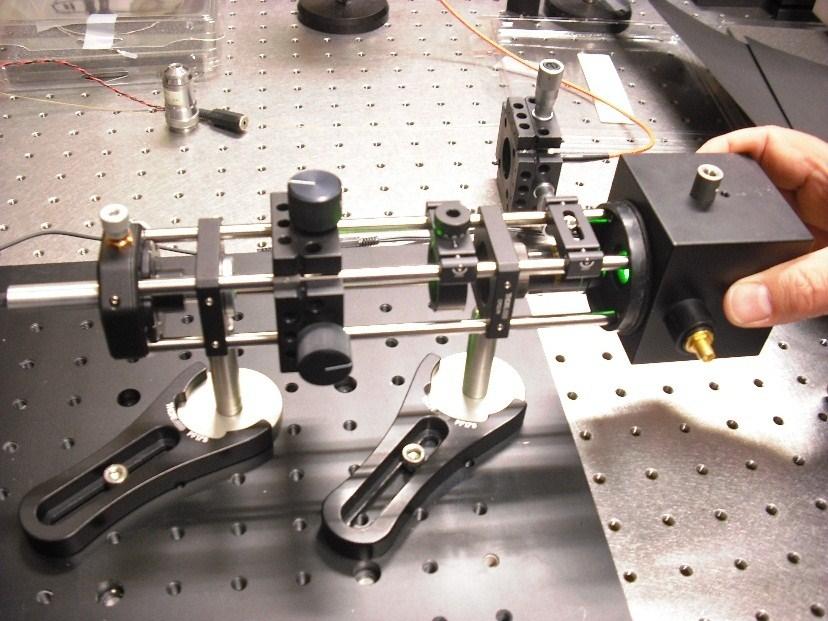
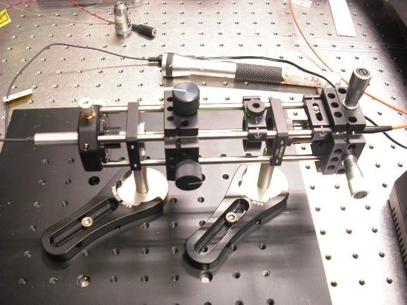
28 Measurement of the reference flux (100%) 0.5 mm pinhole Iris F/3 Laser 3 X objective 16 X objective Integrating sphere I / V transducer Photo diode 28
29 Measurement of the flux through fibre Laser 0.5 mm pinhole Iris F/3 Fibre 3 X objective 16 X objective Iris F/3 Integrating sphere I / V transducer 29 Photo diode
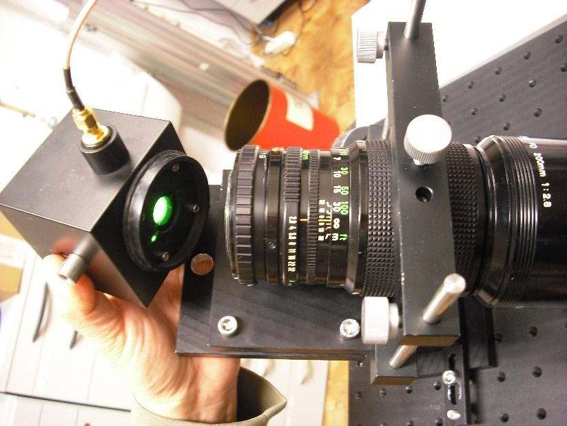
30 Integration sphere 30

31 Measurements CAOS 31 St. Niklausen Aspekt 2017
32 Measurements Injection in fibre F/3 Laser wavelength 532 nm Peak correction coefficient h= E i E o 100 (%) Fibre efficiency 82.4% Spectrograph only 39.7% 42.2% (*) Spectrograph + fibre 32.7% 34.8% (*) (*) After applying peak correction coefficient 32
33 Conclusions CAOS The efficiency of an instrument is a feature as important as any other (resolution, wavelength range, etc..) Most critical component: the fibre. A bad FDR could cause you loosing 30% of the light (imagine you need a telescope 30% bigger!). Efficiency measurements can be easily performed with lasers (blue, green and red). 33
Spectroscopic Instrumentation
 Spectroscopic Instrumentation Theodor Pribulla Astronomical Institute of the Slovak Academy of Sciences, Tatranská Lomnica, Slovakia Spectroscopic workshop, February 6-10, 2017, PřF MU, Brno Principal
DESIGN NOTE: DIFFRACTION EFFECTS
 NASA IRTF / UNIVERSITY OF HAWAII Document #: TMP-1.3.4.2-00-X.doc Template created on: 15 March 2009 Last Modified on: 5 April 2010 DESIGN NOTE: DIFFRACTION EFFECTS Original Author: John Rayner NASA Infrared
Supplementary Materials
 Supplementary Materials In the supplementary materials of this paper we discuss some practical consideration for alignment of optical components to help unexperienced users to achieve a high performance
Exam 4. Name: Class: Date: Multiple Choice Identify the choice that best completes the statement or answers the question.
 Name: Class: Date: Exam 4 Multiple Choice Identify the choice that best completes the statement or answers the question. 1. Mirages are a result of which physical phenomena a. interference c. reflection
Astro 500 A500/L-18 1
 Astro 500 A500/L-18 1 Lecture Outline Spectroscopy from a 3D Perspective ü Basics of spectroscopy and spectrographs ü Fundamental challenges of sampling the data cube Approaches and example of available
Southern African Large Telescope High-Resolution Spectrograph SALT HRS. 3210AE0005 Optical Design
 Southern African Large Telescope High-Resolution Spectrograph SALT HRS 3210AE0005 Optical Design Stuart Barnes P.L. Cottrell Michael D. Albrow Graeme Kershaw University of Canterbury Issue 2.7 17 March
UV/Optical/IR Astronomy Part 2: Spectroscopy
 UV/Optical/IR Astronomy Part 2: Spectroscopy Introduction We now turn to spectroscopy. Much of what you need to know about this is the same as for imaging I ll concentrate on the differences. Slicing the
Cascaded holographic spectrographs for astronomical applications
 Cascaded holographic spectrographs for astronomical applications advanced modelling and experimental proof Eduard Muslimov Postdoc, group RnD, LAM RnD seminars, September 28 th 2017 Outline of the talk
Exercise 8: Interference and diffraction
 Physics 223 Name: Exercise 8: Interference and diffraction 1. In a two-slit Young s interference experiment, the aperture (the mask with the two slits) to screen distance is 2.0 m, and a red light of wavelength
Southern African Large Telescope. Prime Focus Imaging Spectrograph. Instrument Acceptance Testing Plan
 Southern African Large Telescope Prime Focus Imaging Spectrograph Instrument Acceptance Testing Plan Eric B. Burgh University of Wisconsin Document Number: SALT-3160AP0003 Revision 2.2 29 April 2004 1
ABSTRACT 1. INTRODUCTION
 Design and testing of AR coatings for MEGARA optics R. Ortiz a, E. Carrasco a, G. Páez b, O. Pompa b, E. Sánchez-Blanco c, A. Gil de Paz d, J. Gallego d, J. Iglesias-Páramo e a Instituto Nacional de Astrofísica
Components of Optical Instruments. Chapter 7_III UV, Visible and IR Instruments
 Components of Optical Instruments Chapter 7_III UV, Visible and IR Instruments 1 Grating Monochromators Principle of operation: Diffraction Diffraction sources: grooves on a reflecting surface Fabrication:
3.0 Alignment Equipment and Diagnostic Tools:
 3.0 Alignment Equipment and Diagnostic Tools: Alignment equipment The alignment telescope and its use The laser autostigmatic cube (LACI) interferometer A pin -- and how to find the center of curvature
Observational Astronomy
 Observational Astronomy Instruments The telescope- instruments combination forms a tightly coupled system: Telescope = collecting photons and forming an image Instruments = registering and analyzing the
Optical Design. Instrument concept Foreoptics and slit viewer Spectrograph Alignment plan 3/29/13
 Optical Design Instrument concept Foreoptics and slit viewer Spectrograph Alignment plan 3/29/13 3/29/13 2 ishell Design Summary Resolving Power Slit width Slit length Silicon immersion gratings XD gratings
GEOMETRICAL OPTICS AND OPTICAL DESIGN
 GEOMETRICAL OPTICS AND OPTICAL DESIGN Pantazis Mouroulis Associate Professor Center for Imaging Science Rochester Institute of Technology John Macdonald Senior Lecturer Physics Department University of
Design Description Document
 UNIVERSITY OF ROCHESTER Design Description Document Flat Output Backlit Strobe Dare Bodington, Changchen Chen, Nick Cirucci Customer: Engineers: Advisor committee: Sydor Instruments Dare Bodington, Changchen
Lecture 4: Geometrical Optics 2. Optical Systems. Images and Pupils. Rays. Wavefronts. Aberrations. Outline
 Lecture 4: Geometrical Optics 2 Outline 1 Optical Systems 2 Images and Pupils 3 Rays 4 Wavefronts 5 Aberrations Christoph U. Keller, Leiden University, keller@strw.leidenuniv.nl Lecture 4: Geometrical
OPTICAL DESIGN OF A RED SENSITIVE SPECTROGRAPH
 OPTICAL DESIGN OF A RED SENSITIVE SPECTROGRAPH A Senior Scholars Thesis by EMILY CATHERINE MARTIN Submitted to Honors and Undergraduate Research Texas A&M University in partial fulfillment of the requirements
Better Imaging with a Schmidt-Czerny-Turner Spectrograph
 Better Imaging with a Schmidt-Czerny-Turner Spectrograph Abstract For years, images have been measured using Czerny-Turner (CT) design dispersive spectrographs. Optical aberrations inherent in the CT design
PHY 431 Homework Set #5 Due Nov. 20 at the start of class
 PHY 431 Homework Set #5 Due Nov. 0 at the start of class 1) Newton s rings (10%) The radius of curvature of the convex surface of a plano-convex lens is 30 cm. The lens is placed with its convex side down
arxiv: v1 [astro-ph.im] 30 Nov 2015
![arxiv: v1 [astro-ph.im] 30 Nov 2015](/thumbs/93/112317521.jpg "arxiv: v1 [astro-ph.im] 30 Nov 2015") Astron. Nachr. / AN 336, No. 1, 0 1 (2015) / DOI DOI Comparing modal noise and FRD of circular and non-circular crosssection fibres D. P. Sablowski, D. Plüschke, M. Weber, K. G. Strassmeier and A. Järvinen
Astron. Nachr. / AN 336, No. 1, 0 1 (2015) / DOI DOI Comparing modal noise and FRD of circular and non-circular crosssection fibres D. P. Sablowski, D. Plüschke, M. Weber, K. G. Strassmeier and A. Järvinen
Scaling relations for telescopes, spectrographs, and reimaging instruments
 Scaling relations for telescopes, spectrographs, and reimaging instruments Benjamin Weiner Steward Observatory University of Arizona bjw @ asarizonaedu 19 September 2008 1 Introduction To make modern astronomical
High Resolution Optical Spectroscopy in the ELT Era. Cynthia S. Froning University of Texas at Austin May 25, 2016
 High Resolution Optical Spectroscopy in the ELT Era Cynthia S. Froning University of Texas at Austin May 25, 2016 Background Feasibility studies in 2005-2006: UC Santa Cruz, U. Colorado Not selected as
SIFS... SOAR Integral Field Spectrograph
 SIFS... SOAR Integral Field Spectrograph (ex- SIFUS) Jacques Lépine 1, Beatriz Barbuy 1, Clemens Gneiding 2, Antônio César de Oliveira 2, Bruno Castilho 2, Antônio Kanaan 3, Militão Figueredo 1, Cesar
DIMENSIONAL MEASUREMENT OF MICRO LENS ARRAY WITH 3D PROFILOMETRY
 DIMENSIONAL MEASUREMENT OF MICRO LENS ARRAY WITH 3D PROFILOMETRY Prepared by Benjamin Mell 6 Morgan, Ste156, Irvine CA 92618 P: 949.461.9292 F: 949.461.9232 nanovea.com Today's standard for tomorrow's
Design and Construction of VUES: the Vilnius University Echelle Spectrograph
 Design and Construction of VUES: the Vilnius University Echelle Spectrograph Colby Jurgenson, Debra Fischer, Tyler McCracken, David Sawyer, Matt Giguere, Andrew Szymkowiak, Fernando Santoro, and Gary Muller
Lecture 2: Geometrical Optics. Geometrical Approximation. Lenses. Mirrors. Optical Systems. Images and Pupils. Aberrations.
 Lecture 2: Geometrical Optics Outline 1 Geometrical Approximation 2 Lenses 3 Mirrors 4 Optical Systems 5 Images and Pupils 6 Aberrations Christoph U. Keller, Leiden Observatory, keller@strw.leidenuniv.nl
Image Slicer for the Subaru Telescope High Dispersion Spectrograph
 PASJ: Publ. Astron. Soc. Japan 64, 77, 2012 August 25 c 2012. Astronomical Society of Japan. Image Slicer for the Subaru Telescope High Dispersion Spectrograph Akito TAJITSU Subaru Telescope, National
Astr 535 Class Notes Fall
 Astr 535 Class Notes Fall 2017 86 4. Observing logs: summary program informtion, weather information, calibration data, seeing information, exposure information. COMMENTS are critical. READABILITY is critical
Will contain image distance after raytrace Will contain image height after raytrace
 Name: LASR 51 Final Exam May 29, 2002 Answer all questions. Module numbers are for guidance, some material is from class handouts. Exam ends at 8:20 pm. Ynu Raytracing The first questions refer to the
Focal Ratio Degradation study of non-circular shaped fibres
 Focal Ratio Degradation study of non-circular shaped fibres T. Feger (1), M. Goodwin (2), C. L. Poppett (3) (1) Karlsruhe School of Optics and Photonics, Schlossplatz 19, 76131 Karlsruhe, Germany (2) Australian
Chapter 3. Introduction to Zemax. 3.1 Introduction. 3.2 Zemax
 Chapter 3 Introduction to Zemax 3.1 Introduction Ray tracing is practical only for paraxial analysis. Computing aberrations and diffraction effects are time consuming. Optical Designers need some popular
EUV Plasma Source with IR Power Recycling
 1 EUV Plasma Source with IR Power Recycling Kenneth C. Johnson kjinnovation@earthlink.net 1/6/2016 (first revision) Abstract Laser power requirements for an EUV laser-produced plasma source can be reduced
Lecture 2: Geometrical Optics. Geometrical Approximation. Lenses. Mirrors. Optical Systems. Images and Pupils. Aberrations.
 Lecture 2: Geometrical Optics Outline 1 Geometrical Approximation 2 Lenses 3 Mirrors 4 Optical Systems 5 Images and Pupils 6 Aberrations Christoph U. Keller, Leiden Observatory, keller@strw.leidenuniv.nl
arxiv: v1 [astro-ph.im] 26 Mar 2012
![arxiv: v1 [astro-ph.im] 26 Mar 2012](/thumbs/72/66395735.jpg "arxiv: v1 [astro-ph.im] 26 Mar 2012") The image slicer for the Subaru Telescope High Dispersion Spectrograph arxiv:1203.5568v1 [astro-ph.im] 26 Mar 2012 Akito Tajitsu The Subaru Telescope, National Astronomical Observatory of Japan, 650 North
The image slicer for the Subaru Telescope High Dispersion Spectrograph arxiv:1203.5568v1 [astro-ph.im] 26 Mar 2012 Akito Tajitsu The Subaru Telescope, National Astronomical Observatory of Japan, 650 North
Southern African Large Telescope. RSS Throughput Test Plan
 Southern African Large Telescope RSS Throughput Test Plan Kenneth Nordsieck University of Wisconsin Document Number: SALT-3160AP0005 Revision 1.0 27 June, 2006 Change History Rev Date Description 1.0 27
Optical Design of the SuMIRe PFS Spectrograph
 Optical Design of the SuMIRe PFS Spectrograph Sandrine Pascal* a, Sébastien Vives a, Robert H. Barkhouser b, James E. Gunn c a Aix Marseille Université - CNRS, LAM (Laboratoire d'astrophysique de Marseille),
Fibre systems for cosmology
 Fibre systems for cosmology NE Approaching end of jet Nucleus Part of Disk SLIDE 1 Jeremy Allington-Smith and Graham Murray Centre for Advanced Instrumentation University of Durham Receding end of jet
GMT Instruments and AO. GMT Science Meeting - March
 GMT Instruments and AO GMT Science Meeting - March 2008 1 Instrument Status Scientific priorities have been defined Emphasis on: Wide-field survey science (cosmology) High resolution spectroscopy (abundances,
New opportunities of freeform gratings using diamond machining
 New opportunities of freeform gratings using diamond machining Dispersing elements for Astronomy: new trends and possibilities 11/10/17 Cyril Bourgenot Ariadna Calcines Ray Sharples Plan of the talk Introduction
SpectraPro 2150 Monochromators and Spectrographs
 SpectraPro 215 Monochromators and Spectrographs SpectraPro 215 15 mm imaging spectrographs and monochromators from are the industry standard for researchers who demand the highest quality data. Acton monochromators
Optical Components for Laser Applications. Günter Toesko - Laserseminar BLZ im Dezember
 Günter Toesko - Laserseminar BLZ im Dezember 2009 1 Aberrations An optical aberration is a distortion in the image formed by an optical system compared to the original. It can arise for a number of reasons
Method for the characterization of Fresnel lens flux transfer performance
 Method for the characterization of Fresnel lens flux transfer performance Juan Carlos Martínez Antón, Daniel Vázquez Moliní, Javier Muñoz de Luna, José Antonio Gómez Pedrero, Antonio Álvarez Fernández-Balbuena.
Stereoscopic Hologram
 Stereoscopic Hologram Joonku Hahn Kyungpook National University Outline: 1. Introduction - Basic structure of holographic display - Wigner distribution function 2. Design of Stereoscopic Hologram - Optical
Option G 4:Diffraction
 Name: Date: Option G 4:Diffraction 1. This question is about optical resolution. The two point sources shown in the diagram below (not to scale) emit light of the same frequency. The light is incident
Gemini 8m Telescopes Instrument Science Requirements. R. McGonegal Controls Group. January 27, 1996
 GEMINI 8-M Telescopes Project Gemini 8m Telescopes Instrument Science Requirements R. McGonegal Controls Group January 27, 1996 GEMINI PROJECT OFFICE 950 N. Cherry Ave. Tucson, Arizona 85719 Phone: (520)
The optical design of X-Shooter for the VLT
 The optical design of X-Shooter for the VLT P. Spanò *a,b, B. Delabre c, A. Norup Sørensen d, F. Rigal e, A. de Ugarte Postigo f, R. Mazzoleni c, G. Sacco b, P. Conconi a, V. De Caprio a, N. Michaelsen
Astro 500 A500/L-20 1
 Astro 500 1 Lecture Outline Spectroscopy from a 3D Perspective ü Basics of spectroscopy and spectrographs ü Fundamental challenges of sampling the data cube Approaches and example of available instruments
AgilOptics mirrors increase coupling efficiency into a 4 µm diameter fiber by 750%.
 Application Note AN004: Fiber Coupling Improvement Introduction AgilOptics mirrors increase coupling efficiency into a 4 µm diameter fiber by 750%. Industrial lasers used for cutting, welding, drilling,
Basic spectrometer types
 Spectroscopy Basic spectrometer types Differential-refraction-based, in which the variation of refractive index with wavelength of an optical material is used to separate the wavelengths, as in a prism
SpotOptics. The software people for optics OPAL O P A L
 Spotptics The software people for optics UTMTED WVEFRNT SENSR ccurate metrology of standard and aspherical lenses (single pass) ccurate metrology of spherical and flat mirrors (double pass) =0.3 to =50
Optical and mechanical parameters. 100 mm N. of elements 20.5 mm Dimensions 11.7 degrees Weight F/N = 4 (fixed) N.A.
 N.A.") OB SWIR 100 LENS OB-SWIR100/4 P/N C0416 General Description This family of high resolution SWIR lenses image from 0.9 2.3 µmm making them especially well-suited for PCB inspection, special laser applications,
OB SWIR 100 LENS OB-SWIR100/4 P/N C0416 General Description This family of high resolution SWIR lenses image from 0.9 2.3 µmm making them especially well-suited for PCB inspection, special laser applications,
Science 8 Unit 2 Pack:
 Science 8 Unit 2 Pack: Name Page 0 Section 4.1 : The Properties of Waves Pages By the end of section 4.1 you should be able to understand the following: Waves are disturbances that transmit energy from
Beam Shaping and Simultaneous Exposure by Diffractive Optical Element in Laser Plastic Welding
 Beam Shaping and Simultaneous Exposure by Diffractive Optical Element in Laser Plastic Welding AKL`12 9th May 2012 Dr. Daniel Vogler Page 1 Motivation: Quality and flexibility diffractive spot shaping
ADVANCED OPTICS LAB -ECEN Basic Skills Lab
 ADVANCED OPTICS LAB -ECEN 5606 Basic Skills Lab Dr. Steve Cundiff and Edward McKenna, 1/15/04 Revised KW 1/15/06, 1/8/10 Revised CC and RZ 01/17/14 The goal of this lab is to provide you with practice
Characteristics of point-focus Simultaneous Spatial and temporal Focusing (SSTF) as a two-photon excited fluorescence microscopy
 as a two-photon excited fluorescence microscopy") Characteristics of point-focus Simultaneous Spatial and temporal Focusing (SSTF) as a two-photon excited fluorescence microscopy Qiyuan Song (M2) and Aoi Nakamura (B4) Abstracts: We theoretically and experimentally
Characteristics of point-focus Simultaneous Spatial and temporal Focusing (SSTF) as a two-photon excited fluorescence microscopy Qiyuan Song (M2) and Aoi Nakamura (B4) Abstracts: We theoretically and experimentally
WIYN Bench Spectrograph Upgrade Report
 WIYN Bench Spectrograph Upgrade Report M. Bershady, Project Scientist This report was prepared on behalf of the Bench Upgrade Project Team who have all contributed to the content: George Jacoby (Project
LAMOST-HiRes. Fengshan - September 4, A Fiber-Fed High Resolution Echelle Spectrograph for LAMOST. Frank Grupp Slide 1
 LAMOST-HiRes Fengshan - September 4, 2006 LAMOST-HiRes A Fiber-Fed High Resolution Echelle Spectrograph for LAMOST frank@grupp-astro.de Frank Grupp Slide 1 Outline (1) Project general preconditions Scientific
Eric B. Burgh University of Wisconsin. 1. Scope
 Southern African Large Telescope Prime Focus Imaging Spectrograph Optical Integration and Testing Plan Document Number: SALT-3160BP0001 Revision 5.0 2007 July 3 Eric B. Burgh University of Wisconsin 1.
Image Formation. Light from distant things. Geometrical optics. Pinhole camera. Chapter 36
 Light from distant things Chapter 36 We learn about a distant thing from the light it generates or redirects. The lenses in our eyes create images of objects our brains can process. This chapter concerns
Figure 1. The Feros ber link (for details cf. text). the bers' entrance-surface diameter resulting in an eective f/4.6 feed which is well-suited to mi
. the bers' entrance-surface diameter resulting in an eective f/4.6 feed which is well-suited to mi") A two-beam two-slice image slicer for ber-linked spectrographs A. Kaufer Landessternwarte Heidelberg, Konigstuhl 12, D-69117 Heidelberg, Germany Abstract. For the Feros ber-linked high-resolution echelle
A two-beam two-slice image slicer for ber-linked spectrographs A. Kaufer Landessternwarte Heidelberg, Konigstuhl 12, D-69117 Heidelberg, Germany Abstract. For the Feros ber-linked high-resolution echelle
MEGARA Optical design: the new integral field unit and multi-object spectrograph for the GTC 10m telescope
 MEGARA Optical design: the new integral field unit and multi-object spectrograph for the GTC 10m telescope María-Luisa García-Vargas* a, Ernesto Sánchez-Blanco a, Esperanza Carrasco b, Armando Gil de Paz
A novel tunable diode laser using volume holographic gratings
 A novel tunable diode laser using volume holographic gratings Christophe Moser *, Lawrence Ho and Frank Havermeyer Ondax, Inc. 85 E. Duarte Road, Monrovia, CA 9116, USA ABSTRACT We have developed a self-aligned
KOSMOS. Optical Design
 KOSMOS Kitt Peak-Ohio State Multi-Object Spectrograph Optical Design Revision History Version Author Date Description 1.1 Ross Zhelem Initial Draft 1.2 Paul Martini July 20, 2010 Minor Edits, Disperser
7x P/N C1601. General Description
 METRICZOOM SWIR 7x METRIC ZOOM-SWIR ZOOM 7x P/N C1601 C General Description This family of high resolution METRIC ZOOM SWIR lenses image from 0.9 to 2.3 µm making them especially well-suited well for surveillance,
Spectroscopy of Ruby Fluorescence Physics Advanced Physics Lab - Summer 2018 Don Heiman, Northeastern University, 1/12/2018
 1 Spectroscopy of Ruby Fluorescence Physics 3600 - Advanced Physics Lab - Summer 2018 Don Heiman, Northeastern University, 1/12/2018 I. INTRODUCTION The laser was invented in May 1960 by Theodor Maiman.
instruments Solar Physics course lecture 3 May 4, 2010 Frans Snik BBL 415 (710)
") Solar Physics course lecture 3 May 4, 2010 Frans Snik BBL 415 (710) f.snik@astro.uu.nl www.astro.uu.nl/~snik info from photons spatial (x,y) temporal (t) spectral (λ) polarization ( ) usually photon starved
Solar Physics course lecture 3 May 4, 2010 Frans Snik BBL 415 (710) f.snik@astro.uu.nl www.astro.uu.nl/~snik info from photons spatial (x,y) temporal (t) spectral (λ) polarization ( ) usually photon starved
EE119 Introduction to Optical Engineering Spring 2002 Final Exam. Name:
 EE119 Introduction to Optical Engineering Spring 2002 Final Exam Name: SID: CLOSED BOOK. FOUR 8 1/2 X 11 SHEETS OF NOTES, AND SCIENTIFIC POCKET CALCULATOR PERMITTED. TIME ALLOTTED: 180 MINUTES Fundamental
PHYS 1020 LAB 7: LENSES AND OPTICS. Pre-Lab
 PHYS 1020 LAB 7: LENSES AND OPTICS Note: Print and complete the separate pre-lab assignment BEFORE the lab. Hand it in at the start of the lab. Pre-Lab Start by reading the entire prelab and lab write-up.
Optical System Design
 Phys 531 Lecture 12 14 October 2004 Optical System Design Last time: Surveyed examples of optical systems Today, discuss system design Lens design = course of its own (not taught by me!) Try to give some
 http://goldberg.lbl.gov 1 To EUV or not to EUV? That is the question. Do we need EUV interferometry and EUV optical testing? 17 Things you need to know about perfecting EUV optics. 2 The main things you
Gratings: so many variables
 Gratings: so many variables Scientific Reqts Give R s Slit limited resolution θ B Slit size on sky D tel Telescope Dia D pix Detector Pixel Size s pixels/slit width = sampling Variables to work with δ
Comparison of FRD (Focal Ratio Degradation) for Optical Fibres with Different Core Sizes By Neil Barrie
 for Optical Fibres with Different Core Sizes By Neil Barrie") Comparison of FRD (Focal Ratio Degradation) for Optical Fibres with Different Core Sizes By Neil Barrie Introduction The purpose of this experimental investigation was to determine whether there is a dependence
Comparison of FRD (Focal Ratio Degradation) for Optical Fibres with Different Core Sizes By Neil Barrie Introduction The purpose of this experimental investigation was to determine whether there is a dependence
Prac%ce Quiz 2. These are Q s from old quizzes. I do not guarantee that the Q s on this year s quiz will be the same, or even similar.
 Prac%ce Quiz 2 These are Q s from old quizzes. I do not guarantee that the Q s on this year s quiz will be the same, or even similar. A laser beam shines vertically upwards. What laser power is needed
EE119 Introduction to Optical Engineering Spring 2003 Final Exam. Name:
 EE119 Introduction to Optical Engineering Spring 2003 Final Exam Name: SID: CLOSED BOOK. THREE 8 1/2 X 11 SHEETS OF NOTES, AND SCIENTIFIC POCKET CALCULATOR PERMITTED. TIME ALLOTTED: 180 MINUTES Fundamental
Chapter 25 Optical Instruments
 Chapter 25 Optical Instruments Units of Chapter 25 Cameras, Film, and Digital The Human Eye; Corrective Lenses Magnifying Glass Telescopes Compound Microscope Aberrations of Lenses and Mirrors Limits of
Phys 2310 Mon. Oct. 16, 2017 Today s Topics. Finish Chapter 34: Geometric Optics Homework this Week
 Phys 2310 Mon. Oct. 16, 2017 Today s Topics Finish Chapter 34: Geometric Optics Homework this Week 1 Homework this Week (HW #10) Homework this week due Mon., Oct. 23: Chapter 34: #47, 57, 59, 60, 61, 62,
Slit. Spectral Dispersion
 Testing Method of Off-axis Parabolic Cylinder Mirror for FIMS K. S. Ryu a,j.edelstein b, J. B. Song c, Y. W. Lee c, J. S. Chae d, K. I. Seon e, I. S. Yuk e,e.korpela b, J. H. Seon a,u.w. Nam e, W. Han
LENS ZOOM-SWIR 7x P/N C0628
 ZOOM SWIR 7x LENS ZOOM-SWIR 7x P/N C0628 General Description This family of high resolution SWIR lenses image from 0.9 2.3 m making them especially well-suited for PCB inspection, special laser applications,
Why is There a Black Dot when Defocus = 1λ?
 Why is There a Black Dot when Defocus = 1λ? W = W 020 = a 020 ρ 2 When a 020 = 1λ Sag of the wavefront at full aperture (ρ = 1) = 1λ Sag of the wavefront at ρ = 0.707 = 0.5λ Area of the pupil from ρ =
MASSACHUSETTS INSTITUTE OF TECHNOLOGY Department of Electrical Engineering and Computer Science
 Student Name Date MASSACHUSETTS INSTITUTE OF TECHNOLOGY Department of Electrical Engineering and Computer Science 6.161 Modern Optics Project Laboratory Laboratory Exercise No. 3 Fall 2005 Diffraction
!!! DELIVERABLE!D60.2!
 www.solarnet-east.eu This project is supported by the European Commission s FP7 Capacities Programme for the period April 2013 - March 2017 under the Grant Agreement number 312495. DELIVERABLED60.2 Image
A New Solution for the Dispersive Element in Astronomical Spectrographs
 PUBLICATIONS OF THE ASTRONOMICAL SOCIETY OF THE PACIFIC, 122:201 206, 2010 February 2010. The Astronomical Society of the Pacific. All rights reserved. Printed in U.S.A. A New Solution for the Dispersive
Phys 531 Lecture 9 30 September 2004 Ray Optics II. + 1 s i. = 1 f
 Phys 531 Lecture 9 30 September 2004 Ray Optics II Last time, developed idea of ray optics approximation to wave theory Introduced paraxial approximation: rays with θ 1 Will continue to use Started disussing
Spectrophotometric calibration system for DECam
 Spectrophotometric calibration system for DECam J.-P. Rheault*, D. L. DePoy, T. W. Behm, E. W. Kylberg, Kris Cabral, Rick Allen, J. L. Marshall, Department of Physics and Astronomy, Texas A&M University,
CHARA AO Calibration Process
 CHARA AO Calibration Process Judit Sturmann CHARA AO Project Overview Phase I. Under way WFS on telescopes used as tip-tilt detector Phase II. Not yet funded WFS and large DM in place of M4 on telescopes
R.B.V.R.R. WOMEN S COLLEGE (AUTONOMOUS) Narayanaguda, Hyderabad.
 Narayanaguda, Hyderabad.") R.B.V.R.R. WOMEN S COLLEGE (AUTONOMOUS) Narayanaguda, Hyderabad. DEPARTMENT OF PHYSICS QUESTION BANK FOR SEMESTER III PAPER III OPTICS UNIT I: 1. MATRIX METHODS IN PARAXIAL OPTICS 2. ABERATIONS UNIT II
R.B.V.R.R. WOMEN S COLLEGE (AUTONOMOUS) Narayanaguda, Hyderabad. DEPARTMENT OF PHYSICS QUESTION BANK FOR SEMESTER III PAPER III OPTICS UNIT I: 1. MATRIX METHODS IN PARAXIAL OPTICS 2. ABERATIONS UNIT II
LEOK-3 Optics Experiment kit
 LEOK-3 Optics Experiment kit Physical optics, geometrical optics and fourier optics Covering 26 experiments Comprehensive documents Include experiment setups, principles and procedures Cost effective solution
Chapter 17: Wave Optics. What is Light? The Models of Light 1/11/13
 Chapter 17: Wave Optics Key Terms Wave model Ray model Diffraction Refraction Fringe spacing Diffraction grating Thin-film interference What is Light? Light is the chameleon of the physical world. Under
Photonics West Contact us for a Stock or Custom Quote Today! Edmund Optics BROCHURE
 Edmund Optics BROHURE Photonics West 2017 Product Highlights Beam Expanders Off-xis Parabolic Mirrors Right ngle Prisms ontact us for a Stock or ustom Quote Today! US: +1-856-547-3488 EUROPE: +44 (0) 1904
Lecture 3: Geometrical Optics 1. Spherical Waves. From Waves to Rays. Lenses. Chromatic Aberrations. Mirrors. Outline
 Lecture 3: Geometrical Optics 1 Outline 1 Spherical Waves 2 From Waves to Rays 3 Lenses 4 Chromatic Aberrations 5 Mirrors Christoph U. Keller, Leiden Observatory, keller@strw.leidenuniv.nl Lecture 3: Geometrical
SONG Stellar Observations Network Group. The prototype
 SONG Stellar Observations Network Group The prototype F. Grundahl1, J. Christensen Dalsgaard1, U. G. Jørgensen2, H. Kjeldsen1,S. Frandsen1 and P. Kjærgaard2 1) Danish AsteroSeismology Centre, University
Advances in Hyperspectral Imaging Technologies for Multi-channel Fiber Sensing
 Advances in Hyperspectral Imaging Technologies for Multi-channel Sensing Jay Zakrzewski*, Kevin Didona Headwall Photonics, Inc., 601 River Street, Fitchburg, MA, USA 01420 ABSTRACT A spectrograph s design,
WINERED: Optical design of warm infrared echelle spectrograph
 WINERED: Optical design of warm infrared echelle spectrograph Chikako Yasui a, Yuji Ikeda b, Naoto Kobayashi a, Sohei Kondo a, Atsushi Minami a, Kentaro Motohara a a Institute of Astronomy, University
Optics and Lasers. Matt Young. Including Fibers and Optical Waveguides
 Matt Young Optics and Lasers Including Fibers and Optical Waveguides Fourth Revised Edition With 188 Figures Springer-Verlag Berlin Heidelberg New York London Paris Tokyo Hong Kong Barcelona Budapest Contents
Refraction is the change in speed of a wave due to the wave entering a different medium. light travels at different speeds in different media
 Refraction Refraction is the change in speed of a wave due to the wave entering a different medium light travels at different speeds in different media this causes light to bend as it passes from one substance
Chapter 23. Light Geometric Optics
 Chapter 23. Light Geometric Optics There are 3 basic ways to gather light and focus it to make an image. Pinhole - Simple geometry Mirror - Reflection Lens - Refraction Pinhole Camera Image Formation (the
Chapter 36: diffraction
 Chapter 36: diffraction Fresnel and Fraunhofer diffraction Diffraction from a single slit Intensity in the single slit pattern Multiple slits The Diffraction grating X-ray diffraction Circular apertures
FRESNEL LENS TOPOGRAPHY WITH 3D METROLOGY
 FRESNEL LENS TOPOGRAPHY WITH 3D METROLOGY INTRO: Prepared by Benjamin Mell 6 Morgan, Ste156, Irvine CA 92618 P: 949.461.9292 F: 949.461.9232 nanovea.com Today's standard for tomorrow's materials. 2010