All About Custom Rear Screen Systems
|
|
|
- Myron Wilkerson
- 6 years ago
- Views:
Transcription


1 All About Custom Rear Screen Systems

2 The CinemaSource Home Theater Design Handbook. Copyright 2002 All rights reserved. Printed in the United States of America. No part of this book may be used or reproduced in any manner whatsoever without written permission, except in brief quotations embodied in critical reviews. CinemaSource is a registered federal trademark. For information contact: The CinemaSource Press, 18 Denbow Rd. Durham, NH 03824

3 All About Rear Screen Systems 3 REAR SCREEN SYSTEMS Custom-built rear screen systems are the big brothers of the 45" to 80" rear screen televisions commonly seen at A/V retailers. In fact, the internal construction is almost identical, just scaled up in size. Look inside one and you will find three basic elements: A large rear projection surface, a high- brightness projection display and a mirror (or two) to fold the light beam. Although they are expensive to build, custom-built rear screen systems appeal to many people because the mechanics of the display are hidden from view. The result is just a huge picture that appears to be hanging on the wall. The imaging sources behind most custom-built rear screen systems are three tube, front projection video monitors. These are used because the manufacturers of CRT projectors almost always build in circuitry that allows the picture scanning to be easily reversed for rear screen applications. In general, because the display applications are so similar, virtually all the features and requirements that apply to front projection applications also apply to rear screen applications. For example, if you want to display standard NTSC-rate 4:3 video images, you want a video-grade projector. If you have in mind line doubling, look for a data-grade projector, and if HDTV compatibility and 16:9 images are important, you want a graphics-grade projector. One feature, however, you do want, regardless of the grade of projector you chose is the capability of remote-controllable convergence. For those who are unfamiliar with convergence alignment, this is the procedure by which all three tubes in a display device are adjusted so the images they generate match each other across the screen surface. This procedure is often performed on older video projectors by manually adjusting a bank of analog waveform controls inside the projection unit itself. While this technique is still fine for front projectors, it is a real pain for rear projector applications because the units are often tucked into a small, closet-like


4 4 All About Rear Screen Systems enclosures with minimal accessibility. Projectors that allow remote convergence allow one to view the picture directly, usually by standing right in front of the display, and allow one to complete the alignment procedure with greatly increased precision. Once the province of CRTbased projectors exclusively, custom-built rear screens are starting to be constructed with LCD, DLP and other electronic imagingbased projectors. The main reason is brightness, these technologies offer total lumen outputs far in excess of CRT-based projectors. In case you are considering using an LCD or DLP projector in a rear screen system, there is an additional item to factor into the design process. The projector pixel structure and the surface structure of optical gain screens (lenticular/fresnel types) can interact causing "moire" patterns. These are swirling patterns that often occur when fine detailed structures overlay each other. The solution for those who want to use solid state imaging projectors in custom-built rear screens is to make sure that the screen manufacturer certifies the screen surface for electronic imaging use. Call the engineering staff at VUTEC for further information on this topic. Using Mirrors To Fold The Light Path After the image is generated by the projector, the next step is to project it on the back of a rear screen surface. Depending on the amount of room you have to build a rear screen enclosure, there are several design options. Some configurations simply aim the projector directly at the back of the rear projection screen surface. This is simple and works well enough, but because of the long throw distance of many video A Television Picture That Looks Like It s Hanging On The Wall projectors, can take up an awful lot of room. A far more common approach is to use one or two mirrors to "fold" the light path so the entire system can be fitted into a more narrow enclosure. As our diagrams on the following pages illustrate, the narrowest enclosures typically require two mirrors. Note: if you are beginning to get nervous about pulling out your old geometry text books just to design this contraption, don't sweat it. Vutec offers their RSS-1 and RSS-2 Retro- Trac systems preconstructed for custom rear screen systems. The way it works is that you let them know the physical parameters of the system (the size of the screen, the size of the enclosure it will be built into, the type of projector used, etc.) and they will design one of their Retro-Trac systems specifically for your application. They will even provide you with the plotted CAD diagrams to assist you with your design process. Did you think we skipped over the mirror part? Here too are several options to consider. First, standard rear surface "bathroom-type" mirrors are rarely used. This is because on common rear surface mirrors, light must pass through the front layer of glass first and then it is reflected off the rear surface. The problem is that during this process some light energy is scattered and lost. Far preferable are front-surface mirrors. The first type uses glass as a substrate with a polished aluminum surface applied to the front of the glass. The advantage is less light loss; when light strikes the front surface of the mirror it bounces directly off. Another second mirror technology uses metalcoated polyester film. Offered under the Mirror- Tec brand name by Vutec, these mirrors are highly reflective (minimum reflectivity is 94%) and have the added bonus of being extremely light. These glassless
5 All About Rear Screen Systems 5 Folding a projector light path with a single mirror Folding a projector light path with dual mirrors


6 6 All About Rear Screen Systems A 16:9 CUSTOM- BUILT REAR SCREEN SYSTEM Speakers mirrors are rapidly becoming the preferred solution for rear projection system designers due to the ease of installation and overall cost advantage when compared to front surface glass types. If there is any downside to aluminized plastic mirrors, it is that they are slightly more delicate than glass-based types so when it is time for cleaning and dusting, one just has to be a bit more careful. The Rear Screen Surface The key to building a high performance, custom-built rear screen system is choosing the best final element in the display system; the rear screen surface. There are two general types available: diffusion screen surfaces and lenticular/fresnel screen surfaces. Let's look at standard diffusion surfaces first. The original diffusion surfaces were "etched glass". These were sheets of optically clear glass that are simply rough sandblasted on one side. The way they work is that the sandblasted side, in effect, gets engraved with thousands of small irregular lenses that function to disperse light rays uniformly in a wide 180 degree viewing cone. Today, glass-based diffusion screens are still common but the diffusing surface is not sandblasted, instead it is created by spraying a special chemical coating directly on the glass. Interestingly, the advantage of this technique is that by applying different amounts of the coating material, a diffusion screen can actually be given a slight amount of gain. Retro-Vu, Vutec s diffusion rear screen material, for example, can be ordered in gains of 1.0 to 2.5. This allows the system designer a great deal of flexibility when designing the display. When planning the construction, if muscling a 10 foot piece of glass into a custom rear screen enclosure sounds scary, you may want to consider an acrylic diffusion screen. These plastic-based screens are much lighter and considered easier to install than their glassbased counterparts, however, like anything constructed of plastic, one has to be careful about scratches. People with children take note. Acrylic-based diffusion screens are also offered with different amounts of gain (also 1.0 to 2.5) via special optical coatings. Lenticular/fresnel screen surfaces operate in a more controlled way than diffuser surfaces. They produce video images using actual optical lens technology, albeit in a rather unfamiliar way. Instead of the familiar smaller convex and concave lenses, the ones you see on cameras and telescopes, screen manufacturers effectively fabricate entire sheets of plastic into giant lenses. Let s start with the first surface the light passes through: the fresnel surface. Fresnel surfaces are scored with hundreds of miniature circular slopes that function to "collimate" incident light rays so they exit the surface at right angles to the surface of the screen. The result of this collimation process to the observer is that the picture is more uniform in brightness, without dimmer edges that can often be seen on diffusion-type screens. After passing through the fresnel surface, the light then passes onto the lenticular surface. This surface is not one big lens, like the fresnel surface, but is actually hundreds of vertical cylindrical ones, arranged so that light is spread around horizontally. This is done to ensure a wide viewing cone so audience members can view a bright picture regardless of seating position. Another feature you find on lenticular screens is a series of vertical ribs that are painted black. These "unused" parts of the lenticular surface are designed to absorb incident light in the room and thus improve the contrast range of the picture. Lenticular screens with black stripes typically are more expensive than the simpler lenticular surfaces, but offer greater performance.


7 All About Rear Screen Systems 7 Draper s RPS Rear Screen Assembly System Vutec s RSS-1 and RSS-2 Retro-Trac Universal Rail Systems make rear screen system design easy
8 8 All About Rear Screen Systems The Physics Of Rear Screen Surfaces We can characterize reflected light in three general ways. As you may remember from high school physics class, light itself is a form of electromagnetic radiation that travels in perfectly straight lines from the emitter to the source (at least in home theater rooms, Astrophysicists please don t write us). If we look at a highly reflective source like the surface of a still pond or a glass mirror, incident light rays bounce off at the same angle they arrived at. Physicists refer to this as the law of specular reflection and our diagram on the right illustrates how this works. In short, the angle of incidence, the angle the light strikes the surface, equals the angle of reflection. As you may surmise, mirrors make pretty poor projection screens because of the tendency for light rays to bounce directly off the surface without regard to where the audience is. A good projection screen requires a surface that diffuses the incident light around a large horizontal angle so that all audience members can see the image. The best example of this phenomena is a "Labertian diffuse surface" and is the basis for the common matte-white front projection screen. However, diffuse labertian-type screens aren't perfect for all applications. They often are considered lacking brightness because a lot of light is "wasted" by throwing it around the room off-axis. A far better screen would be one that throws a majority of the light energy back to the viewing audience, and this is exactly the principle behind gain screens. (This topic is covered in more detail in the first chapter) commonly used but the diffusing surface is generally a special coating whose application can be carefully controlled to produce different amounts of gain. Another method to produce gain screens uses optical lens technology, albeit in a rather unfamiliar way. Instead of the familiar smaller convex and concave lens, the ones you see on cameras and telescopes, screen manufacturers effectively fabricate entire sheets of plastic into giant lenses. The favorite configuration presently used is a sandwich of a lenticular and a fresnel surface. Let's start with the surface closest to the projector; the fresnel surface. This lens surface is actually scored with hundreds of miniature slopes that function to bend incident light rays so they exit the surface at right angles to the surface of the screen. Our diagram on the next page illustrates this effect. To the observer, the result of this "collimation" process is that the picture is distinctly more uniform in brightness. Absent are the perceptually dimmer How Rear Screens Work Rear screen surfaces behave in a similar fashion to front screens, the only difference is that the technology used to create rear screen surfaces is transmissive, not reflective. First, let's look at a standard diffusion rear screen surface. In general, there are three primary types of materials that are used: etched glass, coated glass, and coated acrylic. The first type, etched glass, consisted of a sheet of glass that was sandblasted (etched) on the viewing side. This side of the screen, in effect, gets stamped with thousands of small irregular lenses that disperse light rays isotropically, that is, around a 180 degree angle. Today glass and acrylic rear screens are Three Ways To Characterize Reflected Light

9 All About Rear Screen Systems 9 edges that you see on diffusion-type screens. After passing through the fresnel surface, the light then passes onto the lenticular surface. This surface is not a big lens, like the fresnel surface, but is actually hundreds of vertical ones, arranged so that light is spread around the horizontal axis. This is done to ensure a wide viewing cone. Note that this wide viewing angle is typically designed in the horizontal axis not in the vertical. As you can see in the diagram below, the angular gain plot of a typical rear screen surface s vertical characteristics is very sharp. The rational here is that a wide viewing cone in the vertical dimension would waste light. Most everyone sits within a few degrees of each other vertically, so engineers design rear screen surfaces to project most of the image out in that direction. Another feature you find on lenticular screens is a series of small vertical ribs that are painted black. These "unused" parts of the lenticular surface are painted black so as to absorb any incident light in the room. In rooms filled with a modest amount of ambient light, from windows or other light sources, these screens display a much larger contrast range than ordinary rear screen surfaces. Lenticular screens with black stripes typically are more expensive than the simpler lenticular surfaces, but offer far greater performance in rooms with ambient light. How Rear Screen Surfaces Reflect Light How Lenticular and Fresnel Rear Screen Surfaces Work:
10 10 All About Rear Screen Systems Distribution Of Light F rom A Diffusion Rear Screen Distribution Of Light F rom A Coated Diffusion Rear Screen Distribution Of Light F rom A Lenticular/Fresnel Rear Screen
11 All About Rear Screen Systems 11
12 12 All About Rear Screen Systems REAR SCREEN INSTALLATION METHODS RSS-2 Dual Mirror Rear Screen System In order to assist you with your installation, Vutec s engineering department will provide at no extra charge a custom design layout based on the Retro-Trac rear screen projection system. The criteria that you need to supply includes: 1) The screen size and aspect ratio 2) The projector throw distance (generally included in the projector s installation manual) 3) The space available behind the screen 4) The sill height (height to the bottom of the screen). Once this information is given to Vutec, they will design a custom layout based on that criteria. It will show the mirror (s) sizes, dimensions of the Retro-Trac system and the position of the rear screen. For further details on Retro-Trac installation, call Vutec and request a copy of the RSS-1 or RSS-2 installation manuals (shown below). One the following three pages we illustrate the details involved with the physical installation of the HD and LD-series projection screen mounting systems. Both of these are designed for easy installation.


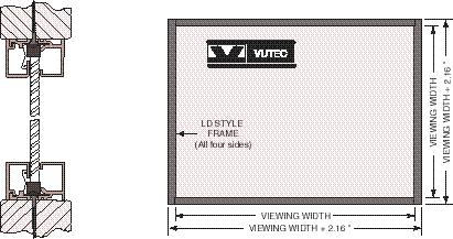
13 All About Rear Screen Systems 13 HD STYLE - REAR PROJECTION SCREEN FRAME LD STYLE - REAR PROJECTION SCREEN FRAME
14 14 All About Rear Screen Systems HD STYLE - REAR SCREEN FRAME INSTALLATION DETAILS
15 All About Rear Screen Systems 15 LD STYLE - REAR SCREEN FRAME INSTALLATION DETAILS
Test Review # 8. Physics R: Form TR8.17A. Primary colors of light
 Physics R: Form TR8.17A TEST 8 REVIEW Name Date Period Test Review # 8 Light and Color. Color comes from light, an electromagnetic wave that travels in straight lines in all directions from a light source
Image Formation. Light from distant things. Geometrical optics. Pinhole camera. Chapter 36
 Light from distant things Chapter 36 We learn about a distant thing from the light it generates or redirects. The lenses in our eyes create images of objects our brains can process. This chapter concerns
dnp Supernova Short Throw Screens
 dnp Supernova Short Throw Screens Up to You appreciate the cost-effectiveness of Ultra-Short-Throw projectors and the convenience they offer when installing AV systems in compact spaces. But what about
Complete the diagram to show what happens to the rays. ... (1) What word can be used to describe this type of lens? ... (1)
 What word can be used to describe this type of lens? ... (1)") Q1. (a) The diagram shows two parallel rays of light, a lens and its axis. Complete the diagram to show what happens to the rays. (2) Name the point where the rays come together. (iii) What word can be
Q1. (a) The diagram shows two parallel rays of light, a lens and its axis. Complete the diagram to show what happens to the rays. (2) Name the point where the rays come together. (iii) What word can be
Life Science Chapter 2 Study Guide
 Key concepts and definitions Waves and the Electromagnetic Spectrum Wave Energy Medium Mechanical waves Amplitude Wavelength Frequency Speed Properties of Waves (pages 40-41) Trough Crest Hertz Electromagnetic
NORTHERN ILLINOIS UNIVERSITY PHYSICS DEPARTMENT. Physics 211 E&M and Quantum Physics Spring Lab #8: Thin Lenses
 NORTHERN ILLINOIS UNIVERSITY PHYSICS DEPARTMENT Physics 211 E&M and Quantum Physics Spring 2018 Lab #8: Thin Lenses Lab Writeup Due: Mon/Wed/Thu/Fri, April 2/4/5/6, 2018 Background In the previous lab
Test Review # 9. Physics R: Form TR9.15A. Primary colors of light
 Physics R: Form TR9.15A TEST 9 REVIEW Name Date Period Test Review # 9 Light and Color. Color comes from light, an electromagnetic wave that travels in straight lines in all directions from a light source
UNIT 12 LIGHT and OPTICS
 UNIT 12 LIGHT and OPTICS What is light? Light is simply a name for a range of electromagnetic radiation that can be detected by the human eye. What characteristic does light have? Light is electromagnetic
LAB 12 Reflection and Refraction
 Cabrillo College Physics 10L Name LAB 12 Reflection and Refraction Read Hewitt Chapters 28 and 29 What to learn and explore Please read this! When light rays reflect off a mirror surface or refract through
10.2 Images Formed by Lenses SUMMARY. Refraction in Lenses. Section 10.1 Questions
 10.2 SUMMARY Refraction in Lenses Converging lenses bring parallel rays together after they are refracted. Diverging lenses cause parallel rays to move apart after they are refracted. Rays are refracted
Reading: Lenses and Mirrors; Applications Key concepts: Focal points and lengths; real images; virtual images; magnification; angular magnification.
 Reading: Lenses and Mirrors; Applications Key concepts: Focal points and lengths; real images; virtual images; magnification; angular magnification. 1.! Questions about objects and images. Can a virtual
Technical Notes. Introduction. Optical Properties. Issue 6 July Figure 1. Specular Reflection:
 Technical Notes This Technical Note introduces basic concepts in optical design for low power off-grid lighting products and suggests ways to improve optical efficiency. It is intended for manufacturers,
Lenses- Worksheet. (Use a ray box to answer questions 3 to 7)
") Lenses- Worksheet 1. Look at the lenses in front of you and try to distinguish the different types of lenses? Describe each type and record its characteristics. 2. Using the lenses in front of you, look
Lenses- Worksheet 1. Look at the lenses in front of you and try to distinguish the different types of lenses? Describe each type and record its characteristics. 2. Using the lenses in front of you, look
OPTICS DIVISION B. School/#: Names:
 OPTICS DIVISION B School/#: Names: Directions: Fill in your response for each question in the space provided. All questions are worth two points. Multiple Choice (2 points each question) 1. Which of the
Geometric Optics. Ray Model. assume light travels in straight line uses rays to understand and predict reflection & refraction
 Geometric Optics Ray Model assume light travels in straight line uses rays to understand and predict reflection & refraction General Physics 2 Geometric Optics 1 Reflection Law of reflection the angle
Instructional Resources/Materials: Light vocabulary cards printed (class set) Enough for each student (See card sort below)
 Enough for each student (See card sort below)") Grade Level/Course: Grade 7 Life Science Lesson/Unit Plan Name: Light Card Sort Rationale/Lesson Abstract: Light vocabulary building, students identify and share vocabulary meaning. Timeframe: 10 to 20
Grade Level/Course: Grade 7 Life Science Lesson/Unit Plan Name: Light Card Sort Rationale/Lesson Abstract: Light vocabulary building, students identify and share vocabulary meaning. Timeframe: 10 to 20
E X P E R I M E N T 12
 E X P E R I M E N T 12 Mirrors and Lenses Produced by the Physics Staff at Collin College Copyright Collin College Physics Department. All Rights Reserved. University Physics II, Exp 12: Mirrors and Lenses
Converging Lenses. Parallel rays are brought to a focus by a converging lens (one that is thicker in the center than it is at the edge).
.") Chapter 30: Lenses Types of Lenses Piece of glass or transparent material that bends parallel rays of light so they cross and form an image Two types: Converging Diverging Converging Lenses Parallel rays
Chapter 30: Lenses Types of Lenses Piece of glass or transparent material that bends parallel rays of light so they cross and form an image Two types: Converging Diverging Converging Lenses Parallel rays
Light and Applications of Optics
 UNIT 4 Light and Applications of Optics Topic 4.1: What is light and how is it produced? Topic 4.6: What are lenses and what are some of their applications? Topic 4.2 : How does light interact with objects
Physics for Kids. Science of Light. What is light made of?
 Physics for Kids Science of Light What is light made of? This is not an easy question. Light has no mass and is not really considered matter. So does it even exist? Of course it does! We couldn't live
Chapter 29/30. Wave Fronts and Rays. Refraction of Sound. Dispersion in a Prism. Index of Refraction. Refraction and Lenses
 Chapter 29/30 Refraction and Lenses Refraction Refraction the bending of waves as they pass from one medium into another. Caused by a change in the average speed of light. Analogy A car that drives off
This experiment is under development and thus we appreciate any and all comments as we design an interesting and achievable set of goals.
 Experiment 7 Geometrical Optics You will be introduced to ray optics and image formation in this experiment. We will use the optical rail, lenses, and the camera body to quantify image formation and magnification;
Light sources can be natural or artificial (man-made)
") Light The Sun is our major source of light Light sources can be natural or artificial (man-made) People and insects do not see the same type of light - people see visible light - insects see ultraviolet
Light The Sun is our major source of light Light sources can be natural or artificial (man-made) People and insects do not see the same type of light - people see visible light - insects see ultraviolet
Algebra Based Physics. Reflection. Slide 1 / 66 Slide 2 / 66. Slide 3 / 66. Slide 4 / 66. Slide 5 / 66. Slide 6 / 66.
 Slide 1 / 66 Slide 2 / 66 Algebra Based Physics Geometric Optics 2015-12-01 www.njctl.org Slide 3 / 66 Slide 4 / 66 Table of ontents lick on the topic to go to that section Reflection Refraction and Snell's
Basics of Light Microscopy and Metallography
 ENGR45: Introduction to Materials Spring 2012 Laboratory 8 Basics of Light Microscopy and Metallography In this exercise you will: gain familiarity with the proper use of a research-grade light microscope
INDEX OF REFRACTION index of refraction n = c/v material index of refraction n
 INDEX OF REFRACTION The index of refraction (n) of a material is the ratio of the speed of light in vacuuo (c) to the speed of light in the material (v). n = c/v Indices of refraction for any materials
Image Formation by Lenses
 Image Formation by Lenses Bởi: OpenStaxCollege Lenses are found in a huge array of optical instruments, ranging from a simple magnifying glass to the eye to a camera s zoom lens. In this section, we will
Cables and Interconnects
 Cables and Interconnects CinemaSource, 18 Denbow Rd., Durham, NH 03824 cinemasource.com 800-483-9778 CinemaSource Technical Bulletins. Copyright 2002 by CinemaSource, Inc. All rights reserved. Printed
machines 608 Trestle Point Sanford, FL Phone Fax
 Alignment for BOSSLASER machines 608 Trestle Point Sanford, FL 32771 Phone 888-652-1555 Fax 407-878-0880 www.bosslaser.com Table of Contents Four Corner Test. Error! Bookmark not defined. Vertical Alignment...
Ambient Light Rejecting WHITEBOARDSCREEN SERIES
 Ambient Light Rejecting WHITEBOARDSCREEN SERIES Section 1: Screen Design 1.1 What is it for? The versatile Ambient Light Rejecting WhiteBoardScreen has enhanced reflectivity: It is perfect for rooms with
LIGHT. ENERGY FOR LIFE 2 Presented by- Ms.Priya
 LIGHT ENERGY FOR LIFE 2 Presented by- Ms.Priya VOCABULARY 1. Opaque 2. Transparent 3. Translucent 4. Refraction 5. Reflection 6. Ray 7. Image 8. Virtual image 9. Medium 10.Vacuum 11. Lens 12. Spectrum
EUV Plasma Source with IR Power Recycling
 1 EUV Plasma Source with IR Power Recycling Kenneth C. Johnson kjinnovation@earthlink.net 1/6/2016 (first revision) Abstract Laser power requirements for an EUV laser-produced plasma source can be reduced
Table of Contents DSM II. Lenses and Mirrors (Grades 5 6) Place your order by calling us toll-free
 Place your order by calling us toll-free") DSM II Lenses and Mirrors (Grades 5 6) Table of Contents Actual page size: 8.5" x 11" Philosophy and Structure Overview 1 Overview Chart 2 Materials List 3 Schedule of Activities 4 Preparing for the Activities
DSM II Lenses and Mirrors (Grades 5 6) Table of Contents Actual page size: 8.5" x 11" Philosophy and Structure Overview 1 Overview Chart 2 Materials List 3 Schedule of Activities 4 Preparing for the Activities
Instructions. To run the slideshow:
 Instructions To run the slideshow: Click: view full screen mode, or press Ctrl +L. Left click advances one slide, right click returns to previous slide. To exit the slideshow press the Esc key. Optical
Applications of Optics
 Nicholas J. Giordano www.cengage.com/physics/giordano Chapter 26 Applications of Optics Marilyn Akins, PhD Broome Community College Applications of Optics Many devices are based on the principles of optics
Unit 8: Light and Optics
 Objectives Unit 8: Light and Optics Explain why we see colors as combinations of three primary colors. Explain the dispersion of light by a prism. Understand how lenses and mirrors work. Explain thermal
DLA-RS20 Full HD D-ILA Front Projector
 DLA-RS20 Full HD D-ILA Front Projector With the new DLA-RS20, the bigger the screen, the better the picture. Now every seat in your mini theater is the best in the house! The new DLA-RS20 brings THX certified
Chapter 23. Mirrors and Lenses
 Chapter 23 Mirrors and Lenses Notation for Mirrors and Lenses The object distance is the distance from the object to the mirror or lens Denoted by p The image distance is the distance from the image to
Mirrors, Lenses &Imaging Systems
 Mirrors, Lenses &Imaging Systems We describe the path of light as straight-line rays And light rays from a very distant point arrive parallel 145 Phys 24.1 Mirrors Standing away from a plane mirror shows
Howie's Laser Collimator Instructions:
 Howie's Laser Collimator Instructions: WARNING: AVOID DIRECT OR MIRROR REFLECTED EYE EXPOSURE TO LASER BEAM The laser collimator is a tool that enables precise adjustment of the alignment of telescope
Mastery. Chapter Content. What is light? CHAPTER 11 LESSON 1 C A
 Chapter Content Mastery What is light? LESSON 1 Directions: Use the letters on the diagram to identify the parts of the wave listed below. Write the correct letters on the line provided. 1. amplitude 2.
IMAGE SENSOR SOLUTIONS. KAC-96-1/5" Lens Kit. KODAK KAC-96-1/5" Lens Kit. for use with the KODAK CMOS Image Sensors. November 2004 Revision 2
 KODAK for use with the KODAK CMOS Image Sensors November 2004 Revision 2 1.1 Introduction Choosing the right lens is a critical aspect of designing an imaging system. Typically the trade off between image
PHYS 1020 LAB 7: LENSES AND OPTICS. Pre-Lab
 PHYS 1020 LAB 7: LENSES AND OPTICS Note: Print and complete the separate pre-lab assignment BEFORE the lab. Hand it in at the start of the lab. Pre-Lab Start by reading the entire prelab and lab write-up.
(50-155) Optical Box
 Optical Box") 614-0670 (50-155) Optical Box Your optical box should have the following items: 1 Optics Box 3 color filters (one of each): red, green, and blue. 1 curved mirror 1 right angle prism 1 equilateral prism
614-0670 (50-155) Optical Box Your optical box should have the following items: 1 Optics Box 3 color filters (one of each): red, green, and blue. 1 curved mirror 1 right angle prism 1 equilateral prism
Lenses. A transparent object used to change the path of light Examples: Human eye Eye glasses Camera Microscope Telescope
 SNC2D Lenses A transparent object used to change the path of light Examples: Human eye Eye glasses Camera Microscope Telescope Reading stones used by monks, nuns, and scholars ~1000 C.E. Lenses THERE ARE
 Efficiency of an Ideal Solar Cell (Henry, C. H. J. Appl. Phys. 51, 4494) No absorption radiative recombination loss Thermalization loss Efficiencies of multi-band-gap Solar Cell (Henry, C. H. J. Appl.
Spherical Mirrors. Concave Mirror, Notation. Spherical Aberration. Image Formed by a Concave Mirror. Image Formed by a Concave Mirror 4/11/2014
 Notation for Mirrors and Lenses Chapter 23 Mirrors and Lenses The object distance is the distance from the object to the mirror or lens Denoted by p The image distance is the distance from the image to
The Optics of Mirrors
 Use with Text Pages 558 563 The Optics of Mirrors Use the terms in the list below to fill in the blanks in the paragraphs about mirrors. reversed smooth eyes concave focal smaller reflect behind ray convex
L 32 Light and Optics [2] The rainbow. Why is it a rain BOW? Atmospheric scattering. Different colors are refracted (bent) by different amounts
![L 32 Light and Optics [2] The rainbow. Why is it a rain BOW? Atmospheric scattering. Different colors are refracted (bent) by different amounts](/thumbs/77/75013139.jpg "L 32 Light and Optics [2] The rainbow. Why is it a rain BOW? Atmospheric scattering. Different colors are refracted (bent) by different amounts") L 32 Light and Optics [2] Measurements of the speed of light The bending of light refraction Total internal reflection Dispersion Dispersion Rainbows Atmospheric scattering Blue sky and red sunsets Mirrors
L 32 Light and Optics [2] Measurements of the speed of light The bending of light refraction Total internal reflection Dispersion Dispersion Rainbows Atmospheric scattering Blue sky and red sunsets Mirrors
Chapter 3 Mirrors. The most common and familiar optical device
 Chapter 3 Mirrors The most common and familiar optical device Outline Plane mirrors Spherical mirrors Graphical image construction Two mirrors; The Cassegrain Telescope Plane mirrors Common household mirrors:
Physics 142 Lenses and Mirrors Page 1. Lenses and Mirrors. Now for the sequence of events, in no particular order. Dan Rather
 Physics 142 Lenses and Mirrors Page 1 Lenses and Mirrors Now or the sequence o events, in no particular order. Dan Rather Overview: making use o the laws o relection and reraction We will now study ormation
Sunlight Readability and Durability of Projected Capacitive Touch Displays for Outdoor Applications
 Sunlight Readability and Durability of By: Mike Harris, Product Manager, Ocular Touch, LLC Sunlight Readability Projected capacitive (PCAP) touch panels are rapidly replacing traditional mechanical methods
DIRECT PART MARKING THE NEXT GENERATION OF DIRECT PART MARKING (DPM)
") DIRECT PART MARKING THE NEXT GENERATION OF DIRECT PART MARKING (DPM) Direct Part Marking (DPM) is a process by which bar codes are permanently marked onto a variety of materials. The DPM process allows
DIRECT PART MARKING THE NEXT GENERATION OF DIRECT PART MARKING (DPM) Direct Part Marking (DPM) is a process by which bar codes are permanently marked onto a variety of materials. The DPM process allows
Chapter 23. Mirrors and Lenses
 Chapter 23 Mirrors and Lenses Mirrors and Lenses The development of mirrors and lenses aided the progress of science. It led to the microscopes and telescopes. Allowed the study of objects from microbes
CHAPTER 3LENSES. 1.1 Basics. Convex Lens. Concave Lens. 1 Introduction to convex and concave lenses. Shape: Shape: Symbol: Symbol:
 CHAPTER 3LENSES 1 Introduction to convex and concave lenses 1.1 Basics Convex Lens Shape: Concave Lens Shape: Symbol: Symbol: Effect to parallel rays: Effect to parallel rays: Explanation: Explanation:
CHAPTER 18 REFRACTION & LENSES
 Physics Approximate Timeline Students are expected to keep up with class work when absent. CHAPTER 18 REFRACTION & LENSES Day Plans for the day Assignments for the day 1 18.1 Refraction of Light o Snell
Mirrors and Lenses. Images can be formed by reflection from mirrors. Images can be formed by refraction through lenses.
 Mirrors and Lenses Images can be formed by reflection from mirrors. Images can be formed by refraction through lenses. Notation for Mirrors and Lenses The object distance is the distance from the object
Activity 6.1 Image Formation from Spherical Mirrors
 PHY385H1F Introductory Optics Practicals Day 6 Telescopes and Microscopes October 31, 2011 Group Number (number on Intro Optics Kit):. Facilitator Name:. Record-Keeper Name: Time-keeper:. Computer/Wiki-master:..
Chapter 36. Image Formation
 Chapter 36 Image Formation Real and Virtual Images Real images can be displayed on screens Virtual Images can not be displayed onto screens. Focal Length& Radius of Curvature When the object is very far
Section 23. Illumination Systems
 Section 23 Illumination Systems 23-1 Illumination Systems The illumination system provides the light for the optical system. Important considerations are the amount of light, its uniformity, and the angular
visual impact from any angle
 visual impact from any angle Vikuiti 1. Introduction For stunning images that are brilliantly sharp and clear the Vikuiti Rear Projection Display Screen gives high resolution and extreme contrast, brighter
Converging and Diverging Surfaces. Lenses. Converging Surface
 Lenses Sandy Skoglund 2 Converging and Diverging s AIR Converging If the surface is convex, it is a converging surface in the sense that the parallel rays bend toward each other after passing through the
Reflection and Refraction of Light
 Reflection and Refraction of Light Physics 102 28 March 2002 Lecture 6 28 Mar 2002 Physics 102 Lecture 6 1 Light waves and light rays Last time we showed: Time varying B fields E fields B fields to create
Chapter 23. Light Geometric Optics
 Chapter 23. Light Geometric Optics There are 3 basic ways to gather light and focus it to make an image. Pinhole - Simple geometry Mirror - Reflection Lens - Refraction Pinhole Camera Image Formation (the
Algebra Based Physics. Reflection. Slide 1 / 66 Slide 2 / 66. Slide 3 / 66. Slide 4 / 66. Slide 5 / 66. Slide 6 / 66.
 Slide 1 / 66 Slide 2 / 66 lgebra ased Physics Geometric Optics 2015-12-01 www.njctl.org Slide 3 / 66 Slide 4 / 66 Table of ontents lick on the topic to go to that section Reflection Refraction and Snell's
Intermediate 2 Waves & Optics Past Paper questions
 Intermediate 2 Waves & Optics Past Paper questions 2000-2010 2000 Q29. A converging lens has a focal length of 30 mm. (a) Calculate the power of this lens. (i) In the diagram below, which is drawn to scale,
Try to Recall GRADE VI LIGHT ENERGY. At the end of the module, you should be able to: Identify energy and its uses (light)
") GRADE VI LIGHT ENERGY At the end of the module, you should be able to: Identify energy and its uses (light) Try to Recall Study the pictures. Identify if the illustration shows mechanical or chemical energy.
GRADE VI LIGHT ENERGY At the end of the module, you should be able to: Identify energy and its uses (light) Try to Recall Study the pictures. Identify if the illustration shows mechanical or chemical energy.
ECEN 4606, UNDERGRADUATE OPTICS LAB
 ECEN 4606, UNDERGRADUATE OPTICS LAB Lab 2: Imaging 1 the Telescope Original Version: Prof. McLeod SUMMARY: In this lab you will become familiar with the use of one or more lenses to create images of distant
Repair System for Sixth and Seventh Generation LCD Color Filters
 NTN TECHNICAL REVIEW No.722004 New Product Repair System for Sixth and Seventh Generation LCD Color Filters Akihiro YAMANAKA Akira MATSUSHIMA NTN's color filter repair system fixes defects in color filters,
Optics looks at the properties and behaviour of light!
 Optics looks at the properties and behaviour of light! Chapter 4: Wave Model of Light Past Theories Pythagoras believed that light consisted of beams made up of tiny particles that carried information
PRINCIPLE PROCEDURE ACTIVITY. AIM To observe diffraction of light due to a thin slit.
 ACTIVITY 12 AIM To observe diffraction of light due to a thin slit. APPARATUS AND MATERIAL REQUIRED Two razor blades, one adhesive tape/cello-tape, source of light (electric bulb/ laser pencil), a piece
Sable Frame CineGrey 3D
 Sable Frame CineGrey 3D Ambient Light Rejecting Fixed Frame USER S GUIDE (spring type) Congratulations on your new Sable Frame purchase! The screen material included is our ISF Certified CineGrey 3D which
Condition Mirror Refractive Lens Concave Focal Length Positive Focal Length Negative. Image distance positive
 Comparison between mirror lenses and refractive lenses Condition Mirror Refractive Lens Concave Focal Length Positive Focal Length Negative Convex Focal Length Negative Focal Length Positive Image location
Optics Practice. Version #: 0. Name: Date: 07/01/2010
 Optics Practice Date: 07/01/2010 Version #: 0 Name: 1. Which of the following diagrams show a real image? a) b) c) d) e) i, ii, iii, and iv i and ii i and iv ii and iv ii, iii and iv 2. A real image is
Your Comments. That test was brutal, but this is the last physics course I have to take here WOOOOOO!!!!!
 Your Comments I'm kind o lost, this was a pretty heavy prelecture. I understand the equations and how we get them but I'm araid to say that I don't understand the concepts behind everything. Such as what
The grade 6 English science unit, Lenses, meets the academic content standards set in the Korean curriculum, which state students should:
 This area covers the phenomena created by lenses. A lens is a tool of daily use that can concentrate light by creating refraction or make things appear larger, sparking interest and curiosity in students.
Physics 1202: Lecture 19 Today s Agenda
 Physics 1202: Lecture 19 Today s Agenda Announcements: Team problems today Team 12: Kervell Baird, Matthew George, Derek Schultz Team 13: Paxton Stowik, Stacey Ann Burke Team 14: Gregory Desautels, Benjamin
Subtractive because upon reflection from a surface, some wavelengths are absorbed from the white light and subtracted from it.
 4/21 Chapter 27 Color Each wavelength in the visible part of the spectrum produces a different color. Additive color scheme RGB Red Green Blue Any color can be produced by adding the appropriate amounts
Physics 4L Spring 2010 Problem set 1 Due Tuesday 26 January in class
 Physics 4L Spring 2010 Problem set 1 Due Tuesday 26 January in class From Wolfson: Chapter 30 problem 36 (the flashlight beam comes out of the water some distance from the edge of the lake; the figure
Chapter 23. Mirrors and Lenses
 Chapter 23 Mirrors and Lenses Notation for Mirrors and Lenses The object distance is the distance from the object to the mirror or lens Denoted by p The image distance is the distance from the image to
Unit 2: Optics Part 2
 Unit 2: Optics Part 2 Refraction of Visible Light 1. Bent-stick effect: When light passes from one medium to another (for example, when a beam of light passes through air and into water, or vice versa),
Final Reg Optics Review SHORT ANSWER. Write the word or phrase that best completes each statement or answers the question.
 Final Reg Optics Review 1) How far are you from your image when you stand 0.75 m in front of a vertical plane mirror? 1) 2) A object is 12 cm in front of a concave mirror, and the image is 3.0 cm in front
Be aware that there is no universal notation for the various quantities.
 Fourier Optics v2.4 Ray tracing is limited in its ability to describe optics because it ignores the wave properties of light. Diffraction is needed to explain image spatial resolution and contrast and
KULLIYYAH OF ENGINEERING
 KULLIYYAH OF ENGINEERING DEPARTMENT OF ELECTRICAL & COMPUTER ENGINEERING ANTENNA AND WAVE PROPAGATION LABORATORY (ECE 4103) EXPERIMENT NO 3 RADIATION PATTERN AND GAIN CHARACTERISTICS OF THE DISH (PARABOLIC)
Ch 24. Geometric Optics
 text concept Ch 24. Geometric Optics Fig. 24 3 A point source of light P and its image P, in a plane mirror. Angle of incidence =angle of reflection. text. Fig. 24 4 The blue dashed line through object
APPLICATIONS FOR TELECENTRIC LIGHTING
 APPLICATIONS FOR TELECENTRIC LIGHTING Telecentric lenses used in combination with telecentric lighting provide the most accurate results for measurement of object shapes and geometries. They make attributes
CH. 23 Mirrors and Lenses HW# 6, 7, 9, 11, 13, 21, 25, 31, 33, 35
 CH. 23 Mirrors and Lenses HW# 6, 7, 9, 11, 13, 21, 25, 31, 33, 35 Mirrors Rays of light reflect off of mirrors, and where the reflected rays either intersect or appear to originate from, will be the location
ptical Short Course International
 ptical Short Course International 6679 N. Calle de Calipso, Tucson, AZ http://www.oscintl.com 520-797-9744 What s In The Box? Optics of Digital Projectors Weekly Newsletter Sponsored By: The Brand for
Name:.. KSU ID:. Date:././201..
 Name:.. KSU ID:. Date:././201.. Objective (1): Verification of law of reflection and determination of refractive index of Acrylic glass Required Equipment: (i) Optical bench, (ii) Glass lens, mounted,
PHYS:1200 LECTURE 31 LIGHT AND OPTICS (3)
") 1 PHYS:1200 LECTURE 31 LIGHT AND OPTICS (3) In lecture 30, we applied the law of reflection to understand how images are formed using plane and curved mirrors. In this lecture we will use the law of refraction
1 PHYS:1200 LECTURE 31 LIGHT AND OPTICS (3) In lecture 30, we applied the law of reflection to understand how images are formed using plane and curved mirrors. In this lecture we will use the law of refraction
Paper on: Optical Camouflage
 Paper on: Optical Camouflage PRESENTED BY: I. Harish teja V. Keerthi E.C.E E.C.E E-MAIL: Harish.teja123@gmail.com kkeerthi54@gmail.com 9533822365 9866042466 ABSTRACT: Optical Camouflage delivers a similar
Note on Posted Slides. Fermat s Principle of Least Time. History of Light. Law of Reflection The angle of reflection equals the angle of incidence.
 Note on Posted Slides These are the slides that I intended to show in class on Thu. Apr. 3, 2014. They contain important ideas and questions from your reading. Due to time constraints, I was probably not
Basic Optics System OS-8515C
 40 50 30 60 20 70 10 80 0 90 80 10 20 70 T 30 60 40 50 50 40 60 30 70 20 80 90 90 80 BASIC OPTICS RAY TABLE 10 0 10 70 20 60 50 40 30 Instruction Manual with Experiment Guide and Teachers Notes 012-09900B
Reflection! Reflection and Virtual Image!
 1/30/14 Reflection - wave hits non-absorptive surface surface of a smooth water pool - incident vs. reflected wave law of reflection - concept for all electromagnetic waves - wave theory: reflected back
ACRYLITE. for Lighting Technologies
 for Lighting Technologies A specialized material that is reliable and durable is one of the world s highest-quality and most versatile plastics. It can be manufactured with many different functional properties
LlIGHT REVIEW PART 2 DOWNLOAD, PRINT and submit for 100 points
 WRITE ON SCANTRON WITH NUMBER 2 PENCIL DO NOT WRITE ON THIS TEST LlIGHT REVIEW PART 2 DOWNLOAD, PRINT and submit for 100 points Multiple Choice Identify the choice that best completes the statement or
Physics 9 Wednesday, February 1, 2012
 Physics 9 Wednesday, February 1, 2012 learningcatalytics.com class session ID: 542970 Today: repeat soap bubble; measure λ for laser Today: telescope, human eye Friday: first of 3 days on fluids (liquids,
StarBright XLT Optical Coatings
 StarBright XLT Optical Coatings StarBright XLT is Celestron s revolutionary optical coating system that outperforms any other coating in the commercial telescope market. Our most popular Schmidt-Cassegrain
Physics Learning Guide Name:
 Physics Learning Guide Name: Instructions: Using a pencil, complete the following notes as you work through the related lessons. Show ALL work as is explained in the lessons. You are required to have this
Invisibility Cloak. (Application to IMAGE PROCESSING) DEPARTMENT OF ELECTRONICS AND COMMUNICATIONS ENGINEERING
 DEPARTMENT OF ELECTRONICS AND COMMUNICATIONS ENGINEERING") Invisibility Cloak (Application to IMAGE PROCESSING) DEPARTMENT OF ELECTRONICS AND COMMUNICATIONS ENGINEERING SUBMITTED BY K. SAI KEERTHI Y. SWETHA REDDY III B.TECH E.C.E III B.TECH E.C.E keerthi495@gmail.com
Invisibility Cloak (Application to IMAGE PROCESSING) DEPARTMENT OF ELECTRONICS AND COMMUNICATIONS ENGINEERING SUBMITTED BY K. SAI KEERTHI Y. SWETHA REDDY III B.TECH E.C.E III B.TECH E.C.E keerthi495@gmail.com