FocusMax V4 Tutorials
|
|
|
- Beverley Logan
- 5 years ago
- Views:
Transcription
1 Copyright <2014> by <Steve Brady>. All Rights Reserved.
2 Table of contents Tutorials... 3 Learning with Simulators... 4 MaxIm Star Pattern... 5 Simulated Stars with PinPoint... 9 ASCOM DSS Camera TheSkyX Using DSS (Deep Sky Survey) Nebulosity ASCOM DSS Camera AcquireStar AcquireStar Tab TheSkyX Image Link PinPoint Tab Plate Solve Tab FirstLight Wizard Running Vcurves Profile Window Image Calibration Near Focus HFD Setting / 67
3 Version /9/2015 Author: Steve Brady Contents Learning with Simulators FirstLight WIzard Running Vcurves Profile Window AcquireStar Near Focus HFD Setting Image Calibration 3 / 67
4 Learning with Simulators Running FocusMax With Simulators 4 / 67


5 MaxIm MaxIm 5 Star Pattern 5 Star Pattern MaxIm can be setup to generate a simulator 5 artificial star pattern which can be used to learn basic FocusMax functions 1. Open "Simulator 1" or "Simulator 2" system file on the main FocusMax System window by pressing 5 / 67
6 the small square button next to the System field 2. Open FocusMax Preferences (Menu / Open / Preferences) Select MaxIm DL under Camera control Set camera Number assignment, generally, Camera #1 is the main imaging camera and camera #2 is the second (guiding) camera Select Simulator Focuser's for both Systems Press colored Connect buttons to connect to the camera(s) and focuser(s). A blue line will appear if the hardware is connection was successfully established. There is no need to set the telescope simulator with this option. 6 / 67
7 3. Configure MaxIm camera simulator In MaxIm, set the Camera model = Simulator Noise = On Guide errors = Both FWHM = 5 Press advanced button Set the array size 768 x 511 Normalize ADU units to 0.1 sec (guider also) which will boost the intensity of each star in the 5 star pattern by a factor of 10 Pixel Width 10 & Height 10 Uncheck Color and Full frame operation Connect to the camera 7 / 67

8 4. Running FocusMax in Simulator Mode FocusMax should find the brightest star in the 5 'star' image when the Find button is pressed Run the FirstLight Wizard to generate a set of Vcurves Press the Focus button focus the system using simulator camera and focuser Press Select button to use the cursor to select a star to use for autofocus 8 / 67

9 Simulated Stars with PinPoint Using PinPoint to Generate Simulated Star Field You can generate a simulated star field with MaxIm if the Full Version of PinPoint is installed FocusMax must be setup to communicate with a simulator telescope 9 / 67

10 1. Select the "Simulator 1" or "Simulator 2".system file on the System window by pressing the small square button next to the System field 2. Configure MaxIm camera simulator In MaxIm, set the Camera model = Simulator Noise = On Guide errors = Both FWHM = 5 10 / 67
 Select MaxIm DL under Camera control Set camera Number assignment, generally, Camera #1 is the main imaging camera and camera #2 is the second")
11 Press advanced button Set the array size 768 x 511 Normalize ADU units to 0.1 sec (guider also) Pixel Width 10 & Height 10 Uncheck Color and Full frame operation Connect to the camera 3. Open FocusMax Preferences (Menu / Open / Preferences) Select MaxIm DL under Camera control Set camera Number assignment, generally, Camera #1 is the main imaging camera and camera #2 is the second (guiding) camera Select Simulator Focuser's for both Systems Select the simulator telescope connection such as TheSky Controlled Telescope and set the telescope to simulator in the planetarium software. Press colored Connect buttons to connect to your hardware. A blue line will appear if the hardware is connection was successfully established. A black line will appear if the telescope is tracking which is required for simulated stars to be generated. 11 / 67
12 4. Setup PinPoint Open the AcquireStar window and select PinPoint as the Plate Solve Method. Enable Simulate starfields 12 / 67

13 Select the PinPoint Tab and set the path to your catalog. The best best choice is the Guide Star Catalog. Press the Test PinPoint button to verify that you have a full PinPoint license Press the Test Catalog button to lookup stars in the selected star catalog. The results will be displayed in the Log 5. Running FocusMax in Simulator Mode Move the focuser to the mid-point of the focuser travel. This can be determined by opening Preferences / Setup then pressing the small (chooser) focuser button to open the driver then press the Properties button.the mid-point o the focuser travel will be 0.5*Maximum Position. (2500 in the screen example below). 13 / 67

14 Find and slew the simulator telescope to a star that is 6th mag or fainter - the star should be somewhat isolated from other nearby stars Star coordinates J2000: 02h 43m s ' " J2000 Topocentric: 02h 44m s ' " Press Find and FocusMax will proceed take an image, create a simulated star field, find the brightest star in the field and subframe the star. 14 / 67
15 Run the FirstLight Wizard to generate a set of Vcurves - note that the star diameter will increase as the focuser moves further away from the mid-point of the focus travel Press the Focus button focus the system using simulator camera and focuser Press Select button to use the cursor to select a star to use for autofocus Setup AcquireStar to automatically select a star for autofocus ASCOM DSS Camera Using ASCOM DSS Camera to Generate Simulated Star Field 15 / 67

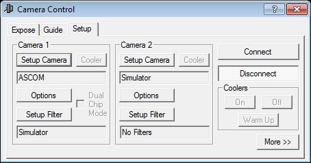
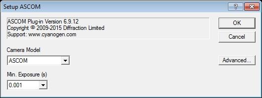
16 1. A Deep Sky Survey (DSS) ASCOM driver can be installed from This camera driver will download a DSS image from the internet and which may be used by FocusMax. Once installed: Press Setup Camera button Select the ASCOM camera Press Advanced button to select the telescope connection which will provide the RA & Dec coordinates. 16 / 67
17 17 / 67

18 2. If you are using AcquireStar then set the Min / Max magnitude for the current filter to 10 / 11 due to the deep images and overexposed stars in the field of view. 18 / 67

19 TheSkyX TheSkyX 19 / 67
20 Using DSS (Deep Sky Survey) Images From Deep Sky Survey TheSkyX is able to download and display Deep Sky Survey (DSS) images which can be plate solved with PinPoint or TheSkyX IMage Link. This requires a license for TheSkyX Camera Add-on. 20 / 67


21 1. Setting up DSS on TheSkyX Open TheSkyX and Menu / Tools / Digital Sky Survey / Setup Tab. Select Web unless you own a copy of the DSS disk 21 / 67
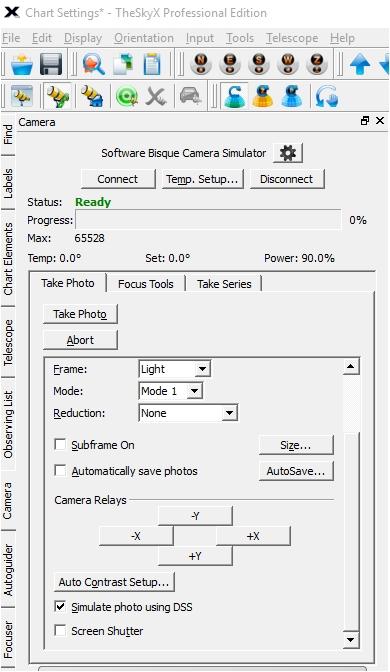
22 Setup the simulator camera in TheSkyX Enable Simulate photo using DSS and take a photo Open "Simulator 1" or "Simulator 2" file on the main FocsuMax System window by pressing the small square button next to the System field. 22 / 67
23 23 / 67
24 2. Plate solving images with TheSkyX Image Link: It is important to verify that you have the latest TheSkyX Image Link file is installed on your computer. Open TheSkyX / Menu / Tools / Image Link Click on All Sky tab to verify that you have the latest file installed (as shown below). If it is not up to date, then press the link to sign in to the Software Bisque site and download 1.7 gigabyte file. 24 / 67

25 Once installed you have the option to use 'Image Link All Sky for scripted operations IMage Link' - see above screen shot Enable 'Use Set the Image scale for your system or enable 'Blind' or 'Search a range of image scales' Open FocusMax / Preferences / AcquireStar and select TheSkyX method. 25 / 67
26 You may test the setup by clicking Plate Solve tab and pressing Expose and Solve to take an image and attempt to plate solve. 26 / 67

27 3. Plate solving images with PinPoint: Setup FocusMax to use TheSkyX camera control and AcquireStar plate solve method to TheSkyX. 27 / 67

28 Select PinPoint catalog and set the path to the folder containing the star catalog. Press the Test PinPoint button to verify that the Full version of PinPoint is installed. Press the Test Catalog button to verify that PinPoint can read successfully locate stars int the catalog. 28 / 67


29 On the Plate Solve Tab, set Binning and image plate scale to 1.7 arc-sec/pixel for the DSS images. Verify that the simulator Camera, Focuser and Telescope are connected Press the Expose and Solve button to take a simulated image and plate solve using PinPoint. 29 / 67
30 30 / 67

31 4. Using the DSS 31 / 67
32 Find and slew the simulator telescope to a star that is 11th mag or fainter - the star should be somewhat isolated from other nearby stars. You may need to adjust thetarget flux value or the Max Exposure time on the Autofocus window. Press Find to take an image - FocsuMax should identify the brightest star int he field then subframe the target star 32 / 67
33 Run the FirstLight Wizard generate a set of Vcurves. Once you have TheSkyX successfully taking simulator DSS images and PinPoint can solve the images, then continue to setup AcquireStar so that a star in the desired magnitude range can be located and used for autofocusing. Nebulosity 4 Nebulosity 4 33 / 67
34 ASCOM DSS Camera Using ASCOM DSS Camera to Generate Simulated Star Field 34 / 67
35 1. A Deep Sky Survey (DSS) ASCOM driver can be installed from This camera driver will download a DSS image from the internet and which may be used by FocusMax. Once installed: Press button to select the camera Select the ASCOM camera Press Advanced button to select the telescope connection which will provide the RA & Dec coordinates. 35 / 67


36 2. If you are using AcquireStar then set the Min / Max magnitude for the current filter to 10 / 11 due to the 36 / 67
37 deep images and overexposed stars in the field of view. 37 / 67
38 AcquireStar Setting up AcquireStar Astronomers are using AcquireStar with automated telescopes to perform a periodic focus update to assure that images acquired during the night are perfectly focused. AcquireStar can be operated manually by a push of a button or through automation within a script. 38 / 67
39 AcquireStar will identify and acquire a target star for autofocus that falls within the user defined requirements. This feature requires ThjeSkyX ImageLink or the full version of PinPoint. AcquireStar will not work with the current version of PinPoint LE bundled with MaxIm V3 or higher. At the push of a button or from a script, AcquireStar will (depending on user settings): take short exposure and plate solve current telescope position using PinPoint or TheSkyX Image Link. initiate a search in a star catalog to identify stars that meet the user defined magnitude range identified stars will be screened for min slew altitude, side of meridian to prevent telescope flip slew the telescope to the first target star in the list take a short exposure and plate solve current telescope position tweak telescope pointing to center target star initiate autofocus routine perform a return slew to original position take a short exposure and plate solve current telescope position tweak telescope pointing to met user defined allowable pointing error 39 / 67

40 AcquireStar Tab AcquireStar Setup Tab The AcquireStar Tab shows the exposure and desired magnitude range that will used for selecting a star from the stars catalog. The bottom portion of the window is used up the process that AcquirStar will use in selecting and slewing the telescope to the stars found in the star catalog. Target Star: Target star selection from the star catalog are specified for each filter. Brightest magnitude to be selected from the catalog Dimmest magnitude to be selected from the catalog Exposure to be used to plate solve current telescope position Click in the cell to change a value and press Return or leave the cell to save the changes. Min Slew Altitude The minimum telescope slew altitude allowed. Number of Stars The minimum number of stars will be selected from the star catalog that meet the user defined parameters, default = / 67
 Simulator system must be selected on the main FocusMax System window Camera must be selected and connected Telescope must be connected and tracking - telescope may be a real or setup as")
41 Simulate starfields A simulated starfield can be generated for testing and learning the many FocusMax features PinPoint or PinPoint/AllSkymust be selected as the plate solve method (requires PinPoint Full not LE) Simulator system must be selected on the main FocusMax System window Camera must be selected and connected Telescope must be connected and tracking - telescope may be a real or setup as Simulator Return slew Enable to set the telescope to perform a return slew after acquiring the target star and performing the autofocus routine. Blind slew Enable to allow the telescope to perform all slews blind without using astrometric plate solving to determine telescope position. Disable this option if your telescope ia able to slew and bring the target star close to the center of the CCD image. Goto Zenith AcquireStar will begin the target star selection process at the zenith and expand in 2x2 degree increments until a suitable stars are found. Meridian Cross AcquireStar will allow target star from being selected on the other side of the meridian. Enable this feature if you are using a mount that does not flip, such as an equatorial fork mount. Sync Allow the telescope to sync to current position following a successful astrometric plate solution of the 41 / 67
42 current telescope position. Spiral Search Allow PinPoint to search adjacent catalog positions in an attempt to plate solve the current telescope position. Max error The maximum telescope position error (arc-minutes) following a telescope slew that that the user will accept before AcquireStar will attempt to fine tune the telescope position by taking another image and plate solving, default = 1 arc-min. Example: Setting Max Error = arc-min (5 arc-sec) With the authors 16 f/4.5, 70 FL telescope (1.05 /pixel), Paramount ME and a fresh TPoint model, the final return slew position is within a few arc-seconds after one, sometimes two 2 pointing updates Attempts The number of plate solve attempts to achieve required telescope pointing, default = 3 Method PinPoint to plate solve the telescope pointing PinPoint/AllSky requires an internet connection to send information to Astrometry.net plate solving service. TheSKyX Image Link to plate solve the telescope pointing. The user may enable utilize All Sky Image Link in TheSkyX if the appropriate catalogs have been installed Notes Do not select a target star magnitude that will saturate the camera sensor for any given filter. The user can specify the number of stars (default = 3) to select from the star catalog before the telescope slew is initiated. If the autofocus run fails, then the second star in the list is used, followed by the 3rd, etc.. 42 / 67
43 TheSkyX Image Link Setting up TheSkyX Image Link Images taken with TheSkyX Camera Add-on, MaxIm, or Nebulosity 4 may be plate solved using TheSkyX Image Link method. 1. It is important to verify that you have the latest TheSkyX Image Link file is installed on your computer. Open TheSkyX / Menu / Tools / Image Link Click on All Sky tab to verify that you have the latest file installed (as shown below). If it is not up to date, then press the link to sign in to the Software Bisque site and download 1.7 gigabyte file. Once installed you have the option to use 'Image Link All Sky for scripted operations Image Link' - see above screen shot Enable 'Use Set the Image scale for your system or enable 'Blind' or 'Search a range of image scales' 2. Open FocusMax / Preferences / AcquireStar and select TheSkyX method. 43 / 67
44 3. You may test the setup by clicking Plate Solve tab and pressing Expose and Solve to take an image and attempt to plate solve. 44 / 67
45 PinPoint Tab Setting up PinPoint 1. Setting up PinPoint Star Detection Min size - minimum size in pixels for star detection (default = 2) Sigma above mean - minimum standard deviation of the signal (star) above the background noise for star detection Border - the number of pixels to ignore around the perimeter of the image when plate solving (default = 4) 45 / 67
46 Catalog 'Expansion' setting will read additional stars from the catalog to aid in plate solving (default 30%) 'Use stars from' will extract stars in the defined magnitude range from plate solving (default -2.0 to 20.0) 'Catalog' combo lists the current catalogs that are available to be used by PinPoint. Pressing the small information button will open a text file that lists information about some of the available star catalogs. In general, the GSC is an excellent chose for most users. The USNO is useful if faint stars are required Folder is the path to the chosen catalog Buttons 'Test PinPoint' is used to verify that the full version of PonPont has been installed on the PC. Unfortunately, PinPoint LE which ships with MaxIm does not provide plate solving capabilities. 'Test Catalog' will verify that AcquireStar can access, read and count the number of stars in a 1.0x1.0 degree field centered on RA 00:00:00, Dec 0:00:00 from the chosen star catalog. The results will be displayed in the Log 46 / 67


47 Plate Solve Tab Plate Solve Tab The Plate Solve tab is used to set the desired binning and the image scale of your system and test to verify that a plate solve can be successfully performed. Image Binning defines the camera binning that will be used for determining telescope pointing. It is recommended that you use 2+ to improve S/N and reduce image download time X/Y scale is the camera unbinned scale in arc-sec / pixel. Press the small button to open the Scale calculator 47 / 67
48 Max Solve Time Set the maximum time in seconds to plate solve an image,default = 60 sec (PinPoint only). Buttons: 'Edit Star Avoid' will open a text file that contain a list of stars that will be ignored by AcquireStar. Occasionally AquireStar may locate a star in the star catalog that appears to FocusMax as double star which will result in poor or failed autofocus run. The file contains Star ID, Ra and Dec and magnitude delimited by ' ' 'ID RA Dec Mag ==> Any line starting with ' will be ignored. Do not delete this line 'GSC :52: :51: ==> sample - you may delete this line SAO :25:26 +42:36: Simply add the known problem star to the list and AcquireStar will ignore it. 'Expose & Solve' will take an image and attempt to plate solve the current telescope position using the plate solve method selected on the AcquireStar Setup tab. 48 / 67

 so that the focus position is mid-way in the in and out travel of the focuser.")

49 FirstLight Wizard FirstLight Wizard The First Light Wizard is designed to assist the new user in setting up the parameters for running a Vcurve for the first time. Once the Vcurve has been created and the data is saved then FocusMax is will able to autofocus your telescope. Running the First Light Wizard: 1. Manually focus the telescope the focus does not have to be exact, just close. 2. It is best if you can adjust the draw tube or move the primary mirror (SCT) so that the focus position is mid-way in the in and out travel of the focuser. This is important as FocusMax will require sufficient travel range inside and outside of focus in order to develop the full Vcurve. 3. Select a star near the zenith, press the Find button and verify in the Log that the resulting min/max flux falls within the boundary on the Setup tab and verify that the star is not saturated. 4. Select the First Light Wizard from the Wizard menu. 5. The wizard will prompt you at each step of the process. 6. The First Light Wizard will start by moving the focuser in small then larger increments away from the focus point as it attempts to estimate the slope of one side f the Vcurveʼ. The wizard will continue to 49 / 67

 or")

50 move the focuser until it achieves the HFD setting (default = 40). If your focuser cannot reach this HFD setting then Stop and re-run the First Light Wizard and reduce the HFD value to a smaller value when prompted. This is not uncommon if the focuser is not centered in the travel range of the focuser (as per step 2 above) or the focuser has limited travel. 7. Now that the First Light Wizard has estimated the Vcurve slope, it will proceed to take a series of subframe images from outside of focus, through focus to the other side of focus. 8. Open the Log if closed and watch the HFD change as the focuser is moved, an image taken and measured by FocusMax. 50 / 67
51 9. The slope of the lines for both left and right Vcurve lines and the Position Intercept Difference (PID) will be calculated and saved in your system Profile that is active. 51 / 67

52 10. FocusMax will then use the results to perform an autofocus run 52 / 67

.")
53 11. You have the option to rerun the Vcurve or exit. It is suggested that you collect multiple Vcurves 12. Pressing the Focus button on the Focus Tab which should result in a perfectly focused star Notes: Set the Target Star and Focus binning to 2 if you are using a DSLR camera. Verify that the focus position is approximately centered in the focuser travel range (step 2). This is particularly important if the focuser has limited travel and may not be able to move the focuser to achieve the max HFD value. 53 / 67
54 If the FistLight Wizard fails because it cannot achieve the max HFD setting (40 HFD in step 6), then reduce the max HFD value to the largest found in the Log. For example: If the default HFD setting =40 BUT the largest HFD found in Step 6 is 35 then adjust then set HFD = 35 in the text box. 54 / 67
55 Running Vcurves Running Vcurves Some users find that the First Light Wizard is not able to characterize their system or have a working undertanding of the Vcurve generation process and prefer to save time by running manual Vcurves. 1. Focus the telescope manually Adjust the focuser so that the focus position is approximately mid-way in the full range of travel on your focuser. Example - an Optec TCF-S focuser has a total range of 7,000 steps so the focus position should be adjusted to roughly 3,500 steps by adjusting the draw tube, primary mirror (SCT), etc. Verify that the focus position is approximately mid-way in the focus travel range (3,500 for the above example). Select a 4th-5th-6th mag star (fainter for larger apertures) near the zenith and center on CCD. Using your imaging program, set the exposure time to a 'recommended' value of 0.5 sec and take an image. Measure the star intensity and adjust the exposure or use a brighter/fainter star until the target star intensity is mid-way in the camera's ADU range. Open the Vcurve window, the current focuser position will be entered in the Centerʼ box. 2. Vcurve Parameter Settings: Half Width is the movement in steps away from the Center in both directions End Points are the Initial and Final focuser positions. 55 / 67
56 Step Increment sets the number of steps the focuser will move at one time Steps is the resulting number of moves that will be made when generating the Vcurve. Note that as you make adjustments in the boxes that the parameters will change once you leave the entry box or press Enter. Enable Autofocus If you want to perform an autofocus run after the Vcurve is completed. Repeat setting will rerun the Vcurve using the same settings above Images/position setting will take multiple images and average the HFD measurements at each focuser position. This feature is useful for reducing noise and will yield a more consistent Vcurve. Downside is it takes more time and if the temperature is dripping rapidly then it may negatively impact the overall accuracy of the Vcurve. A setting of 3 under stable conditions is recommended for many users. 3. Method #1 - Determining Half Width Press the Jog button and move the focuser In or Out 100 units then press the Find button Continue to move the focuser until you achieve an HFD of 20+ (30-40 is better) Note the focuser position Bring the focuser back to the focus position and press the Half Width button on the Vcurve window Enter the difference between the focus position and the position achieved when you manually jogged the focuser Example: Focuser position is 3,500 and 4,000 was the position to achieve 30 HFD. Enter the difference of 500 into the Half Width box Adjust the Step Increment value until you see Steps displayed Adjust the Step Increment until the Steps has an 'odd' number which helps sharpen the 'V' because each side of the 'V' Plot will have an even number of points. 4. Method #2 - Determining End Points Press the End Points button on the Vcurve window Press the Jog button and move the focuser 100 units 'Out' then press the Find button Continue to move the focuser until you achieve an HFD of 20+ (30-40 is better) Enter the focuser position in the Initial position Move the focuser In 200 units 'In' then press the Find button Continue to move the focuser until you find the position approximately equal to the HFD value above Enter the focuser position in the Final position Bring the focuser back to the focus position Example: Focus position is 3,500 'Out' position = 4,000 to achieve 30 HFD 'In' position = 3,000 to achieve 30 HFD Adjust the Step Increment value until you see 'Steps' displayed 5. Press the Run button and 'enjoy the show' as FocusMax characterizes your system by creating a Vcurve 6. Watch the 'V' plot while running a V-Curve cycle. As the points on the 'V' near the bottom watch the FMx Log's HFD value for each point on the 'V When the HFD reaches its lowest value and starts increasing note the lowest HFD's focuser Position. That position will be the (approximate) point of best focus. 7. Upon completion of the V-Curve cycle change the "Center" field before running another V-Curve cycle. {the 'Initial' and 'Final' fields should automatically adjust} This also helps center the apex of the 'V' on the center line of the V-Curve plot. 8. If the lowest HFD in the Log continually changes or the apex of the 'V' in the V-Curve plot drifts this can indicate: 56 / 67
57 The telescope has not reached thermal equilibrium with ambient temperature - wait until the telescope cools closer to air temperature. Temperature changed causing the focus point to drift - wait until temperature and telescope stabilize. Continual drift of lowest HFD in the V-Curve Log, or centering of the 'V' on the V-Curve plot can also indicate the focuser might be slipping. Notes: The extremes of the Vcurve should be on the order of HFD. The primary reason for the large HFD values is to improve the ability for FocusMax to determine the slope of the line. The larger transition from max to min (focus position) the better. This may be a challenge for some telescopes with short range of travel and/or telescopes with low focal rations which yield a shallow Vcurve. See Profile Window 57 / 67
58 Profile Window Profile window This window contains the results of the Vcurve runs that characterize your system. These parameters are the heart of the FocusMax algorithm and are unique for each system configuration. If you change a camera, focuser, add a device such as filter wheel or rotator, then a new PRofile should be created with a unique name so that the system parameters may be saved and loaded when you wish to focus the telescope. 1. Vcurve data is stored in the system ini file and can be viewed by opening the Profile window. The system name Average Left and Right slopes Average Position Intercept Difference (PID) Standard deviation Total number of points are used to calculate the mean values. 2. Data grid: Use column will allow you to select or unselect Vcurve data to be used for calculating the averages Date and time of the Vcurve run Position Intercept Difference (PID) Left and Right Slopes 58 / 67
 can be loaded into the Vcurve window and reviewed or shared with other users 3.")

59 Calculated Left and Right Steps per HFD (1/slope) Comments with camera binning, Total points used to generate the Vcurve and the number of good points used to estimate the slope of the line File name of the Vcurve run. Vcurve files (ending in.vcl) can be loaded into the Vcurve window and reviewed or shared with other users 3. Graph: Graphs of the Vcurve runs can be displayed based on Left or Right Slope, Left or Right Steps/HFD or PID The Sigma Limits setting in the Profile Window will allow you to identify Vcurve data that is errant or suspect. Note in the picture below that reading number 4 is at or slightly beyond the dashed Sigma Limit lines and can be considered a suspect data point. This can easily be excluded form the analysis by double clicking the 'Y' on data point #4 in the data grid which will toggle the 'Y' to 'N'' and automatically update the graph. 4. Delete Button: To delete Vcurve data Click the far left row number which will highlight the row(s) to delete then press the Delete button. 59 / 67

60 5. Review the data and look for any significant difference in the R and L Slopes, PI Difference. Entries that looks suspect can be excluded by clicking the Yʼ in the Use column. If the Comments column show many points that were excluded then you may want to consider removing the row You can permanently delete entries by clicking in the small box to the left of the Use column which will turn red then press the Delete Entries button. 60 / 67

61 Image Calibration Image Calibration This feature is requested by users that may have CCD defects such as hot pixels which FocusMax may attempt to use utilize for focusing. Enable image calibration which is found on the Features tab and follow this procedure: MaxIm image calibration 1. Create a set of dark & bias frames at the binning used for the initial image and autofocus sub-frame images (see Target Star Bin and Focus Bin in Preferences/Autofocus). 2. The Dark frame exposures should span the range which FocusMax may use (0.1, 1, 5, 10 sec...). You may want to create a set of calibration frames from 1x1 through 4x4 just in case you decide to change bin size. 3. Save the calibration frames to a directory 4. Load the saved images into MaxIm using menu/process/set Calibration MaxIm will extract the appropriate image and position in the calibration image to calibrate the FocusMax frames for the initial target star section and autofocus sub-frame images. 61 / 67

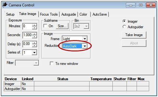
62 TheSkyX Camera Addon / CCDSoft image calibration Image Reduction will use 'AutoDark' with each light frame is taken. TheSkyX 62 / 67

63 CCDSoft 63 / 67
 Generate a Vcurve Examine the Vcurve graph and identify the circle which begins to deviate from a straight line.")
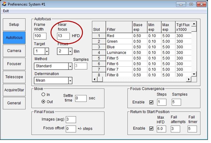
64 Near Focus HFD Setting Near Focus HFD Setting 1. To determine the best setting for Near Focus HFD (see Preferences / Setup ) Generate a Vcurve Examine the Vcurve graph and identify the circle which begins to deviate from a straight line. Determine the position in the Log by counting up the number of circles from the minimum HFD value (9.7 HFD below). Round up the HFD value in the Log (9.7 becomes 10) Add 2-3 HFD units to assure that the Near Focus Position is on the linear portion of the 'V' (13 in the example below). 64 / 67

65 2. Enter the value (13 HFD ) in the Near Focus HFD box 65 / 67
66 66 / 67
67 67 / 67
262 The Astrophotography Manual. Templates
 262 The Astrophotography Manual Templates I really didn t foresee the Internet. But then, neither did the computer industry. Not that that tells us very much of course the computer industry didn t even
What is CCD Commander?
 Matt Thomas What is CCD Commander? Multi-target imaging automation tool Controls all aspects of the imaging system Camera (Imaging and Guiding); Mount (Fork or GEM) Dome/Roll-of-roof; Focuser; Rotator;
We recommend downloading the latest core installer for our software from our website. This can be found at:
 Dusk Getting Started Installing the Software We recommend downloading the latest core installer for our software from our website. This can be found at: https://www.atik-cameras.com/downloads/ Locate and
CCD Commander. Automation of CCD Imaging. ...a User s Perspective. by Mike Sherick
 CCD Commander Automation of CCD Imaging...a User s Perspective by Mike Sherick 1 Presentation Overview: - Imaging Experience & Equipment Used - Projects and Current Setup - Remote Robotic Observatories
Scientific Image Processing System Photometry tool
 Scientific Image Processing System Photometry tool Pavel Cagas http://www.tcmt.org/ What is SIPS? SIPS abbreviation means Scientific Image Processing System The software package evolved from a tool to
Photometry. Variable Star Photometry
 Variable Star Photometry Photometry One of the most basic of astronomical analysis is photometry, or the monitoring of the light output of an astronomical object. Many stars, be they in binaries, interacting,
Introduction. Imaging and Processing Overview -Equipment and Software
 Introduction Modern observing and imaging techniques, with automated goto mounts and CCD (charge-coupled device) cameras, http://en.wikipedia.org/wiki/charge-coupled_device allow detailed observation and
DBSP Observing Manual
 DBSP Observing Manual I. Arcavi, P. Bilgi, N.Blagorodnova, K.Burdge, A.Y.Q.Ho June 18, 2018 Contents 1 Observing Guides 2 2 Before arrival 2 2.1 Submit observing setup..................................
A Stony Brook Student s Guide to Using CCDSoft By Stephanie Zajac Last Updated: 3 February 2012
 A Stony Brook Student s Guide to Using CCDSoft By Stephanie Zajac Last Updated: 3 February 2012 This document is meant to serve as a quick start guide to using CCDSoft to take data using the Mt. Stony
Getting The Most From Your Imaging Equipment. John Smith Advanced Imaging Conference October 28, 2012
 Getting The Most From Your Imaging Equipment John Smith Advanced Imaging Conference October 28, 2012 Key Factors Optical Alignment Image Sampling and Seeing Maximize Signal-To-Noise Ratio Focusing Guiding
ThermaViz. Operating Manual. The Innovative Two-Wavelength Imaging Pyrometer
 ThermaViz The Innovative Two-Wavelength Imaging Pyrometer Operating Manual The integration of advanced optical diagnostics and intelligent materials processing for temperature measurement and process control.
SM-2 Seeing Monitor Installation Instructions
 SM-2 Seeing Monitor Installation Instructions Santa Barbara Scientific Seeing Monitors SM-1xxx, SM-2xxx The SBS Seeing Monitor includes custom software for measuring the seeing, minute by minute, for 12
SBIG ASTRONOMICAL INSTRUMENTS
 SBIG ASTRONOMICAL INSTRUMENTS SANTA BARBARA INSTRUMENT GROUP 147-A Castilian Drive Santa Barbara, CA 93117 Phone (805) 571-SBIG (571-7244) FAX (805) 571-1147 e-mail:sbig@sbig.com home page:www.sbig.com
SkySurveyor suite Fully automated wide-field mosaic capture and Full Frame Guiding & Focusing. Version User Manual
 SkySurveyor suite Fully automated wide-field mosaic capture and Full Frame Guiding & Focusing Version 3.0.0000.00000 User Manual 1 Introduction and Basic Concepts SkySurveyor is a software suite distributed
MEASUREMENT CAMERA USER GUIDE
 How to use your Aven camera s imaging and measurement tools Part 1 of this guide identifies software icons for on-screen functions, camera settings and measurement tools. Part 2 provides step-by-step operating
A CCDSoft -compatible camera plug-in for Canon DSLR cameras.
 A CCDSoft -compatible camera plug-in for Canon DSLR cameras. Version 2-1 - 11-Aug-08 Copyright This program and documentation are copyright Darren Hutchinson 2005, 2006. This program and documentation
Image Link and Closed-Loop-Slew with Temma Mounts (on OSX) Ken Sturrock November 8, 2015
 Ken Sturrock November 8, 2015") Background Image Link and Closed-Loop-Slew with Temma Mounts (on OSX) Ken Sturrock November 8, 2015 Plate Solving is a generic term for a technique that compares the stars in an image (a film plate in
Background Image Link and Closed-Loop-Slew with Temma Mounts (on OSX) Ken Sturrock November 8, 2015 Plate Solving is a generic term for a technique that compares the stars in an image (a film plate in
The DSI for Autostar Suite
 An Introduction To DSI Imaging John E. Hoot President Software Systems Consulting 1 The DSI for Autostar Suite Meade Autostar Suite Not Just A Project, A Mission John E. Hoot System Architect 2 1 DSI -
Hyperion. 16 f/7.3 Astrograph Operating Instructions
 Hyperion 16 f/7.3 Astrograph Operating Instructions Thank you for purchasing a Hyperion telescope. You now own the most state-of-the-art astrograph available. In addition to providing a large aberration-free
Equinox Image. SBIG Control Manual. Microprojects Equinox Image 1.3 July Equinox Image 1
 Equinox Image SBIG Control Manual Microprojects Equinox Image 1.3 July 2007 Equinox Image 1 Contents Copyright... 4 Registration... 4 Contacting Microprojects... 4 Introduction... 5 This Manual... 5 Initial
4.5.1 Mirroring Gain/Offset Registers GPIO CMV Snapshot Control... 14
 Thank you for choosing the MityCAM-C8000 from Critical Link. The MityCAM-C8000 MityViewer Quick Start Guide will guide you through the software installation process and the steps to acquire your first
PHD2 Best Practices. Bruce Waddington Andy Galasso
 PHD2 Best Practices Bruce Waddington Andy Galasso Getting Started Use the new-profile wizard to specify connections Enter correct values for camera pixel size and guide scope focal length Build and use
Reference and User Manual May, 2015 revision - 3
 Reference and User Manual May, 2015 revision - 3 Innovations Foresight 2015 - Powered by Alcor System 1 For any improvement and suggestions, please contact customerservice@innovationsforesight.com Some
Stratigraphy Modeling Boreholes and Cross Sections
 GMS TUTORIALS Stratigraphy Modeling Boreholes and Cross Sections The Borehole module of GMS can be used to visualize boreholes created from drilling logs. Also three-dimensional cross sections between
SYNGUIDER USER'S MANUAL
 SYNGUIDER USER'S MANUAL GETTING STARTED PREPARING THE SYNGUIDER BASIC OPERATIONS OPERATION UNDER THE NIGHT SKY SPECIFICATIONS 1 3 4 9 15 060613V1 Thank you for choosing the SynGuider. The SynGuider can
Brief description of GIRAFFE
 Brief description of The SAAO Grating Instrument for Radiation Analysis with a Fibre Fed Échelle - - consists of two components: (i) The head which is mounted at the Cassegrain focus to collect light from
Your Complete Astro Photography Solution
 Your Complete Astro Photography Solution Some of this course will be classroom based. There will be practical work in the observatory and also some of the work will be done during the night. Our course
Astrophotography. An intro to night sky photography
 Astrophotography An intro to night sky photography Agenda Hardware Some myths exposed Image Acquisition Calibration Hardware Cameras, Lenses and Mounts Cameras for Astro-imaging Point and Shoot Limited
"Internet Telescope" Performance Requirements
 "Internet Telescope" Performance Requirements by Dr. Frank Melsheimer DFM Engineering, Inc. 1035 Delaware Avenue Longmont, Colorado 80501 phone 303-678-8143 fax 303-772-9411 www.dfmengineering.com Table
Observational Astronomy ASTR 2401 Texas Tech University OBSERVING MANUAL
 Observational Astronomy ASTR 2401 Texas Tech University OBSERVING MANUAL The steps outlined below are a guide to setting up and shutting down at the observatory and using the computerized control system
FLAMINGOS at the KPNO 2.1-m
 FLAMINGOS at the KPNO 2.1-m Telescope Console Control Panels & GUIs used for Guiding Nick Raines & Richard Elston Version 0.1, 2003 October 21 FLAMINGOS at the 2.1-m: Guider Controls Page 1 of 10 Introduction
AgilEye Manual Version 2.0 February 28, 2007
 AgilEye Manual Version 2.0 February 28, 2007 1717 Louisiana NE Suite 202 Albuquerque, NM 87110 (505) 268-4742 support@agiloptics.com 2 (505) 268-4742 v. 2.0 February 07, 2007 3 Introduction AgilEye Wavefront
Exoplanet Observing Using AstroImageJ
 Exoplanet Observing Using AstroImageJ Dennis M. Conti Chair, AAVSO Exoplanet Section Copyright Dennis M. Conti 2017 1 AstroImageJ (AIJ) All-in-one freeware developed and maintained by Dr. Karen Collins
ObsAstro Documentation
 ObsAstro Documentation Release 0.1 Matthew Craig, Juan Cabanela & Linda Winkler February 18, 2014 Contents i ii Contents: Contents 1 2 Contents CHAPTER 1 Basic image statistics Contents: 1.1 Before you
VATTSpec Instructions Rev. 10/23/2015
 VATTSpec Instructions Rev. 10/23/2015 Introduction VATTSpec is a medium resolution CCD range spectrograph with a skinny chip having excellent cosmetics. Its UA ITL chip, Serial Number 8228, has a gain
ObsAstro Documentation
 ObsAstro Documentation Release 0.1 Matthew Craig, Juan Cabanela & Linda Winkler February 18, 2014 Contents 1 Basic image statistics 3 1.1 Before you begin.............................................
ScanArray Overview. Principle of Operation. Instrument Components
 ScanArray Overview The GSI Lumonics ScanArrayÒ Microarray Analysis System is a scanning laser confocal fluorescence microscope that is used to determine the fluorescence intensity of a two-dimensional
Operating the CCD Camera
 Operating the CCD Camera 1995 Edition Incorporates ccd software for disk storage This eliminates problems with cc200 software 1 Setting Up Very little setup is required; the camera and its electronics
CCD reductions techniques
 CCD reductions techniques Origin of noise Noise: whatever phenomena that increase the uncertainty or error of a signal Origin of noises: 1. Poisson fluctuation in counting photons (shot noise) 2. Pixel-pixel
APPENDIX D: ANALYZING ASTRONOMICAL IMAGES WITH MAXIM DL
 APPENDIX D: ANALYZING ASTRONOMICAL IMAGES WITH MAXIM DL Written by T.Jaeger INTRODUCTION Early astronomers relied on handmade sketches to record their observations (see Galileo s sketches of Jupiter s
Stitching MetroPro Application
 OMP-0375F Stitching MetroPro Application Stitch.app This booklet is a quick reference; it assumes that you are familiar with MetroPro and the instrument. Information on MetroPro is provided in Getting
PASS Sample Size Software. These options specify the characteristics of the lines, labels, and tick marks along the X and Y axes.
 Chapter 940 Introduction This section describes the options that are available for the appearance of a scatter plot. A set of all these options can be stored as a template file which can be retrieved later.
Astronomy and Image Processing. Many thanks to Professor Kate Whitaker in the physics department for her help
 Astronomy and Image Processing Many thanks to Professor Kate Whitaker in the physics department for her help What is an image? An image is an array, or a matrix, of square pixels (picture elements) arranged
Equinox Image. SBIG Control Manual. Microprojects Equinox Image September Equinox Image 1
 Equinox Image SBIG Control Manual Microprojects Equinox Image 1.11.2 September 2010 Equinox Image 1 Contents Copyright... 4 Registration... 4 Contacting Microprojects... 4 Introduction... 5 This Manual...
BacklightFly Manual.
 BacklightFly Manual http://www.febees.com/ Contents Start... 3 Installation... 3 Registration... 7 BacklightFly 1-2-3... 9 Overview... 10 Layers... 14 Layer Container... 14 Layer... 16 Density and Design
Sequence Generator Pro The First Week
 Sequence Generator Pro The First Week Introduction Sequence Generator Pro makes it easier to get good data from the sky onto your hard drive, the first step in making beautiful images. SGP is a powerful
SARG: The Graphical User Interface Manual
 1/28 SARG: The Graphical User Interface Manual Document: TNG-SARG-001 Issue: 1.0 Prepared by : Name: S. Scuderi Institute: INAF-Osservatorio Astrofisico di Catania Date : Approved by : Name: R. Cosentino
A Guide to AstroImageJ Differential Photometry
 British Astronomical Association Supporting amateur astronomers since 1890 A Guide to AstroImageJ Differential Photometry Image Display Interface with WASP-12b Target and Comparison Aperture overlay Richard
Sequence Generator Pro
 Copyright 2017 by Main Sequence Software. All Rights Reserved. Table of contents About... 5 Getting Started... 6 Monochrome CCD Cameras... 6 One Shot Color (OSC) and DSLR Cameras... 20 Control Panel/Equipment...
Orion StarShoot AutoGuider
 Orion StarShoot AutoGuider #52064 Providing Exceptional Consumer Optical Products Since 1975 Customer Support: www.oriontelescopes.com/contactus Corporate Offices: 89 Hangar Way, Watsonville CA 95076 -
CCD User s Guide SBIG ST7E CCD camera and Macintosh ibook control computer with Meade flip mirror assembly mounted on LX200
 Massachusetts Institute of Technology Department of Earth, Atmospheric, and Planetary Sciences Handout 8 /week of 2002 March 18 12.409 Hands-On Astronomy, Spring 2002 CCD User s Guide SBIG ST7E CCD camera
Orion StarShoot Autoguider PRO
 Orion StarShoot Autoguider PRO #52031 Providing Exceptional Consumer Optical Products Since 1975 Customer Support: www.oriontelescopes.com/contactus Corporate Offices: 89 Hangar Way, Watsonville CA 95076
Image Enhancement (from Chapter 13) (V6)
 (V6)") Image Enhancement (from Chapter 13) (V6) Astronomical images often span a wide range of brightness, while important features contained in them span a very narrow range of brightness. Alternatively, interesting
Image Enhancement (from Chapter 13) (V6) Astronomical images often span a wide range of brightness, while important features contained in them span a very narrow range of brightness. Alternatively, interesting
Using the USB2.0 camera and guider interface
 Using the USB2.0 camera and guider interface The USB2.0 interface is an updated replacement for the original Starlight Xpress USB1.1 unit, released in 2001. Its main function is to provide a USB2 compatible
Welcome to GoQat! (Last updated: 24 April for version 2.1.3) Page 1
 Page 1") Welcome to GoQat! (Last updated: 24 April for version 2.1.3) Page 1 Table of Contents 1. Disclaimer... 7 2. Introduction... 7 2.1 The rest of this document... 8 3. Getting Started... 9 3.1 Command-line
Welcome to GoQat! (Last updated: 24 April for version 2.1.3) Page 1 Table of Contents 1. Disclaimer... 7 2. Introduction... 7 2.1 The rest of this document... 8 3. Getting Started... 9 3.1 Command-line
Cerro Tololo Inter-American Observatory. CHIRON manual. A. Tokovinin Version 2. May 25, 2011 (manual.pdf)
") Cerro Tololo Inter-American Observatory CHIRON manual A. Tokovinin Version 2. May 25, 2011 (manual.pdf) 1 1 Overview Calibration lamps Quartz, Th Ar Fiber Prism Starlight GAM mirror Fiber Viewer FEM Guider
Cerro Tololo Inter-American Observatory CHIRON manual A. Tokovinin Version 2. May 25, 2011 (manual.pdf) 1 1 Overview Calibration lamps Quartz, Th Ar Fiber Prism Starlight GAM mirror Fiber Viewer FEM Guider
New Wifoe Camera Interface
 New Wifoe Camera Interface Monday, May 12, 2014 (Corson, Reetz, Williams) GigE CCD Camera The new camera is the Allied GigE GT3300 CCD made for rough environments. It is an interline brand device (no shutter
Rigel Observatory Automation
 Rigel Observatory Automation Congratulations on purchasing the Pulsar Observatories Rigel Rotation Drive and (optional) Shutter Drive. These new modules add a new dimension to your observing and imaging
Hello, my name is Mike Sherick. Welcome you to AIC, and thank you for your interest
 Hello, my name is Mike Sherick. Welcome you to AIC, and thank you for your interest in my presentation titled: CCD Commander Automation of CCD Imaging...a User s Perspective. As an astrophotographer, I
PixInsight Workflow. Revision 1.2 March 2017
 Revision 1.2 March 2017 Contents 1... 1 1.1 Calibration Workflow... 2 1.2 Create Master Calibration Frames... 3 1.2.1 Create Master Dark & Bias... 3 1.2.2 Create Master Flat... 5 1.3 Calibration... 8
Digital camera modes explained: choose the best shooting mode for your subject
 Digital camera modes explained: choose the best shooting mode for your subject On most DSLRs, the Mode dial is split into three sections: Scene modes (for doing point-and-shoot photography in specific
CHAPTER1: QUICK START...3 CAMERA INSTALLATION... 3 SOFTWARE AND DRIVER INSTALLATION... 3 START TCAPTURE...4 TCAPTURE PARAMETER SETTINGS... 5 CHAPTER2:
 Image acquisition, managing and processing software TCapture Instruction Manual Key to the Instruction Manual TC is shortened name used for TCapture. Help Refer to [Help] >> [About TCapture] menu for software
Stratigraphy Modeling Boreholes and Cross. Become familiar with boreholes and borehole cross sections in GMS
 v. 10.3 GMS 10.3 Tutorial Stratigraphy Modeling Boreholes and Cross Sections Become familiar with boreholes and borehole cross sections in GMS Objectives Learn how to import borehole data, construct a
AstrojanTools for EOS
 AstrojanTools for EOS Quick Guide Software Version 1.6.4 http://www.astrojantools.de jan@astrojantools.de (c) 2011-2014 by Jan Spieske, All rights reserved Many thanks to Owen Gardner for the review of
Learning Guide. ASR Automated Systems Research Inc. # Douglas Crescent, Langley, BC. V3A 4B6. Fax:
 Learning Guide ASR Automated Systems Research Inc. #1 20461 Douglas Crescent, Langley, BC. V3A 4B6 Toll free: 1-800-818-2051 e-mail: support@asrsoft.com Fax: 604-539-1334 www.asrsoft.com Copyright 1991-2013
User's Guide. APT v3.50. Incanus Ltd Distinct Solutions Ltd
 User's Guide APT v3.50 Incanus Ltd 2009-2017 Distinct Solutions Ltd. 2017 www.astroplace.net APT stands for "Astro Photography Tool" and it is like Swiss army knife for your astro imaging sessions. No
Veterinary Digital X-Ray System Quick Start Guide
 1 Veterinary Digital X-Ray System Quick Start Guide 2 SOPIX² X-Ray Sensors Quick Start Guide ***PERFORM THIS STEP BEFORE PLUGGING IN THE SENSOR*** Step 1 Load the CD: If you have already plugged in the
The techniques covered so far -- visual focusing, and
 Section 4: Aids to Focusing The techniques covered so far -- visual focusing, and focusing using numeric data from the software -- can work and work well. But a variety of variables, including everything
Olivier Thizy François Cochard
 Alpy guiding User Guide Olivier Thizy (olivier.thizy@shelyak.com) François Cochard (francois.cochard@shelyak.com) DC0017B : feb. 2014 Alpy guiding module User Guide Olivier Thizy (olivier.thizy@shelyak.com)
Appendix 3 - Using A Spreadsheet for Data Analysis
 105 Linear Regression - an Overview Appendix 3 - Using A Spreadsheet for Data Analysis Scientists often choose to seek linear relationships, because they are easiest to understand and to analyze. But,
Operating Manual Supplement for Model ST-4000XCM
 Operating Manual Supplement for Model ST-4000XCM Santa Barbara Instrument Group 147A Castilian Drive Santa Barbara, CA 93117 USA Phone (805) 571-7244 Fax (805) 571-1147 Web: www.sbig.com E-mail: sbig@sbig.com
MY ASTROPHOTOGRAPHY WORKFLOW Scott J. Davis June 21, 2012
 Table of Contents Image Acquisition Types 2 Image Acquisition Exposure 3 Image Acquisition Some Extra Notes 4 Stacking Setup 5 Stacking 7 Preparing for Post Processing 8 Preparing your Photoshop File 9
Handbook for the Starlight Xpress AO unit Issue 1 21/8/2005 Handbook for the Starlight Xpress SXV-AO unit
 Handbook for the Starlight Xpress SXV-AO unit Thank you for purchasing an SXV-AO active optics unit. This device should give you much improved guiding accuracy with almost any telescope and mount. Please
AstroImageJ User Guide
 AstroImageJ User Guide Introduction AstroImageJ (AIJ) is simply ImageJ (IJ) with some customizations to the base code and a packaged set of astronomy specific plugins. The plugins are based on the Astronomy
High Contrast Imaging using WFC3/IR
 SPACE TELESCOPE SCIENCE INSTITUTE Operated for NASA by AURA WFC3 Instrument Science Report 2011-07 High Contrast Imaging using WFC3/IR A. Rajan, R. Soummer, J.B. Hagan, R.L. Gilliland, L. Pueyo February
Technical Note How to Compensate Lateral Chromatic Aberration
 Lateral Chromatic Aberration Compensation Function: In JAI color line scan cameras (3CCD/4CCD/3CMOS/4CMOS), sensors and prisms are precisely fabricated. On the other hand, the lens mounts of the cameras
Struggling with the SNR
 Struggling with the SNR A walkthrough of techniques to reduce the noise from your captured data. Evangelos Souglakos celestialpixels.com Linz, CEDIC 2017 SNR Astrophotography of faint deep-sky objects
Cross-Talk in the ACS WFC Detectors. II: Using GAIN=2 to Minimize the Effect
 Cross-Talk in the ACS WFC Detectors. II: Using GAIN=2 to Minimize the Effect Mauro Giavalisco August 10, 2004 ABSTRACT Cross talk is observed in images taken with ACS WFC between the four CCD quadrants
Astroimaging Setup and Operation. S. Douglas Holland
 Outline: 1. Mount 2. Telescope 3. Cameras 4. Balance Mount 5. Acclimation 6. Cabling & Computer 7. Polar Alignment 8. CWD Position 9. 4 Star Align 10. Camera Control Software 11. Focus 12. Install Guide
ISCapture User Guide. advanced CCD imaging. Opticstar
 advanced CCD imaging Opticstar I We always check the accuracy of the information in our promotional material. However, due to the continuous process of product development and improvement it is possible
NIS-Elements: Grid to ND Set Up Interface
 NIS-Elements: Grid to ND Set Up Interface This document specifies the set up details of the Grid to ND macro, which is included in material # 97157 High Content Acq. Tools. This documentation assumes some
Lab 3: Low-Speed Delta Wing
 2009 Lab 3: Low-Speed Delta Wing Innovative Scientific Solutions Inc. 2766 Indian Ripple Road Dayton, OH 45440 (937)-429-4980 Lab 3: Low-Speed Delta Wing Introduction: A wind tunnel is an important tool
HOW TO TAKE GREAT IMAGES John Smith February 23, 2005
 HOW TO TAKE GREAT IMAGES John Smith February 23, 2005 The allure of taking pictures of objects in the night sky is a powerful attraction to many amateur astronomers. Whatever the equipment base, there
Photometric Calibration for Wide- Area Space Surveillance Sensors
 Photometric Calibration for Wide- Area Space Surveillance Sensors J.S. Stuart, E. C. Pearce, R. L. Lambour 2007 US-Russian Space Surveillance Workshop 30-31 October 2007 The work was sponsored by the Department
LACERTA M-GEN Stand-Alone AutoGuider
 LACERTA M-GEN Stand-Alone AutoGuider Changes from Firmware 01.22 to 01.99 (pre-release of FW 02.00) Created by: Zoltán Tobler 13 February 2011 1 New features Hardware binning operating modes: Binning mode
Instruction Manual for HyperScan Spectrometer
 August 2006 Version 1.1 Table of Contents Section Page 1 Hardware... 1 2 Mounting Procedure... 2 3 CCD Alignment... 6 4 Software... 7 5 Wiring Diagram... 19 1 HARDWARE While it is not necessary to have
EKA Laboratory Muon Lifetime Experiment Instructions. October 2006
 EKA Laboratory Muon Lifetime Experiment Instructions October 2006 0 Lab setup and singles rate. When high-energy cosmic rays encounter the earth's atmosphere, they decay into a shower of elementary particles.
WEBCAMS UNDER THE SPOTLIGHT
 WEBCAMS UNDER THE SPOTLIGHT MEASURING THE KEY PERFORMANCE CHARACTERISTICS OF A WEBCAM BASED IMAGER Robin Leadbeater Q-2006 If a camera is going to be used for scientific measurements, it is important to
MAOP-702. CCD 47 Characterization
 Doc # : MAOP702 Date: 2013Apr03 Page: 1 of 14 MAOP702 Prepared By: Name(s) and Signature(s) Date Jared R. Males Approved By Name and Signature Title Laird Close PI Victor Gasho Program Manager Date Revision
Image Processing Tutorial Basic Concepts
 Image Processing Tutorial Basic Concepts CCDWare Publishing http://www.ccdware.com 2005 CCDWare Publishing Table of Contents Introduction... 3 Starting CCDStack... 4 Creating Calibration Frames... 5 Create
Information for users of the SOAR Goodman Spectrograph Multi-Object Slit (MOS) mode. César Briceño and Sean Points
 mode. César Briceño and Sean Points") Information for users of the SOAR Goodman Spectrograph Multi-Object Slit (MOS) mode César Briceño and Sean Points CTIO, June 2014 The Goodman Spectrograph has been offered for use in MOS mode starting
Information for users of the SOAR Goodman Spectrograph Multi-Object Slit (MOS) mode César Briceño and Sean Points CTIO, June 2014 The Goodman Spectrograph has been offered for use in MOS mode starting
Stellar Photometry: I. Measuring. Ast 401/Phy 580 Fall 2014
 What s Left (Today): Introduction to Photometry Nov 10 Photometry I/Spectra I Nov 12 Spectra II Nov 17 Guest lecture on IR by Trilling Nov 19 Radio lecture by Hunter Nov 24 Canceled Nov 26 Thanksgiving
Operating Instructions Pocket Pictor For use with Pocket Pc s
 Introduction Operating Instructions Pocket Pictor For use with Pocket Pc s The compact size and low power consumption of Pocket PC s make them ideal for use in the field. Pocket Pictor is designed for
Before you start, make sure that you have a properly calibrated system to obtain high-quality images.
 CONTENT Step 1: Optimizing your Workspace for Acquisition... 1 Step 2: Tracing the Region of Interest... 2 Step 3: Camera (& Multichannel) Settings... 3 Step 4: Acquiring a Background Image (Brightfield)...
You, too, can make useful and beautiful astronomical images at Mees: Lesson 1
 You, too, can make useful and beautiful astronomical images at Mees: Lesson 1 Useful references: The Mees telescope startup/shutdown guide: http://www.pas.rochester.edu/~dmw/ast142/projects/chklist.pdf
CE 365K Exercise 2: HEC-RAS Modeling Spring 2014 Hydraulic Engineering Design
 CE 365K Exercise 2: HEC-RAS Modeling Spring 2014 Hydraulic Engineering Design This exercise was prepared by Fernando R. Salas and David R. Maidment Introduction In this exercise, we will learn how to setup
MicroLab 500-series Getting Started
 MicroLab 500-series Getting Started 2 Contents CHAPTER 1: Getting Started Connecting the Hardware....6 Installing the USB driver......6 Installing the Software.....8 Starting a new Experiment...8 CHAPTER
Total Comet Magnitudes from CCD- and DSLR-Photometry
 European Comet Conference Ondrejov 2015 Total Comet Magnitudes from CCD- and DSLR-Photometry Thomas Lehmann, Weimar (Germany) Overview 1. Introduction 2. Observation 3. Image Reduction 4. Comet Extraction
GXCapture 8.1 Instruction Manual
 GT Vision image acquisition, managing and processing software GXCapture 8.1 Instruction Manual Contents of the Instruction Manual GXC is the shortened name used for GXCapture Square brackets are used to
inphoto ID Canon camera control software Automatic ID photography User Guide
 inphoto ID Canon camera control software Automatic ID photography User Guide 2008 Akond company 197342, Russia, St.-Petersburg, Serdobolskaya, 65A Phone/fax: +7(812)600-6918 Cell: +7(921)757-8319 e-mail: