INDIRECT FEEDBACK OF HAPTIC INFORMATION FOR ROBOT-ASSISTED TELEMANIPULATION. by Masaya Kitagawa. Baltimore, Maryland September, 2003
|
|
|
- Ethel McCormick
- 5 years ago
- Views:
Transcription
1 INDIRECT FEEDBACK OF HAPTIC INFORMATION FOR ROBOT-ASSISTED TELEMANIPULATION by Masaya Kitagawa A thesis submitted to the Johns Hopkins University in conformity with the requirements for the degree of Master of Science in Engineering Baltimore, Maryland September, 2003 Masaya Kitagawa 2003 All rights reserved
2 Abstract This thesis reports on the effects of indirect force feedback methods in the telemanipulated robotic system. The goal of the work reported here is to evaluate the role of force feedback information during telemanipulation, with a focus on robot-assisted surgery. Current robot-assisted surgery systems do not provide haptic feedback to the operator; it is not known whether this limitation significantly affects performance. We examined the level of force feedback, type of force feedback, and substitution of force feedback for their effects on operator performance. First, we looked at the effect of an absence of force feedback during surgical knot-tying. For the non-force feedback condition, the telesurgical robot, da Vinci, Intuitive Surgical, Inc., was utilized. The data from the non-force feedback methods was compared to data from the partial force feedback method and the full force feedback method conducted with forceps and hands, respectively. The results showed that operator precision was lower without force feedback. We, however, could not conclude that there was an effect on operator accuracy. Second, we examined the utility of sensory-substitution feedback during surgical knottying procedure. We provided both auditory and visual feedback to an operator during a surgical knot-tying task. The visual feedback assisted the operator more than the auditory feedback. However, the design of both feedbacks shall be improved to provide more utility. Third, the missing degrees of freedom in force feedback were studied to provide evidence of the effectiveness of a tool that only has the capability of sensing force information in two dimensions. Operators under the partial force feedback performed as well as they did under complete force feedback. These findings have the potential to help many fields of science that use the technology of teleoperation. The field of surgery ii
3 seems to appreciate the recent emergence of robot-assisted telemanipulated surgical procedures for minimally invasive surgeries. Nevertheless, the lack of haptic feedback to the operator is detrimental because a surgeon works with delicate tissues and fine sutures. This can now be partially solved by adding a rather inexpensive force measurement device that can sense partial interactive force information to the telesurgical system. Advisor: Allison M. Okamura, Ph.D. Associate Professor, Department of Mechanical Engineering Johns Hopkins University iii
4 Acknowledgements My experience in this program provided numerous opportunities for me to grow as a researcher and a person. Through the challenges that I encountered, I learned professionalism, the importance of time management, and many other qualities that are a major part of engineering researchers. However, with my strong determination and, not to mention, with so much support from many people, I was able to accomplish one of my most important lifetime achievements, the Master s degree. I am compelled to start by thanking my advisor, Dr. Allison Okamura, for her patience, deep knowledge, and appropriate advice during two years of my struggle. David Yuh, Brian Bethea, Vincent Gott, and William Baumgartner provided me with cardiac surgeon s point of view and their support towards this research by giving us their time from their busy schedules. Thanks to P. Rand Brown for organizing experiment time with the surgical robot, da Vinci. Intuitive Surgical, Inc., the maker of the da Vinci, gave us access to the robot, which was a crucial component of our research. Thanks to Mr. Woomer for his technical advice in making the tension measurement device. I appreciate the kindness of everyone whom I met in Baltimore and at Johns Hopkins University. Nim, co-worker since we both started here, helped me going through this hard and mentally challenging semesters. Moreover, I would not have survived here without people from the Haptics lab and the ERC. My great thank to those who brought them to this world. Lastly, I thank my parents, Hiromasa and Kumiko Kitagawa, my brother Yuichi, and the rest of my friends and soccer teammates not mentioned above for their encouragement and support. My advisor and I also wish to acknowledge the support of the National Science Foundation under the Engineering Research Center grant #EEC iv
5 Table of Contents Abstract Acknowledgements Table of Contents List of Tables List of Figures ii iv v viii ix 1. Introduction Motivation Overview of Experiments Literature Review Thesis Contributions Organization 9 2. Equipment da Vinci Telesurgical Robot Picture-in-Picture Unit Tension Measurement Device Force Sensor and Calibration Method Signal Amplifier Data Acquisition Software Auditory and Visual Feedback Software Experimental Teleoperation System Experiment 1: Suture Manipulation Force Hypotheses Experimental Procedure Data Analysis Data Analysis Software.. 32 v
6 3.4. Results Discussion Experiment 2: Sensory Substitution Experimental Procedure Data Analysis Data Analysis Results Discussion Experiment 3: Asymmetric Force Sensing/Feedback in Teleoperation Representing Asymmetry Experiment of Asymmetry on Performance Hypotheses Teleoperation System Experiment Design Eperiment 3.a: Cup-pushing Experiment 3.b: blunt Dissection Statistical Analysis Results Discussion Conclusion Future Work.. 64 Bibliography 66 A: Mechanical Drawings and Electric Component of Tension Measurement Device 69 A.1. Drawings for Tension Measurement Device Parts.. 70 A.1.a. Bottom Plate 70 A.1.b. Load Cell Holder. 71 A.1.c. Load Cell Holder Supporter 72 A.1.d. Crossbar Holder.. 73 vi
7 A.1.e. Crossbar Holder Base. 74 A.1.f. Aluminum Crossbar A.1.g. Acrylic Crossbar A.1.h. Alignment Supporter.. 77 A.2. Amplifier Circuit for Force Sensor. 78 B: Materials and Purchasing Info 82 C: Statistic Analysis Data 84 D: Programming Codes 96 D.1 Data Acquisition and Sensory Substitution Software. 97 D.2 Telemanipulation Software for the PHANTOM D.3 Data Analysis Software (Visual Basic) Curriculum Vita 152 vii
8 List of Tables Table 1. Measured output voltage from a load cell for calibration 19 Table 2. Dunnett s test for comparing the feedback methods with the ideal hand tie data. 39 Table 3. Table for Duncan s multiple range test 41 ix
9 List of Figures Figure 1. The Intuitive Surgical, Inc. da Vinci Telesurgical Robot.. 10 Figure 2. Hand-like EndoWrist Instrument.. 11 Figure 3. Various End Effectors Figure 4. Picture of a large needle driver for the da Vinci system Figure 5. 3-D Endoscope (left) and InSite Vision (right). 12 Figure 6. Kramer PIP-200 front and back face. 13 Figure 7. Schematic drawing to show relationship between da Vinci, surgeon, and sensory substitution unit Figure 8. Image of tension mesurement device 15 Figure 9. Side view of the measurement device. The pulling force in two dimensions is resolved into the direction parallel to the axis of the load cell. This design allows users to perform the task in a natural way even though the measurement device. 15 Figure 10. Knot tying practice board manufactured by Ethicon, Inc 16 Figure 11. Schematic Drawing of ELFS-T3. 16 Figure 12. Sample calibration graph for a load cell, ELFS-T3E-25N (Entran) 19 Figure 13. User interface screen of the tension measurement software Figure 14. Modes of Visual feedback presented to surgeon: a) bar graph b) rotational needle gage and c) translation pointer gage with target line. 22 Figure 15. A bar graph showing the force level applied by the tool is inserted in the surgeon's console view.. 23 Figure 16. PHANTOM haptic interface device for the teleoperation system Figure 17. Six-axis force/torque sensor by ATI Industrial Automation x
10 Figure 18. Geometry of PHANTOM device with a base frame coordinate, a measurement tool frame coordinate and three rotating angles 26 Figure 19. A tension measurement device is used to measure the forces applied to sutures, a) by hand, b) by instrument, and c) using the robot 29 Figure 20. Data summary for a single subject (attending surgeon).. 31 Figure 21. Data recorded from a single throw. The data is segmented into three areas: (a) increasing tension, (b) holding tension, and (c) decreasing tension. The average of forces in the middle 40% of the holding region is used in data analysis. 31 Figure 22. Comparing the CV of feedback methods to that of the hand data. The error bar corresponds to the critical difference for Dunnett's multiple range tests.. 40 Figure 23. Strain gage attached on a da Vinci surgical robot tool (left) and on a laparoscopic tool Figure 24. Interaction force work over a closed trajectory Figure 25. The structure of a simplified bilateral telemanipulation system. 48 Figure 26. Experimental setup for teleoperation tasks using two PHANTOM haptic interfaces Figure 27. Experiment 3.a, the cup-pushing task. The tool and PHANTOM are connected by a multi-axis force sensor.. 53 Figure 28. Geometry of the artery and tissue model for the blunt dissection task Figure 29. Experiment 3.b, the blunt dissection task 55 Figure 30. Average RMS and peak forces for the cup-pushing and blunt dissection experiments under different force feedback conditions 56 xi
11 Figure 31. Average duration of the cup-pushing trials under different force feedback conditions.. 57 Figure 32. Average length of exposed artery for the blunt dissection experiment under different force feedback conditions.. 58 Figure 33. Average force magnitude applied during the cup-pushing experiment.. 58 Figure 34. Average force magnitude applied during the blunt dissection experiment. 59 xii
12 1 Introduction 1.1 Motivation Minimally invasive surgery is a widely accepted surgical technique that has revolutionized the operating room. In contrast to open surgery, minimally invasive surgery is done through holes made in the skin of the patient. A minimum of three holes is made for instruments to reach inside of the patient body: two for the tool and one for the endoscope. The standard size of the hole is 5 to 12 mm, but can go up to 15 mm. Instead of a long recovery time due to making a 5 inch or larger incision in open surgery, the patient recovers quickly after minimally invasive surgery. The chance of complication and size of scar tissue from the incisions are significantly reduced in minimally invasive surgery. A negative impact of minimally invasive surgery is, however, that a surgeon loses a great deal of dexterity with the end-effector. In addition, the control of the endeffector is not intuitive because a surgeon s motion at the end-effector is mirrored about the incision point. Robot-assisted surgical systems are enhancing the ability of surgeons to perform minimally invasive procedures by scaling down motions, removing the mirror image problem, and adding additional degrees of freedom to instrument tips. Thousands of general surgeries and several hundred cardiac surgeries have been performed worldwide with teleoperated robotic surgical systems [1]. Both the ZEUS Surgical Robotic System from Computer Motion (Goleta, CA) [2, 3] and the da Vinci Surgical System from Intuitive Surgical, Inc. (Sunnyvale, CA) [4-8] have been used in cardiac surgery to perform coronary artery bypass grafting and mitral valve repair [9]. Despite these successes, many surgeons claim that further progress in this field is limited by an 1
13 unresolved problem: the lack of haptic (force and tactile) feedback to the user. This is especially detrimental in fields such as cardiac surgery, where force is applied to fine suture and delicate tissues. However, the problem of lack of force feedback in robotassisted minimally invasive surgical systems has primarily been described anecdotally. Among many different surgical tasks, we decided to study the effect of force feedback during knot-tying. The knot-tying task is hard to complete with just visual information from the endscope displayed on the monitor because a suture does not elongate enough for a surgeon to notice. Therefore, it is extremely difficult to know how much force is applied onto a suture. Moreover, a need for fine control of applied force is mentioned in the knot tying manual by ETHICON, which is the leading suture manufacturer. Six of the ten general principles of knot tying are related to the applied tension [10]. It is critical to apply appropriate forces in order to create knots that are firm enough to hold, but do not break sutures or damage tissue. 1.2 Overview of Experiments In order to understand and resolve the problem of lack of force feedback in robotassisted minimally invasive surgical systems, three experiments were conducted. The first experiment was designed to show whether the force feedback on a robot-assisted minimally invasive surgical system actually improves the performance of surgeons in comparison to a system without force feedback. The goal of the second experiment was to understand the effectiveness of sensory substitutions. This experiment examines the case when force measurement is available on the robot-assisted minimally invasive surgical system but force feedback is not. The third experiment was designed to understand the effect of one less degree of freedom in force feedback than the number of 2
14 degrees of freedom in the available motion of a tool. This third situation can occur, for example, when a force measurement device cannot measure force in a direction parallel to the axis of the tool. A bilateral telemanipulation system provides bilateral interaction between the robot and the user: the user specifies the robot motion using a controller device, and also feels resolved forces that are sensed by the robot. The controller device is defined to be the master, where the operator inputs motion that is sensed and encoded, and the robot is assigned to be the slave, which attempts to follow the reference motion assigned by the master. The master device displays the interaction force between a tool in the slave and the environment, which was measured by a force sensor on the slave. It is important to consider what type of haptic information the slave robot can feel. Haptic information is a broad term used to describe both cutaneous (tactile) and kinesthetic (force) information. Both types of information are necessary to form the typical sensations felt with the human hand. Bilateral telemanipulation uses typically only kinesthetic (force) feedback. The reason that bilateral telemanipulation systems typically do not include cutaneous information is due to the difficulty in both measuring and displaying cutaneous information. In the first experiment (described in Chapter 3), the primary goal is to relate the type and level of force feedback to the performance of a suture manipulation task. We can prove that it is necessity to study force feedback if there is significant decrease in the performance without force feedback. The decrease in performance has been examined through experiments that quantify the effect of direct force feedback on knot-tying forces. 3
15 This examination allows us to determine whether a bilateral telemanipulation with force feedback would improve the accuracy and repeatability of applied forces. In the second experiment (described in Chapter 4), we studied the effect of sensory substitutions on the knot-tying task executed using a telemanipulated surgical robot. This experiment is relevant for systems where force measurement is available on the slave; but force display is not available on the master. The most important issue in the design of medical devices is the concept of a no-fault device. The U.S. Food and Drug Administration (FDA) will not approve the use of a medical device if there is even a slight chance of instability. In addition, doctors must have total control of an operation and will not consider using any device that might cause chaos in an operating room. To this day, there are issues that are concerning the stability of bilateral telemanipulation systems. The evaluation of bilateral telemanipulation systems is done by measuring transparency of the system, which reflects on how closely the user can feel as if he is directly manipulating the remote environment. Perfect telepresence is achieved when the user can feel exactly the interaction between the slave and the environment. However, the tradeoff of having a higher level of transparency is a higher chance of instability of the system. An unstable condition is exacerbated due to communication delays and nonlinear transitions between contact and free space motion [11]. Until stability and sufficient transparency can be achieved simultaneously, bilateral telemanipulation systems will not be approved for medical use. Hence, sensory substitution feedback can be introduced into a telemanipulated surgical robot system to provide an alternate means of displaying haptic information to a surgeon. We designed a number of different auditory and visual feedback methods and chose the most favorable auditory and visual feedback methods 4
16 with the assistance of cardiac surgeons. In the second part of this thesis, the goal was to test the effect of the sensory substitution on performance of knot-tying task. In the third experiment (Chapter 5), we studied sensor/actuator asymmetry in bilateral telemanipulation. Most high-end teleoperation systems that provide bilateral telemanipulation include 6-DOF of position control, 3 translations and 3 rotations, and 6- DOF of force/torque feedback. However, it may be difficult to capture all interaction between a slave robot s tool and the environment because measurment of such a complex interaction is technically challenging. For example, a simple method of force sensing on shaft is accomplished by measuring the amount of strain due to bending. However, force in only 2-D can be measured using this method, since the force along the axis of the shaft is unknown. In previous work, Barbagli & Salisbury studied the problem of haptic interfaces that provide more degrees of freedom of position sensing than force feedback in virtual environments [12]. Due to lack of force feedback in one axis, some interactions with a virtual environment will not conserve energy. Motivated by their study, we examined the effect on task performance of using telemanipulator that lacks sufficient degrees of freedom of force sensing, and hence less degrees of freedom of force feedback. 1.3 Literature Review Although a significant effort has been put forth in motion analysis, e.g. [13], little work has focused on characterizing the forces resulting from surgical tasks. Recently Wagner, et al. evaluated the role of force feedback in blunt dissection based on metrics including the peak applied force and the root-mean-square force values. They found that the absence of force feedback increased the average force magnitude applied to the tissue 5
17 by at least 50%, and increased the peak force magnitude by at least a factor of 2. Likewise, force feedback in teleoperated systems is known to improve the performance of a user in some situations [14, 15]. Moreover, the addition of kinesthetic force feedback is of substantial help in moving performance toward the extreme demonstrated by the bare-handed human in a force-reflecting teleoperated system [16]. In addition, Rosen, et al. showed that bilateral telemanipulation of an endoscopic instrument returned haptic information that was lost when a surgeon manipulated soft tissues using a traditional endoscopic tool/grasper [17]. However, there exists some anecdotal evidence against the use of bilateral telemanipulation in a suturing task. In [18], the tip forces of the robot were indirectly sensed using actuator torques. Using this sensing method during robot-assisted suturing, it was found that force feedback was more of an annoyance than a help. It is suspected that the tip forces were not appropriately sensed; without a comprehensive study, one cannot characterize the appropriate resolution and distribution of force sensors, or the change in performance when force feedback is provided. It has been shown in the teleoperation literature that sensory substitution of force information does enhance the ability of an operator to sense the environment and control the robot [19-23]. During the controlling a dexterous anthropomorphic robot called Robonaut in the performance of a typical space teleoperation drill task, a six-axis force reflective hand controller and a stereo video head-mounted display with 3D force display overlay is presented. Experimental results indicated noticeably lower cumulative force, torque, and variance, lower peak force/torque, yet unchanged task completion times under presence of visual or kinesthetic force display [19]. Using a peg-in hole task with a 6
18 simple force variance detection test, Massimino, et al., showed that a combination of vibrotactile and auditory substitutions permitted task performances comparable to those performed with force feedback [20]. In detecting a small change in force, the user performed better with the tactile and auditory feedbacks than with force feedback alone [21]. Benefits of redundant auditory feedback combined with haptic feedback in a virtual environment have also been reported by Richard, et al. [22]. With both feedback, the subject had increased performance and reduced the number of error. Richard, et al., however, also concluded that redundant visual feedback actually slowed task performances, concluding as an example of sensory overload. Of note, none of these experiments focused upon the magnitude of force generated by the user but on performance in terms of time to completion. Debus, et al., conducted studies showing that vibrotactile feedback significantly lowered the mean applied force error using a teleoperator system composed of two PHANTOM haptic devices [23]. In these studies, visual feedback was not as effective as vibrotactile feedback. Unlike this previous work, our studies are directed towards examining the force levels and repeatability of a task directly relevant to robot-assisted surgery. In addition, we observe the combined effect of visual and auditory sensory substitution. It s been shown that incomplete haptic feedback will worsen performance and cause instability. For example, the 3-DOF PHANTOM Premium 1.0A is a device that can provide a 3 degrees of freedom of force feedback. However, the PHANTOM cannot display torque feedback to a user. This produces inaccurate rendering of the virtual environment and could excite instabilities. Barbagli and Salisbury studied the effect of sensor/actuator asymmetries in haptic interfaces [12]. They introduce a framework for 7
19 device analysis during a virtual environment interaction and define the issues resulting from the lack of one motor that provides force feedback. The issues come from inequality in dimensionality of positive sensing force feedback, which can lead to interactions that are energetically non-conservative. The study of this asymmetry effect can help minimize the cost of telemanipulation system by removing unnecessary sensors or actuators. For instance, according to Kang and Wen, there is a range of desired pulling angles for the optimal way to tie a knot [24]. The range starts from a line that is parallel to the surface on which the knot is made and ends at an angle that depends on the distance between the surface and a sliding knot. In other words, the most important direction of motion during knot-tying is in a plane parallel to the surface. In this case, force information perpendicular to the surface is not necessary for a surgeon to make a knot. So, it shows that not all degrees of freedom of force feedback are necessary for some task. 1.4 Thesis Contributions This thesis describes the following contributions: The design of an experimental apparatus that measures suture tension for a knottying task An experiment demonstrating that haptic information is necessary for a surgeon to apply consistent forces during a knot-tying procedure. An experiment demonstrating that sensory substitution of force feedback can assist a user during a knot-tying procedure. An experiment demonstrating that missing one degree of freedom of force feedback during telemanipulation does not significantly alter the performance of a blunt dissection task. 8
20 A set of experiments presented here is for the initial attempt to verify the role of force feedback in a telemanipulated surgical procedure, especially a knot-tying task. This effort will provide a measure of performance limitation with and without force feedback and suggest alternative ways to improve the performance if necessary. 1.5 Organization The first chapter of this thesis provides the motivation for this work on overview of the experiments, a literature review, and a list of thesis contributions. Chapter 2 describes the equipment used in the experiments. Chapter 3 describes the suture manipulation force experiment, data analysis and results. Chapter 4 discusses the sensory substitution experiment, data analysis, and results. Chapter 5 discusses theory for characterizing the effect of missing degrees of freedom of force feedback, an experiment, an experiment, data, analysis and results. Chapter 6 presents conclusions and future work. The appendices provide drawings of the newly developed devices, data sheets, and visual feedback images. 9
 to perform knot tying without direct force feedback to the operator.")
21 2 Equipment In this chapter, descriptions of the equipment used in the research are provided. 2.1 da Vinci Telesurgical Robot Two of three experiments described in this thesis use the da Vinci telesurgical robot (Figure 1) to perform knot tying without direct force feedback to the operator. The surgeon operates while seated at a console, viewing a stereoscopic image of the surgical field that is captured by the InSite Vision System. The surgeon s fingers grasp the master controls below the display with hands and wrists naturally positioned relative to his or her eyes. This robotic surgical system seamlessly translates the surgeon s hand, wrist and finger movements into precise, real-time movements of surgical instruments inside the patient through the EndoWrist feature of the da Vinci [25]. These three main features of da Vinci (Master Control, EndoWrist, and InSite Vision System) are described below. Master Control The master is a haptic interface with 7 degrees of freedom and is capable of Figure 1. The Intuitive Surgical, Inc. da Vinci Telesurgical Robot 10

.")
22 Figure 2. Hand-like EndoWrist Instrument providing force feedback. It precisely measures the position and orientation of the surgeon s hand and angle of the gripper of the controller. EndoWrist Instrument A surgical instrument with 7 degrees of freedom of motion is able to mimic the dexterous movement of the hand, including gripping of fingers, flexing, and twisting of the wrist (Figure 2). Depending on the tool attached at its end, the slave robot can take on Figure 3. Various End Effectors 11
, was chosen to be the end-effector.")

23 Figure 4. Picture of a large needle driver for the da Vinci system many different roles (Figure 3). In experiments 1 and 2, the large needle driver (Figure 4), was chosen to be the end-effector. InSite Vision System with high resolution 3-D Endoscope The InSite Vision System provides the surgeon with a 3-D view of the operating field (Figure 5). At the console, the signals from the 3-D Endoscope are displayed as two images, one for the right eye and the other for the left eye. In experiment 2, the visual feedback that provides the applied force information was added to the image for one eye Figure 5. 3-D Endoscope (left) and InSite Vision (right) 12

24 Figure 6. Kramer PIP-200 front and back face using the Picture-in-Picture (PIP) concept. 2.2 Picture-in-Picture Unit In order to insert a frame of visual feedback information into the console view that does not distract a surgeon during operation, the placement and size of the frame must be controllable. Kramer Electronics, Ltd. produces a Picture-in-Picture inserter, the PIP-200 that we used for experiment 2. The PIP-200 unit (Figure 6) is able to accept two composite or S-Video sources and display both on the same screen simultaneously. The main source is the image from the right camera of the stereo endoscope. The second source is a computer-generated bar graph that indicates the amount of applied force. A combined image from the main and second source is sent to the right eye view of the da Vinci console (Figure 7). The main source is displayed in the full screen frame and the secondary source is inserted into the main frame with a size-adjustable frame. The available frame sizes are 1/4, 1/9, 1/16, and 1/36 of the mainframe size. The secondary source can be framed with lines that have various color and thickness. Furthermore, 13

25 Figure 7. Schematic drawing to show relationship between da Vinci, surgeon, and sensory substitution unit positioning of the second frame can be chosen. The amount of applied force that is displayed in the second frame is measured using the tension measurement device described below. 2.3 Tension Measurement Device In our experiments, we measured the tension applied to sutures during the first throw of a knot by the left and right hands using a tension measurement device (TMD) (Figure 8). The device consists of two one-degree-of-freedom Entran load cells tied to sutures, and bars used to orient the applied force in the direction parallel to the axes of the load cells (Figure 9). The device design made it possible for users to perform the task in a natural way and for a computer to record the tension in the suture. Mechanical drawings 14
.")
26 Figure 8. Image of tension mesurement device of the TMD are provided in Appendix A. The size of the device had to match the workspace of a knot-tying task. The idea for the design of the base fixture was taken from a knot-tying practice platform made by Ethicon, Inc. (Figure 10). The flexible rubber tube of the Ethicon platform was replaced with an acrylic bar in our TMD design. Using the flexible rubber tube would have applied friction to the suture, possibly causing the measured tension to be different from what was actually applied by the MIS tool. Two mounting walls are provided as load cell attachments on each side of the TMD. Two Figure 9. Side view of the measurement device. The pulling force in two dimensions is resolved into the direction parallel to the axis of the load cell. This design allows users to perform the task in a natural way. 15

27 Figure 10. Knot tying practice board manufactured by Ethicon, Inc. cylindrical rods were placed on the base fixture and were used to orient the applied force in the direction parallel to the axes of the load cells; one rod for vertical orientation and the other one for horizontal orientation. Directing the force in this manner prevented damage to the load cell, which is important because the load cells (described below) can be damaged by small amounts of torque. 2.4 Force Sensor and Calibration Method The force sensor had to be small enough to fit within the TMD geometry and Figure 11. Schematic Drawing of ELFS-T3 16
28 cover the range of forces to be measured during the experiment. The ELFS-T3E-25N sub-miniature high output load cell, by Entran Sensors & Electronics, has the appropriate size and range of force measurement (Figure 11). The width of the load cell is 2.54mm and the diameter is 12.7mm. Two studs are attached to the body of the load cell in opposite direction; each stud has a height of 9.5 mm and a thread pattern of UNF. The body and studs are made out of stainless steel. The output signal ranges from 0 to 200mV, corresponding to zero applied force to the maximum allowable load, which is 25N [26]. A preliminary test revealed that the maximum tension that a surgeon uses to tie a knot is close to but less than 10N. The next smaller load cell, which has its maximum allowable load at less than 25N, is capable of measuring up to 10N. In general, the range of forces expected should be covered well within the allowable load range of a measurement device. This is due to the fact that the relationship between load and output voltage is more linear within the specified allowable force range of a load cell. Farther out of this range, the relationship is less linear. Therefore, we chose the load cell with a maximum allowable load of 25N. The output signal was then amplified (the amplifier is described in Chapter 2.5), because a maximum voltage change between 0 and 200mV is too small for the data acquisition board resolution. Calibration of the load cells was done in the following manner. First, the tension measurement device was equipped with a load cell attached to the mounting wall. Then, a known force was applied to the load cell by hanging a weight at the end of a suture connected to the load cell. The suture was connected to the load cell by an eye nut. The eye nut was secured onto the load cell and tightened by another nut. The suture was tied 17
29 18 to the ring part of the eye nut. The least squares method was used to compute coefficients for a linear best-fit line relating input force and output voltage. = b a v f N N 2 1 * * (1) where f * is an N by 1 vector consisting of the known force value; v & is an N by 2 matrix consisting of the recorded output voltage values in the first column and 1 s in the second column. Unknown variables a and b are calculated by solving Equation 1. First, both sides of the equation are multiplied by T v N 2 *. = b a v v f v N T N N T N ) ( ) ( * * * * (2) Then, both sides of the equation are multiplied by the inverse of ) ( N T N v v * *. = b a v v v v f v v v N T N N T N Nx T N N T N ) ( ) ( ) ( ) ( * * * * * * * * (3) = b a I f v v v x N T N N T N ) ( ) ( * * * * (4) { ) ( ) ( = N T N N T N f v v v b a * * * * (5) The variables a and b that are found above are verified with values from the least square function ( Add Trendline selection at a chart) of Microsoft Excel. Therefore, the relationship between the input force and output voltage can be described in the following way: b Voltage a Force + = (6)
30 Table 1. Measured output voltage from a load cell for calibration Force (N) Output Voltage (V) Sample calibration data is shown in the table 1; the corresponding graph with the best-fit line and coefficients is shown in the Figure 12. The offset value b was adjusted at each use of the load cell. Ten output voltage values are sampled during the no load condition. The average of those ten values was considered to be the offset value of the load cell and was subtracted from all data. 2.5 Signal Amplifier The INA103 chip, manufactured by Burr-Brown, was the amplifier used for the load cell signal. The amplifier has very low noise at 1nV/ Hz and built-in gain setting Figure 12. Sample calibration graph for a load cell, ELFS-T3E-25N (Entran) 19
31 resistors with G = 1, 100. The INA103 also accepts a wide supply range of voltages, from ±9V to ±25V. Because the maximum limit of input voltage for the A/D card (PC-CARD- DAS16/16-AO from Measurement Computing ) was 10V, the gain was set to 89.5 by adding 7 to the built-in gain setting resistor. A schematic diagram of the amplifier circuit is provided in Appendix A.2. The voltage output value was converted to a force value using the calibration information of the load cell. This value was then saved to a file. 2.6 Data Acquisition Software The data acquisition application was developed using the C++ programming language. First, the voltage value from the load cell is converted to the force value, using the load cell calibration. Then, the force value is stored every 10 milliseconds in an array. The first column of the array consists of time information, while the second and third columns consist of force information corresponding to the right and left hands respectively. When a single run is completed, this data is saved into a.dat file with a name structured as follows: run_a#_##.dat. The single # corresponds to the I.D. number assigned to each subject. A number, #, with a in front represents subject ID. The double ## corresponds to the number of the experimental run for that subject. The subject ID and experiment run numbers can be adjusted by hitting 1 or 2, and 3 or 4. Hitting the 1 key increases the run number by one. Hitting the 2 key decreases the run number by one. Hitting 3 increases the subject ID number and 4 decreases the subject ID number by one. The run and subject numbers are only allowed to be a positive number. The run number changes to one whenever the subject ID number is altered. Both numbers are shown to the experimenter in the graphical user interface (GUI). Before 20
32 starting the recording of data, each load cell must be initialized to remove the offset when no load is applied. The experimenter can execute this initialization by hitting the I key and view the status of initialization displayed in the parameter section of the GUI window. Directly below the status of initialization, the GUI also provides the status of data recording by displaying Yes or No next to the word Recording?. Hitting the B and E keys corresponds to beginning and ending recording, respectively. Directly beneath the recording indication, time and force values measured from each load cell are shown in real time. Additionally, the GUI window displays recorded data in the format of a force vs. time graph. This presentation shows the experiment conductor whether the recorded data looks reasonable. A list of key hit functions is provided in the Key Hit Index section of the window. An image of GUI is provided in Figure 13. This data acquisition software was used for both experiments 1 and 2. Experiment 2 also used auditory and visual feedback, which are described below. 2.7 Auditory and Visual Feedback Software The software above was modified to generate auditory and visual feedback for Figure 13. User interface screen of the tension measurement software. 21
33 experiment 2, which studies the effect of sensory substitution when using the da Vinci system to tie knots. The specific types of auditory and visual feedback were chosen based on recommendations from surgeons, who tested several different feedback methods in advance and provided qualitative feedback regarding the appropriateness of different sensory substitution methods. The initial design of the auditory feedback mechanism was to provide continuous information by varying the volume, pitch, or tone of sound [27]. However, surgeons suggested that such continuous auditory feedback would be disruptive and confusing in an already noisy operating room environment, making communication between assistants and surgeons difficult. Therefore, the chosen auditory feedback method provides a single feedback when the magnitude of the applied tension reaches the ideal tension. The single tone consists of two distinctive peaks of pitch. The second peak comes right after the first one and they together sound like beep beep. The ideal tension is defined to be the average tension applied during hand ties performed by a series of cardiac surgical residents and attending staff. This value was obtained from a suture manipulation force experiment, in which the hand tie represented traditional execution of the surgical knot Figure 14. Modes of Visual feedback presented to surgeon: a) bar graph b) rotational needle gage and c) translation pointer gage with target line 22

34 Figure 15. A bar graph showing the force level applied by the tool is inserted in the surgeon s console view. tying procedure. Simply turning off the volume on the computer speaker shuts off the auditory feedback feature. In the process of selecting a visual feedback method, three designs of visual feedback were presented to cardiac surgeons for subjective evaluation (Figure 14). Surgeons chose the bar graph, which provided a real-time graphical display of the force levels, as the most appropriate visual feedback (VF) method. In this display, the height and color of two bars were adjusted according to the measured tension at the corresponding hand (Figure 15). The ideal value was set to the measured tension from hand tie data obtained from experiment 1; a region of acceptable knot tying force was defined as a level between the ideal value plus and minus the standard deviation of the hand tie force data. The color of the bar was set to light blue when the applied force by the surgeon was below the acceptable region. When the applied force was within the acceptable region, the color of the bar was set to green. Finally, the color of the bar was set to red when the applied force was above the acceptable region. The height of the bar changed in response to the amount of applied tension exerted by either the right or left hand. The location of the indicating line for an ideal value was set to the same place for each type of suture and the data displayed was scaled appropriately. The height of the bar, 23


35 Figure 16. PHANTOM haptic interface device for the teleoperation system which represents a tension value for each hand, was calculated as a fraction of the ideal value. The program displays the name of suture as well as the ideal tension to be applied for that particular suture. 2.8 Experimental teleoperation system The teleoperation system used in the experiment 3 consists of two PHANTOM haptic interface devices (Figure 16) (Models Premium 1.0 and 1.5, SensAble Technologies, Inc., Woburn, Massachusetts) controlled by the same computer and a sixaxis force/torque sensor (Figure 17) (Nano-17, ATI Industrial Automation, Apex, North Figure 17. Six-axis force/torque sensor by ATI Industrial Automation 24
36 Carolina). PHANTOM Premium 1.0 and 1.5: An encoder enables measurement of 3 dof position of an end point, and three motors provide 3 degrees of freedom of force feedback. The PHANTOM is equipped with a passive 3 degrees-of-freedom stylus or thimble. We used two different models of PHANTOM device: the Premium 1.0 and Premium 1.5. The range of tool tip position of the PHANTOM Premium 1.0 is 13 x 18 x 25 cm. The resolution of position is 0.03 mm. Its maximum exertable force is 8.5 N and its continuous exertable force is 1.4 N. The device body has stiffness of 3.5 N/mm and the backdrive friction is 0.04 N. The range of tool tip position of the PHANTOM Premium 1.5 is 19.5 x 27 x 37.5cm. Other characteristics of Premium 1.5 are the same as Premium 1.0 [28]. Six-axis force/torque sensor, Nano17: It measures forces and torques in a total of 6 dimensions. These forces and torques are measured at and about three independent orthogonal axes. The calibration of the load cell was done by the ATI and the calibration data was shipped with the load cell. An amplifier and data acquisition card were provided by ATI. The maximum allowable force and torque in the direction parallel to the axis of the load cell body are ±800 N and ±3.1 N-m, respectively. The maximum allowable force and torque in the direction perpendicular to the axis of the load cell body is ±350 N and ±2.6 N-m. The ATI software allows a user to translate and/or rotate the force/torque reference frame, offset tool weight, and convert output voltage signals to force and torque output using predetermined calibration data. 25
37 The force measurement information from the 6-axis load cell is described in the load cell body coordinate system. The z direction of the load cell body coordinate system runs parallel to the axis of the load cell body. The x and y directions of the load cell body are perpendicular to the axis of the load cell body and to each other. There is a problem of mismatch in representation of sensed force and displayed force because the load cell rotates with respect to a coordinate system attached to the PHANTOM base. A force measured as a z-axis force of a load cell may not be oriented in z-direction of the base coordinate system. For example, the measured z-axis force in load cell coordinates is the result of an x-axis force in base coordinates if the load cell is oriented horizontally. To correct for this rotation, a transformation of force information is required. Classical Euler angle notation was used. Two angles, 1 and 2, of PHANTOM joints dictate the orientation of the load cell respect to the base coordinate system (Figure 18). First, the load cell frame is aligned with the base frame at the initial position of the PHANTOM. 1 and 2 are defined as zero at the initial position. Then, an angle that represents the twist motion of the PHANTOM about the axis of the base frame is measured as 1. The axis of the second angle, 2, rotates with the distal link of the PHANTOM. These two rotations Figure 18. Geometry of PHANTOM device with a base frame coordinate, a measurement tool frame coordinate and three rotating angles 26
38 can be described using the Z-X Euler angle convention. The combined rotation matrix, R, is found as shown below. cos( θ1) sin( θ1) R = sin( θ1) cos( θ1) 0 0 cos( θ2) sin( θ2) (7) sin( θ ) cos( ) 2 θ2 Thus, a force vector, f loadcell, in the load cell frame can be represented as a force vector, f force feedback, in the base frame. * f forcefeedback * = R f (8) loadcell 27
39 3 Experiment 1: Suture Manipulation Force Experiment The suture manipulation force experiment, experiment 1, was conducted to show the effect of lack of force feedback during a surgical knot tying procedure. 3.1 Hypotheses This effect was evaluated using the following three hypotheses: Hypothesis 1 (Accuracy): The force magnitudes applied with the needle driver are indistinguishable from those applied solely by hand, while the forces applied with the robot are different from those applied by hand. This hypothesis seeks to show that forces can be applied more accurately with resolved force feedback than without. Hypothesis 2 (Repeatability): The coefficient of variance of force (standard deviation as a percentage of the average force level) for instrument ties is indistinguishable from hand ties. However, the coefficient of variance for robot ties is different from that of hand ties. This hypothesis intends to demonstrate that forces can be applied with better repeatability with the instrument than with the robot. Hypothesis 3 (Skill Comparison): Residents have higher coefficient of variance than attendings for hand ties and instrument ties. With the robot, there will be a reduction in performance margin between the two groups. The purpose of this hypothesis is to show that the attendings performance decreases to the level of the residents without force feedback. 3.2 Experimental Procedure Complex surgical tasks, such as knot tying, require force feedback. In practice sessions with da Vinci surgical system, which does not have force feedback, novice users 28

40 Figure 19. A tension measurement device is used to measure the forces applied to sutures, a) by hand, b) by instrument, and c) using the robot. occasionally broke fine polypropylene sutures during the first throw of a knot. In this experiment, we measured the tension applied to sutures during the first throw of a knot by the left and right hands using the tension measurement device described in the section 2.3 (Figure 8). Separate sutures were used for the left and right hands, and each suture was replaced after 5 ties. While data was acquired for both hands, only the dominant hand (the right hand for all the subjects) was used in data analysis. Three conditions were used, as shown in Figure 19. The first condition was a hand tie, representing the feedback received by a surgeon during traditional execution of a procedure. The second condition was an instrument tie, which is commonly used in procedures where it is difficult for the surgeon to access the suture by hand. The instrument tie mimics the type of feedback a surgeon would receive through a resolvedforce haptic interface. Thus, the performance during an instrument tie was used as an estimate of performance with ideal bilateral telemanipulation. As shown in the Figure 19 (b), the instrument was used only on the right hand side, since this was the dominant hand for all subjects. The third condition involved the da Vinci surgical system, which was described in Chapter 2.1. In this final condition, the surgeon observed a magnified, three- 29
41 dimensional display from the endoscope. In the other conditions, however, the surgeon could directly observe the suture. Six surgeons, four attendings, and two residents performed the hand, instrument and robotic ties. Of the attendings, one had performed over one hundred nissen fundoplications and splenectomies with the robot, two had over 5 hours of experience with the robot (tying sutures on phantoms), and one had not used the robot before. The two residents each had less than 1 hour of previous experience with the robot. Six different sutures used in general and cardiac surgeries were employed in this experiment. The sutures, which varied by type and size, were: 2-0 Silk, 2-0 Ti-Cron, 4-0 Polypropylene, 5-0 Polypropylene, 6-0 Polypropylene, and 7-0 Polypropylene from various manufacturers (e.g., Ethicon, USSC and Sherwood-Davis & Geck). Five tension recordings were taken for each suture used by each surgeon. The data set for one subject, an attending, is provided in Figure 20. The forces applied to various sutures changed with suture strength. For this subject, the instrument tie force levels and standard deviations of the hand tie and instrument tie were similar, while those of the robot tie were different. A total of 30 throws were recorded for each surgeon under each condition (hand, instrument, or robot). The testing for hand and instrument ties were performed consecutively for four of the six subjects, while the other two subjects separated their hand and instrument ties by at least one day. The robot experiments were performed at least one week later for all subjects. The task was to perform a single throw of a knot in standard fashion around a circular rod in the middle of the tension measurement device. The subjects were instructed to aim for consistency and accuracy in applied force, rather 30
42 Figure 20. Data summary for a single subject (attending surgeon). than speed of completion. In addition, the subjects were asked to hold the throw for three seconds at the tension level that they would normally use. 3.3 Data Analysis The data obtained was force applied to the suture for the left and right hands. The tension data was plotted against time for each run (one run is shown in Figure 21) and the Figure 21. Data recorded from a single throw. The data is segmented into three areas: (a) increasing tension, (b) holding tension, and (c) decreasing tension. The average of forces in the middle 40% of the holding region is used in data analysis. 31
43 resulting graph consisted of 3 active regions: (a) increasing tension, (b) holding tension, and (c) decreasing tension. The holding region was automatically segmented from the other two regions at points that were 90 percent of the maximum tension measured during each run. The middle 40 percent of the holding region was the only portion of the data included in the calculation of the average applied tension for each run. From (Figure 21), it is clear that different forces were used for the two hands, which was possible because forces were measured on two separate sutures. In practice, the left and right hand forces in a single suture can also differ due to friction between the suture and the tissue, or the suture and itself. The tension measurement device was designed to minimize friction Data Analysis Software During the data segmentation procedure, four automatic data handling software macros were used. These applications manipulate raw data using the methods described above. First, the filter macro filters out the noise in the raw data that is associated with the noise in the output from the load cell. We used a low pass filter, with a cutoff frequency set to 100Hz, to eliminate the high frequency noise of the data. Second, the initializing macro shifts all the data values by the initial offset. The initial value of each file should be zero because the subject was told to relax the suture at the beginning of each experimental run. Although an offset occurs every time the subject pulls on the suture stretching the load cell, this value is insignificant and is only noticeable after the load cell undergoes repetitive loading. This offset does not affect the linear relationship between input force and output voltage. Thus, we only needed to shift the final data value by the initial offset value. Third, using the initialized data, the final macro generates the plot of tension data against time. The predefined format of a plot area is applied to each 32
44 generated plot, but the title of the plot must be altered manually. Finally, the midrange macro calculates the average applied force by, first, picking the maximum tension value of each hand for a single run. Then, it calculates the critical value, which is nine tenths of the maximum tension value. We define the holding range as data between the point that exceeds nine tenths of the maximum value the first time and the point that falls below nine tenths of the maximum value the last time. These two critical points are found by checking all the data from each trial to find where it exceeds the critical value. Then, the middle 40% of the holding range is separated sorted out and data within the region is averaged. The average tension value for each hand is displayed next to the maximum value and the critical value. Additionally, the middle 40% range is highlighted on the graph for review. 3.4 Results For each of the three hypotheses described previously (section 3.1), the ANOVA test was used for data analysis. We will now describe the results and implications of these three hypotheses individually. We use the linear statistical model y ijkl = + i + j + k + ( ) ij + ijkl, (9) where y ijkl is each observation, is the overall mean effect, i is the effect of the ith suture type, j is the effect of the jth feedback methods, k is the effect of the kth subject, ( ) ij is the effect of the interaction of ith suture type and jth feedback methoddqg ijkl is the random experimental error. 33
45 Hypothesis 1 (Accuracy): The first hypothesis was that the instrument ties would produce the same applied tension as the hand ties, whereas the robot-assisted ties would not. First, we analyzed the test statistic for the tension application method. A p-value of the test statistic F = 2.97 with 2 degrees of freedom in the numerator and 516 degrees of freedom in the denominator is This means that there was not much difference between different methods. There is a 94.78% confidence that the data from the three different methods show same trend. Thus, we cannot conclude that the applied tension is different due to the method of application of tension. Second, we compared accuracy within each suture type using the Dunnett s test. There was no significant difference between the hand tie data and the instrument tie data. However, two comparisons out of six showed a significant difference when the hand tie data and the robot tie data were compared. These results indicate that forces used for instrument ties are slightly better than robot ties, when the goal is to apply the same force as for hand ties. This difference, however, is not large enough to conclude that accuracy would be improved to the level of hand ties with the inclusion of resolved-force feedback (which would feel similar to the instrument tie) in a robot-assisted surgical system. Therefore, hypothesis 1 cannot be validated by this experiment. Hypothesis 2 (Repeatability): The second hypothesis was that the coefficient of variance (CV) of forces for instrument ties are indistinguishable from those for hand ties, and that the CV of forces for the robotic ties are different from those for hand ties. In this case, the data for comparison was the average coefficient of variance for each subject. First, we compared the mean hand ties CV to the mean instrument ties CV for each user. 34
46 P-value for the test statistic for methods of tension application was found to be By conventional criteria, this difference is considered to be extremely statistically significant. Dunnett s test revealed that there was no significant difference when the hand tie data and the instrument tie data were compared within different suture types. Five out of six comparisons between the hand tie data and the robot tie data showed a significant difference. These results indicate that the instrument ties provide a CV more similar to the hand ties than do the robot ties. The hand tie had the lowest CV of all methods. We can conclude that this hypothesis is satisfied; repeatability would be improved with the inclusion of resolved force feedback (which would feel similar to the use of an instrument) in a robot-assisted surgical system. Hypothesis 3 (Skill Comparison): The third hypothesis was that, while residents have higher CV than attendings for hand ties and instrument ties, the robot significantly mitigates this difference. In our group of subjects, the residents had significantly less surgical experience than the attendings, so one can also consider these groups to be novice and expert. This experiment consists of three different tests comparing resident and attending by: (1) hand ties, (2) instrument ties, and (3) robot ties. Our results demonstrate p-value for the test statistic for the tension application method is None of comparisons is significant, however, the performance difference is largest at the comparison under hand tie data. Thus, this hypothesis is not satisfied because there is no significant difference in any comparison. 35
47 3.5 Discussion The goal of this experiment was to examine hypotheses about the necessity of force feedback for robot-assisted surgical systems. All of the hypotheses were partially satisfied in that user performance (both accuracy and repeatability) for robot ties was worse than user performance for hand ties. The hypotheses also purported, however, that the application of force feedback to the user would eliminate these differences, and this was not always found to be true. There has been much discussion in the robotics and medical communities about the application of force feedback to robot-assisted surgical systems, and this work provides the first statistically significant data indicating that doing so may not enhance performance to the level of direct manual operation. When surgeons manipulate sutures by hand, some local tactile information is being used to sense suture tension, even when a surgical glove mediates the forces. It is possible that this tactile information is critical to maintaining accuracy and repeatability in the application of suture forces, since tactile sensation is very important in exploration and manipulation [29]. Unfortunately, practical application of such tactile feedback to teleoperated surgical systems is not likely to happen in the near future. Since current robot-assisted surgical systems continue to be limited by a lack of haptic feedback, a form of sensory substitution may be a short-term solution. By using data obtained from the hand ties as the standard, one could create a system where the current and desired amounts of tension applied to suture can be displayed to the surgeon. This would facilitate the accomplishment of complex surgical tasks such as knot tying. A sensory substitution experiment is described in the following section. 36
48 4 Experiment 2: Sensory Substitution Experiment In this experiment, the effect of having auditory and visual feedback was tested. 4.1 Hypotheses The experiments were designed with three hypotheses in mind: Hypothesis 1 (Accuracy): The magnitude of force applied using any force feedback method more closely approximates the ideal suture tension than forces applied without feedback. The definition of ideal tension is provided in Section 2.7. We seek to show that forces can be applied more accurately with substitutive feedback than without. Hypothesis 2 (Precision): The coefficient of variance of applied force for any feedback method is indistinguishable from that obtained with hand ties. We will determine if force magnitudes applied with the robot in conjunction with sensory substitution are comparable to those obtained with hand ties. Hypothesis 3 (Improvement in Precision): The coefficient of variance of applied force for any of the feedback methods is smaller than the coefficient of variance for no feedback. We will determine whether force sensory substitution confers more consistent userapplied forces. 4.2 Experimental Procedure In this experiment using the tension measurement device, we measured the tension applied to sutures during the first throw of a surgical suture knot by the left and right hands. The basic setting of the experiment is the same as that used in the previous suture manipulation force experiment. As in the previous experiment, the robot-assisted surgical system used was the da Vinci from Intuitive Surgical, Inc. 37
49 Four different sets of conditions were studied; they differed only by the feedback methods implemented on the da Vinci and an additional data processing computer. The first scenario involved no feedback. The second scenario included an auditory feedback method (AF), which provided a single tone when the magnitude of the applied tension reached the ideal tension. The third scenario was a visual feedback method (VF), which provided a graphical display of the force levels. The fourth condition combined both auditory and visual feedback (AVF). In this final condition, auditory and visual feedback were provided simultaneously to the user. 4.3 Data Analysis The method for the handling and segmentation of data in this set of experiment analysis was the same as in the previous experiment. This method and the data handling software used is described in Section Results For each of the three hypotheses described, the analysis of variance (ANOVA) test was used for data analysis. We will now describe the results and implications of these three claims individually. We use the linear statistical model y ijkl = + i + j + k + ( ) ij + ijkl, (10) where y ijkl is each observation, is the overall mean effect, i is the effect of the ith suture type, j is the effect of the jth feedback methods, k is the effect of the kth subject, ( ) ij is the effect of the interaction of ith suture type and jth feedback methoddqg ijkl is the random experimental error. Here, we treat the subject factor as the nuisance factor. 38
50 Table 2. Dunnett s test for comparing the feedback methods with the ideal hand tie data Polypropylene Ideal vs. Silk 2-0 Ti-CRON AF Same Same Same Same Same Same VF Same Same Same Same Same Same AVF Same Same Same Same Same Same Hypothesis 1 (Accuracy): The first hypothesis proposes that the force magnitudes applied using any force feedback method more closely approximate the ideal suture tension than forces applied without feedback. First, we found a p-value of for comparison between observations of hand ties and robotic ties without feedback, suggesting that the robot tie without feedback did not approximate the ideal tension as closely as hand ties. Second, we compared the means of the forces applied during ties executed with AF, VF, and AVF to the ideal tension within each suture type (n = 6) using Dunnett s test (Table 2 and Appendix C). All of the comparisons between tensions achieved during AF-aided robotic ties and the ideal tension resulted in differences in the averages that are less than the least significant range, meaning that all of the trials showed that there is no significant difference. Furthermore, all of the comparisons between tension in VF-aided robotic ties and the ideal tensions resulted in differences in the average less than the least significant range, meaning that none of the trials showed a significant difference. In addition, the tension values for AVF were the same as the values for VF, suggesting that none of the trials showed a significant difference between tensions achieved in AVF-aided robotic ties and the ideal tension. These results indicate that only forces achieved during robotic ties with some form of sensory substitution are comparable to the ideal forces for each suture type, thereby confirming Hypothesis 1. 39
51 Figure 22. Comparing the CV of feedback methods to that of the hand data. The error bar corresponds to the critical difference for Dunnett s multiple range tests. Hypothesis 2 (Precision): The second hypothesis proposes that the coefficients of variance (CV) of forces for ties executed with sensory feedback substitution are indistinguishable from those of the hand ties. The CV for each suture type was analyzed (n = 6) using Dunnett s test (Figure 22). We compared the average CV of the hand ties to the average CV of the robot ties with three sensory substitutions and no feedback for each suture type. First, in the no feedback scenario, six comparisons showed statistically significant difference. These differences indicated worse consistency in comparison to hand ties. Second, in the AF-aided robotic ties scenario, three of the six comparisons (50% of the trials) showed statistically significant difference. Two of the stated differences were better than and one was worse than the hand ties. Third, in the VF-aided robot ties scenario, six comparisons (100% of the trials) displayed statistically significant difference. Fourth, in the AVF-aided robot ties scenario, the result was the same as for the VF-aided robot ties, suggesting that 100% of the trials demonstrated a difference between AVFM ties and hand ties. The stated differences for the robot ties with Visual 40
52 Table 3. Table for Duncan s Multiple Range Test Comparison Difference Least significant range Significance No Feedback vs. VF Significantly Different (84%) No Feedback vs. AVF Significantly Different (80.0%) No Feedback vs. AF Significantly Different (50.2%) AF vs. VF Not Significantly Different AF vs. AVF Not Significantly Different AVF vs. VF Not Significantly Different feedback methods were improvements in consistency over the hand ties. We conclude that this hypothesis is not completely satisfied; precision in knot-tying with a robotassisted surgical system would be improved with the inclusion of VF and AVF (which provide continuous force information), but not AF. Hypothesis 3 (Improvement in Precision): The third hypothesis proposes that feedback improves the performance of subjects in comparison to the robotic ties with no feedback. The effect of AF and VF on the improvement in precision was examined. The correlation between suture type or subject and average CV value was not found to be statistically significant. An improvement in precision of 50.2% was recorded when AF was provided; there was an 84.1% improvement for VF. Using Duncan s multiple range tests, we also found that when VF is present additional AF did little to improve precision (Table 3). Thus, visual and auditory feedback appeared to improve performance precision, although visual feedback was more effective. 4.5 Discussion The goal of these experiments was to examine several hypotheses addressing the use of sensory substitution with robot-assisted surgical systems. All of the hypotheses were partially satisfied in that user performance (both accuracy and precision) of robotic ties 41
53 with sensory substitution of forces was comparable to performances during hand ties, if not better. The coefficient of variance for the robotic ties under visual feedback was found to be lower than that of the hand ties. The dominant effect of visual feedback is evident from the relative effect of visual and auditory feedback. This is likely due to the fact that our subjects were provided with continuous information with our visual feedback mechanism, whereas our auditory feedback method signaled the user only when the ideal tension was reached. The initial design of the auditory feedback mechanism was to provide continuous information by varying a volume, pitch, and tone of sound. Surgeons, however, suggested that such continuous auditory feedback might be disruptive and confusing in an already noisy operating room environment. Furthermore, communication between assistants and surgeon would be distracted. Therefore, one could reasonably argue that auditory feedback would have been as effective as visual feedback had a continuous feedback design been used. We also conducted a user survey to examine the general impressions of the two feedback methods. With one exception, surgeons strongly favored visual feedback over its auditory counterpart, due to the availability of continuous, real-time information as opposed to the discrete, single-event information provided by our auditory feedback. One of the many VF features to which the surgeons responded positively was the colorchanging nature of the indicator bars. This meant that they could use the discrete nature of the color signal when they did not want to give attention to the continuously changing height of the bars. The ultimate goal of this research is to provide effective feedback to the user during teleoperated robot-assisted surgery. Although this work shows that sensory 42
54 substitution (i.e., auditory and visual feedback) can provide sufficient feedback for the user to control the application of force, the haptic (force and tactile) feedback remains a more intuitive mode for surgeons to effectively perform robot-assisted tasks. Thus, the next step is to equip the teleoperated robotic surgical system with force feedback mechanisms. In such a system, sensory substitution might take a supporting role along with direct haptic feedback. 43
55 5 Experiment 3: Force Sensing/Feedback Asymmetric in Teleoperation A bilateral telemanipulation system provides bilateral interaction between the robot and the user: the user specifies the robot motion using a controller device, and also feels resolved forces that are sensed by the robot. The controller device is defined to be the master, which gives commands, and the robot is assigned to be the slave, which follows the position of the master with a control law. The master device displays the interaction force between the tool of the slave and an environment, which was measured by the slave. In order to achieve complete bilateral teleoperation in a surgical robot system, many requirements have to be met at both the master and slave sides. The most important features of a bilateral telemanipulation system are force feedback at the master side and a measurement of interaction force at the slave side. During recent years, the emergence of haptic interfaces and the rapid growth of sophisticated controller designs has made it possible to feed back force information to a user at the master side. The force feedback mechanism allows a user to feel and sense an interaction force with an object of interest as if the object is being directly probed. The PHANTOM haptic device is a popular device that can display force feedback to a user in 3-D. It is often used as an interaction tool for a virtual reality systems [30] and a bilateral teleoperation system [31]. Using similar technology, force feedback for telesurgical robotic systems is achievable. However, there are several concerns related to force measurement on a laparoscopic tool, which interacts with the organs through a small port on the skin. They are many sensing challenges, such as limited mounting space, difficulty in sterilization, and drift in voltage output due to the temperature sensitivity of a strain gage force sensor. One can consider two force measurement 44

56 attachment locations for surgical tools. The first is an external device, which has a sensor placed external to the human body. For example, Hannaford, et al designed a laparoscopic tool with a force sensor built to stay outside of the human body [32]. The other is an internal device, which has the sensor sitting inside the human body. The external device benefits from placement outside of body cavity because of less constricted mounting space and a controlled temperature environment. The external device can be a complicated three-axis load cell. A disadvantage of the external device, however, is less accuracy due to trochar friction and body wall forces. On the other hand, an internal sensing device can measure the direct interaction force between an endeffector tool and an internal organ. However, an internal measurement device presents a design challenge due to the limited mounting space and biocompatibility requirements. One possible method for measurement of applied force at the tip of a tool is measuring strain due to a cantilever bending. A laparoscopic device with force measurement capability is being designed at our laboratory [27] (Figure 23). With this method, only the forces that are perpendicular to the shaft can be measured. The forces parallel to the axis of tool cannot be measured because the strain on a stiff tool shaft due to the axial force is usually too small to detect. The effect on surgeon s performance due to a dulled force Figure 23. Strain gage attached on a da Vinci surgical robot tool (left) and on a laparoscopic tool. 45
57 feedback has been reported [33]. However, no research has been done to study the effect of missing force information in one degree-of-freedom on surgeon s performance during robotic surgery via bilateral telemanipulation. Barbagli and Salisbury attempted to summarize the effect of sensor/actuator asymmetries during an interaction with a virtual environment [12] using the PHANTOM. In a three-dimensional virtual environment, collision detection is done by comparing position of the avatar and location of a virtual object. Interaction forces in all three dimensions can be calculated from the amount of penetration of the avatar into virtual object. In their study, Barbagli and Salisbury assume the case of a missing actuator (a motor) in a haptic device. In other words, there are more dimensions with force information than degrees-of-freedom of force that can be displayed by the haptic device. The task in their experiment was to interact with a virtual wall that can change its angle,, respect to the horizontal plane in two dimensions. The force feedback in the horizontal direction is disabled, so the subject feels a force in the vertical direction only. The authors describe the experimental result of virtual environment perception under sensor/actuator asymmetry by ranking it in terms of level of realism. The level of realism was broken down into five different categories. They are perfect, almost perfect, slightly unrealistic, markedly unrealistic, and completely unrealistic. None of the subjects realized that the PHANTOM was being used as a 1 DOF device for most of the experiment, even when = ± /2. All the subjects did notice unrealistic effects for values of larger than /6. The authors described the possible non-conservative energy situation. The system could gain or lose the energy over a closed trajectory. For example, there is no work done by moving in the direction of the x-axis in a closed trajectory of the form 46
58 Figure 24. Interaction force work over a closed trajectory described in Figure 24 because there is no force feedback along the x-axis. There is, however, work is done by the virtual system on the subject when the subject moves out from the virtual wall along the y-axis. A force along the y-axis is generated proportional to the depth of penetration into the wall. The amount of work over a closed trajectory of the form described in Figure 24 is given by K L 2 sin 2 ( α) / 2 (11) where K is the stiffness constant of the virtual wall. This energy generation in the virtual environment might cause a haptic or teleoperation system to go unstable or make the virtual environment feel unrealistic. 5.1 Representing Asymmetry However, there was no evaluation of the effect of sensor/actuator asymmetry in bilateral telemanipulation. Here, we propose to address the problem of telemanipulators that lack sufficient degrees of freedom of force sensing. 47
59 Figure 25. The structure of a simplified bilateral telemanipulation system. Motivated by [12], we consider a simplified telemanipulation system that can be described as shown in Figure 25. We assume that the master controller has the same number of degrees of freedom of motion that slave manipulator has. During the one complete bilateral teleoperation servo loop, the position of the operator, x o, is first measured by the position sensors of the master controller. The position data, x m, of the master controller dictates an amount of actuation at the slave manipulator, which results with a new position of the slave, x s. Then, due to the motion of the slave robot, an endeffector may encounter with the environment. The force, f e, that is generated by a contact is sensed by the measurement device built on the slave robot tool. The measured force, then, becomes as reference force, f s, that is displayed at the master control. Then, the operator will feel the force, f m, as result of his/her motion. For an ideal bilateral telemanipulation system, f m = f e. An actual bilateral telemanipulation system utilizes complex nonlinear transformations in order to transform from one variable to another. The transformations are represented as M S, M A, S A, and S S. M S is a matrix representation of the transformation between x o and x m. S A is a matrix representation of the transformation between the reference position, x m,, and slave manipulator position, x s, resulting from the slave robot actuators. S S is a matrix representation of the 48
60 transformation between the interaction force, f e, that is calculated in the virtual environment and the slave force, f s, that is represented in the slave coordinate frame. This slave force, f s, is a reference force for the master. The M A is a matrix that represents the actuation of the master device, which mimics the slave force at the interaction between the master and the operator. The force, which is displayed to the operator, is represented as f m. If we assume that output mimics reference input exactly, all the transformations are diagonal matrices with a size, equal to the number of degrees of freedom of the telemanipulation system. Values on the diagonal of these transformation matrices depend on the scaling condition of the system. When no scaling is considered, those values will be ones. Consider a matrix F that describes linear tool-environment interaction forces, such that f e = Fx s (12) f = m M AS S FS AM S x (13) 0 if K = M S FS M (14) A S A S f m = Kx 0 (15) The matrix K determines possible forces resulting the operator s motions. We tool an experimental approach to examining the effect of sensor/actuator asymmetry in bilateral telemanipulation systems. In this experiment, we isolate the effect the character of bilateral telemanipulation, described as K, on the ability of sensing interacting forces only. We study the effect on the operator s performance due to the missing force sensing capability in one axis. We chose an axial force as a missing force because measurement of an axial force is harder than measurement of bending force using a strain gage. Interestingly, the direction of missing force information at the master 49
61 side changes depending on the orientation of the sensor respect to the fixed world coordinate. The evaluation of a system with missing one force axis will largely rely on the task. If a task deals with only the force perpendicular to the tool axis, then, performance with this system will not be affected much by missing force information along the tool axis. We chose two tasks for these experiments; one is blunt dissection of artery task and the other is a non-medical task. These tasks are appropriate ones because an operator needs an axial force addition to those other two perpendicular forces to control his/her performance. The non-medical task is position and orientation control of a block, which has a semi-spherical pocket, using a ball tip end-effector. 5.2 Experiment of Asymmetry on Performance Hypotheses With sensor/actuator asymmetry, ideal telepresence cannot be achieved. In experiment 3, the combination of motion of the slave and loss of axial force sensing on the slave tool causes the force applied to the operator to change direction, even when the forces applied to the environment remain constant in a global coordinate system. It is important to note that the loss of a degree of freedom of force sensing occurs in the tool coordinate system, so forces in a global (stationary) coordinate system applied to the operator can still be in 3-D. This effect is quite noticeable during manipulation tasks, and experimental investigation is required to determine whether it generates a statistically significant degradation in performance when compared to manual or 3-D force feedback. The experiments were designed with three hypotheses under consideration: Hypothesis 1 (No Axial Force Feedback = Full Force Feedback): The magnitude of force applied without axial force feedback closely approximates the magnitude of force 50
62 applied under full force feedback conditions. In addition, there is no statistically significant difference between absence of axial force feedback and full force feedback, when considering time to complete the cup-pushing task or length of artery dissected for the blunt dissection task. Hypothesis 2 (No Axial Force Feedback z No Force Feedback): The magnitude of force applied using partial force feedback differs significantly from the amount of force applied without feedback. There is also a statistically significant difference for time to complete the cup-pushing task and length of artery dissected during blunt dissection. Hypothesis 3 (Full Force Feedback = Manual): The magnitude of force applied using the robot with full force feedback closely approximates the magnitude of force applied manually, given similar degrees of freedom in movement. Additionally, the time to complete the cup pushing task and length of artery dissected under full force feedback closely approximates the manual condition Teleoperation System The teleoperation system used for the experiments consists of two PHANTOM haptic interface devices (Models Premium 1.0 and 1.5, SensAble Technologies, Inc., Woburn, Massachusetts) controlled by the same computer, a six-axis force/torque sensor (Nano-17, ATI Industrial Automation, Apex, North Carolina), a digital video camera, and computer monitor (Figure 26). In our setup, the 1.5 PHANTOM acts as the master, controlling the motions of a 1.0 PHANTOM slave. We chose using the PHANTOM device in stead of the surgical robot, da Vinci, because the PHANTOM could provide a very similar telemanipulation setup to the da Vinci system without being high price and less available. 51

63 Figure 26. Experimental setup for teleoperation tasks using two PHANTOM haptic interfaces. The ATI six-axis force/torque sensor measures forces applied at the tip of the tool. Using a rod attachment, the sensor is inserted into the slave shaft; the experiment tools are similarly mounted to the opposite end of the sensor. Operators control the motion of the slave robot, with an end-tool attached, by moving the master stylus. The motions of the slave robot and a view of the task are captured by a digital video camera; this image is displayed under fixed magnification on a 17in flat screen computer monitor placed directly in front of the operator Experiment Design Experiment 3 was divided into two parts to examine performance of surgical and non-surgical tasks under 4 force feedback conditions: (1) manual, (2) full force feedback, (3) no tool axis force feedback, and (4) no force feedback. The order of these trials was randomized among subjects for each task. For the manual trials, subjects used a stylus with a force sensor attached above the tool to perform the task under direct vision of the task set-up. Using the rod, subjects were able to have the same degrees of freedom in movement as when manipulating the master stylus. For the teleoperated trials, subjects used the master robot stylus to control the movements of the tool mounted on the slave. 52

64 During these trials, subjects watched a magnified digital video camera image on the computer monitor in front of them. Ten subjects, 8 males and 2 females, performed the experiments; one subject was left-handed. Six of the subjects had no experience using any teleoperation system and were considered to be novices. The mean age of the study participants was 27.4 years Experiment 3.a: Cup-pushing The first part of experiment 3 tested performance of a non-surgical task with the four types of force feedback. For this test scenario, subjects carried out a sequence of cup-pushing moves. Subjects were asked to move a cup (a rectangular block with a 20- mm diameter half sphere removed from the top surface) lying on the table from a starting pose to an intermediate pose and then a final pose. A ball-end-rod tool was used to push the cup between locations. The ball had a 10mm diameter and the rod had a length of 3mm. The target locations were drawn on a surface beneath the cup and labeled 1, 2 and 3, for the starting, intermediate, and final poses (Figure 27). Before moving to the next pose, subjects were required to accurately position the cup in the depicted location. Subjects were instructed to move to each location as quickly as possible. An accurate Figure 27. Experiment 3.a, the cup-pushing task. the tool and PHANTOM are connected by a multi-axis force sensor. 53
65 pose was identified when the marked boundary was visible on at least two sides of the cup, and the cup was within 2mm of the boundary. Subjects practiced performing the task with the different types of force feedback for approximately 10 minutes. Each subject completed their four trials given unlimited time, but with the instruction that they should aim to complete the trial as quickly as possible Experiment 3.b: Blunt Dissection The second part of the experiment 3 tested performance of a surgical task with the four types of force feedback. Each subject performed this set of trials at least one week and no more than two weeks after completing the cup-pushing experiments. Subjects were instructed to expose an artery from a soft tissue bed using a 1 mm tip diameter blunt dissection hook (Dandy Nerve Hook, Surgical 911). The concept of the surgical model and exposure procedure closely follows that used in the Wagner s experimental analysis of blunt dissection [11]. The surgical model simulates an artery embedded in tissue. The artery is created from a cylindrical mold 4mm in diameter and 10cm in length. Surrounding tissue covers the artery, extending 13mm on each of its sides and 1mm above the top surface (Figure 28). Polyvinyl chloride (Super Soft Plastic, M-F Manufacturing, Texas) was chosen to model the artery and phthalate ester (Softener, M-F Manufacturing, Texas) was added to vary elasticity for the surrounding tissue. The material is intended to simulate the properties of real tissue. Subjects were instructed to expose the artery by clearing away any connecting tissue on each side of the artery as well as removing any tissue on top of the artery. The 54

.")
66 Figure 28. Geometry of the artery and tissue model for the blunt dissection task. duration of each trial was fixed and subjects were instructed to expose as much of the artery as possible in the allotted time. The subject began dissection at the designated top of the artery mold and progressed downward, working to clear both the sides and the top of the artery at the same time. The red artery was visible to the user through the translucent surrounding tissue and lay straight in the center of the surgical model for every trial (Figure 29). Subjects trained for approximately 15 minutes on a practice surgical model, using each type of force feedback during this practice. Each subject Figure 29. Experiment 3.b, the blunt dissection task 55
67 Figure 30. Average RMS and peak forces for the cup-pushing and blunt dissection experiments under different force feedback conditions. performed 4 dissection trials, lasting 2 minutes each, under the varying force feedback conditions. 5.3 Statistical Analysis For each of the three hypotheses, first the analysis of variance (ANOVA) test for a single factor repeated measures design was used to determine significance of difference in variables of interest. Comparison of these variables between subjects was then determined by employing Tukey s test at a 95% confidence level. The data of interest included the root-mean-square (RMS) forces, the peak forces, the duration of each trial for the cup-pushing task, and the length of artery exposed during the blunt dissection trials. 5.4 Results Hypothesis 1 (Full Force Feedback = No Axial Force Feedback): The first hypothesis proposes that the magnitude of force applied without axial force feedback closely approximates the magnitude of force applied under the full force feedback condition. Figure 30 shows the average RMS and peak forces for the cup-pushing and blunt dissection trials. Tukey s test was employed with a confidence level of 95% to test the 56
68 Figure 31. Average duration of the cup-pushing trials under different force feedback conditions. hypothesis for RMS force and peak force values. For both tasks, there was no statistically significant difference found. Hypothesis 1 additionally states that there is no statistically significant difference between full force feedback and no axial force feedback, when considering time to complete the cup-pushing task or length of artery dissected for the blunt dissection task. There was no statistically significant difference found in the duration of the cup-pushing trials or length of artery dissected between the two force feedback conditions (Figure 31 and Figure 32). These findings indicate that the no axial force feedback condition approximates full force feedback, when considering the magnitude of force applied and speed/length performance metrics. Hypothesis 1 is therefore validated. 57
: The second hypothesis proposes that the magnitude of force applied using the no axial force feedback method differs significantly from the")
69 Figure 32. Average length of exposed artery for the blunt dissection experiment under different force feedback conditions. Hypothesis 2 (No Axial Force Feedback z No Force Feedback): The second hypothesis proposes that the magnitude of force applied using the no axial force feedback method differs significantly from the amount of force applied without feedback. (Figure Figure 33. Average force magnitude applied during the cup-pushing experiment. 58
70 33 and Figure 34) show the average force magnitude applied by subjects plotted against time for each force feedback trial during the experiment tasks. Subjects spent more time applying high levels of force when completing tasks without force feedback. In contrast, when some force feedback was available, subjects spent less time applying high levels of force. A significant difference was found between the average RMS and peak forces for no axial force feedback and no force feedback, verifying the graphical observation and part of Hypothesis 2. The second hypothesis also states that there is a statistically significant difference between axial force feedback and no feedback for time to complete the cup-pushing task and length of artery dissected during blunt dissection. There was no a statistically significant difference found between no axial force feedback and no feedback in cup-pushing completion time or length of blunt dissection. Thus, hypothesis 2 is not completely satisfied. These results suggest that significantly higher forces are applied without any force feedback than with partial force feedback, but the speed/length of task execution is not different. Hypothesis 3 (Full Force Feedback = Manual): Hypothesis 3 proposes that the Figure 34. Average force magnitude applied during the blunt dissection experiment. 59
71 magnitude of force applied using the robot with full force feedback closely approximates the magnitude of force applied manually, given similar degrees of freedom in movement. There was no significant difference found between average RMS and peak forces applied manually and with full force feedback. Hypothesis 3 additionally stated that the time to complete the cup pushing task and length of artery dissected under full force feedback closely approximates the manual condition. The performance speed for completion of both tasks under full force feedback conditions was not found to be significantly different from the time required to complete the tasks manually. These findings verify that full force feedback closely approximates manual execution of tasks tested, in terms of the magnitude of forces applied and execution speed, thereby validating Hypothesis Discussion The goal of this experiment was to examine the effect of varying degrees-offreedom of force feedback on the performance of manipulation tasks using a teleoperation system. We formulated several hypotheses to determine the effect of asymmetric teleoperation systems. All of the hypotheses were partially satisfied for both tasks in that peak force and RMS force without axial force feedback closely approximated performance with full force feedback. Furthermore, there was a difference (less average peak force and RMS force) in magnitude of applied forces when comparing no feedback to any force feedback. These findings suggest an improvement in subject performance by minimizing the use of excessive force to complete a task. In a surgical environment, applying higher levels of force than required to complete a task might prove detrimental to delicate tissues. 60
72 The hypotheses also propose that the application of any force feedback to the user would shorten the cup-pushing task completion time and increase the length of artery dissected within the fixed time frame, but this was not found to be true. There was no significant difference found between the task completion time and the length of artery dissected, across the varying force feedback conditions. This finding suggests that efficiency (in terms of force or energy expenditure), but not overall speed, improved with force feedback. Successful execution of delicate surgical procedures, such as the manipulation of soft tissue modeled in our experiment, are more likely to depend on efficiency as opposed to speed. 61
73 6 Conclusion The focus of this research is lack of force feedback in teleoperated robotic surgical systems. In experiment 1 we found that user performance (both accuracy and repeatability) for robotic knot ties without force feedback was worse than user performance for hand ties. However, we also found that realistic feedback must be presented to a surgeon in order to enhance performance of a surgeon to the level of direct manual operation. This realistic feedback includes distributed tactile information, which is difficult to include in the teleoperated robotic surgical systems due to the complexity of tactile sensing and display. Since current robot-assisted surgical systems continue to lack haptic feedback, a form of sensory substitution might be a short-term solution. In experiment 2 we examined several hypotheses addressing the utility of sensory substitution for robot-assisted surgical systems. The positive effect of sensory substitution provided evidence that teleoperated robotic surgical systems will benefit from having the support of sensory substitution. The dominant effect of visual feedback is evident from the relative effects of visual and auditory feedback. The dominance of visual feedback over auditory feedback was rather logical from the structure of each feedback. The visual feedback provided continuous information while the auditory feedback provided discrete information. Also, with one exception, surgeons strongly favored visual feedback over its auditory counterpart, due to the availability of continuous, real-time information as opposed to the discrete, single-event information provided by our auditory feedback. Although the sensory substitution is useful and supportive, complete haptic feedback to a surgeon would be more intuitive. Thus, we 62
74 examined the possibility of adding force feedback to the telesurgical system in order to have a bilateral teleoperation surgical system. However, the most feasible force measurement device for the telesurgical robot can measure forces only in 2 dimensions, although the workspace is in 3 dimensions. In experiment 3, our goal was to examine the effect of varying degrees-offreedom of force feedback on the performance of manipulation tasks using a teleoperation system. We found that peak force and root mean square force without axial force feedback during two different tasks (surgical and non-surgical) closely approximated performance with full force feedback. There were no significant differences in task completion time and length of artery dissected. However, when a partial force feedback method was used, a peak force and root mean square force are significantly different from peak force and root mean square force when no force feedback method was used. These results indicate that the productivity (speed) of an operator is the same with or without the partial force feedback, while an operator s effort is minimized (energy efficient). Since we did not find any significant difference between performance result under a full force feedback and a partial force feedback, we can conclude that, for some task goals and conditions, the absence of force sensing in one axis does not affect a performance of operator for the tasks tested. These results are promising evidence that simple force sensing systems can be used to create bilateral telemanipulation systems that improve surgical performance. Operator can perform well with systems which lack ideal haptic feedback and even some force sensing information with auditory, visual and partial force feedbacks. 63
75 6.1 Future Work Although this research showed promising results that teleoperated robotic surgical robots are effective, further research is necessary to answer more questions. Image Overlay for Visual Feedback During the sensory substitution experiment (experiment 2), one of the main concerns was the design of each auditory and visual feedback method. Now that we know that visual feedback has a dominant effect, we would like to make improvements in the design of this feedback method. From a questionnaire that was presented to the test subjects, we found that a corresponding color change to the level of the applied tension seemed to draw the attention of the surgeons without requiring them to pay strict attention to the visual feedback. However, the location of the visual feedback can be improved. In our experiment, it was placed at the corner of the operator s view to avoid blocking the video image. That required the operator to look up in the corner of the console screen to find the tension information which was a problematic distraction from the surgical task. Thus, a possible improvement for a visual feedback is to place it directly over the tool that the operator is controlling. To accomplish this, the exact location of a tool and the location and the angle of a camera relative to the tool is necessary. With access to the da Vinci coordinate information, this method will be achievable. Force Measurement on Surgical Tools Although preliminary development of force measurement methods for surgical tools has been accomplished, there are still many desired improvements. Force 64
76 measurement must be biocompatible, cheap, and easy to add to a system. A significant amount of research effort needs to be placed on these problems. Approximate Force Levels for Minimally Invasive Surgery We collected the applied tension by surgeon during a knot-tying procedure with different types of suture. The goal was to create a list of appropriate applied suture tensions during a knot-tying procedure. However, there are many other procedures that a surgeon might conduct during an operation. To have effective supportive sensory feedback, we need to know more about force levels applied during various procedures. Surgeons learn an appropriate applied force by watching experts or by personal experience. Quantification of force levels applied during various surgical procedures will be useful not only for training purposes, but also as a reference for sensory substitution systems. Study of Additional Degrees of Freedom: Future experimental studies will aim to study surgical tasks that involve additional degrees of freedom, including gripping forces. Furthermore, the data of experiment 3 would be better verified by the inclusion of surgeons as subjects and the use of real surgical test beds. An analytical goal is to model the energetic effects of sensor/actuator asymmetry and develop control laws to maintain system passivity. 65
77 Bibliography 1. Yoshino, I., et al., Thoracoscopic Thymomectomy with the da Vinci Computer- Enhanced Surgical System. Journal of Thoracic and Cardiovascular Surgery, (4): p Grossi, E.A., et al., Case Report of a Robotic Instrument-Enhanced Mitral Valve Surgery. The Journal of Thoracic and Cardiovascular Surgery, (6): p Boyd, W.D., et al., Closed-Chest Coronary Artery Bypass Grafting on the Beating Heart with the Use of a Computer-Enhanced Surgical Robotic System. The Journal of Thoracic and Cardiovascular Surgery, (4): p Mohr, F.W., et al., Computer-Enhanced "Robotic" Cardiac Surgery: Experience in 148 Patients. The Journal of Thoracic and Cardiovascular Surgery, (5): p Kappert, U., et al., Closed-Chest Coronary Artery Surgery on the Beating Heart with the Use of a Robotic System. The Journal of Thoracic and Cardiovascular Surgery, (4): p Chitwood, W.R., et al., Robotic Mitral Valve Repair: Trapezoidal resection and Prosthetic Annuloplasty with the da Vinci Surgical System. The Journal of Thoracic and Cardiovascular Surgery, (6): p Carpentier, A., et al., Computer-assisted cardiac surgery. The Lancet, (9150): p Shennib, H., et al., Computer-assisted telemanipulation: an enabling technology for endoscopic coronary artery bypass. Annals of Thoracic Surgery, (3): p Damiano, R.J., Editorial: Endoscopic Coronary Artery Bypass Grafting - The First Steps on a Long Journey. The Journal of Thoracic and Cardiovascular Surgery, (4): p Ethicon, General Principle of Knot Tying Lawrence, D.A., Stability and transparency in bilateral teleoperation. IEEE Transactions on Biomedical Engineering, (5): p Barbagli, F. and K. Salisbury, The Effect of Sensor/Actuator Asymmetries in Haptic Interfaces. 11th Symposium on Haptic Interfaces for Virtual Environment and Teleoperator Systems, 2003: p Cao, C.G.L., C.L. MacKenzie, and S. Payandeh, Task and Motion Analysis in Endoscopic Surgery. Proceedings of the ASME Dynamic Systems and Control Division, Symposium on Haptic Interfaces for Virtual Environment and Teleoperator Systems, ( ). 66
78 14. Dennerlein, J.T., D.B. Martin, and C. Hasser, Force-feedback improves performance for steering and combined steering-targeting tasks. Proceedings of the Conference on Human Factors in Computing Systems, 2000: p Dennerlein, J.T. and M.C. Yang, Haptic force-feedback devices for the office computer: Performance and musculoskeletal loading issues. Human Factors, (2): p Hannaford, B., et al., Performance evaluation of a six-axis generalized forcereflecting teleoperator. IEEE Transactions on Systems, Man and Cybernetics, (3): p Rosen, J., et al., force controlled and teleoperated endoscopic grasper for minimally invasive surgery - experimental performance evaluation. IEEE Transactions on Biomedical Engineering, (10): p Madhani, A.J., G. Niemeyer, and J.K. Salisbury, The Black Falcon: A Teleoperated Surgical Instrument for Minimally Invasive Surgery. IEEE/RSJ International Conference on Intelligent Robotic Systems, : p Williams, L.E.P., et al., Kinesthetic and visual force display for telerobotics IEEE International Conference on Robotics and Automation, May , : p Massimino, M.J. and T.B. Sheridan, Sensory substitution for force feedback in teleoperation. IFAC Symposia Series, : p Massimino, M.J., Improved force perception through sensory substitution. Control Engineering Practice, (2): p Richard, P. and P. Coiffet, Human perceptual issues in virtual environments: sensory substitution and information redundancy. Robot and Human Communication Proceedings of the IEEE International Workshop, 1995: p Debus, T., et al., Multichannel vibrotactile display for sensory substitution during teleoperation. Proceedings of SPIE - The International Society for Optical Engineering, : p Kang, H. and J.T. Wen, Robotic knot tying in minimally invasive surgeries IEEE/RSJ International Conference on Intelligent Robots and Systems, Sep 30- Oct , : p Intuitive Surgical, I., Tele-Minimally Invasive Surgery assisted by the da Vinci Robotic surgical system (Intuitive Surgical, Inc.). 2002, Intuitive Surgical, Inc. 26. Entran, I., Description of Load Cell, ELFS-T3E-25N. 27. Prasad, S., et al., A Modular 2-DOF Force-Sensing Instrument for Laparoscopic Surgery. Sixth International Conference on Medical Image Computing and Computer Assisted Intervention, 2003: p. In press. 28. SensAble Technologies, I., Specification of PHANTOM premium device
79 29. Lederman, S.J. and R.L. Klatzky, Feeling through a probe. Dynamic Systems and Control Division, Proceedings of the 1998 ASME International Mechanical Engineering Congress and Exposition, : p Corso, J., J. Chhugani, and A. Okamura, Interactive Haptic Rendering of Deformable Surfaces Based on teh Medial Axis Transform. Eurohaptics, 2002: p Cavusoglu, M.C., A. Sherman, and F. Tendick, Design of bilateral teleoperation controllers for haptic exploration and telemanipulation of soft environments. IEEE Transactions on Robotics and Automation, (4): p Rosen, J.H., B.; Richards, C.G.; Sinanan, M.N., Markov modeling of minimally invasive surgery based on tool/tissue interaction and force/torque signatures for evaluating surgical skills. Biomedical Engineering, IEEE Transactions on, (5): p Wagner, C.R., N. Stylopoulos, and R.D. Howe, The Role of Force Feedback In Surgery: Analysis Of Blunt Dissection. 10th Symposium on Haptic Interfaces for Virtual Environment and Teleoperator Systems,
80 Appendix A: Mechanical Drawings and Electric Component of Tension Measurement Device Appendix A provides drawings of parts that are component of the tension measurement device and circuit diagram of amplifier chip. 69
81
82
83
84
85
86
87
88
89 A.2 Amplifier Circuit for Force Sensor This is the circuit diagram used in experiments, which use one degree of freedom load cell. INA103 Instrumentation Amplifier Manufacture: Burr-Brown List of Variable V+: Positive Supply Voltage (+12V) V-: Negative Supply Voltage (-12V) G: Gain Constant (89.75 Ÿ) R L : Resistance from Load V IN : Input Voltage V OUT : Output Voltage 78
90 Specification Sheet 79
91 80
92 81
93 Appendix B: Materials and Purchasing Info Appendix B provides a list of materials that we purchased for this experiment and corresponding vendor information. 82
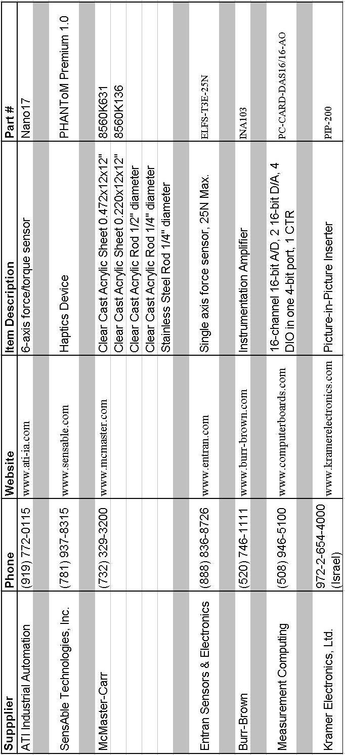
94 83
Methods for Haptic Feedback in Teleoperated Robotic Surgery
 Young Group 5 1 Methods for Haptic Feedback in Teleoperated Robotic Surgery Paper Review Jessie Young Group 5: Haptic Interface for Surgical Manipulator System March 12, 2012 Paper Selection: A. M. Okamura.
Teleoperation with Sensor/Actuator Asymmetry: Task Performance with Partial Force Feedback
 Teleoperation with Sensor/Actuator Asymmetry: Task Performance with Partial Force Wagahta Semere, Masaya Kitagawa and Allison M. Okamura Department of Mechanical Engineering The Johns Hopkins University
Analysis of Suture Manipulation Forces for Teleoperation with Force Feedback
 Analysis of Suture Manipulation Forces for Teleoperation with Force Feedback Masaya Kitagawa 1, Allison M. Okamura 1, Brian T. Bethea 2, Vincent L. Gott 2, and William A. Baumgartner 2 1 Johns Hopkins
Small Occupancy Robotic Mechanisms for Endoscopic Surgery
 Small Occupancy Robotic Mechanisms for Endoscopic Surgery Yuki Kobayashi, Shingo Chiyoda, Kouichi Watabe, Masafumi Okada, and Yoshihiko Nakamura Department of Mechano-Informatics, The University of Tokyo,
Research article Methods for haptic feedback in teleoperated robot-assisted surgery
 Research article Methods for haptic feedback in teleoperated robot-assisted surgery The author is based in the Department of Mechanical Engineering, The Johns Hopkins University, Baltimore, Maryland, USA.
Medical robotics and Image Guided Therapy (IGT) Bogdan M. Maris, PhD Temporary Assistant Professor
 Bogdan M. Maris, PhD Temporary Assistant Professor") Medical robotics and Image Guided Therapy (IGT) Bogdan M. Maris, PhD Temporary Assistant Professor E-mail bogdan.maris@univr.it Medical Robotics History, current and future applications Robots are Accurate
Medical robotics and Image Guided Therapy (IGT) Bogdan M. Maris, PhD Temporary Assistant Professor E-mail bogdan.maris@univr.it Medical Robotics History, current and future applications Robots are Accurate
Modeling and Experimental Studies of a Novel 6DOF Haptic Device
 Proceedings of The Canadian Society for Mechanical Engineering Forum 2010 CSME FORUM 2010 June 7-9, 2010, Victoria, British Columbia, Canada Modeling and Experimental Studies of a Novel DOF Haptic Device
Surgical robot simulation with BBZ console
 Review Article on Thoracic Surgery Surgical robot simulation with BBZ console Francesco Bovo 1, Giacomo De Rossi 2, Francesco Visentin 2,3 1 BBZ srl, Verona, Italy; 2 Department of Computer Science, Università
Haptic Feedback in Robot Assisted Minimal Invasive Surgery
 K. Bhatia Haptic Feedback in Robot Assisted Minimal Invasive Surgery 1 / 33 MIN Faculty Department of Informatics Haptic Feedback in Robot Assisted Minimal Invasive Surgery Kavish Bhatia University of
Wearable Haptic Feedback Actuators for Training in Robotic Surgery
 Wearable Haptic Feedback Actuators for Training in Robotic Surgery NSF Summer Undergraduate Fellowship in Sensor Technologies Joshua Fernandez (Mechanical Eng.) University of Maryland Baltimore County
Novel machine interface for scaled telesurgery
 Novel machine interface for scaled telesurgery S. Clanton, D. Wang, Y. Matsuoka, D. Shelton, G. Stetten SPIE Medical Imaging, vol. 5367, pp. 697-704. San Diego, Feb. 2004. A Novel Machine Interface for
Application of Force Feedback in Robot Assisted Minimally Invasive Surgery
 Application of Force Feedback in Robot Assisted Minimally Invasive Surgery István Nagy, Hermann Mayer, and Alois Knoll Technische Universität München, 85748 Garching, Germany, {nagy mayerh knoll}@in.tum.de,
Cutaneous Feedback of Fingertip Deformation and Vibration for Palpation in Robotic Surgery
 Cutaneous Feedback of Fingertip Deformation and Vibration for Palpation in Robotic Surgery Claudio Pacchierotti Domenico Prattichizzo Katherine J. Kuchenbecker Motivation Despite its expected clinical
Haptic Virtual Fixtures for Robot-Assisted Manipulation
 Haptic Virtual Fixtures for Robot-Assisted Manipulation Jake J. Abbott, Panadda Marayong, and Allison M. Okamura Department of Mechanical Engineering, The Johns Hopkins University {jake.abbott, pmarayong,
Elements of Haptic Interfaces
 Elements of Haptic Interfaces Katherine J. Kuchenbecker Department of Mechanical Engineering and Applied Mechanics University of Pennsylvania kuchenbe@seas.upenn.edu Course Notes for MEAM 625, University
Using Simulation to Design Control Strategies for Robotic No-Scar Surgery
 Using Simulation to Design Control Strategies for Robotic No-Scar Surgery Antonio DE DONNO 1, Florent NAGEOTTE, Philippe ZANNE, Laurent GOFFIN and Michel de MATHELIN LSIIT, University of Strasbourg/CNRS,
An Inexpensive Experimental Setup for Teaching The Concepts of Da Vinci Surgical Robot
 An Inexpensive Experimental Setup for Teaching The Concepts of Da Vinci Surgical Robot S.Vignesh kishan kumar 1, G. Anitha 2 1 M.TECH Biomedical Engineering, SRM University, Chennai 2 Assistant Professor,
Evaluation of Haptic Virtual Fixtures in Psychomotor Skill Development for Robotic Surgical Training
 Department of Electronics, Information and Bioengineering Neuroengineering and medical robotics Lab Evaluation of Haptic Virtual Fixtures in Psychomotor Skill Development for Robotic Surgical Training
Techniques of the hand tie and instrument tie
 Techniques of the hand tie and instrument tie 1. The Anatomy of a Square Knot A square knot consists of two "throws". Throws are constructed by crossing the ends of the suture to form a loop and then wrapping
Integrating PhysX and OpenHaptics: Efficient Force Feedback Generation Using Physics Engine and Haptic Devices
 This is the Pre-Published Version. Integrating PhysX and Opens: Efficient Force Feedback Generation Using Physics Engine and Devices 1 Leon Sze-Ho Chan 1, Kup-Sze Choi 1 School of Nursing, Hong Kong Polytechnic
Wireless Master-Slave Embedded Controller for a Teleoperated Anthropomorphic Robotic Arm with Gripping Force Sensing
 Wireless Master-Slave Embedded Controller for a Teleoperated Anthropomorphic Robotic Arm with Gripping Force Sensing Presented by: Benjamin B. Rhoades ECGR 6185 Adv. Embedded Systems January 16 th 2013
Measurements of the Level of Surgical Expertise Using Flight Path Analysis from da Vinci Robotic Surgical System
 Measurements of the Level of Surgical Expertise Using Flight Path Analysis from da Vinci Robotic Surgical System Lawton Verner 1, Dmitry Oleynikov, MD 1, Stephen Holtmann 1, Hani Haider, Ph D 1, Leonid
Multichannel vibrotactile display for sensory substitution during teleoperation
 2001 SPIE International Symposium on Intelligent Systems and Advanced Manufacturing, Newton, MA, 28-31 October Multichannel vibrotactile display for sensory substitution during teleoperation Thomas Debus
Towards robotic heart surgery: Introduction of autonomous procedures into an experimental surgical telemanipulator system
 74 ORIGINAL ARTICLE Towards robotic heart surgery: Introduction of autonomous procedures into an experimental surgical telemanipulator system R Bauernschmitt*, E U Schirmbeck*, A Knoll, H Mayer, I Nagy,
Haptic control in a virtual environment
 Haptic control in a virtual environment Gerard de Ruig (0555781) Lourens Visscher (0554498) Lydia van Well (0566644) September 10, 2010 Introduction With modern technological advancements it is entirely
Control design issues for a microinvasive neurosurgery teleoperator system
 Control design issues for a microinvasive neurosurgery teleoperator system Jacopo Semmoloni, Rudy Manganelli, Alessandro Formaglio and Domenico Prattichizzo Abstract This paper deals with controller design
Haptic Feedback in Laparoscopic and Robotic Surgery
 Haptic Feedback in Laparoscopic and Robotic Surgery Dr. Warren Grundfest Professor Bioengineering, Electrical Engineering & Surgery UCLA, Los Angeles, California Acknowledgment This Presentation & Research
Lecture 9: Teleoperation
 ME 327: Design and Control of Haptic Systems Autumn 2018 Lecture 9: Teleoperation Allison M. Okamura Stanford University teleoperation history and examples the genesis of teleoperation? a Polygraph is
Telemanipulation and Telestration for Microsurgery Summary
 Telemanipulation and Telestration for Microsurgery Summary Microsurgery presents an array of problems. For instance, current methodologies of Eye Surgery requires freehand manipulation of delicate structures
Medical Robotics. Part II: SURGICAL ROBOTICS
 5 Medical Robotics Part II: SURGICAL ROBOTICS In the last decade, surgery and robotics have reached a maturity that has allowed them to be safely assimilated to create a new kind of operating room. This
Chapter 2 Introduction to Haptics 2.1 Definition of Haptics
 Chapter 2 Introduction to Haptics 2.1 Definition of Haptics The word haptic originates from the Greek verb hapto to touch and therefore refers to the ability to touch and manipulate objects. The haptic
Enhanced performance of delayed teleoperator systems operating within nondeterministic environments
 University of Wollongong Research Online University of Wollongong Thesis Collection 1954-2016 University of Wollongong Thesis Collections 2010 Enhanced performance of delayed teleoperator systems operating
Harvard BioRobotics Laboratory Technical Report
 Harvard BioRobotics Laboratory Technical Report December 2 Virtual Fixtures for Robotic Endoscopic Surgery Fuji Lai & Robert D. Howe Division of Engineering and Applied Sciences Harvard University 323
da Vinci Skills Simulator
 da Vinci Skills Simulator Introducing Simulation for the da Vinci Surgical System Skills Practice in an Immersive Virtual Environment Portable. Practical. Powerful. The da Vinci Skills Simulator contains
FASTENERS, MEASUREMENTS AND CONVERSIONS
 FASTENERS, MEASUREMENTS AND CONVERSIONS Bolts, Nuts and Other Threaded Retainers Although there are a great variety of fasteners found in the modern car or truck, the most commonly used retainer is the
Robust Haptic Teleoperation of a Mobile Manipulation Platform
 Robust Haptic Teleoperation of a Mobile Manipulation Platform Jaeheung Park and Oussama Khatib Stanford AI Laboratory Stanford University http://robotics.stanford.edu Abstract. This paper presents a new
Robotic System Simulation and Modeling Stefan Jörg Robotic and Mechatronic Center
 Robotic System Simulation and ing Stefan Jörg Robotic and Mechatronic Center Outline Introduction The SAFROS Robotic System Simulator Robotic System ing Conclusions Folie 2 DLR s Mirosurge: A versatile
Computer Assisted Medical Interventions
 Outline Computer Assisted Medical Interventions Force control, collaborative manipulation and telemanipulation Bernard BAYLE Joint course University of Strasbourg, University of Houston, Telecom Paris
INSTRUCTION MANUAL. In vivo Test Apparatus for 305B Muscle Lever Systems
 INSTRUCTION MANUAL Model 806A In vivo Test Apparatus for 305B Muscle Lever Systems May 18, 2005, Revision 3 Copyright 2005 Aurora Scientific Inc. Aurora Scientific Inc. 360 Industrial Parkway S., Unit
Effect of Force Feedback on Performance of Robotics-Assisted Suturing
 The Fourth IEEE RAS/EMBS International Conference on Biomedical Robotics and Biomechatronics Roma, Italy. June 24-27, 2012 Effect of Force Feedback on Performance of Robotics-Assisted Suturing Ali Talasaz,
Differences in Fitts Law Task Performance Based on Environment Scaling
 Differences in Fitts Law Task Performance Based on Environment Scaling Gregory S. Lee and Bhavani Thuraisingham Department of Computer Science University of Texas at Dallas 800 West Campbell Road Richardson,
Performance Analysis of Steady-Hand Teleoperation versus Cooperative Manipulation
 Performance Analysis of Steady-Hand Teleoperation versus Cooperative Manipulation Izukanne Emeagwali, Panadda Marayong, Jake J. Abbott, and Allison M. Okamura Engineering Research Center for Computer-Integrated
The Haptic Impendance Control through Virtual Environment Force Compensation
 The Haptic Impendance Control through Virtual Environment Force Compensation OCTAVIAN MELINTE Robotics and Mechatronics Department Institute of Solid Mechanicsof the Romanian Academy ROMANIA octavian.melinte@yahoo.com
Jane Li. Assistant Professor Mechanical Engineering Department, Robotic Engineering Program Worcester Polytechnic Institute
 Jane Li Assistant Professor Mechanical Engineering Department, Robotic Engineering Program Worcester Polytechnic Institute Use an example to explain what is admittance control? You may refer to exoskeleton
Evaluation of Five-finger Haptic Communication with Network Delay
 Tactile Communication Haptic Communication Network Delay Evaluation of Five-finger Haptic Communication with Network Delay To realize tactile communication, we clarify some issues regarding how delay affects
Surgeon-Tool Force/Torque Signatures - Evaluation of Surgical Skills in Minimally Invasive Surgery
 # J. Rosen et al. Surgeon-Tool Force/Torque Signatures Surgeon-Tool Force/Torque Signatures - Evaluation of Surgical Skills in Minimally Invasive Surgery Jacob Rosen +, Ph.D., Mark MacFarlane *, M.D.,
Nonholonomic Haptic Display
 Nonholonomic Haptic Display J. Edward Colgate Michael A. Peshkin Witaya Wannasuphoprasit Department of Mechanical Engineering Northwestern University Evanston, IL 60208-3111 Abstract Conventional approaches
The Effect of Haptic Degrees of Freedom on Task Performance in Virtual Surgical Environments
 The Effect of Haptic Degrees of Freedom on Task Performance in Virtual Surgical Environments Jonas FORSSLUND a,1, Sonny CHAN a,1, Joshua SELESNICK b, Kenneth SALISBURY a,c, Rebeka G. SILVA d, and Nikolas
University of Alabama at Birmingham. ObGyn Residency. Laparoscopy Training Lab PGY 1-4. Individual Pelvic Trainer Tasks
 University of Alabama at Birmingham ObGyn Residency Laparoscopy Training Lab PGY 1-4 Individual Pelvic Trainer Tasks 2010-2011 Skill 1: Peg Board (Blue Board) Goal: Pick up various rings and move them
AC : MEDICAL ROBOTICS LABORATORY FOR BIOMEDICAL ENGINEERS
 AC 2008-1272: MEDICAL ROBOTICS LABORATORY FOR BIOMEDICAL ENGINEERS Shahin Sirouspour, McMaster University http://www.ece.mcmaster.ca/~sirouspour/ Mahyar Fotoohi, Quanser Inc Pawel Malysz, McMaster University
Image Guided Robotic Assisted Surgical Training System using LabVIEW and CompactRIO
 Image Guided Robotic Assisted Surgical Training System using LabVIEW and CompactRIO Weimin Huang 1, Tao Yang 1, Liang Jing Yang 2, Chee Kong Chui 2, Jimmy Liu 1, Jiayin Zhou 1, Jing Zhang 1, Yi Su 3, Stephen
DISTAL RADIUS PLATES 3.5 mm / ANGULARLY STABLE. Distal radius plates 3,5 mm / angularly stable. Locking bone screws. Cortical bone screw
 SURGICAL NÁSTROJE TECHNIQUE PRO ARTROSKOPII DISTAL INSTRUMENTS RADIUS PLATES FOR ARTHROSCOPY 3.5 mm / ANGULARLY STABLE Distal radius plates 3.5 mm / angularly stable Indication The plates are used for
EXPERIMENTAL BILATERAL CONTROL TELEMANIPULATION USING A VIRTUAL EXOSKELETON
 EXPERIMENTAL BILATERAL CONTROL TELEMANIPULATION USING A VIRTUAL EXOSKELETON Josep Amat 1, Alícia Casals 2, Manel Frigola 2, Enric Martín 2 1Robotics Institute. (IRI) UPC / CSIC Llorens Artigas 4-6, 2a
Bibliography. Conclusion
 the almost identical time measured in the real and the virtual execution, and the fact that the real execution with indirect vision to be slower than the manipulation on the simulated environment. The
Development of a Master Slave Combined Manipulator for Laparoscopic Surgery
 Development of a Master Slave Combined Manipulator for Laparoscopic Surgery Functional Model and Its Evaluation Makoto Jinno 1, Nobuto Matsuhira 1, Takamitsu Sunaoshi 1 Takehiro Hato 1, Toyomi Miyagawa
Date Issued: 12/13/2016 iarmc.06: Draft 6. TEAM 1 - iarm CONTROLLER FUNCTIONAL REQUIREMENTS
 Date Issued: 12/13/2016 iarmc.06: Draft 6 TEAM 1 - iarm CONTROLLER FUNCTIONAL REQUIREMENTS 1 Purpose This document presents the functional requirements for an accompanying controller to maneuver the Intelligent
Developing Frogger Player Intelligence Using NEAT and a Score Driven Fitness Function
 Developing Frogger Player Intelligence Using NEAT and a Score Driven Fitness Function Davis Ancona and Jake Weiner Abstract In this report, we examine the plausibility of implementing a NEAT-based solution
MEAM 520. Haptic Rendering and Teleoperation
 MEAM 520 Haptic Rendering and Teleoperation Katherine J. Kuchenbecker, Ph.D. General Robotics, Automation, Sensing, and Perception Lab (GRASP) MEAM Department, SEAS, University of Pennsylvania Lecture
A Feasibility Study of Time-Domain Passivity Approach for Bilateral Teleoperation of Mobile Manipulator
 International Conference on Control, Automation and Systems 2008 Oct. 14-17, 2008 in COEX, Seoul, Korea A Feasibility Study of Time-Domain Passivity Approach for Bilateral Teleoperation of Mobile Manipulator
2. Introduction to Computer Haptics
 2. Introduction to Computer Haptics Seungmoon Choi, Ph.D. Assistant Professor Dept. of Computer Science and Engineering POSTECH Outline Basics of Force-Feedback Haptic Interfaces Introduction to Computer
Chapter 1 Introduction
 Chapter 1 Introduction It is appropriate to begin the textbook on robotics with the definition of the industrial robot manipulator as given by the ISO 8373 standard. An industrial robot manipulator is
Travis Bishop. Submitted to: Dr. John Davis. Date: 3 December Course: ETME 310 Section: 004. Lab Topic: Milling Project (Vise)
") Travis Bishop Submitted to: Dr. John Davis Date: 3 December 2012 Course: ETME 310 Section: 004 Lab Topic: Milling Project (Vise) Introduction: Purpose of Experiment: This experiment was conducted to teach
Travis Bishop Submitted to: Dr. John Davis Date: 3 December 2012 Course: ETME 310 Section: 004 Lab Topic: Milling Project (Vise) Introduction: Purpose of Experiment: This experiment was conducted to teach
VBOSS. Surgical Technique. Vertebral Body Support System
 VBOSS Surgical Technique Vertebral Body Support System 1. System Description 1.1 Implants...3 1.2 Instruments...4 2. Indications...8 3. Patient Position...8 4. Surgical Approach 4.1 Choice of adequate
Lecture 1: Introduction to haptics and Kinesthetic haptic devices
 ME 327: Design and Control of Haptic Systems Winter 2018 Lecture 1: Introduction to haptics and Kinesthetic haptic devices Allison M. Okamura Stanford University today s objectives introduce you to the
MEAM 520. Haptic Rendering and Teleoperation
 MEAM 520 Haptic Rendering and Teleoperation Katherine J. Kuchenbecker, Ph.D. General Robotics, Automation, Sensing, and Perception Lab (GRASP) MEAM Department, SEAS, University of Pennsylvania Lecture
Shape Memory Alloy Actuator Controller Design for Tactile Displays
 34th IEEE Conference on Decision and Control New Orleans, Dec. 3-5, 995 Shape Memory Alloy Actuator Controller Design for Tactile Displays Robert D. Howe, Dimitrios A. Kontarinis, and William J. Peine
Design and Development of Novel Two Axis Servo Control Mechanism
 Design and Development of Novel Two Axis Servo Control Mechanism Shailaja Kurode, Chinmay Dharmadhikari, Mrinmay Atre, Aniruddha Katti, Shubham Shambharkar Abstract This paper presents design and development
Force feedback interfaces & applications
 Force feedback interfaces & applications Roope Raisamo Tampere Unit for Computer-Human Interaction (TAUCHI) School of Information Sciences University of Tampere, Finland Based on material by Jukka Raisamo,
LASER ASSISTED COMBINED TELEOPERATION AND AUTONOMOUS CONTROL
 ANS EPRRSD - 13 th Robotics & remote Systems for Hazardous Environments 11 th Emergency Preparedness & Response Knoxville, TN, August 7-10, 2011, on CD-ROM, American Nuclear Society, LaGrange Park, IL
Robots in the Field of Medicine
 Robots in the Field of Medicine Austin Gillis and Peter Demirdjian Malden Catholic High School 1 Pioneers Robots in the Field of Medicine The use of robots in medicine is where it is today because of four
Peter Berkelman. ACHI/DigitalWorld
 Magnetic Levitation Haptic Peter Berkelman ACHI/DigitalWorld February 25, 2013 Outline: Haptics - Force Feedback Sample devices: Phantoms, Novint Falcon, Force Dimension Inertia, friction, hysteresis/backlash
Measurement Of The Magnitude And Direction Of The Electric Field Of A Mobile Phone In The Near Field
 Measurement Of The Magnitude And Direction Of The Electric Field Of A Mobile Phone In The Near Field Pantinakis A. and E. Batsaki E. Department of Sciences, Physics Section, Technical University of Crete,
Effects of Geared Motor Characteristics on Tactile Perception of Tissue Stiffness
 Effects of Geared Motor Characteristics on Tactile Perception of Tissue Stiffness Jeff Longnion +, Jacob Rosen+, PhD, Mika Sinanan++, MD, PhD, Blake Hannaford+, PhD, ++ Department of Electrical Engineering,
Performance Issues in Collaborative Haptic Training
 27 IEEE International Conference on Robotics and Automation Roma, Italy, 1-14 April 27 FrA4.4 Performance Issues in Collaborative Haptic Training Behzad Khademian and Keyvan Hashtrudi-Zaad Abstract This
Laboratory 1: Uncertainty Analysis
 University of Alabama Department of Physics and Astronomy PH101 / LeClair May 26, 2014 Laboratory 1: Uncertainty Analysis Hypothesis: A statistical analysis including both mean and standard deviation can
VerroTouch: High-Frequency Acceleration Feedback for Telerobotic Surgery
 University of Pennsylvania ScholarlyCommons Departmental Papers (MEAM) Department of Mechanical Engineering & Applied Mechanics 7-2010 VerroTouch: High-Frequency Acceleration Feedback for Telerobotic Surgery
SMart wearable Robotic Teleoperated surgery
 SMart wearable Robotic Teleoperated surgery This project has received funding from the European Union s Horizon 2020 research and innovation programme under grant agreement No 732515 Context Minimally
Chapter 1. Introduction
 Chapter 1 Introduction Robotics technology has recently found extensive use in surgical and therapeutic procedures. The purpose of this chapter is to give an overview of the robotic tools which may be
GE 101 Final Design Project:
 GE 101 Final Design Project: Clear Point Mechanical Pencil Presented and Submitted on: Monday May 8, 2009 Sarah Fullmer David Montiel Wonseok Oh Ryan Smith Table of Contents Table of Contents... ii List
Maneuverability Evaluation of a Surgical Robot for Single-Port Surgery
 International Journal of Pharma Medicine and Biological Sciences Vol. 5, No. 1, January 2016 Maneuverability Evaluation of a Surgical Robot for Single-Port Surgery Katsuaki Oiwa, Shotaro Maeda, and Chiharu
Right Angle Screwdriver
 Right Angle Screwdriver October 12, 2009 Team: Scott Carpenter - Team Leader Chuck Donaldson - Communicator Nate Retzlaff - BWIG John McGuire - BSAC Client: Ashish Mahajan, MD Resident Plastic and Reconstructive
Salient features make a search easy
 Chapter General discussion This thesis examined various aspects of haptic search. It consisted of three parts. In the first part, the saliency of movability and compliance were investigated. In the second
Flexible Hypotubes: Lasers Enable Medical Device Delivery. Flexible Hypotubes
 : Lasers Enable Medical Device Delivery Flexible Tubes David Gillen, Blueacre Technology As medicine advances, surgeons are always seeking to access further into the human body. Minimally invasive, or
Experimental evaluation of magnified haptic feedback for robot-assisted needle insertion and palpation
 1 Experimental evaluation of magnified haptic feedback for robot-assisted needle insertion and palpation Leonardo Meli, Claudio Pacchierotti, and Domenico Prattichizzo Abstract Background: Haptic feedback
MN Modelling Objects and Creating Manufacturing Strategy
 Abstract This document and the accompanying files describe the process of modelling a bell housing jig using the 3D software Catia V5. The manufacturing process by which the bell housing would be created
Instructions for Use. LCP Locking Compression Plate. Combine without Compromise.
 Instructions for Use LCP Locking Compression Plate. Combine without Compromise. Table of Contents LCP: Combine without Compromise 2 AO ASIF Principles of Osteosynthesis 4 Indications and Contraindications
Tri- State Consulting Co. Engineering 101 Project # 2 Catapult Design Group #
 Tri- State Consulting Co. Engineering 101 Project # 2 Catapult Design Group # 8 12-03-02 Executive Summary The objective of our second project was to design and construct a catapult, which met certain
Technique Guide. Variable Angle LCP Opening Wedge Plates 2.4/2.7. Part of the Variable Angle LCP Forefoot / Midfoot System 2.4 / 2.7.
 Technique Guide Variable Angle LCP Opening Wedge Plates 2.4/2.7. Part of the Variable Angle LCP Forefoot / Midfoot System 2.4 / 2.7. Table of Contents Introduction Variable Angle LCP Opening Wedge Plates
Design and Operation of a Force-Reflecting Magnetic Levitation Coarse-Fine Teleoperation System
 IEEE International Conference on Robotics and Automation, (ICRA 4) New Orleans, USA, April 6 - May 1, 4, pp. 4147-41. Design and Operation of a Force-Reflecting Magnetic Levitation Coarse-Fine Teleoperation
An Excavator Simulator for Determining the Principles of Operator Efficiency for Hydraulic Multi-DOF Systems Mark Elton and Dr. Wayne Book ABSTRACT
 An Excavator Simulator for Determining the Principles of Operator Efficiency for Hydraulic Multi-DOF Systems Mark Elton and Dr. Wayne Book Georgia Institute of Technology ABSTRACT This paper discusses
A Machine Tool Controller using Cascaded Servo Loops and Multiple Feedback Sensors per Axis
 A Machine Tool Controller using Cascaded Servo Loops and Multiple Sensors per Axis David J. Hopkins, Timm A. Wulff, George F. Weinert Lawrence Livermore National Laboratory 7000 East Ave, L-792, Livermore,
Haptic Camera Manipulation: Extending the Camera In Hand Metaphor
 Haptic Camera Manipulation: Extending the Camera In Hand Metaphor Joan De Boeck, Karin Coninx Expertise Center for Digital Media Limburgs Universitair Centrum Wetenschapspark 2, B-3590 Diepenbeek, Belgium
"Internet Telescope" Performance Requirements
 "Internet Telescope" Performance Requirements by Dr. Frank Melsheimer DFM Engineering, Inc. 1035 Delaware Avenue Longmont, Colorado 80501 phone 303-678-8143 fax 303-772-9411 www.dfmengineering.com Table
Laser-Assisted Telerobotic Control for Enhancing Manipulation Capabilities of Persons with Disabilities
 The 2010 IEEE/RSJ International Conference on Intelligent Robots and Systems October 18-22, 2010, Taipei, Taiwan Laser-Assisted Telerobotic Control for Enhancing Manipulation Capabilities of Persons with
The Haptic Perception of Spatial Orientations studied with an Haptic Display
 The Haptic Perception of Spatial Orientations studied with an Haptic Display Gabriel Baud-Bovy 1 and Edouard Gentaz 2 1 Faculty of Psychology, UHSR University, Milan, Italy gabriel@shaker.med.umn.edu 2
Intracorporeal Knot-Tying and Suturing Techniques in Laparoscopic Surgery: Technical Details
 Intracorporeal Knot-Tying and Suturing Techniques in Laparoscopic Surgery: Technical Details E. Croce, MD, S. Olmi, MD ABSTRACT Background: Intracorporeal suturing and knot-tying in laparoscopic surgery
ROOP LAL Unit-6 Lathe (Turning) Mechanical Engineering Department
 Mechanical Engineering Department") Notes: Lathe (Turning) Basic Mechanical Engineering (Part B) 1 Introduction: In previous Lecture 2, we have seen that with the help of forging and casting processes, we can manufacture machine parts of
Notes: Lathe (Turning) Basic Mechanical Engineering (Part B) 1 Introduction: In previous Lecture 2, we have seen that with the help of forging and casting processes, we can manufacture machine parts of
ERC: Engineering Research Center for Computer- Integrated Surgical Systems and Technology (NSF Grant # )
") ERC: Engineering Research Center for Computer- Integrated Surgical Systems and Technology (NSF Grant #9731748) MARCIN BALICKI 1, and TIAN XIA 2 1,2 Johns Hopkins University, 3400 Charles St., Baltimore,
ERC: Engineering Research Center for Computer- Integrated Surgical Systems and Technology (NSF Grant #9731748) MARCIN BALICKI 1, and TIAN XIA 2 1,2 Johns Hopkins University, 3400 Charles St., Baltimore,
CHAPTER 2. RELATED WORK 9 similar study, Gillespie (1996) built a one-octave force-feedback piano keyboard to convey forces derived from this model to
 built a one-octave force-feedback piano keyboard to convey forces derived from this model to") Chapter 2 Related Work 2.1 Haptic Feedback in Music Controllers The enhancement of computer-based instrumentinterfaces with haptic feedback dates back to the late 1970s, when Claude Cadoz and his colleagues
Chapter 2 Related Work 2.1 Haptic Feedback in Music Controllers The enhancement of computer-based instrumentinterfaces with haptic feedback dates back to the late 1970s, when Claude Cadoz and his colleagues
II. TELEOPERATION FRAMEWORK. A. Forward mapping
 tracked using a Leap Motion IR camera (Leap Motion, Inc, San Francisco, CA, USA) and the forces are displayed on the fingertips using wearable thimbles. Cutaneous feedback provides the user with a reliable