IMPORTANT WARRANTY & INSTALLATION INSTRUCTIONS ATTACHED
|
|
|
- Amy Morrison
- 6 years ago
- Views:
Transcription

1 IMPORTANT WARRANTY & INSTALLATION INSTRUCTIONS ATTACHED Please Forward All Attached Information to Consumer Warranty Not Valid Unless Returned to Volant Performance STOP

2 Please take time to read and understand these installation instructions. Volant recommends that the installation of this system be performed by a qualified service center or professional installer who has the necessary equipment, tools and experienced personnel. However, if you decide to perform this install the use of an additional person may be required. CAUTION: Never work on a hot engine bay. Allow time for the vehicle to cool. Recommended Tools: Flathead Screwdriver 8mm and 10mm Sockets T-27 and T-20 Torx Drivers Ratchet Ratchet Extension Please confirm that all parts are present according to the bill of materials before beginning the installation. 1 Plastic air box 4 ¼ x 5/8 Rubber washers 1 3.5in Hump hose 1 Plastic air duct 4 ¼ -20 x.50 Truss head screw 1 6mm x 25 Bolt 1 Pro filter 1 MAF sensor gasket 2 1/4 x 7/8in Fender washers 1 Aluminum air box lid 2 #56 Stainless clamps 1 1/4in Lock washers 1 Lid gasket 2 4mm x 10 Pan head screws 2 10mm Nut 1 Filter box adapter in Silicon sleeve 2 #48 Clamps 1 Volant Bracket Trim Sponge 1 1/2 NPT fitting 1 5/8 Straight fitting 24in 5/8 Breather hose 3 Pan head screws 3 #10 Lock washers 3 #10 washers 1 L Bracket
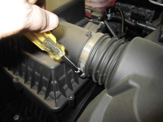
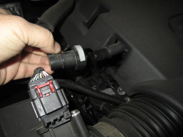
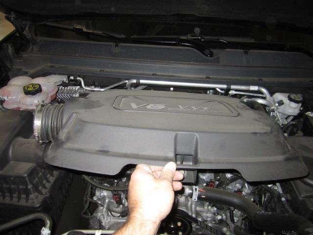
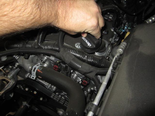
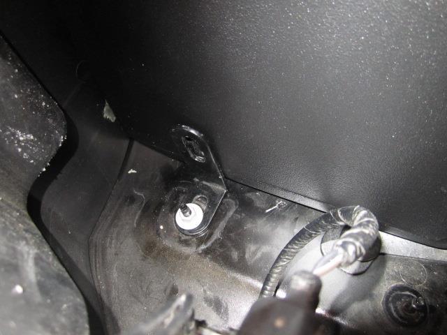
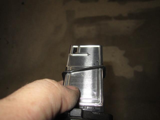
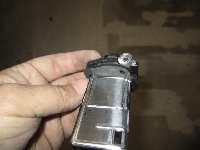
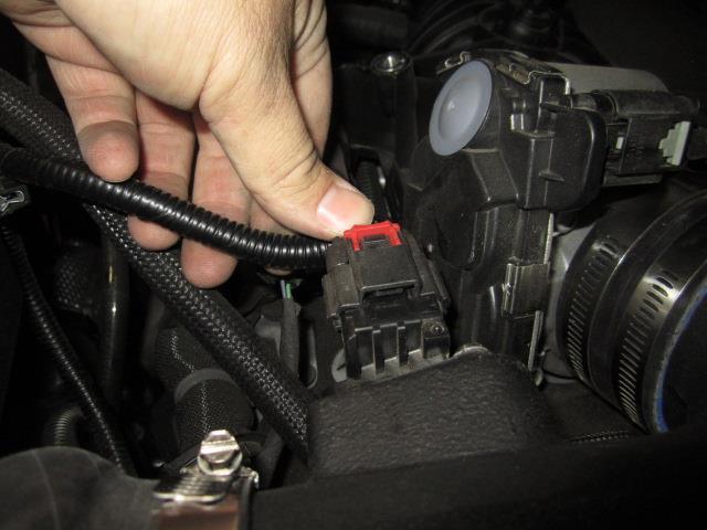
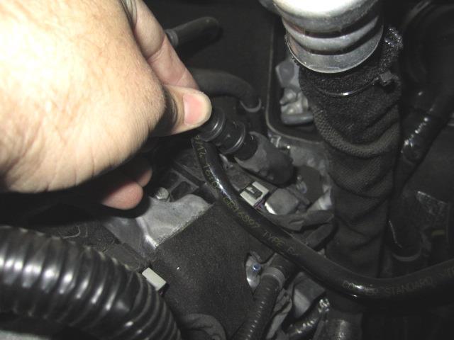
3 Installation Instructions: 1. Disconnect both of the negative battery cables, failure to disconnect these cables can result in a CEL and/or damage to the motor. (Fig A) 2. Disconnect the crankcase breather hose from the resonator box. (Fig B) 3. Remove the crankcase breather hose from the back of the resonator box. (Fig C) 4. Remove the oil fill cap. Save for reinstallation. (Fig D) 5. Remove the MAF sensor harness from the factory air box and disconnect the harness from the MAF sensor. (Fig E) 6. Loosen the clamp holding the air duct to the air box. (Fig F) 7. Remove the duct from the air box. (Fig G) 8. Remove the two 10mm nuts holding the air box in place. Save one for reinstallation. (Fig H) 9. Remove the T27 bolt holding the resonator box to the passenger's side of the engine. (Fig I) 10. Remove the two 8mm bolts holding the resonator box to the rear of the engine. (Fig J) 11. Loosen the clamp holding the air duct to the throttle body. (Fig K) 12. Remove the factory resonator box from the engine compartment. (Fig L) 13. Remove the factory air box from the engine compartment. (Fig M) 14. Reinstall the factory oil fill cap. (Fig N) 15. Remove the hard plastic breather line from the rubber connection to the motor, leave the rubber fitting in place. (Fig O) 16. Press the trim sponge onto the Volant air box fender opening. (Fig P) 17. Press the Volant box fitting into the factory rubber grommet. (Fig Q) 18. Loosely attach the short arm of the supplied bracket onto the wheel well using the factory nut. (Fig R) 19. Tighten the long arm to the Volant box using the provided hardware. (Fig S) 20. Finish tightening the short arm of the bracket. (Fig T)
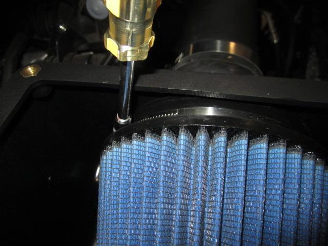
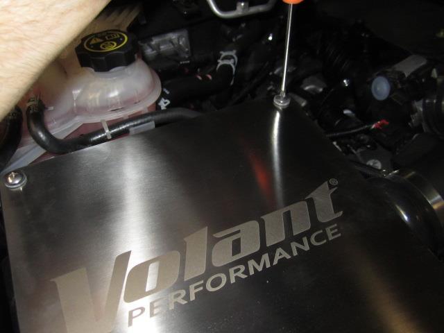
4 21. Attach the 3.00 sleeve to the throttle body using the #48 clamp with a 5/16 socket or nut driver only. (Fig U) 22. Attach the 3.50 hump hose onto the air box adapter using the #56 clamp with a 5/16 socket or nut driver only. (Fig V) 23. Remove the MAF sensor from the factory air box then remove the factory MAF sensor gasket. (Fig W) 24. Place the supplied MAF gasket onto the MAF sensor. (Fig X) 25. Tighten the MAF sensor onto the Volant duct using the hardware provided. (Fig Y) 26. Press the Volant duct into the hump hose then loosely tighten it in place with the provided #56 clamp. (Fig Z) 27. Press the Volant duct into the sleeve and tighten into place using a #48 with a 5/16 socket or nut driver only. (Fig AA) 28. Tighten the hump hose in place using a 5/16 socket or nut driver only. (Fig BB) 29. Attach the MAF sensor harness to the MAF sensor. (Fig CC) 30. Press the supplied 5/8 fitting into the factory rubber crankcase hose adapter. (Fig DD) 31. Press the supplied 5/8 breather hose line onto the Volant air duct. (Fig EE) 32. Press the breather hose onto the 5/8 straight fitting. (Fig FF) 33. Attach the 5119 Pro5 filter onto the adapter using a 5/16 socket or nut driver only. (Fig GG) 34. Attach the Volant lid to the box using the hardware provided. 35. Reconnect the battery cables and double check all connections before driving. *Check that this air intake complies with your Federal, State and Local laws. We recommend saving your stock system. BEFORE ROAD TESTING 1. Start engine, leaving the transmission in park and securing the parking brake. 2. Make sure to look and listen for any unusual noises or air leaks. Repair problems if needed. 3. Once completed it will be necessary to check periodically, after a few heat cycles, for realignment and tightening of all connections. CARE AND CLEANING If using the Primo cotton reusable filter periodically and remove any excessive dirt build-up by tapping the filter on the ground and brushing off the loosened dirt. Clean the filter by using a two stage cleaning kit to thoroughly clean and reoil the filter. Re-oil every 10,000 miles without cleaning to improve filtering in sand and dirt. Clean only when dirt is very excessive or 50,000 miles. PICTURES ON NEXT PAGE


5 Fig. A Fig. B Fig. C Fig. D Fig. E Fig. F CONTINUED ON NEXT PAGE


6 Fig. G Fig. H Fig. I Fig. J Fig. L Fig. K CONTINUED ON NEXT PAGE


7 Fig. M Fig. N Fig. O Fig. P Fig. Q Fig. R CONTINUED ON NEXT PAGE


8 Fig. S Fig. T Fig. U Fig. V Fig. W Fig. X CONTINUED ON NEXT PAGE


9 Fig. Y Fig. Z Fig. AA Fig. BB Fig. CC Fig. DD CONTINUED ON NEXT PAGE


10 Fig. EE Fig. FF Fig. GG Fig. HH
IMPORTANT WARRANTY & INSTALLATION INSTRUCTIONS ATTACHED
 IMPORTANT WARRANTY & INSTALLATION INSTRUCTIONS ATTACHED Please Forward All Attached Information to Consumer Warranty Not Valid Unless Returned to Volant Performance STOP For Full-Color Installation Instructions,
IMPORTANT WARRANTY & INSTALLATION INSTRUCTIONS ATTACHED
 IMPORTANT WARRANTY & INSTALLATION INSTRUCTIONS ATTACHED Please Forward All Attached Information to Consumer Warranty Not Valid Unless Returned to Volant Performance STOP For Full-Color Installation Instructions
IMPORTANT WARRANTY & INSTALLATION INSTRUCTIONS ATTACHED
 IMPORTANT WARRANTY & INSTALLATION INSTRUCTIONS ATTACHED Please Forward All Attached Information to Consumer Warranty Not Valid Unless Returned to Volant Performance STOP Please be sure to review the enclosed
IMPORTANT WARRANTY & INSTALLATION INSTRUCTIONS ATTACHED
 IMPORTANT WARRANTY & INSTALLATION INSTRUCTIONS ATTACHED Please Forward All Attached Information to Consumer Warranty Not Valid Unless Returned to Volant Performance For Full-Color Installation Instructions,
IMPORTANT WARRANTY & INSTALLATION INSTRUCTIONS ATTACHED
 IMPORTANT WARRANTY & INSTALLATION INSTRUCTIONS ATTACHED Please Forward All Attached Information to Consumer Warranty Not Valid Unless Returned to Volant Performance STOP For Full-Color Installation Instructions,
IMPORTANT WARRANTY & INSTALLATION INSTRUCTIONS ATTACHED
 IMPORTANT WARRANTY & INSTALLATION INSTRUCTIONS ATTACHED Please Forward All Attached Information to Consumer Warranty Not Valid Unless Returned to Volant Performance STOP Please be sure to review the enclosed
IMPORTANT WARRANTY & INSTALLATION INSTRUCTIONS ATTACHED
 IMPORTANT WARRANTY & INSTALLATION INSTRUCTIONS ATTACHED Please Forward All Attached Information to Consumer Warranty Not Valid Unless Returned to Volant Performance Please be sure to review the enclosed
IMPORTANT WARRANTY & INSTALLATION INSTRUCTIONS ATTACHED
 IMPORTANT WARRANTY & INSTALLATION INSTRUCTIONS ATTACHED Please Forward All Attached Information to Consumer Warranty Not Valid Unless Returned to Volant Performance STOP For Full-Color Installation Instructions,
IMPORTANT WARRANTY & INSTALLATION INSTRUCTIONS ATTACHED
 IMPORTANT WARRANTY & INSTALLATION INSTRUCTIONS ATTACHED Please Forward All Attached Information to Consumer Warranty Not Valid Unless Returned to Volant Performance For Full-Color Installation Instructions,
IMPORTANT WARRANTY & INSTALLATION INSTRUCTIONS ATTACHED
 IMPORTANT WARRANTY & INSTALLATION INSTRUCTIONS ATTACHED For Full-Color Installation Instructions, Please Visit: VOLANT.COM and Search by Part Number Please be sure to review the enclosed instructions prior
IMPORTANT INSTALLATION INSTRUCTIONS ATTACHED
 IMPORTANT INSTALLATION INSTRUCTIONS ATTACHED For Full-Color Installation Instructions, Please Visit: VOLANT.COM and Search by Part Number Please be sure to review the enclosed instructions prior to beginning
IMPORTANT WARRANTY & INSTALLATION INSTRUCTIONS ATTACHED
 IMPORTANT WARRANTY & INSTALLATION INSTRUCTIONS ATTACHED For Full-Color Installation Instructions, Please Visit: VOLANT.COM and Search by Part Number Please be sure to review the enclosed instructions prior
IMPORTANT WARRANTY & INSTALLATION INSTRUCTIONS ATTACHED
 IMPORTANT WARRANTY & INSTALLATION INSTRUCTIONS ATTACHED Please Forward All Attached Information to Consumer Warranty Not Valid Unless Returned to Volant Performance STOP Please be sure to review the enclosed
Recommended Tools: 5/16 nut driver or socket 11mm nut driver or socket Flathead Screwdriver
 Please take time to read and understand these installation instructions. CORSA recommends that the installation of this system be performed by a qualified service center or professional installer who has
IMPORTANT WARRANTY & INSTALLATION INSTRUCTIONS ATTACHED
 IMPORTANT WARRANTY & INSTALLATION INSTRUCTIONS ATTACHED Please Forward All Attached Information to Consumer Warranty Not Valid Unless Returned to Volant Performance STOP For Full-Color Installation Instructions,
IMPORTANT WARRANTY & INSTALLATION INSTRUCTIONS ATTACHED
 IMPORTANT WARRANTY & INSTALLATION INSTRUCTIONS ATTACHED Please Forward All Attached Information to Consumer Warranty Not Valid Unless Returned to CORSA Performance We ask that you take a few moments to
INSTALLATION INSTRUCTIONS Unitronic Intercooler Upgrade Kit for 2.0 TSI Gen3 MQB UH009-ICA
 Unitronic recommends that you read through the entire installation instructions prior to beginning the installation to familiarize yourself with the included components, tools required, and procedures
PRODUCT: TJ Corner Guards READ INSTRUCTIONS IN FULL BEFORE INSTALLATION. QUESTIONS? CALL M-F 7:00 AM 5:00 PM PST
 PRODUCT: TJ Corner Guards READ INSTRUCTIONS IN FULL BEFORE INSTALLATION. QUESTIONS? CALL 916-631-8071 M-F 7:00 AM 5:00 PM PST The MetalCloak experience includes the ease of installation of our products.
MODULAR BUMPER INSTALLATION MANUAL
 MODULAR BUMPER INSTALLATION MANUAL Parts List* 1 Center section 1 Side extension, passenger / right 1 Side extension, driver / left 1 Side cap, passenger / right 1 Side cap, driver / left 1 Brush guard,
Medium HoneyBadger Chase Rack Installation Instructions
 PREPARATION Medium HoneyBadger Chase Rack Installation Instructions 1. Disconnect the negative terminal on the battery. Park the vehicle on level ground and set the emergency brake. 2. We recommend reading
PROVEN WORLDWIDE SNORKEL FOR CHEVY COLORADO NEW PRODUCT
 AEV30272AC Last Updated: 10/09/18 PROVEN WORLDWIDE SNORKEL FOR CHEVY COLORADO NEW PRODUCT Please visit www.aev-conversions.com to view the most current installation guide for this product. This is a new
Fig A. ADDICTIVE DESERT DESIGNS Preparation: Installation:
 Preparation: Disconnect the negative battery terminal. Park the vehicle on level ground and set the emergency brake. We recommend reading through the installation instructions in whole before performing
INSTALLATION MANUAL FRONT. See pages 2 and 3 of this manual for configuration options. Level of Difficulty. Product Photo (center section only)
") INSTALLATION MANUAL FRONT Level of Difficulty Moderate Product Photo (center section only) All hardware listed below will be provided with the bumpers center section. Additional hardware will be supplied
INSTALLATION MANUAL FRONT Level of Difficulty Moderate Product Photo (center section only) All hardware listed below will be provided with the bumpers center section. Additional hardware will be supplied
55000/55010 Installation Instructions
 A. Install 55015 B. Bolt roof rails, 55020/55025, to front hoop. C. Assemble 55026 D. To install without drilling into bumper. E. If mounting directly to bumper. A. 55015 Installation Instructions 55000/55010
SAFETY THIS PRODUCT IS FOR OFFROAD USE ONLY. ALL LIABILITY FOR INSTALLATION AND USE RESTS WITH THE OWNER.
 SAFETY Your safety and the safety of others is very important. In order to help you make informed decisions about safety, we have provided installation instructions and other information. These instructions
BOX-117 E-Z-Go RXV Utility Box Mounting Kit Installation Instructions
 BOX-117 E-Z-Go RXV Utility Box Mounting Kit Installation Instructions Contents of BOX-117 Utility Box Mounting Kit: a (1 ea.) Utility Box Support Frame, Driver Side b (1 ea.) Utility Box Support Frame,
Please read BOTH these Installation Instructions and the General Instructions prior to installing or operating this equipment.
 Attachment Tab Height: 13 Attachment Tab Width: 24 Please read BOTH these and the General Instructions prior to installing or operating this equipment. Serial Number 1. Blue Ox towing products and accessories
To install new top weight plate bushings in G7 strength units.
 1/5 PURPOSE To install new top weight plate bushings in G7 strength units. RE-WORK PARTS REQUIRED - ZMS4000424 Top Weight Plate Bushing (Quantity 4 per machine). - Matrix Top Weight Plate Bushing Removal
Be sure any accessory used will fit with the soft upper doors before installing. Not all accessories will be compatible.
 Company Name: Spike Power Sports Vehicle Name: Polaris General 2P Product Description: Soft Upper Doors Part Number: 58-1600 Revision: R01 09/19/2018 Contents: 655 Elm Ridge Ave, Canal Fulton OH, 44614
BOX-115 Club Car Precedent Utility Box Mounting Kit Installation Instructions
 BOX-115 Club Car Precedent Utility Box Mounting Kit Installation Instructions Contents of BOX-115 Utility Box Mounting Kit: a (1 ea.) Utility Box Support Frame, Passenger Side b (1 ea.) Utility Box Support
INSTALLATION INSTRUCTIONS KK-K9-C12-K CHEVY IMPALA
 INSTALLATION INSTRUCTIONS KK-K9-C12-K 2000-2005 CHEVY IMPALA READ ALL INSTRUCTIONS PRIOR TO INSTALLATION TOOLS REQUIRED: Power Drill Drill bits1/4 and 5/32 7/l6 wrench and socket 15,18 and\or 19mm socket
INSTALLATION INSTRUCTIONS KK-K9-F14-K K9 KIT FOR FORD EXPEDITION
 INSTALLATION INSTRUCTIONS KK-K9-F14-K-32 32 K9 KIT FOR 2003-2016 FORD EXPEDITION TOOLS REQUIRED: Power Drill Drill Bit Set Standard & Metric Socket Sets Phillips Screw Driver Open End Wrench Set Wire Cutters
Please read BOTH these Installation Instructions and the General Towing Instructions before attempting to install or operate this equipment.
 2005-08 Pontiac G6 GT Please read BOTH these and the General Towing Instructions before attempting to install or operate this equipment. 1. Blue Ox towing products and accessories are intended to be installed
2017 Current Ford Raptor ADD Pro Front Bumper Installation Instructions
 2017 Current Ford Raptor ADD Pro Front Bumper Installation Instructions PREPARATION 1. Disconnect the negative terminal on the battery. Park the vehicle on level ground and set the emergency brake. 2.
2016 Current Toyota Tacoma HoneyBadger Front Bumper Installation Instructions
 2016 Current Toyota Tacoma HoneyBadger Front Bumper Installation Instructions PREPARATION 1. Disconnect the negative terminal on the battery. Park the vehicle on level ground and set the emergency brake.
BOX-118 E-Z-Go TXT Utility Box Mounting Kit Installation Instructions
 BOX-118 E-Z-Go TXT Utility Box Mounting Kit Installation Instructions Contents of BOX-118 Utility Box Mounting Kit: a (1 ea.) Utility Box Support Frame, Driver Side b (1 ea.) Utility Box Support Frame,
E4-WM5-Y525A00 MOUNTING INSTRUCTION
 RAM 2500/3500 4WD B8 5100 (Dual Steering Damper Kit) The installation of these steering dampers must be performed only by experienced and qualified personnel. Read and follow the installation instructions
Ford Raptor Venom Front Bumper Installation Instructions
 PREPARATION 2010 2014 Ford Raptor Venom Front Bumper Installation Instructions 1. Disconnect the negative terminal on the battery. Park the vehicle on level ground and set the emergency brake. 2. We recommend
FENDER FLARE INSTALLATION
 Customer Support TM FENDER FLARE INSTALLATION TG-FF8C4108 IMPORTANT TYGER only approves the installation according to our instructions with the hardware provided. WARNING Failure to complete the installation
WARNING Honda Pilot Installation Instructions BX2244. Serial Number
 Please read BOTH these and the General Instructions before attempting to install or operate this equipment. Serial Number 1. Blue Ox towing products and accessories are intended to be installed by Blue
Horizontal Cable Systems
 ALUMINUM RAILING INSTALLATION INSTRUCTIONS Horizontal Cable Systems 1) Check Contents Of Packages: Verify that all parts have arrived and that they match the packing list. 1A) Coastal applications: Confirm
INSTRUCTIONS. INTERCOOLER UPGRADE BMW E82 135i 2008-
 INSTRUCTIONS INTERCOOLER UPGRADE BMW E82 135i 2008- Parts Included: - Intercooler - 4 door shield - 2-45 degree Silicone Hoses ( 2.5 x 3 ) - 1 2.5x3 silicone straight hose. - 1 45 degree aluminum pipe
BX2173 Installation Instructions Ford Focus (including the 2.3L engine) 2003 Ford Focus SVT
 2003 Ford Focus SVT") BX2173 Installation Instructions 2000-04 Ford Focus (including the 2.3L engine) 2003 Ford Focus SVT Serial No. The front fascia, coolant line bracket and anti-pollution devices are removed for baseplate
BX2173 Installation Instructions 2000-04 Ford Focus (including the 2.3L engine) 2003 Ford Focus SVT Serial No. The front fascia, coolant line bracket and anti-pollution devices are removed for baseplate
SEAT-361 E-Z-Go RXV RHOX Seat Kit Installation Instructions
 SEAT-361 E-Z-Go RXV RHOX Seat Kit Installation Instructions Contents of SEAT-361 RHOX 300 Series Rear Seat Kit: a (1 ea.) Front Seat Back Support, Driver Side b (1 ea.) Front Seat Back Support, Passenger
Rugged Ridge Engine Transmission Skid Plate JK
 Installation Time: 1-2 Hours Tools Required: Rugged Ridge Engine Transmission Skid Plate 2012-2017 JK Sockets: 16mm, 17mm, 18mm deep well Socket Wrench Wrenches: 16mm, 18mm Torque Wrench Drill ½ Drill
WARNING. Bolt Torque Specifications Torque in Foot-Pounds for Inch Bolts Bolt Size Grade 5 Grade 8
 1. Blue Ox towing products and accessories are intended to be installed by Blue Ox Dealers who are familiar with our products and have the equipment and knowledge necessary to do fit work. If needed, Blue
Barricade Trail Force HD Rear Bumper w/ Tire Carrier installation (07-16 Wrangler JK)
") Barricade Trail Force HD Rear Bumper w/ Tire Carrier installation (07-16 Wrangler JK) Installation Time: 2-3 Hours Tools Required: Tire iron Ratcheting socket set (ratchet plus 13, 16, 19mm sockets) Open
Barricade Trail Force HD Rear Bumper w/ Tire Carrier installation (07-16 Wrangler JK) Installation Time: 2-3 Hours Tools Required: Tire iron Ratcheting socket set (ratchet plus 13, 16, 19mm sockets) Open
FLAT PANEL CART WITH OR WITHOUT A PULL OUT SHELF
 FP42UL FP60UL FP42MUL FP60MUL FLAT PANEL CART WITH OR WITHOUT A PULL OUT SHELF WARNING: FP42 carts are intended to hold monitors up to 75 lbs and FP60 carts are intended to hold monitors up to 100 lbs.
INSTALLATION INSTRUCTIONS
 Do not attempt to install this product on any vehicle other than the one it is designed for and listed above! Parts List 10 3/8 X 1 1/4 Hex Bolt 10 3/8 Lock Washer 4 3/8 Hex Nut 4 3/8 Flat Washer 2 3169)
Rugged Ridge Front Bumper Winch Plate JK
 Rugged Ridge Front Bumper Winch Plate 13-17 JK Note: These instructions involve cutting parts of your vehicle. Please read all instructions prior to starting. Installation Time: 2-3 Hours Tools Required:
STRAIGHT HANDLEBAR KIT
 STRAIGHT HANDLEBAR KIT P/N 2881973 APPLICATION All straight bar applications, excluding 550 Indy and Voyageur models BEFORE YOU BEGIN Read these instructions and check to be sure all parts and tools are
**MOUNTING YOUR MONITOR
 FPP72V200 72 FREE STANDING DISPLAY CART Assembly Instructions Hardware List Ref. Qty. Part No. Description AA 4 030-1128 1/4-20 UNC, 1 3/4 Socket Hd Screws BB 1 030-1129 5/8-11 UNC 1 3/4 Socket Hd Screw
JK Front Crusher Flares
 INSTALLATION INSTRUCTIONS INST-17-03-030_A JK Front Crusher Flares IMPORTANT: Thank you for purchasing this Poison Spyder product. Please read through this entire document before proceeding with installation.
Intercooler Shroud and Belt Cover for WRX
 Intercooler Shroud and Belt Cover for 2015+ WRX 2016-05-18 Thank you for purchasing this PERRIN product for your car! Installation of this product should only be performed by persons experienced with installation
INSTALLATION INSTRUCTIONS
 INSTALLATION INSTRUCTIONS SPORTSMAN WINCH MOUNT GRILLE GUARD APPLICATION: 2016-2018 Toyota Tacoma PART NUMBER: 40-93885, 45-93880, 46-23885 ITEM QUANTITY DESCRIPTION TOOLS NEEDED 1 1 WINCH TRAY 15MM SOCKET
MAG-CONV Basic, 48, 48R & Midline Front Mount
 Parts Required: Tools Used: Mag Wheels Brakes Brake Rods Mounting Bracket Anti Tippers 7/16" Wrench Screw Driver Rubber Mallet 5/8 Wrench 5mm Allen Wrench Step Execution Figures 1 Remove front 5" total
HANDLEBAR KIT P/N APPLICATION BEFORE YOU BEGIN KIT CONTENTS TOOLS REQUIRED. Instr Rev Page 1 of 6
 HANDLEBAR KIT P/N 2881993 APPLICATION All straight bar applications, excluding 550 Indy and Voyageur models BEFORE YOU BEGIN Read these instructions and check to be sure all parts and tools are accounted
INSTALLATION INSTRUCTIONS K9-C20-32 & K9-C CHEVROLET 4 DOOR TAHOE, GMC YUKON, SUBURBAN and YULON XL
 INSTALLATION INSTRUCTIONS K9-C20-32 & K9-C21-32 2007-2014 CHEVROLET 4 DOOR TAHOE, GMC YUKON, SUBURBAN and YULON XL TOOLS REQUIRED: Power drill Drill bit set Standard & metric socket sets Phillips screwdriver
IN 578. Tools Required. Torque Specification: 10mm Socket 7/16 Socket 1/2 Socket 1/2 Wrench 7/16 Wrench 1/8 Allen Wrench.
 Tools Required 2011-C Ford F250/F350 No Drilling into Vehicle is Required 10mm Socket 7/16 Socket 1/2 Socket 1/2 Wrench 7/16 Wrench 1/8 Allen Wrench FL277 x 1 Torque Specification: 1/4 Bolts - 6 Ft Lbs.
Assembly Instructions BBQ400
 Assembly Instructions BBQ400 DOC035 REV C PARTS LIST PART PREVIEW DESCRIPTION QTY PART# ID# 1/4-20 SHOULDER BOLT LONG 4 HDW154 A WASHER 1/2OD X 1/4 ID FLAT ZINC 38 HDW072 B TOP SECTION 1 C 1/4-20 x.625
BMW E39/E53 Android Touch Screen Radio Installation Instructions
 BMW E9/E5 Android Touch Screen Radio Installation Instructions Enjoy your new Android Radio from Bremmen Parts, we appreciate your business. Vibrant Touch Display This radio features a responsive 9 touch
JK FRONT FENDER FLARE INSTALLATION INSTRUCTIONS
 JK FRONT FENDER FLARE INSTALLATION INSTRUCTIONS TOOLS NEEDED 3/16 Allen Wrench 1/2 Socket or wrench 10mm Socket Flat head screwdriver HARDWARE 5/16 x 3/4 button heads (14) 5/16 x 1 button heads (8) 5/16
TOYOTA COROLLA EC REARVIEW MIRROR Section I Installation Preparation
 Section I Installation Preparation Part Number: PT374-02030 Section I Installation Preparation Kit Contents Item # Quantity Reqd. Description 1 1 AD Mirror Assembly w/compass & Maplights 2 1 Hardware Bag
1. Remove factory stock bump stop and mount from the frame.
 1. Disconnect the negative terminal on the battery. With the vehicle on level ground and the emergency brake set, block the front tires. 2. Jack up the rear of the vehicle and support the frame rails with
Katerack Wagon Shelving System
 Ford Transit Connect Assembly Installation Instructions Sheet 1 of 14 BEFORE YOU START! IMPORTANT INSTALLATION STEPS ARE DENOTED USING A STOP SIGN. THESE STEPS MUST BE PERFORMED IN THE SPECIFIED ORDER
ADDICTIVE DESERT DESIGNS
 Preparation: Disconnect the negative battery terminal. Park the vehicle on level ground and set the emergency brake. We recommend reading through the installation instructions in whole before performing
2012+ F30 320i, 328i F22 228i Carbon Fiber S-FLO Intake INSTALLATION GUIDE FOR RACING USE ONLY
 PERFORMNCE ENGINEERING FOR EUROPEN UTOS INSTLLTION GUIDE 2012+ F30 320i, 328i 2014+ F22 228i Carbon Fiber S-FLO Intake FOR RCING USE ONLY Congratulations on your purchase of the WE Tuning Carbon Fiber
Installation Guide for Rough Country 1.25 inch Body Lift Kit w/o Shocks (07-15 Wrangler JK 4 Door) Item # J10048 Option B; Manual
 Item # J10048 Option B; Manual") Installation Guide for Rough Country 1.25 inch Body Lift Kit w/o Shocks (07-15 Wrangler JK 4 Door) Item # J10048 Option B; Manual Installation Time: 3 Hours Tools Required: Jack (Tall enough to reach body
Installation Guide for Rough Country 1.25 inch Body Lift Kit w/o Shocks (07-15 Wrangler JK 4 Door) Item # J10048 Option B; Manual Installation Time: 3 Hours Tools Required: Jack (Tall enough to reach body
2015 Current Ford F150/Raptor Adaptive Cruise Control Module Relocation Bracket Installation Instructions
 2015 Current Ford F150/Raptor Adaptive Cruise Control Module Relocation Bracket Installation Instructions PREPARATION 1. Disconnect the negative terminal on the battery. Park the vehicle on level ground
Fig A ADDICTIVE DESERT DESIGNS. Preparation: Removal:
 Preparation: Disconnect the negative battery terminal. Park the vehicle on level ground and set the emergency brake. We recommend reading through the installation instructions in whole before performing
FENDER FLARE INSTALLATION
 Part#: TG-FF8G4158 FOR 2007-2013 GMC Sierra 1500 Pickup Truck (Exclude 69.3inch Short Bed Models) FENDER FLARE INSTALLATION Hardware Kit Included IMPORTANT TYGER only approves the installation according
Please read BOTH these Installation Instructions and the General Instructions prior to installing or operating this equipment.
 Attachment Tab Height: 16-1/2 Serial Number Attachment Tab Width: 24 Please read BOTH these and the General Instructions prior to installing or operating this equipment. 1. Blue Ox towing products and
C4 Fabrication Rock Slider Installation 14+ 5th Gen 4Runner w/o KDSS
 C4 Fabrication Rock Slider Installation 14+ 5th Gen 4Runner w/o KDSS Thank you for your purchase of the C4 Fabrication s 5th Gen 4Runner Rock Sliders! This product was carefully crafted to ensure a perfect
RUN-IN SHED INSTRUCTIONS
 RUN-IN SHED INSTRUCTIONS 14321 5th Line Nassagaweya, Rockwood, ON, N0B 2K0 Phone 519-856-9959 ~ Fax 519-856-4141 Toll Free 1-800-461-3362 ~ Email sales@systemhorse.com Website www.systemfence.com RUN-IN
Installation Instructions Precision Sport Shifter
 Installation Instructions Precision Sport Shifter 2004 and up Pontiac GTO Part Number 45043 2010, 2005, 2004 by B&M Racing and Performance Products This B&M Precision Sport Shifter has been designed to
General Prisoner Transport Install Instructions PT-2-INST
 General Prisoner Transport Install Instructions PT-2-INST 50 or 60 high x 80, 100 & 120 inch long / Double Compartment Inserts Also refer to PT-A-3XX instructions for vehicle specific mounting measurements
Rear Mount Installation Instructions
 Rear Mount Installation Instructions Ford Transit Low Roof 130 WB Frame Kit Part #: DTC 0809-011 V1.0.10.12.18 IMPORTANT INSTALLATION STEPS ARE DENOTED USING A STOP SIGN. THESE STEPS MUST BE PERFORMED
WARNING Saturn Astra Installation Instructions BX3333. Serial Number
 Please read BOTH these and the General Instructions before attempting to install or operate this equipment. Serial Number 1. Blue Ox towing products and accessories are intended to be installed by Blue
Fig A 2. Using a 10mm Socket, remove the two bolts referenced in (Fig B). Save these bolts for reuse. Fig B ADDICTIVE DESERT DESIGNS.
. Save these bolts for reuse. Fig B ADDICTIVE DESERT DESIGNS.") Preparation: Disconnect the negative battery terminal. Park the vehicle on level ground and set the emergency brake. We recommend reading through the installation instructions in whole before performing
Preparation: Disconnect the negative battery terminal. Park the vehicle on level ground and set the emergency brake. We recommend reading through the installation instructions in whole before performing
SAFETY THIS PRODUCT IS FOR OFFROAD USE ONLY. ALL LIABILITY FOR INSTALLATION AND USE RESTS WITH THE OWNER.
 SAFETY Your safety and the safety of others is very important. In order to help you make informed decisions about safety, we have provided installation instructions and other information. These instructions
Ram Promaster Rack. Installation instructions for
 Installation instructions for Ram Promaster Rack MyGlassTruck.com 200 Acorn Road LOCAL 856-595-9069 WEB www.myglasstruck.com Glassboro, NJ 08028 FAX 856-863-1480 1-844-364-4022 Version 1.0 November 2015
3/4 Rear DuraRac Installation Instructions
 3/4 Rear DuraRac Installation Instructions Ford Transit Low Roof 130 WB Frame Kit Part #: CRC 27-1010-001 V1.0.09.28.18 IMPORTANT INSTALLATION STEPS ARE DENOTED USING A STOP SIGN. THESE STEPS MUST BE PERFORMED
Elite Series Fender Flares
 Page 1 of 8 Installation Instructions I - Sheet Number I606RPG Rev.B Important Safety Information Tools Required Contents Elite Series Fender Flares Preparation Before Painting / Installation NOTE Actual
ABM International, Inc.
 ABM International, Inc. Lightning Stitch required 1 1.0: Parts List head and motor assembly (Qty. 1) Reel stand (Qty. 1) Needle bar frame clamp (Qty. 1) Motor drive (Qty. 1) 2 Cable harness with bracket
INSTRUCTIONS INSTRUCCIONES CONSIGNES
 AUTOMOTIVE PRODUCTS, INC. INSTRUCTIONS INSTRUCCIONES CONSIGNES APPLICATION: GMC SIERRA 1500 HDX & SPORTSMAN GRILLE GUARDS (2014 & UP) APPLICATION PART # S 57-3690, 57-3695, 40-3695, 45-3690 ITEM QUANTITY
FM2113PC/FM2114PC SBC Top Mount Alt, w/ A/C & Power Steering
 10) At this time assemble the power steering bracket and pump assembly from the instructions provided with the power steering bracket beginning at step 7. Return to step 10 on this sheet when complete.
All Terrain Flares 09+ Ford F150
 Page 1/5 Components: 1. Front Flares (2) 2. Front Flare Inner Pieces (2) 3. Rear Flares (2) Tools required: - Utility knife - Electric Drill - 1/4 Drill Bit - #2 Phillips driver - Socket wrench Hardware
CORVETTE Page 1 of 12 CORVETTE C
 CORVETTE 2005-2006 Page 1 of 12 CORVETTE C5 1997-2004 THIS KIT INCLUDES: 8 M8-1.25X40MM BOLTS WITH WASHERS 8 M8-1.25X30MM BOLTS WITH WASHERS RIGHT AND LEFT HINGE ASSEMBLY WIRE LOOM 2 SHOCKS 565 PSI 2 SHOULDER
FM2113PC/FM2114PC SBC Top Mount Alt, w/ A/C & Power Steering
 10) At this time assemble the power steering bracket and pump assembly from the instructions provided with the power steering bracket beginning at step 7. Return to step 10 on this sheet when complete.
FENDER FLARE INSTALLATION
 TG-FF8T4178: Fit 2014-UP Toyota Tundra PRIOR TO INSTALLATION IMPORTANT Tyger only approves the installation according to our instructions with the hardware provided. WARNING Failure to complete the installation
SAFETY THIS PRODUCT IS FOR OFFROAD USE ONLY. ALL LIABILITY FOR INSTALLATION AND USE RESTS WITH THE OWNER.
 SAFETY Your safety and the safety of others is very important. In order to help you make informed decisions about safety, we have provided installation instructions and other information. These instructions
KWIK-KIT KK-S INSTALLATION INSTRUCTION PACKAGE
 KWIK-KIT KK-S-120-02 INSTALLATION INSTRUCTION PACKAGE INSTALLATION INSTRUCTIONS HAVIS KWIK-KIT KK-S-120-02 2002-2007 DODGE/FREIGHTLINER SPRINTER VAN PLEASE READ COMPLETE INSTRUCTIONS PRIOR TO INSTALLATION
INSTALL INSTRUCTIONS KK & KK KWIK-KIT PRISONER TRANSPORT INSERT FORD and CHEVY VAN PRISONER TRANSPORT
 INSTALL INSTRUCTIONS KK-100-03 & KK-120-03 KWIK-KIT PRISONER TRANSPORT INSERT FORD and CHEVY VAN PRISONER TRANSPORT TOOLS REQUIRED: ¼ & 3/8 Ratcheting Wrenches ¼ & 3/8 Air Ratchets (recommended) 3/8 Impact
Conflicts Note: Drop-in Bed liner
 Toyota Tundra 2015 LED Bed Lights Preparation Part Number: 00016-34089 Accessory Code: BU1000 Conflicts Note: Drop-in Bed liner Kit Contents Item # Quantity Reqd. Description 1 1 Hardware Kit 2 1 Driver
PPM-5710 JK HEAVY DUTY SKID PLATE ASSEMBLY Version 2.0
 SYNERGY MFG. 870 INDUSTRIAL WAY, SAN LUIS OBISPO, CA (805) 242-0397 PPM-5710 JK HEAVY DUTY SKID PLATE ASSEMBLY Version 2.0 GENERAL NOTES: These instructions are also available on our website; www.synergymfg.com.
THIS KIT INCLUDES: 8 M8-1.25X40MM BOLTS WITH WASHERS 8 M8-1.25X30MM BOLTS WITH WASHERS RIGHT AND LEFT HINGE
 Sal es@lambodoorscanada. com 2407A Kal adarave,ottawa,on K1V 8B9 THIS KIT INCLUDES: 8 M8-1.25X40MM BOLTS WITH WASHERS 8 M8-1.25X30MM BOLTS WITH WASHERS RIGHT AND LEFT HINGE 2 SHOCKS 565 PSI 2 SHOULDER
TOYOTA TACOMA LED BED LIGHTS Preparation
 Preparation Part Number: PT948-35160 Kit Contents Item # Quantity Reqd. Description 1 1 Hardware Kit 2 1 Driver Side LED assembly 3 1 Passenger Side LED assembly 4 1 Main Wire Harness Hardware Bag Contents
Sea Doo Spark Engine Access Kit
 Sea Doo Spark Engine Access Kit PART# - RS4-130-EAK APPLICATION(S): Sea Doo Spark. 2up & 3up Models. We strongly recommend the use of a service manual to familiarize yourself with the various components
MOTORIZED STANDARD SHADE WITH CABLES Installation Instructions
 Tools Needed Drill Measuring Tape Pencil 2 Level Plumb Line ¼ Masonry Drill Bit Hammer Linesmans Pliers Cable Cutters Phillips & Flat-Head Screw Driver 11/32 Socket or Open End Wrench 5/32 Allen Wrench
INSTALLATION INSTRUCTIONS
 INSTALLATION INSTRUCTIONS SNYPER TUBULAR FENDERS APPLICATION: 2007-2017 Jeep Wrangler JK PART NUMBER: 62-1005, 62-1015 ITEM QUANTITY DESCRIPTION TOOLS NEEDED 1,2 2 FRONT FENDERS, DRIVER (1) AND PASSENGER