IMPORTANT WARRANTY & INSTALLATION INSTRUCTIONS ATTACHED
|
|
|
- Wilfrid Underwood
- 6 years ago
- Views:
Transcription
1 IMPORTANT WARRANTY & INSTALLATION INSTRUCTIONS ATTACHED Please Forward All Attached Information to Consumer Warranty Not Valid Unless Returned to Volant Performance Please be sure to review the enclosed instructions prior to beginning the installation process.


2 Please take time to read and understand these installation instructions. Volant recommends that the installation of this system be performed by a qualified service center or professional installer who has the necessary equipment, tools and experienced personnel. However, if you decide to perform this install the use of an additional person may be required. CAUTION: Never work on a hot engine bay. Allow time for the vehicle to cool. Recommended Tools: Flathead Screwdriver Assorted Socket Set Ratchet Ratchet Extension Please confirm that all parts are present according to the bill of materials before beginning the installation. Bill of Materials 1 Plastic air box 4 ¼ x 5/8 rubber washers 2 1/4 Nuts 1 ATS sensor plate gasket 1 Plastic air duct 4 ¼ 20 x.50 Truss head screw 2 #64 Clamps 1 Battery tray 1 Air box lid 2 1/4 x 20 Bolts in Straight sleeve 1 V Logo 1 Lid gasket 2 ¼ Lock washers 1 1/2 Rubber grommet 4 #4 screws Primo filter 2 ¼ x 20 Washers 1 ATS sensor plate 40 Vinyl trim sponge 2
 2.")
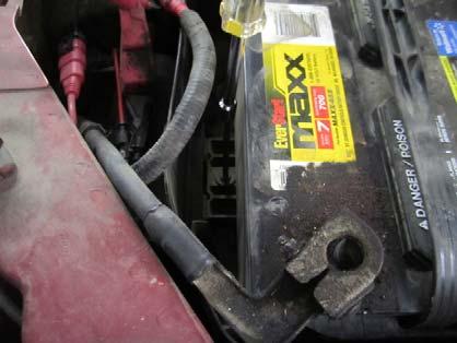
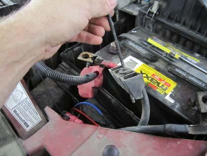
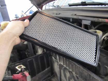
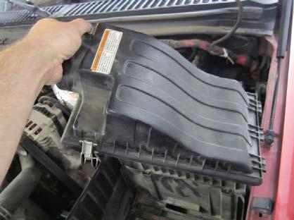
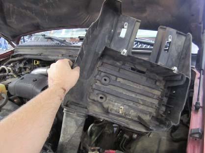
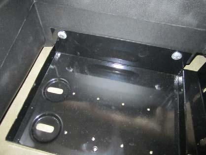
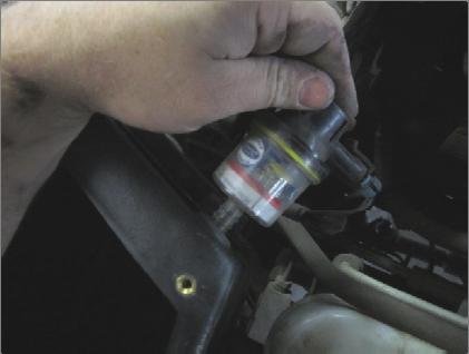
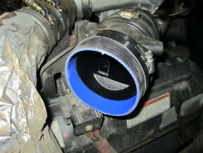
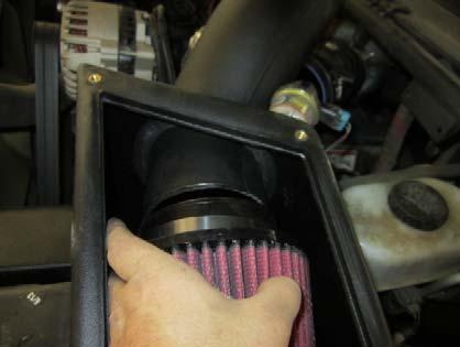
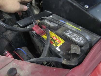
3 Installation Instructions: Locate your vehicle s battery and disconnect the negative battery cable, this resets the computer and clears old air flow data to prevent CEL errors. 1. Check all hardware before installing the Volant system, Volant recommends keeping the OEM kit in case the vehicle needs to be returned to stock. (Fig A) 2. Disconnect the negative battery cables on both batteries. (Fig B) 3. Disconnect both positive battery cables on both batteries. (Fig C) 4. Unsnap the driver's side battery cover. (Fig D) 5. Remove the Battery cover. (Fig E) 6. Using a 5/16 socket or nut driver loosen the battery hold down bolt. (Fig F) 7. Remove the battery hold down bracket and bolt. Remove the battery from the engine compartment. (Fig G) 8. Remove the filter minder by pulling it straight out of the factory rubber grommet. (Fig H) 9. Loosen the clamp holding the duct to the air box. (Fig I) 10. Loosen the clamp holding the duct to the turbo inlet pipe. (Fig J) 11. Remove the factory air duct. (Fig K) 12. Unclip the factory air box top and remove it. (Fig L) 13. Remove the filter from the Factory air box. (Fig M) 14. Remove the ATS sensor from the back of the air box by twisting and pulling straight out. (Fig N) 15. Remove the 2 bolts from the bottom of the air box. (Fig O) 16. Remove the 2 bolts holding the air box to the battery tray. (Fig P) 17. Remove the factory air box. (Fig Q) 18. Remove the 4 13mm bolts holding the battery tray in place. (Fig R) 19. Remove the factory battery tray. (Fig S) 3
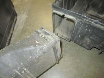
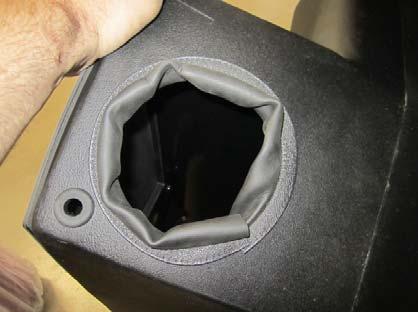
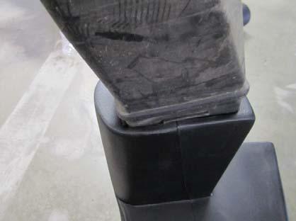
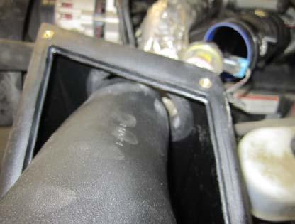
4 20. If equipped remove the factory intake piping from the front of the air box. (Fig T) 21. If the vehicle does not have this inlet pipe it can be purchased from your local dealership. (Fig U) 22. Remove the plastic bag containing the juke padding material from the fender well. (Fig V) WARNING: Over tightening hardware may alter the integrity of the CORSA air intake system. 23. Press the 23.5 trim sponge onto the fender opening on the Volant box. (Fig W) 24. Press the 16.5 trim sponge onto the air duct opening on the Volant box. (Fig X) 25. Press the factory intake pipe into the Volant box. (Fig Y) 26. Hand tighten the 2 1/4 x 20 bolts into the Volant box making sure the nuts are on the inside of the Volant box. (Fig Z) 27. Install the Volant system into the factory position. (Fig AA) 28. Using the factory 13mm bolts attach the Volant battery tray onto the fender by hand. (Fig BB) 29. Using the factory 13mm bolts attach the Volant battery tray onto the wheel well by hand. (Fig CC) 30. Tighten the 1/4 x 20 bolts holding the tray to the Volant box. (Fig DD) 31. Press the ATS sensor into the Volant box and rotate the sensor a quarter turn. (Fig EE) 32. Press the filter minder into the Volant rubber grommet. NOTE: The filter minder is no longer functional read care and cleaning instructions below for service information. (Fig FF) 33. Place the battery onto the Volant tray. Do not connect the cables at this time. (Fig GG) 34. Tighten down the battery in place using the factory hold down bracket and stud. (Fig HH) 35. Press the Volant filter into the Volant box. (Fig II) 36. Attach the 4 x 2.5in sleeve to the turbo inlet using a supplied #64 clamp. (Fig JJ) 37. Slide the Volant duct threw the top of the air box and out of the round hole leaving enough of the duct in the box to attach the filter. (Fig KK) 38. Attach the Volant 5153 filter onto the Volant duct. (Fig LL) 39. Slide the Volant duct into the sleeve on the turbo ducting. (Fig MM) 4
 42. Attach the Air box lid using the provided truss screws and rubber washers. (Fig PP) 43. Reconnect the battery cables. (Fig QQ) 44.")

5 40. Tighten the filter in place using a 5/16 socket or nut driver only. (Fig NN) 41. Tighten the Volant ducting to the sleeve with the provided #64 clamp using a socket or nut driver only. (Fig OO) 42. Attach the Air box lid using the provided truss screws and rubber washers. (Fig PP) 43. Reconnect the battery cables. (Fig QQ) 44. Attach the supplied CARB decal in plain sight for visual inspection test. (Fig RR) *Check that this air intake complies with your Federal, State and Local laws. We recommend saving your stock system. BEFORE ROAD TESTING 1. Start engine, leaving the transmission in park and securing the parking brake. 2. Make sure to look and listen for any unusual noises or air leaks. Repair problems if needed. 3. Once completed it will be necessary to check periodically, after a few heat cycles, for realignment and tightening of all connections. CARE AND CLEANING Check the Pro 5 cotton reusable filter periodically and remove any excessive dirt build up by tapping the filter on the ground and brushing off the loosened dirt. Clean the filter by using a two stage cleaning kit to thoroughly clean and reoil the filter. Re oil every 10,000 miles without cleaning to improve filtering in sand and dirt. Clean only when dirt is very excessive or 50,000 miles. Fig. A Fig. B 5


6 Fig. C Fig. D Fig. E Fig. F Fig. G Fig. H 6


7 Fig. I Fig. J Fig. K Fig. L Fig. M Fig. N 7


8 Fig. O Fig. P Fig. Q Fig. R Fig. S Fig. T 8


9 Fig. U Fig. V Fig. W Fig. X Fig. Y Fig. Z 9


10 Closed Box Air Intake System Fig. AA Fig. CC Fig. EE Fig. BB Fig. DD Fig. FF 10


11 Fig. GG Fig. HH Fig. II Fig. JJ Fig. KK Fig. LL 11


12 Fig. MM Fig. NN Fig. OO Fig. PP Fig. QQ Fig. RR 3/26/
IMPORTANT WARRANTY & INSTALLATION INSTRUCTIONS ATTACHED
 IMPORTANT WARRANTY & INSTALLATION INSTRUCTIONS ATTACHED Please Forward All Attached Information to Consumer Warranty Not Valid Unless Returned to Volant Performance STOP Please take time to read and understand
IMPORTANT WARRANTY & INSTALLATION INSTRUCTIONS ATTACHED
 IMPORTANT WARRANTY & INSTALLATION INSTRUCTIONS ATTACHED Please Forward All Attached Information to Consumer Warranty Not Valid Unless Returned to Volant Performance STOP For Full-Color Installation Instructions
IMPORTANT WARRANTY & INSTALLATION INSTRUCTIONS ATTACHED
 IMPORTANT WARRANTY & INSTALLATION INSTRUCTIONS ATTACHED Please Forward All Attached Information to Consumer Warranty Not Valid Unless Returned to Volant Performance STOP Please be sure to review the enclosed
IMPORTANT WARRANTY & INSTALLATION INSTRUCTIONS ATTACHED
 IMPORTANT WARRANTY & INSTALLATION INSTRUCTIONS ATTACHED Please Forward All Attached Information to Consumer Warranty Not Valid Unless Returned to Volant Performance STOP For Full-Color Installation Instructions,
IMPORTANT WARRANTY & INSTALLATION INSTRUCTIONS ATTACHED
 IMPORTANT WARRANTY & INSTALLATION INSTRUCTIONS ATTACHED Please Forward All Attached Information to Consumer Warranty Not Valid Unless Returned to Volant Performance STOP For Full-Color Installation Instructions,
IMPORTANT WARRANTY & INSTALLATION INSTRUCTIONS ATTACHED
 IMPORTANT WARRANTY & INSTALLATION INSTRUCTIONS ATTACHED Please Forward All Attached Information to Consumer Warranty Not Valid Unless Returned to Volant Performance For Full-Color Installation Instructions,
IMPORTANT WARRANTY & INSTALLATION INSTRUCTIONS ATTACHED
 IMPORTANT WARRANTY & INSTALLATION INSTRUCTIONS ATTACHED Please Forward All Attached Information to Consumer Warranty Not Valid Unless Returned to Volant Performance STOP Please be sure to review the enclosed
IMPORTANT WARRANTY & INSTALLATION INSTRUCTIONS ATTACHED
 IMPORTANT WARRANTY & INSTALLATION INSTRUCTIONS ATTACHED For Full-Color Installation Instructions, Please Visit: VOLANT.COM and Search by Part Number Please be sure to review the enclosed instructions prior
IMPORTANT WARRANTY & INSTALLATION INSTRUCTIONS ATTACHED
 IMPORTANT WARRANTY & INSTALLATION INSTRUCTIONS ATTACHED Please Forward All Attached Information to Consumer Warranty Not Valid Unless Returned to Volant Performance STOP For Full-Color Installation Instructions,
IMPORTANT WARRANTY & INSTALLATION INSTRUCTIONS ATTACHED
 IMPORTANT WARRANTY & INSTALLATION INSTRUCTIONS ATTACHED For Full-Color Installation Instructions, Please Visit: VOLANT.COM and Search by Part Number Please be sure to review the enclosed instructions prior
IMPORTANT WARRANTY & INSTALLATION INSTRUCTIONS ATTACHED
 IMPORTANT WARRANTY & INSTALLATION INSTRUCTIONS ATTACHED Please Forward All Attached Information to Consumer Warranty Not Valid Unless Returned to Volant Performance For Full-Color Installation Instructions,
Recommended Tools: 5/16 nut driver or socket 11mm nut driver or socket Flathead Screwdriver
 Please take time to read and understand these installation instructions. CORSA recommends that the installation of this system be performed by a qualified service center or professional installer who has
IMPORTANT INSTALLATION INSTRUCTIONS ATTACHED
 IMPORTANT INSTALLATION INSTRUCTIONS ATTACHED For Full-Color Installation Instructions, Please Visit: VOLANT.COM and Search by Part Number Please be sure to review the enclosed instructions prior to beginning
IMPORTANT WARRANTY & INSTALLATION INSTRUCTIONS ATTACHED
 IMPORTANT WARRANTY & INSTALLATION INSTRUCTIONS ATTACHED Please Forward All Attached Information to Consumer Warranty Not Valid Unless Returned to CORSA Performance We ask that you take a few moments to
INSTALLATION INSTRUCTIONS Unitronic Intercooler Upgrade Kit for 2.0 TSI Gen3 MQB UH009-ICA
 Unitronic recommends that you read through the entire installation instructions prior to beginning the installation to familiarize yourself with the included components, tools required, and procedures
2012+ F30 320i, 328i F22 228i Carbon Fiber S-FLO Intake INSTALLATION GUIDE FOR RACING USE ONLY
 PERFORMNCE ENGINEERING FOR EUROPEN UTOS INSTLLTION GUIDE 2012+ F30 320i, 328i 2014+ F22 228i Carbon Fiber S-FLO Intake FOR RCING USE ONLY Congratulations on your purchase of the WE Tuning Carbon Fiber
12 X 15 SOLARIUM ASSEMBLY INSTRUCTIONS
 115 1 X 15 SOLARIUM ASSEMBLY INSTRUCTIONS Assembly by more than one person is recommended. Base Dimensions 1 ½ x15 6, Largest Dimensions 13 6 x16 11 (see pg.13) L:\WP51\Instructions\SOLARIUMS INSTRUCTION
PRODUCT: TJ Corner Guards READ INSTRUCTIONS IN FULL BEFORE INSTALLATION. QUESTIONS? CALL M-F 7:00 AM 5:00 PM PST
 PRODUCT: TJ Corner Guards READ INSTRUCTIONS IN FULL BEFORE INSTALLATION. QUESTIONS? CALL 916-631-8071 M-F 7:00 AM 5:00 PM PST The MetalCloak experience includes the ease of installation of our products.
12 X 18 SOLARIUM ASSEMBLY INSTRUCTIONS
 adlonco@hotmail.com 1218 12 X 18 SOLARIUM ASSEMBLY INSTRUCTIONS Assembly by more than one person is recommended. Base Dimensions 12 ½ x18 11, Largest Dimensions 13 6 x20 ½ (see pg.1) ZZZ-18.1218.0530-1.GP.EN.HER.doc
Dorian Triple and Quad Instructions Installation Instructions
 Installation Instructions www.ergomart.com 888 40 00 STEP UNPACKING... Page STEP COLUMN... Page 7 STEP MOUNTS Free Standing Base... Page 4 Clamp Mount... Page 5 Thru Mount... Page 6 STEP 4 WORK SURFACE...
**MOUNTING YOUR MONITOR
 FPP72V200 72 FREE STANDING DISPLAY CART Assembly Instructions Hardware List Ref. Qty. Part No. Description AA 4 030-1128 1/4-20 UNC, 1 3/4 Socket Hd Screws BB 1 030-1129 5/8-11 UNC 1 3/4 Socket Hd Screw
X 12 SOLARIUM ASSEMBLY INSTRUCTIONS Two or more adults required for assembly
 adlonco@hotmail.com 1212-12 12 X 12 SOLARIUM ASSEMBLY INSTRUCTIONS Two or more adults required for assembly Base Dimensions 12 ½ x12 ½, Largest Dimensions 13 6 x13 6 (see pg.1) Overall Height 110 ZZZ-182.1212-12.1030-15.GP.EN.HER
x16 GAZEBO ASSEMBLY INSTRUCTIONS
 36 1 x16 GAZEBO ASSEMBLY INSTRUCTIONS Assembly with more than one person recommended 0 L:\WP51\Instructions\SOLARIUMS INSTRUCTION BOOKS\36\ZZZ-05.36.0810-1.GP.EN.doc Step 1: Assemble beams A and B using
12 X 18 SOLARIUM ASSEMBLY INSTRUCTIONS
 1218 12 X 18 SOLARIUM ASSEMBLY INSTRUCTIONS Assembly by more than one person is recommended. Base Dimensions 12 ½ x18 11, Largest Dimensions 13 6 x20 ½ (see pg.1) L:\WP51\Instructions\SOLARIUMS INSTRUCTION
x12 GAZEBO ASSEMBLY INSTRUCTIONS
 30 10 x1 GAZEBO ASSEMBLY INSTRUCTIONS Assembly with more than one person recommended 0 L:\WP51\Instructions\SOLARIUMS INSTRUCTION BOOKS\30\ZZZ-0.30.0807-1.GP.EN.doc Step 1: Assemble beams A and B using
To install new top weight plate bushings in G7 strength units.
 1/5 PURPOSE To install new top weight plate bushings in G7 strength units. RE-WORK PARTS REQUIRED - ZMS4000424 Top Weight Plate Bushing (Quantity 4 per machine). - Matrix Top Weight Plate Bushing Removal
SAFETY THIS PRODUCT IS FOR OFFROAD USE ONLY. ALL LIABILITY FOR INSTALLATION AND USE RESTS WITH THE OWNER.
 SAFETY Your safety and the safety of others is very important. In order to help you make informed decisions about safety, we have provided installation instructions and other information. These instructions
x12 GAZEBO ASSEMBLY INSTRUCTIONS
 adlonco@hotmail.com 30 10 x1 GAZEBO ASSEMBLY INSTRUCTIONS Assembly with more than one person recommended 0 ZZZ-0.30.100-1.GP.EN.HER.doc Before you assemble the Gazebo It is important that this gazebo be
- 1 - P/N REV E 9/15
 INSTRUCTIONS HIGH TECH II DELUXE FLUSH UNIT ASSEMBLY The following instruction is a guideline, illustrating suggested methods, assembly sequence, and tool selection. Actual assembly may vary by each situation.
PROVEN WORLDWIDE SNORKEL FOR CHEVY COLORADO NEW PRODUCT
 AEV30272AC Last Updated: 10/09/18 PROVEN WORLDWIDE SNORKEL FOR CHEVY COLORADO NEW PRODUCT Please visit www.aev-conversions.com to view the most current installation guide for this product. This is a new
x16 GAZEBO ASSEMBLY INSTRUCTIONS
 adlonco@hotmail.com 36-3 1 x16 GAZEBO ASSEMBLY INSTRUCTIONS Two or more adults required for assembly 0 ZZZ-05.36-3.117-15.GP.EN.HER.doc Before you assemble the Gazebo It is important that this gazebo be
MODULAR BUMPER INSTALLATION MANUAL
 MODULAR BUMPER INSTALLATION MANUAL Parts List* 1 Center section 1 Side extension, passenger / right 1 Side extension, driver / left 1 Side cap, passenger / right 1 Side cap, driver / left 1 Brush guard,
Medium HoneyBadger Chase Rack Installation Instructions
 PREPARATION Medium HoneyBadger Chase Rack Installation Instructions 1. Disconnect the negative terminal on the battery. Park the vehicle on level ground and set the emergency brake. 2. We recommend reading
2017 Current Ford Raptor ADD Pro Front Bumper Installation Instructions
 2017 Current Ford Raptor ADD Pro Front Bumper Installation Instructions PREPARATION 1. Disconnect the negative terminal on the battery. Park the vehicle on level ground and set the emergency brake. 2.
INSTALLATION MANUAL FRONT. See pages 2 and 3 of this manual for configuration options. Level of Difficulty. Product Photo (center section only)
") INSTALLATION MANUAL FRONT Level of Difficulty Moderate Product Photo (center section only) All hardware listed below will be provided with the bumpers center section. Additional hardware will be supplied
INSTALLATION MANUAL FRONT Level of Difficulty Moderate Product Photo (center section only) All hardware listed below will be provided with the bumpers center section. Additional hardware will be supplied
FLAT PANEL CART WITH OR WITHOUT A PULL OUT SHELF
 FP42UL FP60UL FP42MUL FP60MUL FLAT PANEL CART WITH OR WITHOUT A PULL OUT SHELF WARNING: FP42 carts are intended to hold monitors up to 75 lbs and FP60 carts are intended to hold monitors up to 100 lbs.
FENDER FLARE INSTALLATION
 Customer Support TM FENDER FLARE INSTALLATION TG-FF8C4108 IMPORTANT TYGER only approves the installation according to our instructions with the hardware provided. WARNING Failure to complete the installation
Horizontal Cable Systems
 ALUMINUM RAILING INSTALLATION INSTRUCTIONS Horizontal Cable Systems 1) Check Contents Of Packages: Verify that all parts have arrived and that they match the packing list. 1A) Coastal applications: Confirm
RUN-IN SHED INSTRUCTIONS
 RUN-IN SHED INSTRUCTIONS 14321 5th Line Nassagaweya, Rockwood, ON, N0B 2K0 Phone 519-856-9959 ~ Fax 519-856-4141 Toll Free 1-800-461-3362 ~ Email sales@systemhorse.com Website www.systemfence.com RUN-IN
ASSEMBLY INSTRUCTIONS
 SKU # 693964 Model #WSFP46ECHD-8 ASSEMBLY INSTRUCTIONS Grafton 46 inch Media Console Infrared Electric Fireplace in Medium Brown Finish Questions, problems, missing parts? Before returning to the store,
2016 Current Toyota Tacoma HoneyBadger Front Bumper Installation Instructions
 2016 Current Toyota Tacoma HoneyBadger Front Bumper Installation Instructions PREPARATION 1. Disconnect the negative terminal on the battery. Park the vehicle on level ground and set the emergency brake.
Fig A. ADDICTIVE DESERT DESIGNS Preparation: Installation:
 Preparation: Disconnect the negative battery terminal. Park the vehicle on level ground and set the emergency brake. We recommend reading through the installation instructions in whole before performing
Frameless Inline Door QCI5288
 Frameless Inline Door QCI5288 QCI5288 Rev. 0 Page 1 Date Certified: 06/21/2016 Tools: To install your New Shower Enclosure, you may need the following: Pencil Drill Hack Saw Low Tack Tape 1/8 & 3/16 Drill
Installation and Assembly: 32" - 60" Flat Panel TV Cart
 nstallation and Assembly: 32" - 60" Flat Panel TV Cart Models: SR1M, SR560M R This product is UL Listed. t must be installed by a qualified professional installer. Max UL Load Capacity: 150 lb (68 kg)
Drake Off Road Hood Hold Downs Installation Guide
 Installation Time: 30 Minutes Tools Required: Drake Off Road Hood Hold Downs Installation Guide 3/8 drive ratchet 13mm socket 10mm socket (deep-well socket helpful) 13mm wrench (2x) 4mm allen wrench 5mm
FENDER FLARE INSTALLATION
 TG-FF8T4178: Fit 2014-UP Toyota Tundra PRIOR TO INSTALLATION IMPORTANT Tyger only approves the installation according to our instructions with the hardware provided. WARNING Failure to complete the installation
Figure 1.2 Figure 1.3
 POOL ALLEGRO OVAL CONTOUR SYSTEM Specific instruction sheet Note : This instruction sheet manual includes installation instructions for specific items related to the ALLEGRO OVAL pool. All the other steps
FENDER FLARE INSTALLATION
 Part#: TG-FF8G4158 FOR 2007-2013 GMC Sierra 1500 Pickup Truck (Exclude 69.3inch Short Bed Models) FENDER FLARE INSTALLATION Hardware Kit Included IMPORTANT TYGER only approves the installation according
HARDWOOD CLOSET SYSTEM
 ITEM #0020720 HARDWOOD CLOSET SYSTEM MODEL #WSCO-72C-AR ATTACH YOUR RECEIPT HERE Serial Number Purchase Date Questions, problems, missing parts? Before returning to your retailer, call our customer service
Installation Instruction
 Tools Needed for Assembly Stud finder (for wood stud wall) Pencil Mark Electric drill Wood Stud Wall Installation Step 1. Locate the Wood Studs Installation Instruction Drill bit (for wood stud wall) Masonry
Ford Max Pocket Style Fender Flares Set of 4
 Ford Max Pocket Style Fender s Set of 4 STEP 1 PRIOR TO INSTALLATION A) Bushwacker only approves installing the fl ares according to these written instructions with the hardware provided. WARNING: Failure
tile redi redi DOOR Redi Swing SERIES: CONFIGURATION: MOUNTING PACKAGE:
 redi DOOR INSTALLATION INSTRUCTIONS tile redi Redi Swing g TM TM...Opening Doors to Stunning Showers! TM TM SERIES: CONFIGURATION: MOUNTING PACKAGE: 2900V Door-Panel No header, offset pivot hinges, u-channel
1. Remove factory stock bump stop and mount from the frame.
 1. Disconnect the negative terminal on the battery. With the vehicle on level ground and the emergency brake set, block the front tires. 2. Jack up the rear of the vehicle and support the frame rails with
Please read BOTH these Installation Instructions and the General Instructions prior to installing or operating this equipment.
 Attachment Tab Height: 13 Attachment Tab Width: 24 Please read BOTH these and the General Instructions prior to installing or operating this equipment. Serial Number 1. Blue Ox towing products and accessories
OUTDOOR GAZEBO ITM./ART MODEL#L-GZ682PCO-I ASSEMBLY INSTRUCTIONS
 OUTDOOR GAZEBO ITM./ART. 966731 MODEL#L-GZ62PCO-I ASSEMBLY INSTRUCTIONS IMPORTANT: RETAIN FOR FUTURE REFERENCE. READ CAREFULLY. Please check with your local governing authority / local municipal codes
THIS PRODUCT IS NOT INTENDED FOR INSTITUTIONAL OR COMMERCIAL USE. COLOR
 BENTLEY 6 DRAWER DRESSER READ ALL INSTRUCTIONS BEFORE ASSEMBLY AND USE. KEEP INSTRUCTIONS FOR FUTURE USE. ADULT ASSEMBLY REQUIRED DUE TO THE PRESENCE OF SMALL PARTS DURING ASSEMBLY, KEEP OUT OF REACH OF
W1610 1/2 10 X 16 SOLARIUM ASSEMBLY INSTRUCTIONS Assembly by more than one person is suggested.
 adlonco@hotmail.com W60 / 0 X 6 SOLARIUM ASSEMBLY INSTRUCTIONS Assembly by more than one person is suggested. Requires 96 clearance at the wall Base Dimensions 90 x 8, Largest Dimensions 90 x (see pg.3)
2010+ Dodge Ram 2500/3500 Front Bumper Install Instructions
 2010+ Dodge Ram 2500/3500 Front Bumper Install Instructions Warning! Read the instructions completely before beginning the installation. Before tightening bolts, drilling or cutting where required, check
Please read BOTH these Installation Instructions and the General Towing Instructions before attempting to install or operate this equipment.
 2005-08 Pontiac G6 GT Please read BOTH these and the General Towing Instructions before attempting to install or operate this equipment. 1. Blue Ox towing products and accessories are intended to be installed
YUKON PATIO COVER INSTALLATION INSTRUCTIONS
 YUKON PATIO COVER INSTALLATION INSTRUCTIONS Before You Begin: Consult your local building department for any required permits You may be required to obtain a building permit for this structure. Contact
Fig A ADDICTIVE DESERT DESIGNS. Preparation: Removal:
 Preparation: Disconnect the negative battery terminal. Park the vehicle on level ground and set the emergency brake. We recommend reading through the installation instructions in whole before performing
W1209 1/2 10 X 12 SOLARIUM ASSEMBLY INSTRUCTIONS
 W09 / 0 X SOLARIUM ASSEMBLY INSTRUCTIONS Assembly by more than one person is suggested. Base Dimensions x 8, Largest Dimensions x (see pg.3) L:\WP5\Instructions\SOLARIUMS INSTRUCTION BOOKS\W09\ZZZ-09.W09.GP.EN.doc
WARNING Honda Pilot Installation Instructions BX2244. Serial Number
 Please read BOTH these and the General Instructions before attempting to install or operate this equipment. Serial Number 1. Blue Ox towing products and accessories are intended to be installed by Blue
Assembly Instructions BBQ400
 Assembly Instructions BBQ400 DOC035 REV C PARTS LIST PART PREVIEW DESCRIPTION QTY PART# ID# 1/4-20 SHOULDER BOLT LONG 4 HDW154 A WASHER 1/2OD X 1/4 ID FLAT ZINC 38 HDW072 B TOP SECTION 1 C 1/4-20 x.625
Models: PLAV70-UNL, PLAV70-UNLP. Installation and Assembly - Universal Articulating Swivel Double-Arm for 42" - 95" Plasma Screens
 Installation and Assembly - Universal Articulating Swivel Double-Arm for 42" - 95" Plasma Screens Models: PLAV70-UNL, PLAV70-UNLP Max UL Load Capacity: 200 lb (91 kg) 2300 White Oak Circle Aurora, Il 60502
ASSEMBLY INSTRUCTIONS 10 X14 HIGGINS HARDTOP GAZEBO ITEM# L-GZ212PST-4
 3811110 ASSEMBLY INSTRUCTIONS 10 X14 HIGGINS HARDTOP GAZEBO ITEM# L-GZ212PST-4 Parts List Square pole A 4 Round pole B 4 Short arch bar C 4 Long arch bar D 6 Long beam 1 E1 2 Long beam 2 E2 2 Long beam
WK2 Rear Tie Downs. Install Instructions. Begin Trim Removal IMPORTANT
 Page REF QTY DESCRIPTION REF QTY DESCRIPTION A B C D E 4 4 Tie-Down Bracket Tie-Down Fixture M6 x 0mm.9 Bolts (Zinc) M6 x 30mm.9 Bolts (Zinc) M6 Wedge-Lock Washer F - - Flanged Nut 4g Anti-Seize Pouch
Toyota Pocket Style Fender Flares Set of 4 STEP 1 PRIOR TO INSTALLATION
 Toyota Pocket Style Fender Flares Set of 4 STEP 1 PRIOR TO INSTALLATION Front Part #30922-02 Rev-1 7/18/2016 A) Bushwacker only approves installing the flares according to these written instructions with
INSTRUCTIONS. INTERCOOLER UPGRADE BMW E82 135i 2008-
 INSTRUCTIONS INTERCOOLER UPGRADE BMW E82 135i 2008- Parts Included: - Intercooler - 4 door shield - 2-45 degree Silicone Hoses ( 2.5 x 3 ) - 1 2.5x3 silicone straight hose. - 1 45 degree aluminum pipe
Ford Pocket Style Fender Flares Set of 4
 Ford Pocket Style Fender s Set of 4 STEP 1 PRIOR TO INSTALLATION Set Part #20942-02 Rev-4 07/05/2018 A) Bushwacker only approves installing the flares according to these written instructions with the hardware
INSTALLATION INSTRUCTIONS
 Do not attempt to install this product on any vehicle other than the one it is designed for and listed above! Parts List 10 3/8 X 1 1/4 Hex Bolt 10 3/8 Lock Washer 4 3/8 Hex Nut 4 3/8 Flat Washer 2 3169)
INSTALLATION GUIDE 2009-CURRENT HUMMER H3T PRODUCT CODE:
 INSTALLATION GUIDE 2009-CURRENT HUMMER H3T PRODUCT CODE: 268 June 22, 2010 TOOLS NEEDED COMPONENTS INCLUDED P2 Tip 3/8" Drill Rubber Gasket(s) x 2 Bracket(s) x 2 1/2" Drill Bit Bulkhead Flange #2 Phillips
Ford F150 Front Bumper
 2009-2011 Ford F150 Front Bumper Warning! Read the instructions completely before beginning the installation. Before tightening bolts, drilling or cutting where required, check to make sure that there
Transit Connect Full/Half Installation Instructions
 GATHER THESE TOOLS FOR ASSEMBLY & INSTALLATION 7/16 wrench, T45 Torx socket, 7/16 socket, 3/8 drive ratchet - 3/8 socket One 1/8 square end driver bit provided - Electric drill/driver/18v cordless One
FENDER FLARE INSTALLATION
 : 2011-2014 Ram 2500/3500 Fleetside 76.3 inch and 98.3 inch Bed. Tools Required 1. #2 Phillips Driver 2. Socket Wrench 3. 8mm Socket 4. 1/2 Wrench 5. Utility Knife 6. Awl or Similar Pointed Tool PRIOR
Installation Instructions Jeep JL Front Grumper Product Number: GR4600 Application: 18+ JEEP JL
 ! IMPORTANT SAFETY GUIDE Your safety and the safety of others is very important. In order to help you make informed decisions about safety, we have provided the following warnings, safety precautions,
Rugged Ridge Engine Transmission Skid Plate JK
 Installation Time: 1-2 Hours Tools Required: Rugged Ridge Engine Transmission Skid Plate 2012-2017 JK Sockets: 16mm, 17mm, 18mm deep well Socket Wrench Wrenches: 16mm, 18mm Torque Wrench Drill ½ Drill
FENDER FLARE INSTALLATION
 : 2009 - UP Ram 1500 Fleetside. (Exclude R/T Models) Tools Required 1. #2 Phillips Driver 2. Socket Wrench 3. 8mm Socket 4. 1/2 Wrench 5. Utility Knife PRIOR TO INSTALLATION Hardware Kit Included 5/16
Installation and Assembly: 32" - 60" Flat Panel TV Cart
 Installation and Assembly: 32" - 60" Flat Panel TV Cart Models: SR1G, SR560G R This product is U isted. It must be installed by a qualified professional installer. Max U oad Capacity: 150 lb (68 kg) screen
SAFETY THIS PRODUCT IS FOR OFFROAD USE ONLY. ALL LIABILITY FOR INSTALLATION AND USE RESTS WITH THE OWNER.
 SAFETY Your safety and the safety of others is very important. In order to help you make informed decisions about safety, we have provided installation instructions and other information. These instructions
Toyota Pocket Style Fender Flares Set of 4
 STEP 1 PRIOR TO INSTALLATION A) Bushwacker only approves installing the fl ares according to these written instructions with the hardware provided. WARNING: Failure to install according to these instructions
Included in Hardware Kit 4. Toyota Tundra, B- & D-Cab, CrewMax. Set Part # Rev STEP 1 PRIOR TO INSTALLATION
 A) B) C) D) E) STEP 1 PRIOR TO INSTALLATION Bushwacker only approves installing the fl ares according to these written instructions with the hardware provided. WARNING: Failure to install according to
Ford Raptor Venom Front Bumper Installation Instructions
 PREPARATION 2010 2014 Ford Raptor Venom Front Bumper Installation Instructions 1. Disconnect the negative terminal on the battery. Park the vehicle on level ground and set the emergency brake. 2. We recommend
TOYOTA TACOMA TRAILER WIRE HARNESS Preparation
 Preparation Part Number: PT725-35120 Kit Contents Item Quantity Reqd. Description # 1 1 Flasher Assembly (F/A) 2 1 Wire Harness 3 1 Sub Wire Harness 4 2 Plastic Tie (300mm) 5 4 Plastic Tie (200mm) 6 13
2011 KIA Optima SX / EX Turbo Mesh Grille
 IMPORTANT: PLEASE KEEP THIS INSTRUCTION MANUAL FOR FUTURE REFERENCE! TOOLS REQUIRED 2011 KIA Optima SX / EX Turbo Mesh Grille Upper and Lower Overlay Part #: Complete 1310-0102-11SX / Black Ice Part #1310-B102-11SX
ARROW LINE DUAL SEWING CENTER
 ARROW LINE DUAL SEWING CENTER (Desk Only) Model Number: 272.98400A90 (Oak) 272,98401.490 (White) Assembly Instructions and Parts List IMPORTANT: Please read these instructions before assembling desk. Assemble
55000/55010 Installation Instructions
 A. Install 55015 B. Bolt roof rails, 55020/55025, to front hoop. C. Assemble 55026 D. To install without drilling into bumper. E. If mounting directly to bumper. A. 55015 Installation Instructions 55000/55010
SAFETY THIS PRODUCT IS FOR OFFROAD USE ONLY. ALL LIABILITY FOR INSTALLATION AND USE RESTS WITH THE OWNER.
 SAFETY Your safety and the safety of others is very important. In order to help you make informed decisions about safety, we have provided installation instructions and other information. These instructions
Rear Mount Installation Instructions
 Rear Mount Installation Instructions Ford Transit Low Roof 130 WB Frame Kit Part #: DTC 0809-011 V1.0.10.12.18 IMPORTANT INSTALLATION STEPS ARE DENOTED USING A STOP SIGN. THESE STEPS MUST BE PERFORMED
RAM Pocket Style Fender Flares Set of 2 (Rear)
") STEP 1 PRIOR TO INSTALLATION A) Bushwacker only approves installing the flares according to these written instructions with the hardware provided. WARNING: Failure to install according to these instructions
STEP 1 PRIOR TO INSTALLATION A) Bushwacker only approves installing the flares according to these written instructions with the hardware provided. WARNING: Failure to install according to these instructions
Toyota Pocket Style Fender Flares Front Pair
 STEP 1 PRIOR TO INSTALLATION A) Bushwacker only approves installing the fl ares according to these written instructions with the hardware provided. WARNING: Failure to install according to these instructions
Toyota Extend-A-Fender Fender Flares Set of 4
 Toyota Extend-A-Fender Fender Flares Set of 4 STEP 1 PRIOR TO INSTALLATION A) Bushwacker only approves installing the fl ares according to these written instructions with the hardware provided. WARNING:
RAM OE Style Fender Flares Set of 4
 RAM OE Style Fender Flares Set of 4 STEP 1 PRIOR TO INSTALLATION A) Bushwacker only approves installing the fl ares according to these written instructions with the hardware provided. WARNING: Failure
INSTALLATION INSTRUCTIONS
 PART NO. 3373MB 3373MC 3373MH PRODUCT DESCRIPTION: 3000 SERIES STEP GUARD BLACK (GRILLE GUARD & BRUSH GUARDS) 3000 SERIES STEP GUARD CHROMED (GRILLE GUARD & BRUSH GUARDS) 3000 SERIES STEP GUARD BLACK/CHROMED
Included in Hardware Kit. 09-Up Ford F150. Set Part # Rev STEP 1 - PRIOR TO INSTALLATION TOOLS FOR EASY INSTALLATION:
 09-Up Ford F150 Set Part #20927-02 Rev-3 5-18-09 A) B) C) D) E) F) G) STEP 1 - PRIOR TO INSTALLATION Bushwacker only approves installing the fl ares according to these written instructions with the hardware
SAFETY THIS PRODUCT IS FOR OFFROAD USE ONLY. ALL LIABILITY FOR INSTALLATION AND USE RESTS WITH THE OWNER.
 SAFETY Your safety and the safety of others is very important. In order to help you make informed decisions about safety, we have provided installation instructions and other information. These instructions
Sliding Pocket Door Systems
 Sliding Pocket Door Systems W H DH Finished Floor Level DW Install at finished floor level. DOOR PANEL DW DH frame OVERALL DIMENSIONS width W H W H To obtain a sliding pocket door with two leafs it s necessary
Included in Hardware Kit: Jeep Pocket Style Fender Flare Set of 4. Set Part # Rev-0 3/15/2013 TOOLS FOR EASY INSTALLATION:
 STEP 1 PRIOR TO INSTALLATION A) Bushwacker only approves installing the fl ares according to these written instructions with the hardware provided. WARNING: Failure to install according to these instructions