IMPORTANT WARRANTY & INSTALLATION INSTRUCTIONS ATTACHED
|
|
|
- Adele Taylor
- 6 years ago
- Views:
Transcription

1 IMPORTANT WARRANTY & INSTALLATION INSTRUCTIONS ATTACHED Please Forward All Attached Information to Consumer Warranty Not Valid Unless Returned to Volant Performance STOP For Full-Color Installation Instructions, Please Visit: VOLANTPERFORMANCE.COM and Search by Part Number Please be sure to review the enclosed instructions prior to beginning the installation process. If you have any questions about the enclosed parts, instructions or encounter a problem during installation: CALL VOLANT PERFORMANCE TECHNICAL ASSISTANCE AT VOLANT PERFORMANCE l 140 BLAZE INDUSTRIAL PKWY, BEREA, OHIO 44017

2 Please take time to read and understand these installation instructions. Volant recommends that the installation of this system be performed by a qualified service center or professional installer who has the necessary equipment, tools and experienced personnel. However, if you decide to perform this install the use of an additional person may be required. CAUTION: Never work on a hot engine bay. Allow time for the vehicle to cool. Recommended Tools: Flathead Screwdriver Phillips Screwdriver Assorted Socket-Set Ratchet Ratchet Extension T-15 Torx Driver Please confirm that all parts are present before beginning the installation. Bill of Materials 1 Plastic Sir Box & Duct 1 Filter adapter Hump hose 1 Rubber grommet 1 Pro5 Filter # #60 Clamps 1 #72 Clamp 1 3/8x10.5 Rubber Hose 1 Air Box Lid w/ Gasket 3 10/32 Socket head screws 3 #10 Lock washers 3 #10 Washers 4 Truss head screws 2 6mm x 25 bolts 2 1/4 x 20 lock washers 2 1/4 x 7/8 washers 4 Rubber washers 1 Inspection window 2 4mm x 12 screws 1 4mm x 16 screws 2
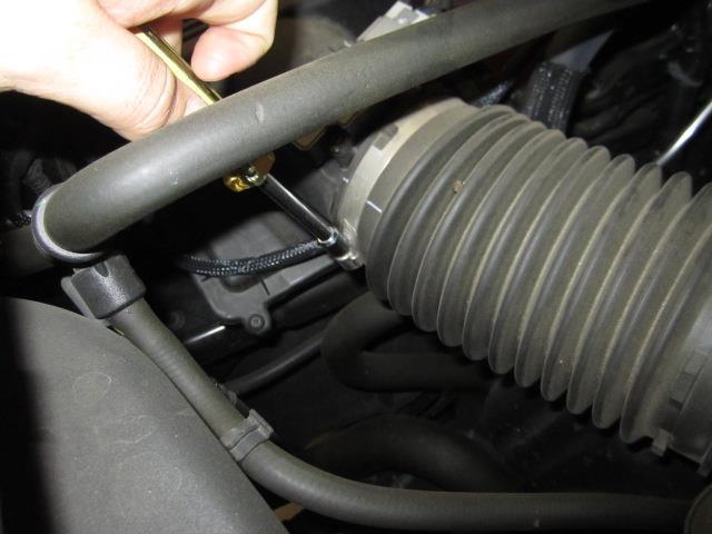
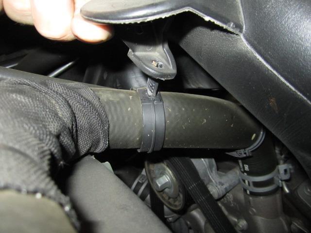
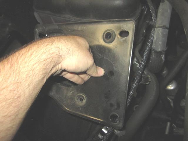
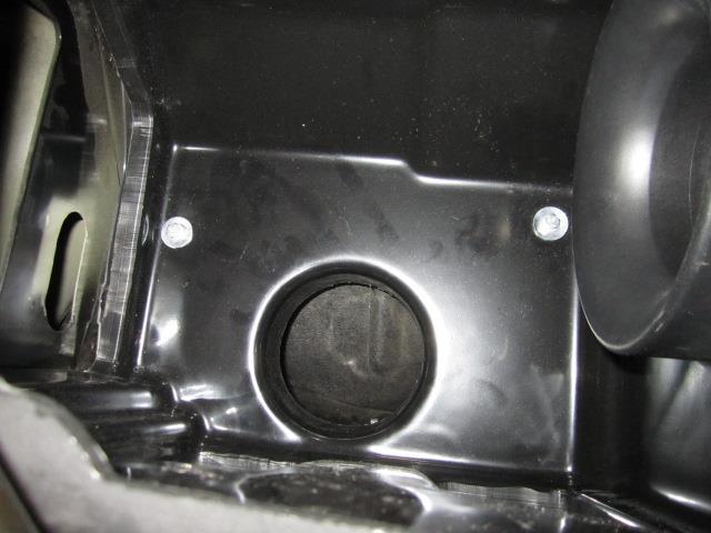
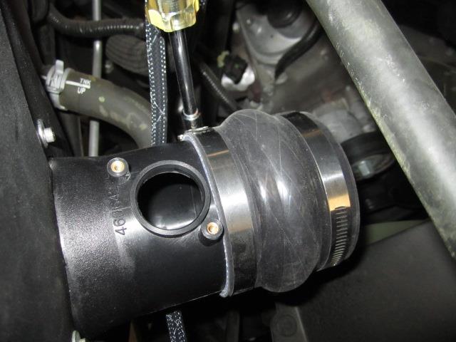
3 Installation Instructions: 1. Before you begin the install you must disconnect the negative battery cable. Failure to disconnect the battery may cause a check engine light or damage to your engine. (Fig A) 2. Remove the engine cover by pulling up and out. (Fig B) 3. Remove the breather hose from the resonator box by pulling straight out. (Fig C) 4. Loosen the clamp holding the duct to the throttle body using a 5/16 socket or nut driver. (Fig D) 5. Loosen the clamp holding the duct to the air box using a 5/16 socket or nut driver. (Fig E) 6. Remove the tree rivet holding the radiator hose to the air duct. (Fig F) 7. Lift up on the factory duct and remove it from the engine compartment. (Fig G) 8. Disconnect the MAF harness from the MAF sensor. (Fig H) 9. Disconnect the pressure sensor from the pressure sensor harness. (Fig I) 10. Lift up on the factory air box and remove it from the engine compartment. (Fig J) 11. Remove the 4-10mm bolts from the factory air box mounting tray. (Fig K) 12. Remove the factory air box mounting tray. (Fig L) 13. Remove the factory breather hose from the passenger's side valve cover. (Fig M) 14. Remove the pressure sensor from the factory air box. (Fig N) 15. Remove the MAF sensor from the factory air box. (Fig O) 16. Place the Volant box into the factory position. (Fig P) 17. Tighten the box in place using a 10mm wrench or socket and the 2-6mm x 25 bolts, 1/4 lock washers and 1/4 x 7/8 washers. (Fig Q) 18. Attach the 3 3/4 Hump hose to the MAF adapter using a #60 clamp with a 5/16 socket or nut driver only. (Fig R) 19. Press the supplied V-ring grommet onto the Volant duct. (Fig S) 3
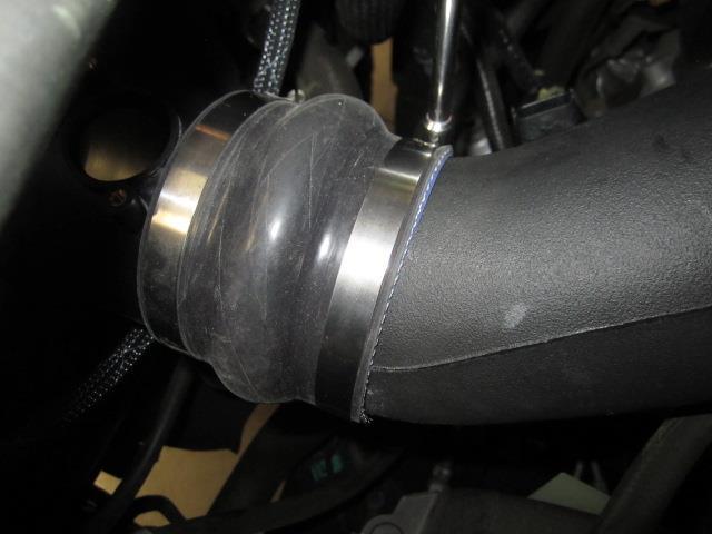
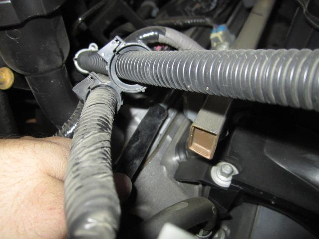
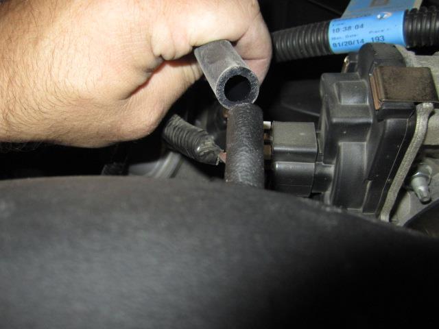
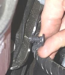
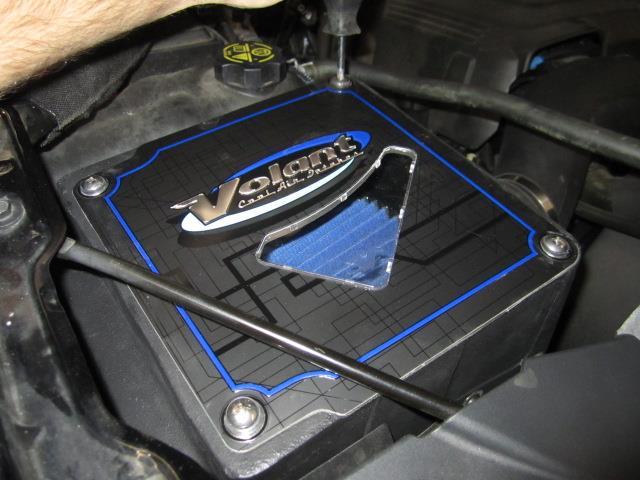
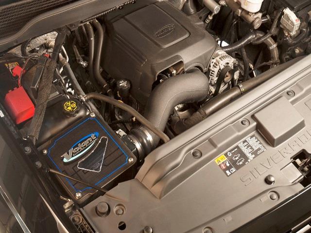
4 20. Attach the Pressure sensor onto the Volant duct with the provided 4mm x 16 screw. (Fig T) 21. Press the Volant duct into the 3 3/4 hump hose, do not tighten the clamp at this time. (Fig U) 22. Press the Volant duct onto the throttle body. (Fig V) 23. Tighten the duct to the throttle body using a 5/16 socket or nut driver only. (Fig W) 24. Tighten the clamp holding the duct to the hump hose using a 5/16 socket or nut driver only. (Fig X) 25. Tighten the MAF sensor onto the adapter using the provided 2-4mm x 12 screws. (Fig Y) 26. Attach the MAF sensor harness to the MAF sensor. (Fig Z) 27. It may be necessary to adjust the clamps holding the pressure sensor harness to the battery tray; it is possible to slide the clamps down the harness without removing them from the tray. (Fig AA) If needed, remove the Christmas Tree plugs. (See AA Inset Photo) 28. Attach the pressure sensor harness onto the sensor. (Fig BB) 29. Press the supplied breather hose onto the left side valve cover vent. No clamp is required. (Fig CC) 30. Press the breather hose onto the Volant duct. No clamp is required. (Fig DD) 31. Slide the 5119 filter into the Volant box and onto the adapter. (Fig EE) 32. Tighten the 5119 filter onto the adapter using a 5/16 socket or nut driver only. (Fig FF) 33. Remove the protective film from the lid and tighten to the box using the provided hardware. (Fig GG) 34. Reconnect the negative battery cable and check all connections before starting the vehicle, retighten all hardware after 100, 500 and 1000 miles of normal driving. (Fig HH) *Check that this air intake complies with your Federal, State and Local laws. We recommend saving your stock system. BEFORE ROAD TESTING 1. Start engine, leaving the transmission in park and securing the parking brake. 2. Make sure to look and listen for any unusual noises or air leaks. Repair problems if needed. 3. Once completed it will be necessary to check periodically, after a few heat cycles, for realignment and tightening of all connections. CARE AND CLEANING If using the Primo cotton reusable filter periodically and remove any excessive dirt build-up by tapping the filter on the ground and brushing off the loosened dirt. Clean the filter by using a two stage cleaning kit to thoroughly clean and reoil the filter. Re-oil every 10,000 miles without cleaning to improve filtering in sand and dirt. Clean only when dirt is very excessive or 50,000 miles. PICTURES ON NEXT PAGE 4


5 Fig. A Fig. B Fig. C Fig. D Fig. E Fig. F CONTINUED ON NEXT PAGE 5


6 Fig. G Fig. H Fig. I Fig. J Fig. K Fig. L CONTINUED ON NEXT PAGE 6


7 Fig. M Fig. N Fig. O Fig. P Fig. Q Fig. R CONTINUED ON NEXT PAGE 7


8 Fig. Fig. S S Fig. T Fig. U Fig. V Fig. W Fig. X CONTINUED ON NEXT PAGE 8


9 Fig. Y Fig. Z Fig. AA Fig. BB Fig. CC Fig. DD CONTINUED ON NEXT PAGE 9


10 Fig. EE Fig. FF Fig. GG Fig. HH 10
IMPORTANT WARRANTY & INSTALLATION INSTRUCTIONS ATTACHED
 IMPORTANT WARRANTY & INSTALLATION INSTRUCTIONS ATTACHED Please Forward All Attached Information to Consumer Warranty Not Valid Unless Returned to Volant Performance STOP Please take time to read and understand
IMPORTANT WARRANTY & INSTALLATION INSTRUCTIONS ATTACHED
 IMPORTANT WARRANTY & INSTALLATION INSTRUCTIONS ATTACHED Please Forward All Attached Information to Consumer Warranty Not Valid Unless Returned to Volant Performance STOP For Full-Color Installation Instructions,
IMPORTANT WARRANTY & INSTALLATION INSTRUCTIONS ATTACHED
 IMPORTANT WARRANTY & INSTALLATION INSTRUCTIONS ATTACHED Please Forward All Attached Information to Consumer Warranty Not Valid Unless Returned to Volant Performance For Full-Color Installation Instructions,
IMPORTANT WARRANTY & INSTALLATION INSTRUCTIONS ATTACHED
 IMPORTANT WARRANTY & INSTALLATION INSTRUCTIONS ATTACHED Please Forward All Attached Information to Consumer Warranty Not Valid Unless Returned to Volant Performance STOP For Full-Color Installation Instructions,
IMPORTANT WARRANTY & INSTALLATION INSTRUCTIONS ATTACHED
 IMPORTANT WARRANTY & INSTALLATION INSTRUCTIONS ATTACHED Please Forward All Attached Information to Consumer Warranty Not Valid Unless Returned to Volant Performance STOP Please be sure to review the enclosed
IMPORTANT WARRANTY & INSTALLATION INSTRUCTIONS ATTACHED
 IMPORTANT WARRANTY & INSTALLATION INSTRUCTIONS ATTACHED Please Forward All Attached Information to Consumer Warranty Not Valid Unless Returned to Volant Performance STOP Please be sure to review the enclosed
IMPORTANT WARRANTY & INSTALLATION INSTRUCTIONS ATTACHED
 IMPORTANT WARRANTY & INSTALLATION INSTRUCTIONS ATTACHED Please Forward All Attached Information to Consumer Warranty Not Valid Unless Returned to Volant Performance STOP For Full-Color Installation Instructions
IMPORTANT WARRANTY & INSTALLATION INSTRUCTIONS ATTACHED
 IMPORTANT WARRANTY & INSTALLATION INSTRUCTIONS ATTACHED Please Forward All Attached Information to Consumer Warranty Not Valid Unless Returned to Volant Performance For Full-Color Installation Instructions,
IMPORTANT WARRANTY & INSTALLATION INSTRUCTIONS ATTACHED
 IMPORTANT WARRANTY & INSTALLATION INSTRUCTIONS ATTACHED For Full-Color Installation Instructions, Please Visit: VOLANT.COM and Search by Part Number Please be sure to review the enclosed instructions prior
IMPORTANT WARRANTY & INSTALLATION INSTRUCTIONS ATTACHED
 IMPORTANT WARRANTY & INSTALLATION INSTRUCTIONS ATTACHED Please Forward All Attached Information to Consumer Warranty Not Valid Unless Returned to Volant Performance Please be sure to review the enclosed
IMPORTANT WARRANTY & INSTALLATION INSTRUCTIONS ATTACHED
 IMPORTANT WARRANTY & INSTALLATION INSTRUCTIONS ATTACHED For Full-Color Installation Instructions, Please Visit: VOLANT.COM and Search by Part Number Please be sure to review the enclosed instructions prior
IMPORTANT INSTALLATION INSTRUCTIONS ATTACHED
 IMPORTANT INSTALLATION INSTRUCTIONS ATTACHED For Full-Color Installation Instructions, Please Visit: VOLANT.COM and Search by Part Number Please be sure to review the enclosed instructions prior to beginning
IMPORTANT WARRANTY & INSTALLATION INSTRUCTIONS ATTACHED
 IMPORTANT WARRANTY & INSTALLATION INSTRUCTIONS ATTACHED Please Forward All Attached Information to Consumer Warranty Not Valid Unless Returned to Volant Performance STOP For Full-Color Installation Instructions,
IMPORTANT WARRANTY & INSTALLATION INSTRUCTIONS ATTACHED
 IMPORTANT WARRANTY & INSTALLATION INSTRUCTIONS ATTACHED Please Forward All Attached Information to Consumer Warranty Not Valid Unless Returned to CORSA Performance We ask that you take a few moments to
Recommended Tools: 5/16 nut driver or socket 11mm nut driver or socket Flathead Screwdriver
 Please take time to read and understand these installation instructions. CORSA recommends that the installation of this system be performed by a qualified service center or professional installer who has
IMPORTANT WARRANTY & INSTALLATION INSTRUCTIONS ATTACHED
 IMPORTANT WARRANTY & INSTALLATION INSTRUCTIONS ATTACHED Please Forward All Attached Information to Consumer Warranty Not Valid Unless Returned to Volant Performance STOP Please be sure to review the enclosed
INSTALLATION INSTRUCTIONS Unitronic Intercooler Upgrade Kit for 2.0 TSI Gen3 MQB UH009-ICA
 Unitronic recommends that you read through the entire installation instructions prior to beginning the installation to familiarize yourself with the included components, tools required, and procedures
Fig A. ADDICTIVE DESERT DESIGNS Preparation: Installation:
 Preparation: Disconnect the negative battery terminal. Park the vehicle on level ground and set the emergency brake. We recommend reading through the installation instructions in whole before performing
MODULAR BUMPER INSTALLATION MANUAL
 MODULAR BUMPER INSTALLATION MANUAL Parts List* 1 Center section 1 Side extension, passenger / right 1 Side extension, driver / left 1 Side cap, passenger / right 1 Side cap, driver / left 1 Brush guard,
PRODUCT: TJ Corner Guards READ INSTRUCTIONS IN FULL BEFORE INSTALLATION. QUESTIONS? CALL M-F 7:00 AM 5:00 PM PST
 PRODUCT: TJ Corner Guards READ INSTRUCTIONS IN FULL BEFORE INSTALLATION. QUESTIONS? CALL 916-631-8071 M-F 7:00 AM 5:00 PM PST The MetalCloak experience includes the ease of installation of our products.
INSTALLATION MANUAL FRONT. See pages 2 and 3 of this manual for configuration options. Level of Difficulty. Product Photo (center section only)
") INSTALLATION MANUAL FRONT Level of Difficulty Moderate Product Photo (center section only) All hardware listed below will be provided with the bumpers center section. Additional hardware will be supplied
INSTALLATION MANUAL FRONT Level of Difficulty Moderate Product Photo (center section only) All hardware listed below will be provided with the bumpers center section. Additional hardware will be supplied
To install new top weight plate bushings in G7 strength units.
 1/5 PURPOSE To install new top weight plate bushings in G7 strength units. RE-WORK PARTS REQUIRED - ZMS4000424 Top Weight Plate Bushing (Quantity 4 per machine). - Matrix Top Weight Plate Bushing Removal
Medium HoneyBadger Chase Rack Installation Instructions
 PREPARATION Medium HoneyBadger Chase Rack Installation Instructions 1. Disconnect the negative terminal on the battery. Park the vehicle on level ground and set the emergency brake. 2. We recommend reading
SAFETY THIS PRODUCT IS FOR OFFROAD USE ONLY. ALL LIABILITY FOR INSTALLATION AND USE RESTS WITH THE OWNER.
 SAFETY Your safety and the safety of others is very important. In order to help you make informed decisions about safety, we have provided installation instructions and other information. These instructions
2012+ F30 320i, 328i F22 228i Carbon Fiber S-FLO Intake INSTALLATION GUIDE FOR RACING USE ONLY
 PERFORMNCE ENGINEERING FOR EUROPEN UTOS INSTLLTION GUIDE 2012+ F30 320i, 328i 2014+ F22 228i Carbon Fiber S-FLO Intake FOR RCING USE ONLY Congratulations on your purchase of the WE Tuning Carbon Fiber
Please read BOTH these Installation Instructions and the General Towing Instructions before attempting to install or operate this equipment.
 2005-08 Pontiac G6 GT Please read BOTH these and the General Towing Instructions before attempting to install or operate this equipment. 1. Blue Ox towing products and accessories are intended to be installed
PROVEN WORLDWIDE SNORKEL FOR CHEVY COLORADO NEW PRODUCT
 AEV30272AC Last Updated: 10/09/18 PROVEN WORLDWIDE SNORKEL FOR CHEVY COLORADO NEW PRODUCT Please visit www.aev-conversions.com to view the most current installation guide for this product. This is a new
FENDER FLARE INSTALLATION
 Customer Support TM FENDER FLARE INSTALLATION TG-FF8C4108 IMPORTANT TYGER only approves the installation according to our instructions with the hardware provided. WARNING Failure to complete the installation
SAFETY THIS PRODUCT IS FOR OFFROAD USE ONLY. ALL LIABILITY FOR INSTALLATION AND USE RESTS WITH THE OWNER.
 SAFETY Your safety and the safety of others is very important. In order to help you make informed decisions about safety, we have provided installation instructions and other information. These instructions
Installation Instructions Jeep JL Front Grumper Product Number: GR4600 Application: 18+ JEEP JL
 ! IMPORTANT SAFETY GUIDE Your safety and the safety of others is very important. In order to help you make informed decisions about safety, we have provided the following warnings, safety precautions,
INSTALLATION INSTRUCTIONS
 Do not attempt to install this product on any vehicle other than the one it is designed for and listed above! Parts List 10 3/8 X 1 1/4 Hex Bolt 10 3/8 Lock Washer 4 3/8 Hex Nut 4 3/8 Flat Washer 2 3169)
BX2173 Installation Instructions Ford Focus (including the 2.3L engine) 2003 Ford Focus SVT
 2003 Ford Focus SVT") BX2173 Installation Instructions 2000-04 Ford Focus (including the 2.3L engine) 2003 Ford Focus SVT Serial No. The front fascia, coolant line bracket and anti-pollution devices are removed for baseplate
BX2173 Installation Instructions 2000-04 Ford Focus (including the 2.3L engine) 2003 Ford Focus SVT Serial No. The front fascia, coolant line bracket and anti-pollution devices are removed for baseplate
INSTRUCTIONS. INTERCOOLER UPGRADE BMW E82 135i 2008-
 INSTRUCTIONS INTERCOOLER UPGRADE BMW E82 135i 2008- Parts Included: - Intercooler - 4 door shield - 2-45 degree Silicone Hoses ( 2.5 x 3 ) - 1 2.5x3 silicone straight hose. - 1 45 degree aluminum pipe
Dorian Triple and Quad Instructions Installation Instructions
 Installation Instructions www.ergomart.com 888 40 00 STEP UNPACKING... Page STEP COLUMN... Page 7 STEP MOUNTS Free Standing Base... Page 4 Clamp Mount... Page 5 Thru Mount... Page 6 STEP 4 WORK SURFACE...
Installation Instructions Precision Sport Shifter
 Installation Instructions Precision Sport Shifter 2004 and up Pontiac GTO Part Number 45043 2010, 2005, 2004 by B&M Racing and Performance Products This B&M Precision Sport Shifter has been designed to
X 12 SOLARIUM ASSEMBLY INSTRUCTIONS Two or more adults required for assembly
 adlonco@hotmail.com 1212-12 12 X 12 SOLARIUM ASSEMBLY INSTRUCTIONS Two or more adults required for assembly Base Dimensions 12 ½ x12 ½, Largest Dimensions 13 6 x13 6 (see pg.1) Overall Height 110 ZZZ-182.1212-12.1030-15.GP.EN.HER
SAFETY THIS PRODUCT IS FOR OFFROAD USE ONLY. ALL LIABILITY FOR INSTALLATION AND USE RESTS WITH THE OWNER.
 SAFETY Your safety and the safety of others is very important. In order to help you make informed decisions about safety, we have provided installation instructions and other information. These instructions
2017 Current Ford Raptor ADD Pro Front Bumper Installation Instructions
 2017 Current Ford Raptor ADD Pro Front Bumper Installation Instructions PREPARATION 1. Disconnect the negative terminal on the battery. Park the vehicle on level ground and set the emergency brake. 2.
FLAT PANEL CART WITH OR WITHOUT A PULL OUT SHELF
 FP42UL FP60UL FP42MUL FP60MUL FLAT PANEL CART WITH OR WITHOUT A PULL OUT SHELF WARNING: FP42 carts are intended to hold monitors up to 75 lbs and FP60 carts are intended to hold monitors up to 100 lbs.
Fig A ADDICTIVE DESERT DESIGNS. Preparation: Removal:
 Preparation: Disconnect the negative battery terminal. Park the vehicle on level ground and set the emergency brake. We recommend reading through the installation instructions in whole before performing
Please read BOTH these Installation Instructions and the General Instructions prior to installing or operating this equipment.
 Attachment Tab Height: 16-1/2 Serial Number Attachment Tab Width: 24 Please read BOTH these and the General Instructions prior to installing or operating this equipment. 1. Blue Ox towing products and
STRAIGHT HANDLEBAR KIT
 STRAIGHT HANDLEBAR KIT P/N 2881973 APPLICATION All straight bar applications, excluding 550 Indy and Voyageur models BEFORE YOU BEGIN Read these instructions and check to be sure all parts and tools are
2015 Current Ford F150/Raptor Adaptive Cruise Control Module Relocation Bracket Installation Instructions
 2015 Current Ford F150/Raptor Adaptive Cruise Control Module Relocation Bracket Installation Instructions PREPARATION 1. Disconnect the negative terminal on the battery. Park the vehicle on level ground
Rugged Ridge Front Bumper Winch Plate JK
 Rugged Ridge Front Bumper Winch Plate 13-17 JK Note: These instructions involve cutting parts of your vehicle. Please read all instructions prior to starting. Installation Time: 2-3 Hours Tools Required:
HANDLEBAR KIT P/N APPLICATION BEFORE YOU BEGIN KIT CONTENTS TOOLS REQUIRED. Instr Rev Page 1 of 6
 HANDLEBAR KIT P/N 2881993 APPLICATION All straight bar applications, excluding 550 Indy and Voyageur models BEFORE YOU BEGIN Read these instructions and check to be sure all parts and tools are accounted
BX1965 Installation Instructions 2004 Chrysler Sebring Convertible
 BX1965 Installation Instructions 2004 Chrysler Sebring Convertible Serial No. The headlight assembly, front fascia, horn bracket and windshield washer reservoir are removed for baseplate installation.
Barricade Trail Force HD Rear Bumper w/ Tire Carrier installation (07-16 Wrangler JK)
") Barricade Trail Force HD Rear Bumper w/ Tire Carrier installation (07-16 Wrangler JK) Installation Time: 2-3 Hours Tools Required: Tire iron Ratcheting socket set (ratchet plus 13, 16, 19mm sockets) Open
Barricade Trail Force HD Rear Bumper w/ Tire Carrier installation (07-16 Wrangler JK) Installation Time: 2-3 Hours Tools Required: Tire iron Ratcheting socket set (ratchet plus 13, 16, 19mm sockets) Open
WARNING Honda Pilot Installation Instructions BX2244. Serial Number
 Please read BOTH these and the General Instructions before attempting to install or operate this equipment. Serial Number 1. Blue Ox towing products and accessories are intended to be installed by Blue
12 X 18 SOLARIUM ASSEMBLY INSTRUCTIONS
 adlonco@hotmail.com 1218 12 X 18 SOLARIUM ASSEMBLY INSTRUCTIONS Assembly by more than one person is recommended. Base Dimensions 12 ½ x18 11, Largest Dimensions 13 6 x20 ½ (see pg.1) ZZZ-18.1218.0530-1.GP.EN.HER.doc
**MOUNTING YOUR MONITOR
 FPP72V200 72 FREE STANDING DISPLAY CART Assembly Instructions Hardware List Ref. Qty. Part No. Description AA 4 030-1128 1/4-20 UNC, 1 3/4 Socket Hd Screws BB 1 030-1129 5/8-11 UNC 1 3/4 Socket Hd Screw
12 X 15 SOLARIUM ASSEMBLY INSTRUCTIONS
 115 1 X 15 SOLARIUM ASSEMBLY INSTRUCTIONS Assembly by more than one person is recommended. Base Dimensions 1 ½ x15 6, Largest Dimensions 13 6 x16 11 (see pg.13) L:\WP51\Instructions\SOLARIUMS INSTRUCTION
Elite Series Fender Flares
 Page 1 of 8 Installation Instructions I - Sheet Number I606RPG Rev.B Important Safety Information Tools Required Contents Elite Series Fender Flares Preparation Before Painting / Installation NOTE Actual
SEAT-361 E-Z-Go RXV RHOX Seat Kit Installation Instructions
 SEAT-361 E-Z-Go RXV RHOX Seat Kit Installation Instructions Contents of SEAT-361 RHOX 300 Series Rear Seat Kit: a (1 ea.) Front Seat Back Support, Driver Side b (1 ea.) Front Seat Back Support, Passenger
Installation Guide for Rough Country 1.25 inch Body Lift Kit w/o Shocks (07-15 Wrangler JK 4 Door) Item # J10048 Option B; Manual
 Item # J10048 Option B; Manual") Installation Guide for Rough Country 1.25 inch Body Lift Kit w/o Shocks (07-15 Wrangler JK 4 Door) Item # J10048 Option B; Manual Installation Time: 3 Hours Tools Required: Jack (Tall enough to reach body
Installation Guide for Rough Country 1.25 inch Body Lift Kit w/o Shocks (07-15 Wrangler JK 4 Door) Item # J10048 Option B; Manual Installation Time: 3 Hours Tools Required: Jack (Tall enough to reach body
55000/55010 Installation Instructions
 A. Install 55015 B. Bolt roof rails, 55020/55025, to front hoop. C. Assemble 55026 D. To install without drilling into bumper. E. If mounting directly to bumper. A. 55015 Installation Instructions 55000/55010
Please read BOTH these Installation Instructions and the General Instructions prior to installing or operating this equipment.
 Attachment Tab Height: 13 Attachment Tab Width: 24 Please read BOTH these and the General Instructions prior to installing or operating this equipment. Serial Number 1. Blue Ox towing products and accessories
INSTALLATION INSTRUCTIONS KK-K9-C12-K CHEVY IMPALA
 INSTALLATION INSTRUCTIONS KK-K9-C12-K 2000-2005 CHEVY IMPALA READ ALL INSTRUCTIONS PRIOR TO INSTALLATION TOOLS REQUIRED: Power Drill Drill bits1/4 and 5/32 7/l6 wrench and socket 15,18 and\or 19mm socket
2016 Current Toyota Tacoma HoneyBadger Front Bumper Installation Instructions
 2016 Current Toyota Tacoma HoneyBadger Front Bumper Installation Instructions PREPARATION 1. Disconnect the negative terminal on the battery. Park the vehicle on level ground and set the emergency brake.
SAFETY SENSORS FIELD OF VIEW WILL BE ALTERED WITH USE OF THE REPLACEMENT BUMPER. Injury hazard
 SAFETY Your safety and the safety of others is very important. In order to help you make informed decisions about safety, we have provided installation instructions and other information. These instructions
Bi-Color Signal Mirror Installation Instructions
 Bi-Color Signal Mirror Installation Instructions 2005-2009 Toyota Tacoma THE safety accessory of the 21 st Century. P/N 210-0141-0 Rev. A2 (3/30/09), BTV 2007 Muth Mirror Systems, LLC Page 3 of 13PplPage
STEP 1 : DESTROYER FRONT BUMPER INSTALL GATHER YOUR TOOLS AND LAY OUT YOUR PARTS... *shorty bumper to show hardware* Tools Required:
 DESTROYER FRONT BUMPER INSTALL JL STEP 1 : GATHER YOUR TOOLS AND LAY OUT YOUR PARTS... Tools Required: - Utility knife - 11/16 Deep socket - Ratchet - 11/16 Crescent wrench - Ratchet Extension - 1/4 socket
WARNING. Bolt Torque Specifications Torque in Foot-Pounds for Inch Bolts Bolt Size Grade 5 Grade 8
 1. Blue Ox towing products and accessories are intended to be installed by Blue Ox Dealers who are familiar with our products and have the equipment and knowledge necessary to do fit work. If needed, Blue
JARVIS. Model Brisket Scissor EQUIPMENT... TABLE OF
 Model 423-17 Brisket Scissor EQUIPMENT SELECTION... Ordering No. TABLE OF CONTENTS... Page Model 423--17... 4037003 Air Filter / Regulator / Lubricator 3022003 Air Hose Assembly... 3059018 Balancer...
1. Remove factory stock bump stop and mount from the frame.
 1. Disconnect the negative terminal on the battery. With the vehicle on level ground and the emergency brake set, block the front tires. 2. Jack up the rear of the vehicle and support the frame rails with
SAFETY THIS PRODUCT IS FOR OFFROAD USE ONLY. ALL LIABILITY FOR INSTALLATION AND USE RESTS WITH THE OWNER.
 SAFETY Your safety and the safety of others is very important. In order to help you make informed decisions about safety, we have provided installation instructions and other information. These instructions
2010+ Dodge Ram 2500/3500 Front Bumper Install Instructions
 2010+ Dodge Ram 2500/3500 Front Bumper Install Instructions Warning! Read the instructions completely before beginning the installation. Before tightening bolts, drilling or cutting where required, check
Assembly Instructions BBQ400
 Assembly Instructions BBQ400 DOC035 REV C PARTS LIST PART PREVIEW DESCRIPTION QTY PART# ID# 1/4-20 SHOULDER BOLT LONG 4 HDW154 A WASHER 1/2OD X 1/4 ID FLAT ZINC 38 HDW072 B TOP SECTION 1 C 1/4-20 x.625
AM33 LP-P Natural Gas Conversion Manual For Outdoor Use Only
 AM33 LP-P Natural Gas Conversion Manual For Outdoor Use Only 1 4 6 2 3 5 Part No. Qty Description 1 RCOZZ00339A 1 Main Burner Valve & Manifold Assembly with Valves (NG) 2 RCOZZ00340A 1 Side Burner Assembly
BOX-117 E-Z-Go RXV Utility Box Mounting Kit Installation Instructions
 BOX-117 E-Z-Go RXV Utility Box Mounting Kit Installation Instructions Contents of BOX-117 Utility Box Mounting Kit: a (1 ea.) Utility Box Support Frame, Driver Side b (1 ea.) Utility Box Support Frame,
FENDER FLARE INSTALLATION
 Part#: TG-FF8G4158 FOR 2007-2013 GMC Sierra 1500 Pickup Truck (Exclude 69.3inch Short Bed Models) FENDER FLARE INSTALLATION Hardware Kit Included IMPORTANT TYGER only approves the installation according
Signal Mirror Installation Instructions Toyota Tacoma
 Signal Mirror Installation Instructions 2005-2015 Toyota Tacoma THE safety accessory of the 21 st Century. P/N 210-0115-0 Rev. A4 (3/11/15), BTV 2005 Muth Mirror Systems, LLC Page 3 of 12PplPage 3 of 12
- INSTALLATION INSTRUCTIONS -
 . Supercharger Shaft Upgrade Kit PART# - RY17040-UK-6S5-2 APPLICATION(S): Yamaha FX-SHO, FZR & FZS Required tools Part# IN LB Electronic Torque Wrench N/A T-30 Torx Bit Socket N/A 3mm Allen Wrench N/A
JK FRONT FENDER FLARE INSTALLATION INSTRUCTIONS
 JK FRONT FENDER FLARE INSTALLATION INSTRUCTIONS TOOLS NEEDED 3/16 Allen Wrench 1/2 Socket or wrench 10mm Socket Flat head screwdriver HARDWARE 5/16 x 3/4 button heads (14) 5/16 x 1 button heads (8) 5/16
ADDICTIVE DESERT DESIGNS
 Preparation: Disconnect the negative battery terminal. Park the vehicle on level ground and set the emergency brake. We recommend reading through the installation instructions in whole before performing
x12 GAZEBO ASSEMBLY INSTRUCTIONS
 adlonco@hotmail.com 30 10 x1 GAZEBO ASSEMBLY INSTRUCTIONS Assembly with more than one person recommended 0 ZZZ-0.30.100-1.GP.EN.HER.doc Before you assemble the Gazebo It is important that this gazebo be
BMW E39/E53 Android Touch Screen Radio Installation Instructions
 BMW E9/E5 Android Touch Screen Radio Installation Instructions Enjoy your new Android Radio from Bremmen Parts, we appreciate your business. Vibrant Touch Display This radio features a responsive 9 touch
* * APPLICABLE MODELS: 2014 > MAZDA 3
 PART NUMBER: 0000 8C L46 GENUINE ACCESSORIES INSTALLATION INSTRUCTIONS Rev. AAA *550-0604-000* APPLICABLE MODELS: 204 > MAZDA 3 REQUIRED COMPONENTS: ITEM QTY DESCRIPTION Usage Chart MIRROR ASSEMBLY: Mirror
Signal Mirror Installation Instructions Dodge Charger, Dodge Magnum, Chrysler 300
 Signal Mirror Installation Instructions 2006-2009 Dodge Charger, 2005-2008 Dodge Magnum, 2005-2009 Chrysler 300 THE safety accessory of the 21st Century. P/N 210-0123-0 Rev. A4 (10/7/09), BTV 2007 Muth
RUN-IN SHED INSTRUCTIONS
 RUN-IN SHED INSTRUCTIONS 14321 5th Line Nassagaweya, Rockwood, ON, N0B 2K0 Phone 519-856-9959 ~ Fax 519-856-4141 Toll Free 1-800-461-3362 ~ Email sales@systemhorse.com Website www.systemfence.com RUN-IN
TOYOTA COROLLA EC REARVIEW MIRROR Section I Installation Preparation
 Section I Installation Preparation Part Number: PT374-02030 Section I Installation Preparation Kit Contents Item # Quantity Reqd. Description 1 1 AD Mirror Assembly w/compass & Maplights 2 1 Hardware Bag
BOX-115 Club Car Precedent Utility Box Mounting Kit Installation Instructions
 BOX-115 Club Car Precedent Utility Box Mounting Kit Installation Instructions Contents of BOX-115 Utility Box Mounting Kit: a (1 ea.) Utility Box Support Frame, Passenger Side b (1 ea.) Utility Box Support
- 1 - P/N REV E 9/15
 INSTRUCTIONS HIGH TECH II DELUXE FLUSH UNIT ASSEMBLY The following instruction is a guideline, illustrating suggested methods, assembly sequence, and tool selection. Actual assembly may vary by each situation.
SUT-1000CLC ASSEMBLY REQUIREMENTS
 SUT-1000CLC Torque wrench, carpenters square, wire cutters, Phillips screwdriver, 7/16, 9/16, and 3/4 combination wrenches, ratchet, 9/16, 3/4, 13/16, and 7/8 sockets. ASSEMBLY REQUIREMENTS *Torque all
FENDER FLARE INSTALLATION
 TG-FF8T4178: Fit 2014-UP Toyota Tundra PRIOR TO INSTALLATION IMPORTANT Tyger only approves the installation according to our instructions with the hardware provided. WARNING Failure to complete the installation
Signal Mirror Installation Instructions
 Signal Mirror Installation Instructions 2005-2010 Chevy Corvette C6 THE safety accessory of the 21 st Century. P/N 210-0144-0 Rev. A3 (9/29/2011), BTV 2007 Muth Mirror Systems, LLC Page 3 of 10PplPage
ASSEMBLY INSTRUCTIONS 10 X14 HIGGINS HARDTOP GAZEBO ITEM# L-GZ212PST-4
 3811110 ASSEMBLY INSTRUCTIONS 10 X14 HIGGINS HARDTOP GAZEBO ITEM# L-GZ212PST-4 Parts List Square pole A 4 Round pole B 4 Short arch bar C 4 Long arch bar D 6 Long beam 1 E1 2 Long beam 2 E2 2 Long beam
All Terrain Flares 2014 Chevy Silverado
 Page 1/8 Components: 1. Front Flares (2) 2. Rear Flares (2) Tools required: - Utility knife - #2 Phillips driver - Socket wrench - 13 mm Socket - 6 mm Allen Wrench - T-15 Torx bit - Trim Removal Tool -
Rugged Ridge Engine Transmission Skid Plate JK
 Installation Time: 1-2 Hours Tools Required: Rugged Ridge Engine Transmission Skid Plate 2012-2017 JK Sockets: 16mm, 17mm, 18mm deep well Socket Wrench Wrenches: 16mm, 18mm Torque Wrench Drill ½ Drill
FRONT BUMPER KIT P/N APPLICATION BEFORE YOU BEGIN KIT CONTENTS. Instr Rev Page 1 of 6
 FRONT BUMPER KIT P/N 2882301 APPLICATION Verify accessory fitment at Polaris.com. BEFORE YOU BEGIN Read these instructions and check to be sure all parts and tools are accounted for. Please retain these
TABLE OF CONTENTS DRAWINGS
 TABLE OF CONTENTS Bifold Door Adjustment Procedures...pg 4 Bifold Door Maintenance...pg 6 Safety Concerns...pg 9 Troubleshooting...pg 10 Bifold Door Maintenance Checklist...pg 11 DRAWINGS EK 1880 Bifold
SAM. Model: STV-C65 LCD Mobile Visualized Stand Instruction Manual. Weight Capacity: 1251bs / 56.7kg Suits LCD Flat Panel Display: 42"-55" Page 20
 SAM Model: STV-C65 LCD Mobile Visualized Stand Instruction Manual Weight Capacity: 1251bs / 56.7kg Suits LCD Flat Panel Display: 42"-55" 20 Step 6 LCD Mobile Lift Stand Model: STV-C65 Cable management
TOYOTA TACOMA TRAILER WIRE HARNESS Preparation
 Preparation Part Number: PT725-35120 Kit Contents Item Quantity Reqd. Description # 1 1 Flasher Assembly (F/A) 2 1 Wire Harness 3 1 Sub Wire Harness 4 2 Plastic Tie (300mm) 5 4 Plastic Tie (200mm) 6 13
Chrome Mustang Billet Interior Door Handles (05-09) - Installation Instructions
 - Installation Instructions") Chrome Mustang Billet Interior Door Handles (05-09) - Installation Instructions The below installation instructions work for the following products: Chrome Mustang Billet Interior Door Handles (05-09)
Chrome Mustang Billet Interior Door Handles (05-09) - Installation Instructions The below installation instructions work for the following products: Chrome Mustang Billet Interior Door Handles (05-09)
GENUINE ACCESSORIES INSTALLATION INSTRUCTIONS. ITEM QTY DESCRIPTION Usage Chart
 PART NUMBER: 0000 8C R0 GENUINE ACCESSORIES INSTALLATION INSTRUCTIONS Rev. AAA *550-0554-000* APPLICABLE MODELS: 203 > CX-5 REQUIRED COMPONENTS: ITEM QTY DESCRIPTION Usage Chart MIRROR ASSEMBLY: Mirror
H2-50 Hydrogen Generator Field Update
 This field update is intended to provide extra protection in the event the H2 generation cell fractures or cracks. Please add the additional parts to your H2-50 as soon as possible. Please take a digital
EMO. Service Instruction. created by Frank Weithöner. Table of contents: Special Tools Assembling Mixing Chamber
 EMO Service Instruction created by Frank Weithöner Table of contents: - Special Tools Disassembling Mixing Chamber Assembling Mixing Chamber Adjustment Rotor / Level Indicator Unit Temperature Compensating
x16 GAZEBO ASSEMBLY INSTRUCTIONS
 adlonco@hotmail.com 36-3 1 x16 GAZEBO ASSEMBLY INSTRUCTIONS Two or more adults required for assembly 0 ZZZ-05.36-3.117-15.GP.EN.HER.doc Before you assemble the Gazebo It is important that this gazebo be
N. 15th Street, Middlesboro, KY FLIP TARP DUMP BODY INSTALLATION INSTRUCTIONS
 1-800-248-7717 1002 N. 15th Street, Middlesboro, KY 40965 FLIP TARP DUMP BODY INSTALLATION INSTRUCTIONS Congratulations on your purchase of a Mountain Flip Tarp Dump Body tarping system. With tarping systems
WARNING. BX Ford Explorer With Adaptive Cruise Control & Eco Boost Installation Instructions
 Please read BOTH these and the General Instructions before attempting to install or operate this equipment. 1. Blue Ox towing products and accessories are intended to be installed by Blue Ox Dealers who
Signal Mirror Installation Instructions
 Signal Mirror Installation Instructions Ford Explorer 1996-2001, Ford Explorer SportTrac 2001, Ford Ranger 1996-2001, Mazda B-2500\B-3000\B-4000 1998-2001, Mercury Mountaineer 1997-2001 THE safety accessory