Mold Assembly and Machine Settings for Models, 22HF, 16HF, and 1600
|
|
|
- Chester Elliott
- 6 years ago
- Views:
Transcription


1 Knowledge Base Article Type: Instructions Mold Assembly and Machine Settings for Models, 22HF, 16HF, and 1600 Description: Instructions on How to properly assemble, clean and inspect, repair and rework molds, and proper mold care. WARNING Never work on, clean or service this unit, control panel or any machine or open or remove any protective cover, guard, grate, door, or maintenance panel until the power or energy sources has been turned off, locked out / tagged out, and all moving parts have come to a complete stop and or blocked to prevent movement. Machinery is dangerous avoid personal injury and or death by following manufacture, Local, and OHSA safety procedures. Contact Columbia Machine for safety decals, guards, horns and beacons.

2 Columbia recommends a sturdy table with a removable top plate, which can be reground as the surface deteriorates due to wear. Columbia part number (assembly table & surface height gauge-vernier calipers) 0
3 Recommended Tools cont. 4 Steel Wedges (for usage see page 28) Brass Hammer (Soft headed) Vernier Dial Calipers-Surface height gauge (for usage see page 29) 10 Machinist Square (for usage see page 32) Torque Wrench (range to 500 foot-pounds) Miscellaneous Wrenches appropriate for each bolt size (socket head, hex head, flat head capscrews) Replacement supply of grade5 & grade8 bolts, nuts, nylon insert locknuts, lockwashers, setscrews, (see Mold Torque Specifications Sheets) Thread locking compound, such as Loctite #262 to be used on torqued bolts 1
4 Regular Mold Care After production, thoroughly clean all mold wear surfaces of any concrete materials and apply oil to the wear parts prior to storage. (Cement is a caustic that can deteriorate even hardened steel) Coating the wear parts with oil before storage will protect their hardened wear surface from oxidation and pitting. A cause of premature mold life. Inspect parts for cracks and/or wear and replace before storage. 2
5 Mold Repair and Rework Welding Mold Wear Parts Insure good heat isolation to surrounding area Surface Hardness is effected at temperature starting at 250 degrees Immersion in water repeated small incremental welds with quenching to cool between each step Welding rod recommendation: Low Hydrogen based welding rod for general welding E4130 (rod used for welding SAE 4130 type Tool Steel) For small spot repairs Hard surfacing rod Welding Non Wear Surfaces Low Hydrogen based welding rod For welding Corebar Clips onto Corebar Assemblys For Welding Cores onto Corebar Assemblies General welding and patching Cores should be welded to Corebar (T-1 Spring steel) using 4 passes, 2 per side of the corebar, starting from outside edge of core and stopping at the middle of the core. Drill and Tap Rework Non wear parts can be reworked in a typical manner for mild steel Hardened wear parts have same characteristics as tools used to drill and tap, requiring carbide tools Soften area utilizing heat and then slow cooling Note: This will reduce mold wear life Grind through case in area to be reworked 3
6 Clean and inspect all parts prior to assembling mold. Check for excessive wear on all surfaces, including gouges and scored surfaces (0.025 depth or greater, consider replacement). Radiused edges on the bottom (pallet side) of end liners, partition plates, cores, etc., cause feathered edges on the pallet side of the block. Tip: Outside partition plates can be rotated 180 degrees. Check tapped holes for clean complete threads. 4


7 Clean and inspect all parts prior to assembling mold. cont. Mounting Bracket Die Support mounting surfaces should be clean, flat, free of paint or foreign material, and parallel. Mounting holes should not be elongated or cracked. Tip: Also check condition of the machine die supports. The mating surfaces should be flat, parallel, and square. 5

.")
8 Clean and inspect all parts prior to assembling mold. cont. Compression shoes should be flat and straight and have clean sharp edges (rounded edges will create feathered edges on the tops of the product). Tip: In Most Cases, Shoes can be flipped 180 degrees for added wear life. 6
 should")
9 Clean and inspect all parts prior to assembling mold. cont. Head plunger legs should be straight and the bottom (shoe side) should be flat. 7


10 Inspect the Corebar Assembly bottomside with a straightedge to insure bottoms are straight and flat. Check plunger pin to see that it operates smoothly and there is nothing interfering with venting while producing block. Clean and inspect all parts prior to assembling mold. cont. Columbia Plunger pin part no Check for wear on the plunger pin - That the vent hole is closed when the pin is flush with the bottom of the core. Columbia spring part no
11 Torque Specifications Torque specifications are for comparative purposes only. All bolts of similar size and function should be tightened to the same torque. Hex and socket head capscrews used should be SAE grade 8 (or metric equivalent) on the mold box and shoes, SAE grade 5 (or metric equivalent) or better on corebar assemblies and head plungers. Because the mold assembly vibrates during operation, even properly torqued bolts can loosen and regular checking to insure proper tightness is recommended. Columbia encourages using a thread-locking compound, such as Loctite #262 on torqued bolts. 9
 partition plates into the end plate notches.")
12 Lift one of the end plates, and position the first partition plate. Sliding one end of the interior (inside) partition plates into the end plate notches. Mold Box Assembly Optional aid is to use spacer blocks- 1 high spacers for 8-high molds. 3/8 spacers for 4-high molds. 10
 partition plates to the left and right sides of the end plates and the mounting brackets.")
13 Position the remaining end plate on the opposite end of the inside partition plates. Locate the drilled (outside) partition plates to the left and right sides of the end plates and the mounting brackets. Securing with one bolt at each corner of the box. Mold Box Assembly 11

14 Set the end liners into the cavities and install all fasteners using locktite thread locking compound. Use high collar lock washers to ensure correct thread depth. Mold Box Assembly 12

15 Mold Box Assembly Thread the remaining mounting bracket bolts and tighten to approxim ately 5 ftlbs (6 Nm) 13

16 Mold Box Assembly Place two wedges under one mounting bracket, one under each side. Use the wedges to lift the mounting bracket only, do no lift the mold off the table. Tighten the bolts to a snug fit, you only want to hold the brackets in place, and you will need to adjust them later. Repeat this step on the other mounting bracket. 14
 to the top of the mounting bracket die support surface to within 0.")
17 Mold Box Assembly Mounting Bracket alignment on mold Set the height from the bottom of the mold (flat surface in which the mold is being assembled on) to the top of the mounting bracket die support surface to within 0.005" using a mallet and height gauge (vernier dial calipers). 15
18 Mold Box Assembly Mounting Bracket Height Adjustment Specification 2-Block Molds Model 10AC, 21, & 22 3&4-Block Molds Model 12AB, 12AC, 16, 20, & 1600 For Model 10AC, 21, & 22 the height of the die support surface to the bottom of the mold is determined by subtracting from the overall height of the mold box. (i.e = ) For Model 12AC, 16, & 1600 the height of the die support surface to the bottom of the mold is determined by subtracting from the overall height of the mold box. (i.e = ) 16

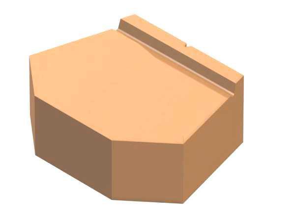
19 Mold Box Assembly Cavity Adjustment Process Measure the cavity length at the top of the Mold. Columbia assemblies the cavity to 1/32" under the modular block length. 17

20 Mold Box Assembly Cavity Adjustment Process Use a Machinist s square to check for draft on the cavity ends. Place the square inside the block cavity on the surface that the mold is being built on and slide the upright end of the square up against the end liner. A slight positive draft (light shining through near the bottom up to 1/64" per end) is acceptable and aids in stripping the product and reducing mold wear. Avoid Negative Draft! Adjust the draft using a soft headed mallet prior to fully tightening the mntg bracket bolts. 18

21 Mold Box Assembly Double check the measurements of the cavity, length, draft, and mounting bracket height. Torque all mounting bracket bolts to 120 ft.-lbs. when the height measurements are correct. 19

22 Mold Box Assembly With the cavity length and end draft adjusted, tighten the self locking setscrews which lock the partition plates. These are located on the underside of the end plate top flange. Note: The partition plates and end plates will prematurely fail during operation if the operator/assembler fails to keep the setscrews tight. 20
.")
23 Set the mold box in the mold alignment fixture or Block Machine. Place each head plunger/shoe assembly into their respective cavities, centering them. Ensure that a 1/32" clearance exists between the shoes and the partition plates. Place the head plate on top the head plungers and insert bolts (placing lock washers on the bolts). Do not tighten the bolts to full tension. This allows adjustment from side to side. Mold Box Assembly Head Assembly to Mold Cavity Alignment 21

24 Mold Assembly Alignment (Mold is shown in Mold Alignment Fixture) Bring Machine compression beam, or upper beam of Mold Alignment Fixture, down until it contacts the head assembly and bolt head assembly to compression beam. 22

25 Mold Assembly Alignment Cycle the head assembly in and out of the mold box to check for proper fit. Cycle it slowly the first few times just in case the shoes are not lined up correctly. When cycling the head assembly up and down, listen for any squeaks or clicks. Note their locations and adjust the head plungers or shoes for clearance. (Mold is shown in Mold Alignment Fixture) 23

26 Mold Box Assembly Conclusion When you are done testing the mold, Torque the head bolts to proper specifications and re-check for Proper clearances. The Mold Is Now Ready For Production 24

27 Machine Settings Block Machine settings are very important 1. PRESSURE GAUGE 2. COMPRESSION BEAM REGULATOR 3. FRONT LOW PRESSURE REGULATOR 4. FRONT HIGH PRESSURE REGULATOR REAR LOW PRESSURE REGULATOR 6. REAR HIGH PRESSURE REGULATOR 8. CLUTCH PRESSURE REGULATOR BRAKE PRESSURE REGULATOR 25
28 Machine Settings Recommended Block Machine settings Pneumatic Adjustments After start-up, adjustment of pneumatic control settings may be required to compensate for differences in material. To ensure the best quality block production, the following is offered as an aid to be applied in relation to an inspection of the block. Pallet Table High Pressure: This pressure should be set just high enough to hold the pallet firmly against the mold during compression. In general, a pressure that is too low will be indicated by a feather edge at the bottom of the block. The front and rear pressures do not necessarily have to be the same. Pallet Table Low Pressure. This pressure affects the proper filling of the mold and, consequently, block texture. In general, if block texture is loose or flaky, this pressure should be increased. The front and rear pressures do not necessarily have to be the same. Compression Beam Pressure: Proper setting of this pressure establishes even block texture. If blocks have uneven texture or if cracks appear in the block web, decrease compression beam air pressure slightly. Clutch Pressure: Proper setting of this pressure insures smooth operation and extended life of the clutch. Too low a pressure will cause slippage and excessive heat build up. Too high a pressure causes undue wear of clutch parts and possible damage to the motor. Brake Pressure: This pressure affects braking action of the vibrator shaft. Too low a pressure causes slow stop time. Too high a pressure causes high stress on brake parts. 26
29 Machine Settings Recommended Block Machine settings Pneumatic Controls Make the following preliminary pressure settings: Pallet Table Front High - 85 psi Pallet Table Rear High - 85 psi Pallet Table Front Low- 40 psi Pallet Table Rear Low- 40 psi Compression Beam - 70 psi Clutch psi Brake psi 27

30 Machine Settings Recommended Block Machine settings Pneumatic Controls Adjustment for Compression Head Air May Vary Depending On Product Settings should be psi lower than High Table Air 28
31 Machine Settings Recommended Block Machine settings Pallet Table and Compression Beam air pressure settings may vary according to block configuration and mix design. Preliminary settings are given as nominal. Avoid excessive pressures which can intensify vibration in the block machine. Place pallet table mode selector to MANUAL and make the following preliminary pressure settings: Pallet Table Front Low - 40 psi Pallet Table Rear Low - 40 psi 29
32 Machine Settings Recommended Block Machine settings Pallet Table Adjustment When a new mold is installed, the distance between the pallet table and mold must be adjusted to ensure proper pallet clearance. Two basic pallet table settings are suggested (see Figure 18). 1. Pavers or low height solids - Tight Pallet Check that pallet table surface is clean and free of all objects. Check that AUTO switch is in OFF position. Depress PUMP START pushbutton and open main shut-off valve. Close return line orifice valve. Switch the following manual selector switches in the sequence noted: COMPRESSION BEAM UP STRIPPER BEAM UP PALLET FEED BACK 30
33 Machine Settings Recommended Block Machine settings Pallet Table Adjustment cont. Exercise extreme caution while performing this adjustment with the pump unit on. Turn eccentric to the top position (mold in its up position) Place a clean pallet on the pallet table Turn the air to the pallet table on With proper spacers under the pallet table as determined by mold height, run the stripper beam to its up position. The pallet should contract the mold and slightly depress air bags. 31

34 Machine Settings Recommended Block Machine settings Pallet Table Adjustment cont. With clamp bolts loose, turn adjustable bushings until a gap is obtained between the head of the bolt and the adjustable bushing. This gap should be.030" and can be checked with a feeler gauge. Adjustable Bushing Feeler Gauge Bolt.030 Gap 2-1/8 Min. Clamp Bolt Set all four bolts and bushings exactly the same 32
35 Machine Settings Recommended Block Machine settings Pallet Table Adjustment cont. When adjusting table height, do not collapse air bags to less than 2-1/8" high. A lesser height will cause damage to the air bag. If a lower height is required, remove spacers from under pallet table assembly. Turn off air and tighten clamp bolts to 100 ft. lbs. This is only recommended as an initial set up. There are various methods that may be used depending on your mix, air pressures and product to be made. Contact the Columbia Block Service Dept. for help in determining how your pallet table should be set. General Block - Loose Pallet Follow the same procedure as above, except turn eccentric to the bottom position (mold in its down position). 33

36 Machine Settings Recommended Block Machine settings Other Machine Settings For Different Height Products Main Beam Cushion Adjustment 34

37 Machine Settings Recommended Block Machine settings Other Machine Settings For Different Height Products Lower Height Stops 35
38 Machine Settings Recommended Block Machine settings Compression beam down motion is controlled by compression beam stops. Appropriate spacers must be added or removed to allow the compression beam to lower to the point that the shoes extend to the bottom of the mold or 1/8" beyond. If changing to a shorter mold, spacers must be moved from top to bottom. If changing to a higher mold, spacers must be moved from bottom to top. The proper amount of spacers will allow the shoes to extend to the bottom of the mold or 1/8" beyond when the rubber bumper strikes the top of the feed box frame. Rubber Bumper Other Machine Settings For Different Height Products Compression Beam Hex Nut Spacers Compression Beam Stop Feed Box Frame Compression Beam Stops 36

39 Conclusion With Quality Molds & Proper Machine Setups Results Will Give You Quality Product 37
Mold Assembly for Models, 10, 12, 16, 22HF, 16HF, and 1600
 Knowledge Base Article Type: Instructions Mold Assembly for Models, 10, 12, 16, 22HF, 16HF, and 1600 Description: Instructions on How to properly assemble, clean and inspect, repair and rework molds, and
Mold Change, Quick Reference Guide, for Models, 22HF, 16HF, and 1600
 Knowledge Base Article Type: Instructions Mold Change, Quick Reference Guide, for Models, 22HF, 16HF, and 1600 Description: Instructions on How to Mold Change - Quick reference Guide. Instructions on how
Feed Drawer Rebuild, for Models, 22HF, 16HF, 1600 machines
 Knowledge Base Article Type: Instructions Feed Drawer Rebuild, for Models, 22HF, 16HF, 1600 machines Description: Instructions on How to properly remove and rebuild a Feed Drawer. WARNING Never work on,
Due to possible damage in shipping, the vertical stop assembly has been removed from this machine.
 Due to possible damage in shipping, the vertical stop assembly has been removed from this machine. To assemble, insert the threaded rod through the shroud opening in the top of the machine. Start the four
LORON SERVICE MANUAL / PARTS LIST SINGLE DOUBLE PALLET HANDLER CONTENTS: PAGE 1 Lift Truck Requirements General Installation Procedures
 LORON SERVICE MANUAL / PARTS LIST SINGLE DOUBLE PALLET HANDLER CONTENTS: PAGE 1 Lift Truck Requirements General Installation Procedures 2 Mounting Options Stop Block Adjustments 3 General Weekly Inspection
Operating, Servicing, and Safety Manual Model " Foot Shear CAUTION: Read and Understand
 Operating, Servicing, and Safety Manual Model 3000 52" Foot Shear CAUTION: Read and Understand These Operating, Servicing, and Safety Instructions, Before Using This Machine. SAFETY The purpose of the
Page 1. SureMotion Quick-Start Guide: LACPACC_QS 1st Edition - Revision A 03/15/16
 R K C T I Repair Kit Product Compatibility Repair Kit # Linear Actuator Assembly # LACPACC-002 LACPACC-003 LACP-16TxxLP5 (0.5-in lead screw pitch) LACP-16TxxL1 (1-in lead screw pitch) C P I R K 4 ea Flanged
RBP-1215B-RX DODGE RAM QUAD CAB RX3
 RBP-1215B-RX3 2002-2017 DODGE RAM 15-3500 QUAD CAB RX3 Passenger side RX-3 Side Step Drill Template Passenger side rear Modular Bracket (6) L Support Brackets Driver side rear Modular Bracket Driver side
INSTALLATION MANUAL FRONT. See pages 2 and 3 of this manual for configuration options. Level of Difficulty. Product Photo (center section only)
") INSTALLATION MANUAL FRONT Level of Difficulty Moderate Product Photo (center section only) All hardware listed below will be provided with the bumpers center section. Additional hardware will be supplied
INSTALLATION MANUAL FRONT Level of Difficulty Moderate Product Photo (center section only) All hardware listed below will be provided with the bumpers center section. Additional hardware will be supplied
Power Train Lift Max. Capacity: 1,250 lbs.
 655 EISENHOWER DRIVE OWATONNA, MN 55060 USA PHONE: (507) 455-7000 TECH. SERV.: (800) 533-6127 FAX: (800) 955-8329 ORDER ENTRY: (800) 533-6127 FAX: (800) 283-8665 INTERNATIONAL SALES: (507) 455-7223 FAX:
MODEL H " BYRD SHELIX CUTTERHEAD INSTRUCTIONS
 MODEL H9291 12" BYRD SHELIX CUTTERHEAD INSTRUCTIONS The Model H9291 12" Byrd Shelix cutterhead is designed to replace the straight-knife cutterhead on the Grizzly jointer Model G0609. The total procedure
COYOTE ENTERPRISES, INC. RIMLOC BLAST WHEEL MAINTENANCE & ASSEMBLY MANUAL
 COYOTE ENTERPRISES, INC. RIMLOC BLAST WHEEL MAINTENANCE & ASSEMBLY MANUAL Parts & Machinery for the Abrasive Blast Industry 27301 East 121st Street Coweta, Oklahoma 74429 (918) 486-8411 Fax (918) 486-8412
Form No Assembly & Operating Instructions for: SAFETY PRECAUTIONS
 Form No. 0230 Assembly & Operating Instructions for: 833 20300 83 2220 837 0-0008 078 SHOP PRESS Max. Capacity: 2 Ton These instructions are intended for various shop presses. Some models are shipped assembled
Sales & Service. JFK - Just For Kids. sasportonline.com. 135 Forestview Road 7879 Will Rogers Blvd.
 Sales & Service sasportonline.com SA Sport (Canada) SA Sport (U.S.A.) 135 Forestview Road 7879 Will Rogers Blvd. P.O. Box 40 Fort Worth, Texas Orillia, Ontario USA 76140 Canada L3V 6H9 Telephone: (705)
Oxford Stalls Installation Instructions
 Oxford Stalls Installation Instructions RAMM Horse Fencing and Stalls 13150 Airport Hwy. Swanton, OH 43558-9615 1-800-434-8456 Rev. 8/15/17 Before You Start Typical stall sizes are 10 x 10, 12 x 12 or
REPAIR INSTRUCTIONS. Cat. No Cat. No MILWAUKEE ELECTRIC TOOL CORPORATION. SDS Max Demolition Hammer. SDS Max Rotary Hammer
 Cat. No. 9-0 SDS Max Demolition Hammer Cat. No. -0 SDS Max Rotary Hammer MILWAUKEE ELECTRIC TOOL CORPORATION W. LISBON ROAD BROOKFIELD, WISCONSIN 00-0 8-9-0 d 000 8-9-0 d Special Tools Require Forcing
OPERATIONAL MANUAL V1.0. Removing/Replacing Blades
 OPERATIONAL MANUAL V1.0 BLUEROCK WS-212 Wire Stripper Removing/Replacing Blades CAUTION!! IMPORTANT!! DANGER!! WARNING!! DISCONNECT MACHINE FROM POWER BEFORE PROCEEDING!! Estimated Completion Time: 90
MODEL T TON HYDRAULIC PRESS INSTRUCTIONS (For Machines Mfd. Since 10/17)
") MODEL T1241 20-TON HYDRAULIC PRESS INSTRUCTIONS (For Machines Mfd. Since 10/17) For questions or help with this product contact Tech Support at (570) 546-9663 or techsupport@grizzly.com Identification
MODEL T1241 20-TON HYDRAULIC PRESS INSTRUCTIONS (For Machines Mfd. Since 10/17) For questions or help with this product contact Tech Support at (570) 546-9663 or techsupport@grizzly.com Identification
Inventory (Figure 2)
") MODEL T10127 12" SPIRAL CUTTERHEAD INSTRUCTIONS The Model T10127 indexable insert spiral cutterhead is designed to replace the straightknife cutterhead from the Grizzly jointer Model G0609. The total procedure
MODEL T10127 12" SPIRAL CUTTERHEAD INSTRUCTIONS The Model T10127 indexable insert spiral cutterhead is designed to replace the straightknife cutterhead from the Grizzly jointer Model G0609. The total procedure
INSTALLATION MANUAL IOWA MOLD TOOLING CO., INC. BOX 189, GARNER, IA MANUAL PART NUMBER:
 PARTS-1 Model 24562/28562 Crane INSTALLATION MANUAL IOWA MOLD TOOLING CO., INC. BOX 189, GARNER, IA 50438-0189 641-923-3711 MANUAL PART NUMBER: 99903701 Iowa Mold Tooling Co., Inc. is an Oshkosh Truck
Installation Instructions Kit, Base Rail Bracket Part # 31413
 Installation Instructions Kit, Base Rail Bracket Part # 31413 Dealer / Installer: Provide a copy of these Instructions to the end user of this product. These Instructions provide important operating and
Operating Instructions
 Operating Instructions Holding the material against the angle gauge slide it into the forming head. Be sure that the material remains against the gauge until work is finished. NOTE: This machine will handle
Operating, Servicing, and Safety Manual Model # 100 Standard Hydraulic Tubing Notcher Model #100-U Heavy Duty Hydraulic Tubing Notcher
 Operating, Servicing, and Safety Manual Model # 100 Standard Hydraulic Tubing Notcher Model #100-U Heavy Duty Hydraulic Tubing Notcher Model # 100 Standard Model #100-U Heavy Duty CAUTION: Read and Understand
Please read these Installation Instructions in their entirety prior to installing or operating this equipment.
 2014-2017 Ram 2500 (All beds) Please read these in their entirety prior to installing or operating this equipment. This hitch is rated to 30,000 lbs. Gross Towing Weight and 7,500 lbs. Tongue Weight Bolt
400A 40113V, 401A 40120V, & 401AL 40120VL ALUMINUM VERTICAL 4000 LB LIFT INCLUDES SCREW LEG ASSEMBLY INSTRUCTIONS
 12/11/07 PAGE 1 OF 12 400A 40113V, 401A 40120V, & 401AL 40120VL ALUMINUM VERTICAL 4000 LB LIFT INCLUDES SCREW LEG ASSEMBLY INSTRUCTIONS Thank you for purchasing our product! *Please read these instructions
Thank you for purchasing our product! *Please read these instructions and follow them step by step.*
 07/07/08.rev1 PAGE 1 OF 11 601AL VERTICAL 60120VL LIFT W/CHAIN DRIVE WINCH Thank you for purchasing our product! *Please read these instructions and follow them step by step.* Step 1. Separate and group
LEG CURL IP-S1315 INSTALLATION INSTRUCTIONS
 LEG CURL IP-S35 INSTALLATION INSTRUCTIONS Copyright 2009. Star Trac by Unisen, Inc. All rights reserved, including those to reproduce this book or parts thereof in any form without first obtaining written
CRYSTEEL S. this manual must be included with the vehicle after completing the installation.
 Website: www.tbei.com E-mail: sales@tbei.com CRYSTEEL S Grain Tipper mounting and operating instructions this manual must be included with the vehicle after completing the installation. Web Site E-Mail
MS25 OPERATION MANUAL
 SAFETY INSTRUCTIONS SPECIFICATIONS OPERATING INSTRUCTIONS MAINTENANCE ADJUSTMENTS REPLACEMENT OF PARTS MS25 DIAGRAM MS25 PARTS LIST MS25 OPERATION MANUAL SAFETY INSTRUCTIONS Please read these instructions
Type XTSR71 Sizes
 (Page 1 of 13) s 494-5258 Type XTSR71 s 494-5258 Figure 1 Thomas XTSR71 Coupling 1. General Information 1.1 Thomas Couplings are designed to provide a mechanical connection between the rotating shafts
1. Turn off or disconnect power to unit (machine). 2. Push IN the release bar on the quick change base plate. Locking latch will pivot downward.
. 2. Push IN the release bar on the quick change base plate. Locking latch will pivot downward.") Figure 1 Miniature Quick Change Applicators, of the end feed type, are designed to crimp end feed strip terminals to prestripped wires. Each applicator is set up to accept the strip form of certain specific
Figure 1 Miniature Quick Change Applicators, of the end feed type, are designed to crimp end feed strip terminals to prestripped wires. Each applicator is set up to accept the strip form of certain specific
Operating, Servicing, and Safety Manual Model # & 72 Ultimate Box & Pan Brake
 Operating, Servicing, and Safety Manual Model # 2800 48 & 72 Ultimate Box & Pan Brake CAUTION: Read and Understand These Operating, Servicing, and Safety Instructions, Before Using This Machine. 1-800-467-2464
KIT. Assembly Instructions. HayDay, LLC
 KIT Assembly Instructions HayDay, LLC 1-800-732-1654 www.stablegrazer.com Read completely through the assembly instructions before starting assembly. The Stable Grazer Kit comes in two boxes. Remove all
Typical Group D Rear Acoustical Cover Installation
 SERIES 60 SERVICE MANUAL 1. Gear Case Cover 5. Bolt 2. Gear Case 6. Acoustical Cover 3. Acoustical Cover Snap 7. Acoustical Cover 4. Acoustical Cover Clip 8. Nut Figure 1-179 Typical Group D Rear Acoustical
What is a fastener? A device to locate or hold parts
 What is a fastener? A device to locate or hold parts As a repair technician you will become skilled at removing, reconditioning, replacing, and installing fasteners. An important skill to learn is how
N. 15th Street, Middlesboro, KY FLIP TARP DUMP BODY INSTALLATION INSTRUCTIONS
 1-800-248-7717 1002 N. 15th Street, Middlesboro, KY 40965 FLIP TARP DUMP BODY INSTALLATION INSTRUCTIONS Congratulations on your purchase of a Mountain Flip Tarp Dump Body tarping system. With tarping systems
INSTALLATION & OWNER S MANUAL
 Rev. O p. 1 of 16 INSTALLATION & OWNER S MANUAL V4213 BALL CAGE KIT INSTALLATION & OWNER S MANUAL The contents of this envelope are the property of the owner. Be sure to leave with the owner when installation
HD installation guide
 JANUS INTERNATIONAL 1 866 562 2580 www.janusintl.c o m 1950 1950HD installation guide RIGHT DRIVE END SHOWN LH OPPOSITE LEFT TENSION END SHOWN RH OPPOSITE PUSH-UP OPERATION 1950 1950HD SHOWN A rolling
MODEL T " HELICAL CUTTERHEAD INSTALLATION INSTRUCTIONS
 MODEL T27696 12" HELICAL CUTTERHEAD INSTALLATION INSTRUCTIONS For questions or help with this product contact Tech Support at (570) 546-9663 or techsupport@grizzly.com Introduction The Model T27696 indexable
w w w. h d o n l i n e s h o p. d e TIMKEN BEARING CONVERSION TOOL GENERAL INSTALLATION -J04672 REV Kit Number Models
 -J067 REV. 008-07- GENERAL Kit Number 8-08 Models TIMKEN BEARING CONVERSION TOOL For model fitment information, see the P&A Retail Catalog or the Parts and Accessories section of www.harley-davidson.com
DRIVE COMPONENTS REMOVAL. 9. FXCW/C: see Figure Remove bolt (9), sprocket retainer (8), and thrust washer (7). NOTE PRIMARY DRIVE LOCKING TOOL
, sprocket retainer (8), and thrust washer (7). NOTE PRIMARY DRIVE LOCKING TOOL") DRIVE COMPONENTS REMOVAL PART NUMBER HD-7977 TOOL NAME PRIMARY DRIVE LOCKING TOOL S To remove the primary chain, remove compensating sprocket, clutch assembly and primary chain as an assembly:. Remove
DRIVE COMPONENTS REMOVAL PART NUMBER HD-7977 TOOL NAME PRIMARY DRIVE LOCKING TOOL S To remove the primary chain, remove compensating sprocket, clutch assembly and primary chain as an assembly:. Remove
Di-Acro 36 Power Shear
 OPERATOR S MANUAL & INSTRUCTIONS Di-Acro 36 Power Shear Di-Acro, Incorporated PO Box 9700 Canton, Ohio 44711 3713 Progress Street N.E. Canton, Ohio 44705 330-455-1942 330-455-0220 (fax) Revised 01/02 Sale
C h a s s i s F r a m e
 C h a s s i s F r a m e Chassis Frame Overview The Blue Bird Vision s chassis frame consists of two main C-channel rails which run the entire length of the bus, and several different kinds of cross members
Installation and Leveling Instructions for Micro/Level Wedge Style Isolators
 Technical Bulletin M/L 685 Installation and Leveling Instructions for Micro/Level Wedge Style Isolators 16WL50-1.25M6 with attachment bolt 16WM40-(1)1.25M6 with attachment bolt 12W with Anti-Skid Pad Vibro/Dynamics
WARNING. Failure to observe these instructions could lead to severe injury or death.
 INSTALLATION INSTRUCTIONS WINCH MOUNTING KIT Part Number: 80156, 80160 Application: 2008 Ford F150 Your safety, and the safety of others, is very important. To help you make informed decisions about safety,
What is a fastener? A device to locate or hold parts
 What is a fastener? A device to locate or hold parts As a repair technician you will become skilled at removing, reconditioning, replacing, and installing fasteners. An important skill to learn is how
MODULAR BUMPER INSTALLATION MANUAL
 MODULAR BUMPER INSTALLATION MANUAL Parts List* 1 Center section 1 Side extension, passenger / right 1 Side extension, driver / left 1 Side cap, passenger / right 1 Side cap, driver / left 1 Brush guard,
MM340 Installation Instructions IMPORTANT SAFETY INSTRUCTIONS - SAVE THESE INSTRUCTIONS
 MM30 Installation Instructions IMPORTANT SAFETY INSTRUCTIONS - SAVE THESE INSTRUCTIONS Please read this entire manual before you begin. Do not unpack any contents until you verify all requirements on PAGE.
installation guide
 JANUS INTERNATIONAL 1 866 562 2580 w w w. j a n u s i n t l. c o m 2000 2500 3000 installation guide RIGHT DRIVE END SHOWN LH OPPOSITE LEFT TENSION END SHOWN RH OPPOSITE PUSH-UP OPERATION 2000 2500 3000
MECHANICAL ASSEMBLY John Wiley & Sons, Inc. M. P. Groover, Fundamentals of Modern Manufacturing 2/e
 MECHANICAL ASSEMBLY Threaded Fasteners Rivets and Eyelets Assembly Methods Based on Interference Fits Other Mechanical Fastening Methods Molding Inserts and Integral Fasteners Design for Assembly Mechanical
ASSEMBLY AND CARE INSTRUCTIONS JUST FOR KIDS 355
 ASSEMBLY AND CARE INSTRUCTIONS VERSION: 8920100 (Revised 06/16) JUST FOR KIDS 355 SALES AND SERVICE spiethamerica.com Canada and International 135 Forestview Road, PO Box 40 Orillia, Ontario, Canada L3V
GearBoss AirPro Locker
 Installation and Owner s Instructions GearBoss AirPro Locker Wall Installation Island Installation Contents Important User Information...........................2 General...2 Manufacturer...2 Intended
LU6X-130 Instructions and Parts List (including LU6X Basic) Operating Instructions
 Operating Instructions") LORTONE LU6X-130 Item # 061-092 LU6X Basic Item # 061-090 LU6X-130 Instructions and Parts List (including LU6X Basic) Operating Instructions Introduction The LU6X is one the most versatile pieces of equipment
LORTONE LU6X-130 Item # 061-092 LU6X Basic Item # 061-090 LU6X-130 Instructions and Parts List (including LU6X Basic) Operating Instructions Introduction The LU6X is one the most versatile pieces of equipment
Gared Pro-S Portable Backstop
 Models: 9616 & 9618 Installation, Operation and Maintenance Instructions Please read all instructions before attempting installation or operation of these units SAVE THESE INSTRUCTIONS FOR FUTURE USE PUBLICATION
MM540 Installation Instructions IMPORTANT SAFETY INSTRUCTIONS - SAVE THESE INSTRUCTIONS
 MM50 Installation Instructions IMPORTANT SAFETY INSTRUCTIONS - SAVE THESE INSTRUCTIONS Please read this entire manual before you begin. Do not unpack any contents until you verify all requirements on PAGE.
INSTALLATION INSTRUCTIONS
 INSTALLATION INSTRUCTIONS Trans4mer Grille Guard/Winch Mount Kit 6334 For Chevrolet Silverado 500HD & 3500 This WARN Trans4mer system can be customized to give your Chevy Silverado a wide variety of looks,
PAN AND BOX BRAKE INSTRUCTIONS. Item #20649
 PAN AND BOX BRAKE INSTRUCTIONS Item #20649 The EASTWOOD 12 & 24 PAN AND BOX BRAKES are precision engineered metal working tools designed to produce accurate, variable length bends in angles up to 135 in
HDL(M)6 Nut/Screw Assembly
6 Nut/Screw Assembly") HDL(M)6 Nut/Screw Assembly Remove, repair, and reassemble the nut and screw assembly in your HDL series double lock vise. In these instructions when we refer to the front of the vise or nut/screw assembly,
HDL(M)6 Nut/Screw Assembly Remove, repair, and reassemble the nut and screw assembly in your HDL series double lock vise. In these instructions when we refer to the front of the vise or nut/screw assembly,
OWNERS MANUAL. Model No LB. POLY PRO SPIKER/SPREADER. CAUTION: Read Rules for Safe Operation and Instructions Carefully
 OWNERS MANUAL Model No. -0301 CAUTION: Read Rules for Safe Operation and Instructions Carefully 17 LB. POLY PRO SPIKER/SPREADER Safety Assembly Operation Maintenance Parts PRINTED IN U.S.A. FORM NO. 78
REEL BLADE / BED KNIFE ADJUSTING & SHARPENING
 Here s a QR code image that can be used to access this document on a portable device. Reel Mower Cutting Fundamentals The reel mower s cutting ability is the result of the corner edges of the reel blade
OPERATING INSTRUCTIONS AND PARTS LISTS
 3889560 REEL ALIGNMENT GAGE OPERATING INSTRUCTIONS AND PARTS LISTS WARNING You must thoroughly read and understand this manual before operating the equipment, paying particular attention to the Warning
PORTABLE ADJUSTABLE BASKETBALL SYSTEM
 Instruction Manual PORTABLE ADJUSTABLE BASKETBALL SYSTEM P A R T S L I S T 5 1/2 and 8 safe play clearance Item Qty Description Item Qty Description A 1 Portable Base Assembly M 4 1/2 Lock Nut B 2 Front
OPERATION & MAINTENANCE MANUAL
 OPERATION & MAINTENANCE MANUAL AUTOMATIC PECAN CRACKER Food Processing Equipment and Machinery Specializing in the Pecan Industry Mailing: PO Box 817, Mansfield, Louisiana 71052 Located: 280 Independence
PNEUMATIC C-RING TOOLS SC73462 SAFETY INSTRUCTIONS. WARNINGS Always read tool manual before operating.
 PNEUMATIC C-RING TOOLS SC73462 SAFETY INSTRUCTIONS WARNINGS Always read tool manual before operating. Always wear safety glasses while operating or while in the vicinity of a tool in operation. For testing,
Evaluation of In-Pavement Light Fixture Designs and Performance
 Evaluation of In-Pavement Light Fixture Designs and Performance Presented to: IES ALC Fall Technology Meeting By: Joseph Breen Date: Background In-Pavement Light Fixture Assemblies Utilize a Circle of
MODEL W1.0X305A(12 ) MODEL W1.0X610A(24 ) HAND BENDING BRAKE ASSEMBLY&OPERATING INSTRUCTION
 MODEL W1.0X610A(24 ) HAND BENDING BRAKE ASSEMBLY&OPERATING INSTRUCTION") MODEL W1.0X305A(12 ) MODEL W1.0X610A(24 ) HAND BENDING BRAKE ASSEMBLY&OPERATING INSTRUCTION 1 SAVE THIS MANUAL You will need the manual for the safety warning and precautions, assembly instructions, operating
MODEL W1.0X305A(12 ) MODEL W1.0X610A(24 ) HAND BENDING BRAKE ASSEMBLY&OPERATING INSTRUCTION 1 SAVE THIS MANUAL You will need the manual for the safety warning and precautions, assembly instructions, operating
H8508 Impact Wrench SERVICE MANUAL. Model (Serial Code FWN) Model (Serial Code FWP)
 Model (Serial Code FWP)") SERVICE MANUAL H8508 Impact Wrench Model 48755 (Serial Code FWN) Model 48760 (Serial Code FWP) Read and understand all of the instructions and safety information in this manual before operating or servicing
SERVICE MANUAL H8508 Impact Wrench Model 48755 (Serial Code FWN) Model 48760 (Serial Code FWP) Read and understand all of the instructions and safety information in this manual before operating or servicing
TOOLS REQUIRED FOR ASSEMBLY. Rubber Mallet or Plastic Tip Hammer PARTS REQUIRED FOR ASSEMBLY OF SINGLE ENTRY STARTER.
 TOOLS REQUIRED FOR ASSEMBLY Rubber Mallet or Plastic Tip Hammer Top Cover Support PARTS REQUIRED FOR ASSEMBLY OF SINGLE ENTRY STARTER Back Stop Divider Closed 'L' Upright Slotted Reinforcement Support
JK TrailGate JK TrailGate
 INSTALLATION INSTRUCTIONS INST-17-66-010_A JK TrailGate IMPORTANT: Thank you for purchasing this Poison Spyder product. Please read through this entire document before proceeding with installation. If
CONTROLS KIT FOR ALL # & # HARLEY DAVIDSON SPORTSTER MODELS
 INSTALLATION INSTRUCTIONS TC BROS. CHOPPERS PART #0-0075 & #0-0076 (No Pegs) FORWARD CONTROLS KIT FOR ALL 00-0 HARLEY DAVIDSON SPORTSTER MODELS If downloading & printing these instructions online, be sure
IDR assembly instructions:
 IDR assembly instructions: Required Tools: 2 X 12mm Open End Wrench 14mm open end wrench #2 Phillips Head Screw Driver (Drill with adjustable torque clutch recommended) 8mm nut driver (Supplied in IDR-AK)
Operator s Manual. Onion King 500N 501N 502N 503N ENGLISH
 Onion King 500N 501N 502N 503N Thank you for purchasing this Vollrath Food Processing Equipment. Before operating the equipment, read and familiarize yourself with the following operating and safety instructions.
Fortress Fe Posts must always be secured to the deck framing. Fortress Fe Posts should never be attached to only the deck boards.
 Installation Instructions for Fortress Horizontal Cable Panel System with UB-05 Brackets and Fe Posts It is the responsibility of the installer to meet all code and safety requirements, and to obtain all
LPK1550 Hydraulic Crimping Tool 15-ton
 SERVICE MANUAL LPK1550 Hydraulic Crimping Tool 15-ton Serial Code FYF Read and understand all of the instructions and safety information in this manual before operating or servicing this tool. Register
Repair Instructions. Replacing a La Z Time Mechanism Side Subassembly. Remove the Back(s): Remove the Mechanism Assembly: CAUTION.
: Remove the Mechanism Assembly: CAUTION.") Replacing a La Z Time Mechanism Side Subassembly Tools Required: Slotted Screwdriver Power Driver 8" Driver Extension Ruler Note: Extension springs are not typically used on non-chaise standard width styles,
Replacing a La Z Time Mechanism Side Subassembly Tools Required: Slotted Screwdriver Power Driver 8" Driver Extension Ruler Note: Extension springs are not typically used on non-chaise standard width styles,
OWNER S MANUAL. Safety. Please read this owner s manual before use and keep it at hand for reference. Warranty
 Please read this owner s manual before use and keep it at hand for reference. OWNER S MANUAL Safety Important safety instructions for using the INCRA Miter5000 Before using the INCRA Miter5000, read and
Please read BOTH these Installation Instructions and the General Towing Instructions before attempting to install or operate this equipment.
 2005-08 Pontiac G6 GT Please read BOTH these and the General Towing Instructions before attempting to install or operate this equipment. 1. Blue Ox towing products and accessories are intended to be installed
Side Winder R o u t e r L i f t.
 Woodpeckers PRECISION WOODWORKING TOOLS Side Winder R o u t e r L i f t. INSTALLATION INSTRUCTIONS The wrench handle must be pointing left in order to fully insert or remove it. Lift Wrench Once fully
DO35 MAINTENANCE INSTRUCTIONS
 CUSTOMER INFORMATION SHEET NO. 038 DO35 MAINTENANCE INSTRUCTIONS (DO35 V3 LAUNCHED PRODUCTION JUNE 2017) Table of Contents 1.0 Replacing Spindle Bushes V3... 22 2.0 Replacing Locking Mechanism V3... 6
ELECTRIC TOOL CORPORATION
 Cat. No. -0 / Hex Demolition Hammer Cat. No. 0-0 Spline Rotary Hammer MILWAUKEE ELECTRIC TOOL CORPORATION W. LISBON ROAD BROOKFIELD, WISCONSIN 00-0 -9-00 d 000 -9-00 d SpecialTools Require Forcing discs
Assembly Instructions
 Assembly Instructions 10 CONTRACTOR TABLE SAW Model No. 351.218330 Sears Brands Management Corporation, Hoffman Estates, IL 60179 U.S.A. www.sears.com/craftsman 31624.00 Draft (10/08/09) UNPACKING The
It is highly recommended that you use a thread lock compound such as Loctite brand on all threads to keep them from vibrating loose.
 Installation instructions for FC12 Forward Controls for Kawasaki Vulcan 750 It is highly recommended that you use a thread lock compound such as Loctite brand on all threads to keep them from vibrating
Please read BOTH these Installation Instructions and the General Instructions prior to installing or operating this equipment.
 Attachment Tab Height: 13 Attachment Tab Width: 24 Please read BOTH these and the General Instructions prior to installing or operating this equipment. Serial Number 1. Blue Ox towing products and accessories
SINCE 1922 P UBLICATION N O
 SINCE 1922 GARED SPORTS MICRO-Z SET-UP INSTRUCTIONS VERY IMPORTANT! READ INSTRUCTIONS CAREFULLY AND FOLLOW STEP BY STEP SET-UP PROCEDURE P UBLICATION N O. 5 5 1 7 5 2 9 1 6 Recommended tools and accessories.
Closet Carousel Installation Instructions. Models TKA 5 Through TKA 14 Equipped with Footswitch Controls
 Tools Required: Phillips Screwdriver (#2) Adjustable Wrench Level Tape Measure Utility Knife Electric Drill Drill Bits for Anchors Ladder (4 foot) Models TKA 5 Through TKA 14 Equipped with Footswitch Controls
OPERATOR'S MANUAL 46" SNOW BLADE. Model Numbers OEM IMPORTANT: READ SAFETY RULES AND INSTRUCTIONS CAREFULLY
 OPERATOR'S MANUAL 46" SNOW BLADE Model Numbers 190-833-OEM IMPORTANT: READ SAFETY RULES AND INSTRUCTIONS CAREFULLY MTD PRODUCTS INC. P.O. BOX 368022 CLEVELAND, OHIO 44136-9722 PRINTED IN U.S.A. FORM NO.
SERIES I MILLING MACHINES
 INSTALLATION, OPERATION, MAINTENANCE, AND PARTS LIST SERIES I MILLING MACHINES TP5260 Revised: August 29, 2005 Manual No. M-450 Litho in U.S.A. Part No. M -0009500-0450 June, 2003 MAINTENANCE PROCEDURES
FLIP TARP SINGLE & DOUBLE UNDERBODY TRAILERS
 1-800-248-7717 1002 N. 15th Street, Middlesboro, KY 40965 FLIP TARP SINGLE & DOUBLE UNDERBODY TRAILERS INSTALLATION INSTRUCTIONS Congratulations on your purchase of a Mountain Flip Tarp Trailer system.
RangerWare Fiberglass Door System Installation Instructions P/N
 Page 1 of 9 RangerWare Fiberglass Door System Installation Instructions P/N 2878016 ORDER OF INSTALLATION Note: To assure proper order, read all Accessory Installation Instructions before beginning. 1.
SERVICE MANUAL AND PARTSLIST
 SERVICE MANUAL AND PARTSLIST Next 20 CONTENTS WHAT TO DO WHEN... 1~3 SERVICE ACCESS FACE COVER... 4 TOP COVER... 4 BASE COVER... 5 REAR COVER... 6 FRONT COVER... 7 MECHANICAL ADJUSTMENT NEEDLE THREAD TENSION...
w w w. h d o n l i n e s h o p. d e AUTOMATIC COMPRESSION RELEASE TOOL GENERAL INSTALLATION -J04654 REV Kit Number Models
 -J05 REV. 008-0- GENERAL Kit Number 98-08 Models AUTOMATIC COMPRESSION RELEASE TOOL For model fitment information, see the P&A Retail Catalog or the Parts and Accessories section of www.harley-davidson.com
18000 HDL FOUR POST LIFT LB CAPACITY INSTALLATION AND OWNER'S MANUAL
 18000 HDL FOUR POST LIFT 18000 LB CAPACITY INSTALLATION AND OWNER'S MANUAL WARNING! Do not raise a vehicle unless the front stops are in place, the parking brake is set, and the wheels are chocked. Stay
8" BENCH SHEAR INSTRUCTIONS. Item #20198
 8" BENCH SHEAR INSTRUCTIONS Item #20198 Your EASTWOOD 8 BENCH SHEAR for metal cutting is designed for quickly and cleanly cutting mild steel, aluminum and other metals. Torque-amplifying, compound linkage
Maintenance & Parts list for:
 Maintenance & Parts list for: Industrial gun GB 2 Juni 2017 This Maintenance & Parts list for industrial gun is prepared by : Winchester Europe Service V. Parbst & Søn as a comprehensive maintenance guide
WARNING. BX Ford Explorer With Adaptive Cruise Control & Eco Boost Installation Instructions
 Please read BOTH these and the General Instructions before attempting to install or operate this equipment. 1. Blue Ox towing products and accessories are intended to be installed by Blue Ox Dealers who
MM750 Installation Instructions
 MM750 Installation Instructions IMPORTANT SAFETY INSTRUCTIONS - SAVE THESE INSTRUCTIONS Please read this entire manual before you begin. Do not unpack any contents until you verify all requirements on
INSTRUCTION MANUAL Q-HYDRAULIC
 Dat: 15.04.02 No: 94-BA 5039E/1b TABLE OF CONTENTS Part III 3.0 Type code explanation 3.1 Service connections 3.2 Impeller clearance adjustment 3.2.1 Wear of wearing parts 3.2.2 General notes to adjustment
Mechanical Frappe Press
 Mechanical Frappe Press Operation Manual CONTENTS OPERATIONAL INSTRUCTIONS PRECAUTIONS PART NAMES INCLUDED ITEMS BASIC OPERATION MAINTENANCE REPLACEMENT PARTS Thank you for using The Frapptastic Five Mechanical
OPERATION, PARTS & MAINTENANCE MANUAL MODELS HB73-16 HB97-18 HB97-16 HB97-12 HB HB HB HB145-18
 OPERATION, PARTS & MAINTENANCE MANUAL MODELS HB73-16 HB97-18 HB97-16 HB97-12 HB121-18 HB121-16 HB121-14 HB145-18 Proudly Made in the USA 2 3 4 FOREWORD This manual has been prepared for the owner and operators
Copyright Black Box Corporation. All rights reserved Park Drive Lawrence, PA Fax
 Copyright 2003. Black Box Corporation. All rights reserved. 1000 Park Drive Lawrence, PA 15055-1018 724-746-5500 Fax 724-746-0746 JULY 2003 RM3010A RM315-R2 RM323-R2 RM329 RM451 RM457 RM3020A RM316 RM324-R2