The Introductory Guide to Designing
|
|
|
- Noah Harrington
- 6 years ago
- Views:
Transcription

1 The Introductory Guide to Designing Rotationally Molded Plastic Parts Association of Rotational Molders Internaional
2
3 A Word about the Data Being Presented The data presented in this booklet has been collected from many sources which are believed to be reliable; however, no express or implied warranty can be made to its accuracy or completeness. No responsibility or liability is assumed for any loss or damage suffered through reliance on any information contained herein. The final determination of the suitability of any information for the use contemplated for a given application remains the sole responsibility of the user. Acknowledgements We wish to acknowledge those members past and present who have contributed to this publication. The information contained in this design manual was edited and illustrated by processor, mold maker, plastics material supplier, and professional members of the Association of Rotational Molders International. Copyright 1982, Association of Rotational Molders International, Glen Ellyn, Illinois U.S.A. All Rights Reserved. Reprinted 1983, 4/88. Revised reprinted 7/90 Revised reprinted 3/93 Revised reprinted 9/99 Reprinted 8/01 Reprinted 8/05 Reprinted 7/10 All rights to the use of the information contained in this booklet are reserved. Any reproduction of the photographs, drawings or text of this publication without the express written permission of the Association of Rotational Molders International is forbidden. For additional information regarding this design manual and for a listing of suppliers and services, please contact the Association of Rotational Molders International. 1 Introduction This booklet has been prepared as a guide for design engineers and for other professionals in the plastics field who want to know how to design high quality, low cost rotationally molded plastic parts. Contents Advantages of Rotational Molding Rotational Molding Process Molds for Rotational Molding Plastic Material Considerations Special Plastic Materials and Composites Product Design Considerations Nominal Wall Thickness Wall Thickness Uniformity Varying Wall Thicknesses Flatness Considerations Minimum Wall Separation Corner Angle Limits Reinforcing Rib Kiss-Off Ribbing Draft Angles Corner Radiuses Holes Undercuts Tolerances Design Factors Plastic Material Factors Mold Design and Construction Factors Processing Factors Molded-In Threads Molded-In Inserts Finishing and Decorating Computer Aided Design Volume of Mold Cavity Versus Volume of Powder Shot Weight Product Dimensional Change Due to Heating or Cooling Design Wall Thickness Cylindrical Tank Hoop Stress in Cylindrical Tank Wall Calculating Part Weight Assuming a Given Wall Thickness Estimating Part Weight in Polyethylene Estimating Part Wall Thickness Closed Cylinder Calculating Deflection Conversion Formulas/Useful Information Equations for Area of Plane Shapes
4 This booklet answers these four basic questions and more. You will find it useful whether you are a designer, a specifier, or a buyer. Rotational molding is a plastics processing technique that is ideally suited to producing relatively large, hollow, seamless parts which are partially or totally enclosed. This process has been in existence since the early 1930s. The introduction of micronized polyethylene in the late 1950s has provided the industry with an ideal material for the rotational molding process. Since that time, the industry has continued to grow at a steady rate. Designers of plastic parts turn to rotational molding to produce small or large parts of unusual shape that cannot be produced as one piece by other processes. Parts as small as a ping pong ball or as large as a 22,500-gallon tank can be made by rotational molding. Relative to their size, rotationally molded parts can have thinner walls than similar parts made by other processes. Rotational molding tends to produce an increasing wall thickness on outside corners of parts, which gives the process a distinct advantage over blow molding and thermoforming since these processes tend to produce thin outside corners. The added thickness and corresponding increase in strength at the outside corners is usually an advantage, especially in large parts. Rotational molding is a low-pressure process, and the strength required from the molds is minimal. This results in its ability to produce large or complex parts on short notice, using low cost molds. Due to the low tooling cost, rotational molding is ideally suited to producing prototypes, small or large quantities of production parts and the initial production of parts that will eventually be made by some other more Advantages of Rotational Molding What is the rotational molding process? What are its advantages to users? How do you design rotationally molded parts? What plastics are being molded? capital-intense process, when the required quantities justify such an expenditure. The low processing pressure involved in rotational molding has the added advantage of producing parts which are relatively stress free, as compared to other high pressure processes. This advantage of the process is especially important when considering large, load-bearing parts in applications which must provide corrosion or stresscrack resistance. The surface finish, which includes sandblast, shot peen texture, even wood grain and color through dry blending or compounding of rotationally molded parts, can be tailored to suit the product s requirements. Metal inserts or integrally molded-in threads are possible with rotationally molded parts. Reversal parts with closely spaced double walls are common, enabling foam injection for insulation and structural purposes. Many parts are molded with little or no draft angle. With some materials, it is possible to produce parts with undercuts. Many thermoplastics and some thermosetting plastics can be rotationally molded; however, the most commonly molded plastics are thermoplastic, polyethylene, polyvinylchloride, nylon and polycarbonate. Unsaturated polyester and crosslinked polyethylene are the most often used thermosetting plastics. The following pages will give the design engineer a better understanding of the rotational molding process and its own unique capabilities. 2
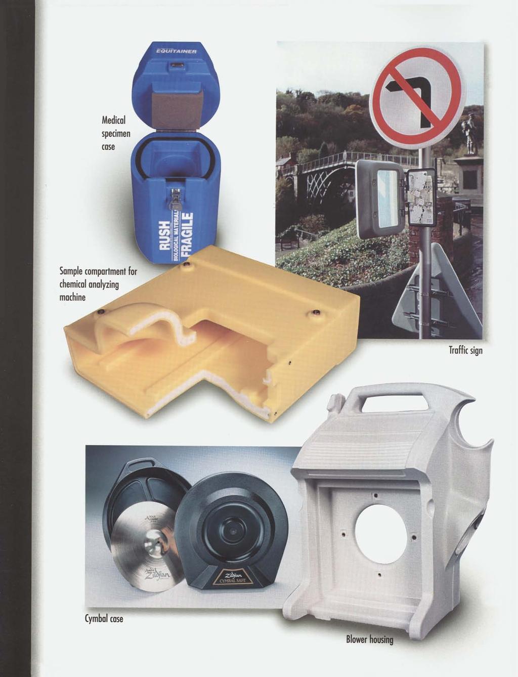
5 Rotational molding is well known for its ability to produce tanks of all kinds. This process, however, is also ideally suited to producing other types of products as well. Rotationally molded parts are used in the health and science field as instrument housing, carrying cases, dental chairs and other types of furniture. In the recreational field, boats, truck cabs, motorcycle shields, swimming pool filter housings, surfboards and balls of all kinds are made by the rotational molding process. Riding toys such as hobbyhorses and car bodies are common. Climb-on, -over, -through and slide-down toys have been made by the rotational molding process. The point-of-sale advertising industry uses rotational molding to produce a wide range of mannequins and other types of advertising devices which both display and store the products. Figure II Figure IIA Safety devices such as marker floats and buoys, highway safety barriers, and road markers are rotationally molded products. In the industrial field, rotationally molded parts find use as instrument housings, carrying cases, instrument carts, lighting globes and gasoline tanks for all kinds of vehicles. Household products such as planters, serving trays and carts, room dividers, refuse containers and picnic tables are made by rotational molding. Agricultural, chemical-processing and specialty tanks of unusual shape for boats and recreational vehicles are major markets for rotational molding. Figure IB Rotational Molding Process Figure I Figure IA Figure IC In rotational molding, a premeasured amount of plastic material in liquid or powder form is placed in a cavity and the mold is closed. The amount of material required is determined by the wall thickness desired. The molding machine then indexes the mold into an oven (Figure 1B) where the mold and subsequently, the plastic is brought up to the molding temperature. As the mold is heated, it is rotated continuously about its vertical and horizontal axes. Usually a four (major) to one (minor) rotation ratio between 6-8 r.p.m. is used. A reverse rotation can also be achieved to fill small intricacies and hidden areas of the mold. The biaxial rotation brings Figure IIB all surfaces of the mold into contact with the puddle of plastic material. The mold continues to rotate within the oven until all the plastic material has been picked up by the hot inside surfaces of the cavity. The mold continues to rotate until the plastic material densifies into a uniform layer of melt. While continuing to rotate, the machine moves the mold out of the oven and into a cooling chamber (Figure 1C). Air or a mixture of air and water cools the mold and the layer of molten plastic material. This cooling process continues until the part has cooled sufficiently to retain its shape. The machine then indexes the mold to the loading and unloading station (Figure 1A). The mold is then opened and the part removed. A new batch of material is then placed in the cavity, the mold is closed and the process is repeated. There are several different kinds of rotational molding equipment currently in use, but the three-station layout shown in Figure 1 is the most common. The biaxial rotation is usually achieved by a series of gears or chains and sprockets such as are shown in Figures 11A and 11B. Small, multiple cavity molds of the same parts are usually centrally mounted (as shown in Figure 11A). Large, single-cavity molds are frequently mounted offset (as shown in Figure 11B) in order to make maximum utilization of the molding machine s capacity. Plastic parts of totally dissimilar shape, such as small doll heads and large refuse containers can sometimes be molded simultaneously on the same machine. The only limiting factor is that the oven temperature and cycle time must be compatible with the wall thickness of the various parts and the materials being used. The arm must also be balanced to achieve uniform wall thickness and to prevent wear on motors, gears and chains. For a given part size, rotational molding equipment is relatively low in cost, compared to other more capital intense processes, such as injection or blow molding. However, long cycles, quantity of resin, finishing and shipping could increase piece part price. 3
6 Molds for Rotational Molding Rotational molding is a low pressure process and molds are primarily a thin hollow shell that defines the outside shape and surface of the part. The inside surface of the part is formed by the thickness of the nominal wall and does not require internal cores. In many cases, rotational molding molds are relatively low in cost when compared to other type molds such as those used for blow or injection molding. There are many different approaches to producing molds for rotational molding. Determining which type of mold to use depends upon several factors: tolerances, aesthetics of the part, geometry, lead-time, and budget. Cast Molds Cast aluminum molds are widely used in the rotational molding industry because they offer a convenient means of creating complex shapes. Casting offers excellent repeatability for multiple molds and parts varying from the very small to the large (e.g. kayaks and 400 gallon containers) can be produced. Cast molds are particularly suited to products requiring great detail or intricate shapes. There are a number of ways to design and enhance cast tools for longevity, molder ease, and the construction and design of specific products. While much detail can be cast into the mold from the model or pattern, many textures and finishes can be added to the casting through glass bead or shot peening blasting and polishing, with relative ease, due to the strength and malleability of cast aluminum. Multiple piece molds can be designed to allow part removal for undercuts or unusual shapes. Mold wall thickness can be varied or heat fins cast into the tool to produce desired heat transfer requirements, thus producing thicker/thinner walls. One of the greatest advantages of cast aluminum molds is the ease of revising the tool to incorporate design changes or revisions. Cast aluminum molds can be updated and refurbished many times at a comparatively low cost compared to purchasing new tools. For numerous changes or ones that entail a lot of work, the pattern can be revised and the mold recasted. Machined Molds CNC machined molds are typically used when extreme accuracy, short leadtimes, acid etched surface and/or complex geometry are required. These tools are machined from forged aluminum directly from solid model CAD data. With today s high-speed machining technology, this is one of the fastest ways to produce rotational molds. The forged aluminum provides increased durability over cast molds and an excellent surface for acid etching. The machined parting lines result in minimal witness lines. Machined molds are ideal when complex part geometry requires multiple piece molds and extensive parting lines on highly aesthetic products. The typical overall tolerance on a machined aluminum mold is ± Fabricated Molds Fabricated molds from carbon steel, stainless steel and aluminum are widely used for parts of simple geometry and are particularly suited to very large parts. Complex shapes can be fabricated with some limitations. Duplicate molds can be made within the tolerances of human ability because a pattern is not used to make the mold. 4 Steel fabricated molds have the advantage of not experiencing the heat expansion differences between aluminum and the steel mounting structures. Generally, the completed units are lighter weight than cast aluminum molds. A lower cost may be realized because of not requiring the expense of a full size pattern. Fabricated steel molds are very durable. Aluminum and stainless steel will not rust like carbon steel in the harsh environment of heating and cooling. The strength and toughness of steel is an advantage in any maintenance requirements as well as revising because of design changes. Revising is at least as low cost as cast molds. The production of surface textures in steel molds is difficult, although embossed patterns and logo plates are available. Electroformed Nickel Molds Electroformed cavities are less common, but they have the advantage of being able to reproduce faithfully fine details such as wood or leather graining which would be difficult to achieve by other techniques. Figurine molds are a good example of an application where large numbers of identical cavities can be made economically. Electroformed cavities are frequently used to produce hollow undercut cavities for the molding of flexible materials such as polyvinylchloride. Doll head molds, in which the entire part is pulled out through the neck opening, are a good example of this approach. The size of the electroformed molds is limited by the size of the plating tanks. Electroformed molds have been used to produce items as small as a doll s head and as large as a canoe or boat hull. Vapor-Formed Nickel Molds Although similar to electroformed molds, vapor-formed nickel molds are more costly. They have the advantage of producing a more uniform cavity wall thickness with less buildup of nickel on sharp outside corners. Non-Metallic Molds Liquid thermosetting polyester and epoxy materials are formed and cured at room temperature. The molds used for these types of materials can be fabricated by using room temperature curing silicone and fiberglass fabrication techniques. Temperatures at which these molds are run usually do not exceed 450 F.; therefore, cycle times are extended. In a typical gas oven, this type of mold will yield up to 100 parts, making this a method for prototyping. Some new types of composite molds (CMT) have electrical heating elements embedded in the mold material so that the mold can be heated without the need for an oven. Summary To a great extent, the quality and especially the tolerances on a rotationally molded part, like plastic parts made by other processes, are dependent upon the quality and precision incorporated into the mold. There is no substitute for a good quality mold. Each of the various types of molds described here has its own unique advantages and disadvantages. A rotational molder can provide advice as to which type of mold will be the best for a particular application. Also, new technology is being researched in mold construction to shorten cycle times and increase efficiency.
7 Plastic Material Considerations Any plastic material can, theoretically, be rotationally molded. This includes both thermoplastics, which melt or soften and flow when heated (and harden when cooled) and thermosets, which crosslink or cure (and harden when heated) and cannot be remelted. There are two primary requirements for a material for rotational molding. First, it must flow adequately to coat the cavity evenly as the mold is rotated. Second, it must be thermally stable at the oven temperature at which it is processed and for the oven cycle time required. Most plastic materials for rotational molding are special formulations which were developed to have high flow, superior thermal stability, and narrow molecular weight distribution for excellent physical properties. Most bulk resins have a melt between 3-6 g/10 minutes, although engineered resins reach above or below that. Most resins are supplied in a fine powder (35 mesh) but some resins are in liquids or very small pellets known as micropellets. Common Rotationally Moldable Materials The following list is comprised of the more commonly used plastic materials and their general characteristics. Polyethylene LLDPE (Linear Low Density Polyethylene) Flexible to medium stiffness, excellent impact, chemical, and environmental stress crack resistance, easy to process and most are available with UV stabilizer. Most will meet the requirements of FDA, USDA, NSF and UL (Horizontal Burn). Applications include tanks, containers, toys and playground equipment. HDPE (High Density Polyethylene) Stiffest of all polyethylene. Excellent chemical resistance and good impact. Easy to process and most available with a UV stabilizer. Most will meet the requirements of FDA, USDA, NSF, and UL (Horizontal Burn). Applications include tanks, ducting, and parts requiring maximum rigidity. XLPE (Crosslink Polyethylene) Contains a cross linking agent which reacts with the material during the molding cycle forming a crosslinked molecular structure similar to thermoset. Properly crosslinked resins provide excellent impact, environmental stress crack resistance, and weatherability. Applications include gas and oil storage tanks, trash containers, as well as parts requiring maximum toughness. Also good for parts being used in cold temperatures. Most do not meet FDA, USDA or NSF requirements. Specialty Polyethylenes Polyethylenes can be modified to provide specific properties. Flame retardant additives can be incorporated into polyethylene to allow parts to pass the stringent UL vertical burn. Applications can include hospital, airline and military containers. Foaming or blowing agents can be incorporated into a small to medium size pellet and used with powder in a system that can mold a part in one step that has an outer skin of polyethylene and a foam filled core. Applications requiring floatation, insulation or sound reductions can be molded with this resin system. Polyethylenes can be chemically modified to allow the resin to adhere to metals or other resins. These resins, commonly known as rotolining resins, can be used to line metal vessels for corrosion and chemical resistance. A rotolining resin can also serve as a bonding or tie layer for co-rotational molding in which two dissimilar resins are joined. EVA Copolymer Excellent low temperature flexibility. Available in UV stabilized and FDA approvable grades. Applications include soft toys and blending with other materials to improve impact strength. Polyvinylchloride PVC compounds can be molded in either liquid or powder form. The liquid plastisols are fluid suspensions of fine particle size resins in plasticizing liquid. PVC compounds are moderate in cost and are easily processed. They can be formulated to produce parts ranging from flexible to semi-rigid with Durometer hardness ranges of 60 Shore A to 65 Shore D. Applications include balls, doll heads, teething rings, planters, novelty items and flexible bellows. Nylon Type 6 Excellent tensile strength, stiffness and impact strength. High heat resistance, so properties are maintained at elevated temperatures. Excellent chemical resistance. Moderate in cost. Applications include military fuel tanks, hydraulic oil and solvent tanks, grain buckets, and air ducts. Type 12 Moisture absorption, melting point, and mechanical properties are lower than Nylon 6 but more easily processed. Applications include heating and air conditioning ducts, gasoline tanks and chemical tanks. Polycarbonate Excellent mechanical properties including stiffness, tensile strength and creep resistance. Highest impact strength of all rigid plastics. High heat resistance. Can be molded clear. Applications include light fixture globes, snowmobile engine hoods, shipping containers and other applications where high heat resistance and toughness are required. Polypropylene Stiffer than most polyethylene with higher heat distortion temperature, autoclavable and has excellent environmental stress crack resistance. Polypropylene requires cryogenic grinding to be used in a powder. Applications include bio-chemical vessels, solar panels, and medical storage containers. 5
8 Special Plastic Materials and Composites At one time or another, virtually all thermoplastics and most thermosetting plastic materials have been rotationally molded, at least experimentally. In most of these special cases, markets have not grown large enough to justify the development of the specially compounded plastics that would be suitable for the rotational molding process. The following list of plastic materials are used occasionally for the rotational molding of specialty products: 1. LDPE 8. Polybutylene 2. Acetal 9. Other Grades of Nylon 3. Acrylic 10. Polyurethane 4. Cellulosics 11. SAN 5. Epoxy 12. Silicon 6. Fluorocarbon 13. Polyesters 7. Phenolic 14. EBA The physical properties of the plastics referred to in this manual are summarized in the Modern Plastics Encyclopedia and the Gordura Company s Desktop Data Bank. This information may be available from other databank sources. Additives The properties and appearance of any material can be changed with additives. Most materials already have an antioxidant, which prevents degradation during processing, and a UV stabilizer for long term outdoor protection. Colorants, known as dyes or pigments, are very common to material used in rotomolding. The colorant can be dry blended into the powdered resin by the rotomolder or be hot melt compounded into the resin using pellets or powder. Other common additives are flow lubricants and antistatic agents which are used for the purpose their name implies. The rotomolder can also choose to use a blowing or foaming agent in its neat form if they do not prefer to use a one step system previously discussed. These agents can be introduced during the molding cycle or used as a post molding product. Another common group of additives are reinforcements. Although not often used, glass fiber or other reinforcements can be added to increase stiffness. Fillers and extenders can also be added to the plastic resin. These are generally low-cost inorganic materials which are added to increase to bulkiness and thereby reduce the material cost. Since properties of an extended material often suffer, they are generally used for less critical applications. However, some fillers enhance specific properties such as reducing material shrinkage, increasing stiffness, increasing heat deflection temperature or thermal conductivity or reducing tensile strength. Like the other additives, the fillers and extenders are fine powders and can be dry blended with the plastic powder or compounded into the pellets. The design engineer should also recognize that all of these additives and special molding techniques could be combined to produce very sophisticated parts. For example, it is technically feasible to compound a plastic material which is colored, foamed, reinforced and fortified to provide ultraviolet light stability and fire retardancy, which can be molded with two or more layers of material for special effects. Product Design Considerations The design of a rotationally molded plastic part, like any other part, must simultaneously satisfy three basic requirements. First, the part must provide the end-use functional requirements. While designing the part, the design engineer must also take into account the part design requirements or limitations of the material and process which has been specified. While satisfying these first two requirements, the designer must not lose sight of the fact that the product must also fall within a specified cost range in order to be economically feasible. Most design projects are a compromise between these basic requirements. Once the design engineer has created a basic shape that will satisfy the functional requirements of the product, his attention should then be given to finalizing the design of each detail on the part in order to put the overall part design into the best condition for the material and process that has been chosen. The correct handling of design details such as wall thicknesses, corner radiuses, draft angles, etc., can mean the difference between success and failure. The following design guidelines will help the design engineer to create high quality rotationally molded plastic parts which will be economical to produce. Rotational molding, like all other plastic-processing techniques, has its own unique advantages, disadvantages and part design requirements. The design engineer must recognize that there are no forces which push the plastic material through the mold as is the case with thermoforming and injection or blow molding. In rotational molding, the mold rotates through a puddle of liquid or powdered plastic and the plastic adheres to the hot surfaces of the cavity to build up the desired wall thickness. Considering this situation, the ideal design for a rotationally molded part is any hollow shape where the various elements in the part design are smoothly blended from one contour to the next. The smooth blending of contours will result in a finished product which has increased strength, is easier to produce, and is more economical. The successful design of any plastic product is dependent, to some extent at least, on proportioning the design of the part to accommodate the specific plastic material that is to be used. A rigid, high temperature, low mold shrinkage, hard flow, amorphous material, such as polycarbonate, has different design and processing requirements than a softer, low temperature, high mold shrinkage, easy flowing material, such as crystalline polyethylene. Each plastic material has its own unique design requirements. In relationship to some of the older plastics processing techniques, rotational molding is comparatively new. Some of the design guidelines are just now being formulated into rules and there still remain many unanswered questions. The following design guidelines would be good practice to apply to any plastic material that will be rotationally molded. Some of the plastics have special design requirements. This data has been included in these guidelines, as it was available. 6
9 Nominal Wall Thickness The nominal wall of the part is its basic frame which defines its shape. Once the basic shape has been established, other details can be added to it in order to provide other features in the finished part. The nominal wall (or the frame of the part) is the single most important element in the design and it must be handled correctly. Once the outside shape has been defined, the designer must remind himself that the inside of the part will be free-formed and that its size and shape will be dependent upon the outside size and shape minus the wall thickness. The type of plastic material used and the thickness of the nominal wall will determine the strength and load bearing capability of the finished part. The wall thickness required to sustain a given load can be determined by the conventional techniques that are applied to other plastic parts; however, as molded physical properties must be used in these calculations. The nominal wall thickness will have a direct effect on the cost of the finished part. In addition to the added cost of the material used in a thicker wall, the cycle time and the energy required to heat and cool the plastic will be directly related to the wall thickness. For example, a.030 inch increase in the wall thickness of a Nylon 6 part will result in an increased oven time of approximately two minutes. Wall Thickness Uniformity As far as wall thickness uniformity is concerned, rotational molding is a designer s dream come true. The nature of the process automatically produces uniform wall thickness, even in the most unusual shapes, which is a distinct advantage over other processes such as blow molding or thermoforming. The ideal way in which to specify the wall thickness on a part that is to be rotationally molded is to specify the nominal wall thickness and to indicate the minimum allowable wall thickness that can exist anywhere on the finished part. These specifications allow the molder the maximum latitude in producing a good quality, low cost part. Depending upon the part s size and shape and the material being molded, a commercially acceptable wall thickness tolerance of ±20 percent is usually possible. A wall thickness specification of ±10 percent would be considered to be a precision tolerance that could be achieved only with added cost and difficulty. An ideal nominal wall thickness for most materials would be in the range of.125 inch. A.125 inch wall thickness provides a good compromise with cycle time, ease of processing, strength and cost. Other wall thicknesses can be provided if the functional requirements of the product justify them. Wall thicknesses as thin as.030 inch have been produced successfully in polyvinylchloride and thermoplastic polyester materials for such applications as medical drainage bags and waterbed mattresses. It is generally agreed that parts to be produced in nylon should be limited to a wall thickness of.060 inch to.750 inch, but 1.25 inch thick parts are possible. Polycarbonate wall thicknesses are typically in the range of.060 inch to.375 inch, with.125 inch being an ideal thickness. Polyethylene wall thicknesses are usually in the range of.125 inch to.25 inch. However, large parts in cross-linked polyethylene have been made with wall thicknesses as great as two-plus inches. A wall thickness of one inch is not uncommon. The designer must remember that these thick walls can be made; however, the cycle time will be very long. Consideration must be given to thermal degradation of the plastic material because of the prolonged oven heating cycle required for thick walls. This is especially true with heat sensitive materials. Rotational molding provides the design engineer with the unique capability to increase or decrease the wall thickness of a part after the mold has been built and sampled. The final wall thickness of the part can therefore be established after actual in-use testing of the part. Few other plastics processing techniques offer the designer this advantage. Rotationally molded parts usually contain gradually thickening walls on the outside corners and slightly thinner walls on the sharp inside corners. Because of this fact, wall thickness tolerances are usually understood to refer to the nominal wall only and not the corners of the part. This subject will be covered in greater detail in the section concerning radiuses. Varying Wall Thicknesses Non-uniform wall thicknesses can be produced within limits. Advanced techniques, such as varying the wall thickness of the mold or changing the mold construction material to achieve increased or decreased thermal conductivity, have been used successfully. Preheating or shielding specific portions of the mold from the oven s heat have also proved effective. In each case, the molder has used the fact that the portion of the mold which reaches molding temperature first will accumulate the thickest layer of plastic. These techniques have been put to good use in producing vertical storage tanks with gradually thickening walls near the bottom of the tank where the loads are greater. Flatness Considerations Rotationally molded parts, like blow-molded parts, are formed in hollow molds with no internal cores. This makes it difficult to guarantee flatness on large flat panels. A commercially acceptable flatness tolerance on a polyethylene or polyvinylchloride part would be in the range of ±.020 inches per inch. An ideal tolerance would be more like ±.050 inches per inch. A precision tolerance of ±.010 inches per inch could be achieved if flatness were more important than part cost. 7
10 A separation between parallel walls of five times the nominal wall thickness (outside part wall surface to outside part wall surface) of the part will allow the molding of good quality parts with little or no difficulty. (Fig. III) It is generally agreed that flatness can be controlled more closely when molding parts in nylon or polycarbonate. In these cases, a commercially acceptable tolerance would be ±.005 inches per inch. An ideal tolerance would be ±.010 inches per inch and a precision tolerance would be in the range of ±.003 inches per inch. Experienced designers of rotationally molded parts avoid large flat surfaces where possible. Where large flat surfaces cannot be avoided, these surfaces should be supported with reinforcing ribs (Fig. IV, pg. 9). Another approach is to provide a.015 inch-per-inch crown on large flat surfaces. Some designers have incorporated decoration or lettering on flat surfaces in order to draw attention away from the lack of flatness. Wall separations of as little as three times the nominal wall thickness have been molded successfully, with only an occasional bridging over. However, parallel walls which are this close to each other require extra care and attention. Solid walls cannot be produced by reducing the wall separation to less than that recommended. The bulk factor of powdered plastics is approximately three times that of the solid molded part. In designing parts with a minimum wall separation, the designer must allow adequate volume in the cavity to receive the charge of powder. Corner Angle Limits Another consideration, which has requirements similar to those described for minimal wall separations, is the angle at the corners of a three-dimensional part. Minimum Wall Separation Considering the nature of the rotational molding process, the designer must provide an adequate distance between parallel walls to allow the puddle of liquid or powdered plastic to come into contact with all surfaces of the cavity. Parallel walls which are too close to each other will bridge over the space between the wall and prevent the cavity from filling completely, thereby producing a dike composed of a solid wall of plastic. These solid sections take longer to cool, which results in longer molding cycles and increased cost. Excessive mold shrinkage and a tendency toward part warpage and molded-in stress can also result from these non-uniform wall thicknesses. Considering the way in which the hot surfaces of the mold pass through the puddle of liquid or powdered plastic, it is obvious that a perfectly round part would be ideal for the rotational molding process. In the real world, however, very few parts are perfectly spherical. Irregularly shaped parts with corner angles of 90 or greater can be molded with relative ease in any plastic material suitable for the end-use requirements of a part. Corner angles of less than 90 begin to require greater care and attention by the molder. Corner angles of 45 can be produced on parts which are molded in polyethylene, polyvinylchloride and nylon, but they are more difficult to achieve with the harder flow materials such as polycarbonate. Figure III The minimum recommended angle for polyethylene and polyvinylchloride is 30. Corner angles which are as small as 20 have been produced successfully in the easy flowing nylon materials. Polycarbonate will be difficult to mold in corners which have an angle of less than 45. 8
11 The limiting factor on corner angles is that there must be an adequate radius at the point where the two walls meet. The design guidelines given for minimum wall separations and corner radiuses also apply to corner angles. Corner angles that are less than those recommended result in parts which are not completely filled out. The plastic tends to bridge over into these restricted areas, thereby producing a solid part with increased porosity, excessive mold shrinkage and warpage. These conditions cause processing difficulties which result in additional rejects and added part cost. Reinforcing Ribs Stiffening ribs are an especially important design detail on rotationally molded plastic parts. Relatively speaking, rotationally molded parts frequently have walls which are quite thin in comparison to their size. The skillful use of stiffening ribs can increase the part s stiffness while keeping the nominal wall to a minimum. The correct use of stiffening ribs can result in strong, lightweight parts that can be produced on short molding cycles at low cost. that increasing this dimension in relation to the X dimension will result in complicating the molding procedures. For best results X dimension should be greater than Y dimension. Rounded stiffening ribs, as shown in Fig. V, are frequently specified, as they are easier to produce in the mold. However, for the same amount of added plastic material used, the rectangular-shaped reinforcing rib shown in this figure will provide more stiffness, due to the perpendicular positioning of dimension Y. Figure V The side walls (Z) of stiffening ribs should be provided with tapers to improve their release from the cavity. The tapers should be proportioned according to the design guidelines for draft angles, which will be reviewed later. Kiss-Off Ribbing Kiss-off ribbing is another unique capability of the rotational molding process. With this form of reinforcement, two closely spaced walls are attached to each other to provide added strength and dimensional stability. Kiss-off ribbing of this type has been used effectively to counteract warpage in large, flat surfaces and to provide added strength and baffeling inside military fuel tanks. Figure IV Stiffening ribs can be designed to almost any configuration that is in keeping with good molding proportions. Deep, narrow ribs are actually closely spaced parallel walls, and they cannot exceed the design guidelines for parallel walls. As a general rule, several shallow ribs will be easier to produce than one deep rib. Stiffening ribs on rotationally molded plastic parts cannot be designed as solid elements as is the case with injection or compression molded parts. In this case, the stiffening ribs must be designed as hollow design elements which are similar to corrugated sheet or thermoformed parts. The thickness in the kiss-off area is usually established by the trial-and-error method; however, 175 percent of the nominal wall (W) thickness is a good starting point. These proportions will provide a good weldline, while leaving space enough for the plastic to move over all surfaces of the mold. Care must be exercised when attempting this type of reinforcement when the two nominal walls are located a great distance apart. In these cases, it is difficult and sometimes time consuming to heat the mold surfaces adequately in the kiss-off area. This situation can be improved by designing the maximum width of the kiss-off area that is practical, within keeping with the rest of the design. Designing a hole through the mold and the part in the kiss-off area will help bring hot oven air down into contact with the kiss-off surface. Constructing the kiss-off mold areas with a high thermalconductivity metal has also been found to be effective. Good average proportions for rotationally molded stiffening ribs are shown in Figure V, where the depth (Y) of the rib is at least four times the nominal wall (W) thickness and the width (X) is at least five times the nominal wall. The Y portion of the rib provides the added stiffness, and the greater stiffness will be achieved by increasing this dimension. It must be remembered 9
12 Draft Angles Draft angles are tapers that are placed on the surfaces of parts that will be perpendicular to the parting line of the mold. Draft angles are used to make it easier to remove the molded part from the cavity. The limiting factor on a part s cooling cycle time is that the part must be cooled enough to have regained sufficient strength to retain its shape after being removed from the mold. The part must also have regained sufficient strength to resist the forces required to remove the part from the mold. The liberal use of draft angle, wherever possible, will reduce the forces applied to the part during removal from the mold. In reducing these forces, the cooling time, cost, induced stress and part warpage will be minimized. One of rotational molding s advantages over other processes is that many types of parts can be molded straight up and down, with no draft angle at all. This is made possible by the fact that these hollow parts are molded without internal cores. As the formed part is cooled, it shrinks and draws away from the cavity, which makes it easy to remove from the cavity. A donut-shaped part would shrink as it cools and would draw away from the cavity on its outside surfaces. However, those surfaces that form the hole in the center of the part would shrink down tightly onto the mold. Removal of the part from the mold would be made easier by providing sufficient draft angle on these inside surfaces. Each of the various plastic materials has its own mold shrinkage characteristics. Those materials which have a high mold shrinkage factor, such as polyethylene or nylon, will pull away from the cavity wall more than the materials with a lower mold shrinkage factor, such as polycarbonate. The softer, self-lubricating materials such as polyethylene are always easiest to remove from cavities that have a minimal draft angle. It is difficult to state hard and fast rules for draft angles on rotationally molded parts, as some parts with no draft angles can be produced if ease of processing and part cost are of secondary importance. It is safe to say, however, that liberal draft angles should be incorporated into the design of plastic parts that will be rotationally molded. This is especially true for inside surfaces that will shrink down tightly onto the mold as the part cools, making demolding difficult. functional requirements of the part in its final use environment. Parts of large size or unusual shape may require larger draft angles. This is especially true for deep draw parts. Chart I Recommended Draft angles in Degrees Per Side Outside Surfaces Inside Surfaces Minimum Better Minimum Better Polyethylene PVC Nylon Polycarbonate Polyester A smoothly polished cavity with no tool marks or undercuts will improve the part s release from the mold. Care must be exercised so as not to overspecify mold polish since it adds significantly to the mold cost. However, inside surfaces should be smoothly polished to improve part demolding. Textured surfaces and other features are frequently applied to rotationally molded parts in order to achieve a decorative effect or to improve the image of quality. The designer must remember that these surface finishes are achieved by providing the reverse details in the cavity. The rough surface on cavity walls which are perpendicular to the parting line of the mold makes it difficult to remove the molded part from the cavity. Parts that incorporate special finishes of this type must be designed with proportionally greater draft angles. A good rule of thumb to remember is that the draft angle on these surfaces should be shown in Chart I, plus one additional degree per side of draft angle for each.001 inch of textured depth. Corner Radiuses Radiuses on the corners of plastic parts have two primary functions in a part design: 1) Radiuses distribute the corner stress on a part over a broader area and add to the part s strength; and 2) Radiuses improve the molding of corners. It is a well publicized fact that a plastic part will be highly stressed whenever the radius on an inside corner is less than 25 percent of the nominal wall thickness. There will be an increase of strength in the corner as the dimension of the radius is increased up to 75 percent of the nominal wall thickness. Little additional strength will be realized with a larger radius. The relationship between radius size and part strength is shown in Figure VI, pg. 11. It is generally agreed that the draft angles shown in Chart I should be applied to rotationally molded parts where their presence will not interfere with the 10
13 Because of the differing molding characteristics of the various types of plastics, corner radii must be specified for the particular material being molded. Chart II lists the recommended radii for plastic materials which are commonly used for rotational molding. For thick-walled parts, the minimum radius should equal the wall thickness. Figure VI In the case of rotational molding, radiuses improve the ease of molding good-quality parts. Sharp inside corners on the mold tend to be one of the last portions on the mold to reach molding temperature. The plastic also has a tendency to migrate away from sharp inside corners. These two actions combine to produce a reduction in wall thickness at sharp inside corners on the molded part. Sharp outside corners of the type that are sometimes formed by low-cost sheet-metal molds are also troublesome. The corresponding outside corners on the molds are usually the closest to the source of the oven heat. Outside corners reach molding temperature first and start to pick up plastic before the other mold surfaces. As the mold turns through the puddle of the liquid or powdered plastic, there is a tendency for the plastic to accumulate in outside corners. These two actions result in a situation where the outside corners on rotationally molded plastic parts are almost always somewhat thicker than the rest of the part. The outside corners of a part are frequently heavily loaded, and the added thickness in these corners is considered to be an advantage of the rotational molding process. Another problem associated with sharp outside corners is that the corner cannot always be filled out completely. In some cases, the first layer of plastic which is picked up by mold will bridge across the sharp corner and create a freeformed radius. The plastic on the surface of these freeformed radiuses is not in contact with the mold. This sometimes results in a condition where the plastic in these corners is not adequately heated or cooled. Considering these potential difficulties, it is highly desirable to radius the inside and outside corners of plastic parts generously if the parts are to be rotationally molded. The use of radii will improve molding and minimize the increases and decreases of the wall thickness at the corners. As can be seen in Chart II, the recommended radius sizes are quite large. The designer who is specifying radiuses on rotationally molded plastic parts would be well advised to review the chart and the graph (Figure VI) and specify whichever radius is the larger. This approach will result in strong, good-quality, low-cost parts which are easy to mold. Chart II Inside Radius (in inches) Outside Radius (in inches) Polyethylene Ideal Commercial Minimum Polyvinylchloride Ideal Commercial Minimum Nylon Ideal Commercial Minimum Polycarbonate Ideal Commercial Minimum Holes Rotational molding is an ideal process for producing hollow, seamless plastic parts. However, most parts require a vent opening through the wall of the part in order to equalize the pressure on the inside and outside of the molded part as the mold is heated and cooled. Spherical parts such as balls can be produced without a vent hole, as their shape resists the forces of the cooling and contracting air inside the completely closed part. Plastic parts which have large, flat, unsupported surfaces must be vented to minimize part warpage. 11
14 In many cases, the design engineer can utilize the vent holes as part of the final part design. In these cases, it is mandatory that the molder be advised of the designer s intentions. Blind holes can be provided on rotationally molded parts if the hole projects into the part, as shown in Figure VII, example A. Their depth, however, should be kept as small as possible in order to minimize the problems associated with inadequate heat at the tip of the core pin which forms the hole. Outwardly projecting blind holes of the type shown in Fig. VI, example B are not recommended, as the plastic will not flow down into the restricted walls around the core pin. A hole of this type could be produced with the doublewalled structure shown by the broken lines, but that is, in effect, the same as the hole shown in Figure VII, example A. Outwardly-projecting through holes or bosses of the type shown in Fig. VII, example C can be produced by over-designing the projection and cutting off the tip after molding. The inside diameters of these holes cannot be controlled as well as those shown in Fig. VII, example A, since they are freeformed rather than molded over a core pin. The outside diameter of this type of hole must be a minimum of six times the nominal wall thickness. However, small bosses can be molded as long as the boss diameter is greater than the boss length. Figure VIII All of the holes that have been discussed so far have been perpendicular to the parting line of the mold. The same types of techniques can be employed to provide holes which have an axis parallel to the parting line of the mold. However, holes in these locations represent undercuts, as can be seen in Fig. VII-F. Undercut holes of this type can be produced with side-acting molds or removable inserts. Where possible, holes in these locations should be avoided, because they increase the cost of the mold as well as the molding of the part significantly. Another interesting approach to producing large openings in rotationally molded parts is to mold two identical or dissimilar parts as one piece and then cut them apart after molding to produce two separate parts. Figure VII Through-holes of the type shown in Fig. VII-D can be produced by the use of a vent tube or by mounting a long core pin in the mold. These pins are normally fabricated by the use of a metal with low thermal conductivity. In some cases, the core pins are coated with baked-on silicone or Teflon in order to discourage the plastic from adhering to the core pin. In these cases, there will be some inward extension of the hole beyond the nominal wall of the part. Large holes through the wall, as shown in Fig. VII-E, can be produced by a similar technique. In these cases, a section of the cavity, which is the same shape as the desired hole, is designed so that there is insufficient heat on the inside cavity wall for the plastic to adhere to it. A small amount of plastic will usually creep a short distance into the hole. These areas are trimmed after molding. A hole of this type is shown in Fig. VII. Figure IX 12
15 Two tote bins can be produced in this manner. A refuse container body and cover, as shown in Figure IX, pg. 12, is another possibility. Instrument housings have been produced by cutting the part into two pieces to produce the top and bottom of the housing simultaneously. Secondary operations, such as the cutting apart of a piece as described above, or the machining of holes through the walls of rotationally molded parts are common. The accuracy and costs of these cutting operations have been greatly improved with the advent of numerically controlled routing equipment. Undercuts An undercut on a rotationally molded plastic part is any inwardly or outwardly projecting wall that is parallel to the parting line of the mold which must be deformed in order to be removed from the mold. It is difficult to be specific about the design of undercuts on plastic parts which will be rotationally molded. This process, which molds hollow parts with no inside cores, does allow the walls of the molded part to be deformed inwardly to free the undercut. However, there are limitations on both the design of the parts and the plastic material that is molded. The hypothetical part, shown in cross-section in Figure X, contains four different types of undercuts. The possible undercut A can be avoided by locating the parting line of the mold as shown at W-W. The undercut D is similar to C. Whether or not it can be stripped from the mold is dependent upon the flexibility of the plastic material, the depth and shape of the undercut, and its location in relationship to the two reinforcing walls D and material shrinkage. Internal undercuts of the type shown in D are always more difficult to remove than external undercuts of the same proportions. This is due in part to the fact that, as the plastic cools, it shrinks and draws down tightly onto the core pin that forms the undercut. External undercuts, on the other hand, tend to free themselves from the cavity by the shrinkage of the plastic. Internal undercuts of this type should be avoided where possible. When they must be specified, their depth must be kept to a minimum and their use limited to flexible or semi-rigid plastic materials only. The potential undercuts shown at locations A, B, and C can be avoided if the parting line of the mold were relocated to position X-X. In some cases, this will add to the cost of the mold, but the molding of the part and especially the removal of the part from the mold will be improved. The majority of rotational molds are of a two-piece construction; however, three or more movable parts can be built into a mold in order to accommodate special details such as undercuts, side-cored holes or molded-in inserts. These extra mold components will add significantly to the mold s construction and overall maintenance costs. Tolerances The very important subject of which dimensional tolerances are possible for a given plastics-processing technique is always difficult to reduce to hard, fast numbers. Attainable tolerances are a very individualistic thing that is dependent upon the design of the part, the plastic material used for molding, the dimensions of the cavity and the processing technique which is used. Each combination of these four factors is an individual case which must be studied separately. Design Factors In finalizing a design, the engineer must remember that small parts can be held to closer tolerances than large parts. Thin-walled parts will be of more precision than the same size and shape of a part with a thicker wall. Figure X The undercut B can be stripped from the cavity if the plastic material will deform sufficiently to accommodate the depth of the undercut. Removal from the mold will be enhanced if the shape of the undercut encourages the inward deformation of walls B. The undercut C will be difficult or impossible to remove from the cavity in all but the very flexible plastics such as low-density polyethylene, polyvinylchloride or the polyester elastomers. The location of Wall C reinforces the undercut and makes it difficult to deform inwardly. The walls B in the previous example are free to bend. The outside dimensions (Figure XI A, B, C, and F ) on a rotationally molded plastic part are free to draw away from the inside surfaces of the cavity as the plastic cools and shrinks. These dimensions will always vary more than inside dimensions (Figure XI D and E ). These inside dimensions will be stabilized by the presence of the mold and will not shrink as much as outside dimensions. Figure XI 13
16 Dimensions and tolerances are usually not applied to the inside of hollow rotationally molded parts. These free-formed surfaces are not in contact with the cavity and they cannot be controlled with any repetitive degree of accuracy. In this regard, rotational molding is similar to blow molding and female thermoforming. Plastic Material Factors It is generally agreed that plastic materials which have the smallest moldshrinkage factors will produce the more dimensionally stable parts. Amorphous materials such as polyvinylchloride and polycarbonate are less susceptible to molding cycle variations than are crystalline materials such as high-density polyethylene and nylon. There are always some minor variations in the batch-to-batch uniformity of the plastic material as received from the material supplier. However, in more recent years, these variations are becoming less of a factor. Greater dimensional and processing variables can be encountered by using reprocessed, offgrade or improperly ground plastic materials. Mold Design & Construction Factors To a great extent, the ability of a molder to produce a part within drawing specification is dependent upon the design, construction and precision of the mold. There is no substitute for a good quality, precision mold. For cast molds, the accuracy of the wood pattern has the greatest affect on mold dimensions and therefore part dimensions. In the case of multiple-cavity molds, the dimensional uniformity of the molded parts must also allow for the dimensional variations among the various cavities. Theoretically, there is no limit to the level of precision that can be built into a cavity, assuming that the cost of the mold is of secondary importance. Rotational molding is a low-pressure process, and the two halves of the mold do not require the high-pressure clamping which is common to blow or injection molding. As a result, larger tolerances are required on part dimensions (Figure XI-F, pg. 13) that are perpendicular to the mold s parting line. Routine mold maintenance and cleaning of the parting line surfaces will minimize these dimensional variations. The type, amount and frequency of mold release usage will also affect a part s size. Molds with Teflon coating will produce a more consistent part because the release is constant. It is important that the designer identify critical dimensions and if needed, a shrink fixture can be made to keep that dimension. Processing Factors It is generally agreed that processing variables account for the majority of dimensional differences in rotationally molded plastic parts. This condition is improving as the process is more clearly understood and as more sophisticated controls are applied to the various segments of the molding cycle. If an exact dimensional reproduction is absolutely mandatory, the molder can devote all his skill and experience to that one requirement so that precision parts can be produced. The resultant part cost may be prohibitive, however, the design engineer must exercise care in applying tolerances to part-drawing dimensions, as overspecification will have a direct and adverse effect on the cost of the mold and the molded parts. As with all other plastics processing techniques, the best tolerance is the broadest tolerance that will satisfy the end-use functional requirement of that part. The following table can be used as a design guide for applying dimensional tolerances to rotationally molded plastic parts. However, each part design and material section is a special case which must be given individual consideration. The knowledge and experience of a custom processor can be very helpful in determining which tolerances will be practical for a specific part design. Recommended Tolerances (Values in inches/inch. Does not include tolerance of cavity.) DIMENSION FROM FIGURE XI: POLYETHYLENE A B C D E F Ideal ±.020 ±.020 ±.020 ±.015 ±.010 ±.020* Commercial ±.010 ±.010 ±.010 ±.008 ±.008 ±.010* Precision ±.005 ±.005 ±.005 ±.004 ±.004 ±.005* POLYVINYLCHLORIDE Ideal ±.025 ±.025 ±.025 ±.015 ±.015 ±.025* Commercial ±.020 ±.020 ±.020 ±.010 ±.010 ±.020* Precision ±.010 ±.010 ±.010 ±.005 ±.006 ±.010* NYLON Ideal ±.010 ±.010 ±.010 ±.008 ±.008 ±.010* Commercial ±.006 ±.006 ±.006 ±.005 ±.005 ±.006* Precision ±.004 ±.004 ±.004 ±.003 ±.003 ±.004* POLYCARBONATE Chart III Ideal ±.008 ±.008 ±.008 ±.006 ±.005 ±.008* Commercial ±.005 ±.005 ±.005 ±.003 ±.003 ±.005* Precision ±.003 ±.003 ±.003 ±.002 ±.002 ±.003 NOTE: Ideal Tolerance = Minimum care required Commercial Tolerance = Possible with reasonable care Precision Tolerance = Possible with difficulty & added cost *Plus.010 inch for parting line variations Molded-In Threads Inside and outside threads are routinely molded into rotationally molded plastic parts. All types of threads have been molded; however, coarse thread forms of the Acme or modified buttress type, with a thick profile, are preferred for rotationally molded parts. Threads with sharp profiles such as the American Standard or tapered pipe threads are difficult to produce without bridging over of the tips of the thread cavities which results in underfilled parts. When these types of threads must be provided, they should be machined into the part after molding. 14
17 Small, fine-pitched threads which are difficult to mold are sometimes provided as metal inserts molded into the part during the normal molding cycle. Recommended thread profiles that have been successfully molded are shown in Figure XII. In designing inside and outside threads, the designer must follow the design guidelines already established for closely spaced parallel walls, holes and draft angles. The designer must recognize that, in specifying threads on a part, it will increase the cost and complexity of the mold and, in some cases, the molding cost. Threads should not be specified unless they provide some definite end-use benefit that justifies their cost. with the plastic and it must have temperature resistance enough to resist deformation at molding temperatures. The reverse is true in some cases where plastic inserts are allowed to partially melt on their outside surfaces so that they adhere to the finished part. The insert must provide a method by which it can be mounted inside the cavity. Care must be exercised in choosing the size, shape and location of inserts. As the plastic material cools and shrinks, it draws down tightly on molded-in inserts, which normally have a lower coefficient of thermal expansion. This condition can result in stress cracking of the plastic around the insert. In this regard, large inserts are more troublesome than small inserts. Inserts with sharp edges will encourage stress cracking. When more than one insert is to be used, the distance between the inserts should be kept as small as possible. Shrinkage of the plastic between widely spaced inserts can cause high stress at the fitment between the insert and the plastic. This condition can also result in difficulties in removing the finished part from the cavity. One of rotational molding s advantages is that it is a low-pressure process. This is helpful when inserts are being used, as there are no high forces available to deform or break inserts such as are present in injection and compression molding. Finishing and Decorating Many industrial-type rotationally molded plastic parts are ready to use as they come out of the mold. In these cases, no additional finishing is required. This is another advantage to rotational molding as opposed to other processes such as thermoforming and extrusion blow molding, which nearly always require postmold trimming and reprocessing of the scrap material. Appearance-type parts may require light trimming at parting lines or mold shutoffs. Many parts have special decorating requirements such as painting, hot stamping, silkscreening, labeling, etc. Other decorative effects such as textured and engraved surfaces can be molded directly into the part. All of these decorating procedures are performed in the same manner as other types of plastic parts. Figure XII Molded-In Inserts Molded-in inserts can be incorporated into rotationally molded plastic parts. In this process, the insert is mounted inside the cavity and the plastic material molds around the insert to lock it into the molded part. It is ideal for the insert to be capable of absorbing heat from the surface of the cavity and conducting it along the length of the insert. This will allow the plastic to melt and form around the insert. The best results are achieved when the shape of the insert provides undercuts into which the plastic can flow to lock the insert into the part. Inserts of many different kinds of material have been molded successfully. The only requirements are that the insert must be chemically compatible Appearance-type parts can also be decorated with multi-colored graphics that can be molded-in during the molding process or applied after the part is molded. These molded-in or post-molded methods result in extremely durable graphics because they are bonded to the plastic. Rotationally molded parts can be heat sealed or postmold formed the same as other types of parts. Spin welding is a common method of plugging vent holes or attaching fittings of various kinds. Inserts of different materials are commonly added to parts by ultrasonic heating or force-fitting. Some double-walled parts (see page 8) are filled with foam for added stiffness or thermal-insulating properties. Many rotationally molded parts are drilled, sawed, milled and routed to provide openings through the nominal wall or to separate one molded part into two pieces (see Figure IX, pg. 12). 15
18 Computer-Aided Design Computer-aided design is changing and improving the way rotationally molded products are developed. 2D CAD improved the design drawings but 3D CAD is improving the entire new product development process. This in turn improves the finished rotationally molded products. 4. 3D CAD can create parts with complex geometry or 3-Dimensional shapes that would be difficult to do with any other method. This is especially true with parts involving difficult assembly issues. The advantages for developing rotationally molded products with 3D CAD systems all relate to the different uses for the electronic date that represents the 3D model. 1. Computer models can be reviewed before the wood patterns are made. Design changes can be made easier and quicker to the computer models. The use of color renderings help non-technical personnel to understand the design. 2. Drawings are improved since all drawing views are created from the 3D model. All drawing views are an exact representation of the 3D model. Difficult cross-sections can be easily made and this can aid in checking the distance between two adjacent walls and assembly issues. 3. Tolerances can be improved by using the 3D CAD file to directly make the wood model or the mold. This also allows for more complex geometry in parts using CNC machinery. 5. The 3D CAD software calculates physical properties such as volume and weight. This results in more accurate tanks and containers. Knowing the exact weight allows for more accurate costing. Mold volume can be accurately calculated to determine if there is sufficient space for the powdered material. 6. Finite Element Analysis (FEA) can be used to determine the stresses in a part due to the forces applied during its use. FEA requires a 3D model. 7. The electronic CAD file can be transferred over the Internet to improve communications with vendors. 3D CAD is rapidly changing the way that we develop our products. These changes are leading to improvements in traditional products, as well as creating new opportunities for the design of rotationally molded products. 3D CAD can improve part accuracy and parts with complex geometry. 3D models can better communicate the details and design concept of a product or part. All of these advantages are expanding the use of rotationally molded products. 16
19 Volume of Mold Cavity Versus Volume of Powder Shot Weight Applicable in determining if mold cavity is large enough to accept shot weight to mold a part of desired wall thickness. Formulas Vmc = Mold length x mold width x mold height Vpp = Surface area (part) x desired wall thickness (part) SW = Vpp x density (resin) Vsw = Powder shot weight bulk density Where Vmc = Volume of mold cavity Vpp = Volume of the plastic of the part Sw = Powder shot weight Vsw = Volume of powder shot weight American Standard Metric Standard Sample Mold dimensions 24 in L x 24 in W x 2 in H Calculation Density (resin) 0.94 g/cm 3 (940 kg/m 3 ) Bulk density 23 lb/ft 3 Desired wall thickness in Step 1 Convert bulk density to lb/in 3 Bulk density = 23 lb/ft 3 x 1 = lb/in in/ft 3 Step 2 Convert density (resin) to lb/in 3 Density = 0.94 g/cm 3 x 1 x cm 3 /in 3 = lb/in g/lb Step 3 Surface area = 2 (24 x 24) + 4 (2 x 24) = 1344 in 2 Step 4 SW = 1344 in 2 x in x lb/in 3 = 8.48 lbs Step 5 Vsw = 8.48 lb. = in lb/in 3 Step 6 Vmc = 24 x 24 x 2 = 1152 in 3 Mold dimensions 600 mm L x 600 mm W x 50 mm H Density (resin) 0.94/cm 3 (940 kg/m 3 ) Bulk density g/cm 3 (370 kg/m 3 ) Desired wall thickness 5 mm Surface area = 2(600 x 600) + 4 (50 x 600) = mm 2 Vpp = mm 2 x 5 mm = mm 3 = 4200 cm 3 Sw = 4200 cm 3 x 0.94 g/cm 3 = 3948 g Vsw = 3948 g = cm g/cm 3 Vmc = 600 x 600 x 50 = mm 3 = cm 3 Vmc versus Vsw cm 3 versus cm 3 Comparison Summary Vmc versus Vsw 1152 in 3 versus in 3 Volume mold cavity is large enough to accept volume of shot weight required to produce part of desired wall thickness. Volume mold cavity is large enough to accept volume of shot weight required to produce part of desired wall thickness. Note: In order to have reliable comparisons, it is suggested to use the following margin of error: 1.) +20% to Vsw, because bulk density is never constant 2.) 10% to Vmc, because the volume is not always usable in its totality (especially when there are elaborate dimensions). 17
20 Product Dimensional Change Due to Heating or Cooling Applicable in evaluating the effects of expansion or contraction due to heating or cooling a product against compliance with dimensional tolerances. Formula Dimensional change = Coe x D 1 x T 1 Where Coe = resin coefficient of expansion D 1 = original dimension T 1 = temperature change Coe must be calculated for any specific resin selected using ASTM D-696. Test is normally conducted over the temperature range -30 C to + 30 C. Values will vary for different temperature ranges. Sample Calculation American Standard D 1 = 48 in Coe = 0.8 x 10⁻⁴ in/in/ F T 1 = 10 F D 1 = 120 cm Coe = 144 x 10-6 cm/cm/ C T 1 = 10 C Metric Standard Dimensional Change = Coe x D 1 x T 1 = 0.8 x 10⁻⁴ in/in/ F x 48 in x 10 F =0.038 in = Coe x D 1 x T 1 = 144 x 10-6 cm/cm/ C x 120 cm x 10 C = cm Note: To determine expansion or contraction in area, multiply original area by a doubled coefficient. To determine expansion or contractoin in volume, multiply original volume by a tirpled coefficient. 18
21 Design Wall Thickness Cylindrical Tank Applicable in determining wall thickness of a cylindrical tank when the diameter and height are known. Only applicable for the following conditions: (a) Atmospheric pressure (b) Ambient Temperature F (16-28 C) (c) Vertical cylindrical tanks Formulas Where American Standard T = P x OD 2 Sd P = SG x (psi/ft H 2 O) x H (ft) SG = Density fluid (lb/gal) Density water (8.33 lb/gal) T = Tank wall thickness (in) P = Pressure (psi) OD = Tank outside diameter (in) *Sd = Design hoop stress for resin (psi) SG = Specific gravity of fluid H = Fluid head or tank height (ft) Metric Standard T = P x OD 2 Sd P = SG x (kpa/mm H 2 0) x H (mm) SG = Density fluid (kg/litre) Density water (0.987 kg/litre) T = Tank wall thickness (mm) P = Pressure (kpa) OD = Tank outside diameter (mm) *Sd = Design hoop stress for resin (kpa) SG = Specific gravity of fluid H = Fluid head or tank height (mm) Sample Calculatoin Tank diameter = 9 ft 11 in (119 in) Tank height = 13 ft Fluid density = 12 lb/gal (US) Sd = 600 psi for resin in question P = SG x x H = 12 lb/gal x x 13 ft 8.33 lb/gal = 8.1 psi T = P x OD = 8.1 psi x 119 in 2 Sd 2 x 600 psi T = in *Obtain Sd value from resin supplier for specific resin Tank diameter = 3000 mm Tank height = 4000 mm Fluid density = 1.5 kg/l Sd = 4000 kpa for resin in question P = SG x x H = 1.5 kg/l x x 4000 mm kg/l = 59.6 kpa T = P x OD = 59.6 kpa x 3000 mm 2 Sd 2 x 4000 kpa T = 22.4 mm *Obtain Sd value from resin supplier for specific resin 19
 Atmospheric pressure (b) Ambient Temperature 60-85 F (16-28 C) (c) Vertical cylindrical tanks This formula should be used in conjunction with design")
22 Hoop Stress in Cylindrical Tank Wall Applicable in determining hoop stress after pressure and wall thickness are known. Only applicable for the following conditions: (a) Atmospheric pressure (b) Ambient Temperature F (16-28 C) (c) Vertical cylindrical tanks This formula should be used in conjunction with design wall thickness to verify hoop stress for selected resins. Formula S = P x OD 2T Where S = Hoop stress in tank wall *P = Pressure OD = Tank outside diameter **T = Tank wall thickness Sample Calculation American Standard Tank diameter = 9 ft 11 in (119 in) Fluid head = 13 ft Fluid density = 12 lb/gal (US) Tank wall thickness = 0.80 in *Pressure = 8.1 psi S = P x OD = 8.1 psi x 119 in 2T 2x (0.8 in) = 600 psi Tank diameter = 3000 mm Fluid Head = 4000 mm Fluid density = 1.5 kg/l Metric Standard Tank wall thickness = 22.4 mm *Pressure = 59.6 kpa S = P x OD = 59.6 psi x 3000 mm 2T 2x (22.35 mm) = 4000 kpa = 4 mpa ** See design wall thickness for calculation of T (thickness) pg. 19. * See design wall thickness for calculation of P (pressure) pg
 x Thickness (in) x Density (g) x 1 (lb) x 2.54 3 (cm 3 ) (cm 3 ) 454(g) (in 3 ) wt (lb) = Area (in 2 ) x Thickness(in) x Density (g/cc) x 0.")
23 Calculating Part Weight Assuming a Given Wall Thickness American Standard Applicable in determining resin weight for molding any type of plastic part Metric Standard Formula Part weight (lb) = Area (in 2 ) x Thickness (in) x Density (g) x 1 (lb) x (cm 3 ) (cm 3 ) 454(g) (in 3 ) wt (lb) = Area (in 2 ) x Thickness(in) x Density (g/cc) x Park weight (g) = Area (cm 2 ) x Thickness (cm) x Density (g/cm 3 ) Where Area = surface area of part Thickness = estimated or desired wall thickness Density = resin density express in g/cm 3 Area = surface area of part (cm 2 ) Thickness = estimated or desired wall thickness (cm) Density = resin density (g/cm 3 ) Sample Calculation Area = 592 in 2 Desired thickness = in Resin density = g/cm 3 wt = 592 x x x wt = 2.50 lb L x W x 2 Sides = 240 in 2 L x H x 2 Sides = 192 in 2 H x W x 2 Sides = 160 in 2 Total Surface Area = 592 in 2 Area = 3750 cm 2 Desired thickness = 0.3 cm Resin density = g/cm 3 wt = 3750 x 0.3 x wt = 1056 g L x W x 2 Sides = 1550 in 2 L x H x 2 Sides = 1200 in 2 H x W x 2 Sides = 1000 in 2 Total Surface Area = 3750 in 2 Estimating Part Weight in Polyethylene Applicable in rough estimating resin weight in polyethylene. American Standard Metric Standard Formula Part Weight = Surface Area (in 2 ) 232 = in wall thickness Sample = ***600 in 2 = in wall thickness Calculation 232 * in wall thickness ** in wall thickness * For 0.25 in wall thickness, double the weight of in wall thickness ** For in wall thickness, triple the weight of in wall thickness *** See page 20 for calculation Part Weight = Surface Area (mm 2 ) = 3 mm wall thickness = *** mm 2 = mm wall thickness * mm wall thickness ** mm wall thickness * For 6 mm wall thickness, double the weight of 3 mm wall thickness ** For 9 mm wall thickness, triple the weight of 3 mm wall thickness *** See page 20 for calculation 21
24 Estimating Part Wall Thickness Applicable in comparing various material weights and resultant wall thickness. Based on the support data in the formula for determining part weight we use the following format: American Standard Formula Part Thickness = wt area x density x Metric Standard Park Thickness = wt area x density Sample Calculation wt = 5 lb Area = 592 in 2 wt = 2300 g Area = 3700 cm 2 Density = g/cc 3 Density = g/cc Thickness = x x Thickness = x Thickness = in Thickness = 0.66 cm L x W x 2 Side = 240 in 2 L x H x 2 Sides = 192 in 2 H x W x 2 Sides = 160 in 2 Surface Area = 592 in 2 L x W x 2 Side = 1550 in 2 L x H x 2 Sides = 1200 in 2 H x W x 2 Sides = 1000 in 2 Surface Area = 3700 in 2 Closed Cylinder For a closed cylinder, the surface area may be calculated as follows: American Standard Total surface area of closed cylinder Side: x D x H = 226 in 2 Ends: x R 2 x 2 = 57 in 2 Total Surface Area 283 in 2 Metric Standard Total surface area of closed cylinder Side: x D x H = 1518 in 2 Ends: x R 2 x 2 = 402 in 2 Total Surface Area 1910 in 2 22
25 Calculating Deflection Applicable to determine deflection of simple beams due to specific loading. Note: This calculation is for theoretical purposes only to provide an indication of potential suitability. It does not take into account the viscoelastic nature of the polymer being used. Formula 1 End loaded cantilever beam Ymax = WL EI Center loaded beam with simple supports Ymax = WL 3 48 EI Uniform load - simple supports Ymax = WL 3 (Metric = 1 WL 3 ) EI 77 EI Uniform load - fixed ends Ymax = WL EI Where American Standard Ymax = Maximum deflection W = Load in lbs L = Length (in) E = Flexural modulus (lb/in 2 ) I = Second moment of area of the cross section Metric Standard Ymax = Maximum deflection W = Load in kg L = Length (mm) E = Flexural modulus (kg/mm 2 ) I = Second moment of area of the cross section Sample HDPE with cross-section 0.5 in x 5 in (Refer to illus. 1) Calculation W = 10 lb L = 12 in E = 80,000 psi I = bh 3 = 5(0.5) 3 = in HDPE with cross-section 10 mm x 120 mm (Refer to Illus. 1) W = 4.5 kg L = 300 mm E = 54 kg/mm 2 I = bh 3 = 120 (12) 3 = mm Ymax = WL 3 = 10(12) 3 = in 3 EI 3 (80000) (0.052) Ymax = WL 3 = 4.5 (300) 3 3EI 3 (54) (17280) = 43.4 mm 23
26 Useful Information To find circumference of a circle, multiply diameter by To find diameter of a circle, multiply circumference by To find area of a circle, multiply square of diameter by Area of a rectangle = length multiplied by breadth. Doubling the diameter of a circle increases its area four times. To find area of a triangle, multiply base by ½ perpendicular height. Area of ellipse = product of both diameters x Area of a parallelogram = base x altitude. To find side of an inscribed square, multiply diameter by or multiply circumference by or divide circumference by Side of inscribed cube = radius of sphere x To find side of an equal square, multiply diameter by Square. A side multiplied by equals diameter of its circumscribing circle. A side multiplied by equals circumference of its circumscribing circle. A side multiplied by equals diameter of an equal circle. A side multiplied by equals circumference of an equal circle. To find cubic inches in a ball, multiply cube of diameter by To find cubic contents of a cone, multiply area of base by 1/3 the altitude. Surface of frustrum of cone or pyramid = sum of circumference of both ends x ½ slant height plus area of both ends. Contents of frustrum of cone or pyramid = multiply area of two ends and get square root. Add the 2 areas and multiply 1/3 altitude. Doubling the diameter of a pipe increases its capacity four times. A gallon of water (US standard) weighs 8-1/3 lbs. and contains 231 cubic inches. A cubic foot of water contains 7 ½ gallons, 1728 cubic inches, and weighs 62 ½ lbs. To find the pressure in pounds per square inch of a column of water, multiply the height of the column in feet by.434. Steam rising from water at its boiling point (212 F) has a pressure equal to the atmosphere (14.7 lbs. to the square inch). A standard horse power: the evaporation of 30 lbs. of water per hour from a feed water temperature of 100 F into steam at 70lbs. gauge pressure. To find capacity of tanks any size, given dimensions of a cylinder in inches, to find its capacity in US gallons: square the diameter, multiply by the length and by Avoirdupois Weight Grains Drams Ounces Pounds Conversion Formulas/Useful Information Hundred- Weight Gross Tons pound avoirdupois = pounds troy. 1 net ton = 2000 pounds = gross ton Linear Measure Inches Feet Yards Rods Furlongs Miles Cubic or solid Measure 1 cubic inch = cubic foot = cubic yard. 1 cubic foot = 1728 cubic inches = cubic yard. 1 cubic yard = 27 cubic feet = cubic inches 1 cord of wood = 128 cubic feet = 4 feet by 4 feet by 8 feet Liquid Measure Gills Pints Quarts Gallons Barrels Cubic Inches The British imperial gallon = cubic inches or 10 pounds avoirdupois of pure water at 62 degrees Fahrenheit and barometer at 30 inches. The British imperial gallon = United States gallons. 1 fluid ounce = 4.80 minims = 8 drachmas =.0625 pint. Metric System Length - Basic unit is meter (m) Metric Unit Meters Inches Feet Yards Miles Millimeter (mm) Centimeter (cm) Decimeter (dm) Meter (m) Decameter (dkm) Hectometer (hm) Kilometer (km) To convert In. to Millimeters - multiply by 25.4 Yards to Meters - multiply by.9144 Millimeters to in. - multiply by Meters to Yards - multiply by Feet to Meters - multiply by.3048 Miles to Kilometers - multiply by Meters to Feet - multiply by Kilometers to Miles - multiply by.6214 Area - Basic unit is centare (ca) which is 1 square meter Metric Unit Centares Square Inches Square Feet Square Yards Acres Sq. Millimeter (sq. mm) Sq. Centimeter (sq. cm) Sq. Decimeter (sq. dm) Centare/Sq. Meter (ca/sq. m) Are (a) Hectare (ha) 10, Sq. Kilometer (sq. km) 1,000, To convert Sq. In. to Sq. cm - multiply by Acres to Hectares - multiply by.4047 Sq. cm to Sq. In. - multiply by.1550 Hectares to Acres - multiply by Sq. Ft. to Sq. m - multiply by.0929 Acres to Sq. km. - multiply by Sq. m. to Sq. Ft. - multiply by Sq. km. to Acres - multiply by Sq. Yds. to Sq. m. - multiply by.8361 Sq. Miles to Sq. km. - multiply by Sq. m. to Sq. Yds. - multiply by Sq. km. to Sq. Miles - multiply by.3861 Volume - Basic unit is stere (s) which is 1 cubic meter Metric Unit Steres Square Inches Square Feet Square Yards Cu. Millimeter (cu. mm) Cu. Centimeter (cu. cm) Cu. Decimeter (cu. dm) Desistere (ds) Stere Cu Meter (s/cu m) Decastere (dks) To convert Cu. In. to Cu. mm - multiply by 1639 Cu. Ft. to Cu. m - multiply by.0283 Cu. mm to Cu. In. - multiply by Cu. m to Cu. Ft. - multiply by Cu. In. to Cu. cm. - multiply by Cu. Yds. to Cu. m - multiply by.7646 Cu. cm to Cu. In. - multiply by Cu. m to Cu. Yds - multiply by Weight - Basic unit is gram (g) Metric Unit Grams Grains Ounces Pounds Milligram (mg) Centigram (cg) Decigram (dg) Gram (g) Decagram (dkg) Hectogram (hg) Kilogram (kg) Quintal (q) 100, Metric Ton (MT) 1,000, To convert Grains to Centigrams - multiply by 6.48 Grams to Ounces - multiply by Centigrams to Grains - multiply by.1543 Pounds to Kilograms - multiply by.4536 Ounces to Grams - multiply by Kilograms to Pounds - multiply by Tons (2000#) to Metric Tons - multiply by.9078 Metric Tons to Tons (2000#) - multiply by
27 Equatoins for Area of Plane Shapes 25
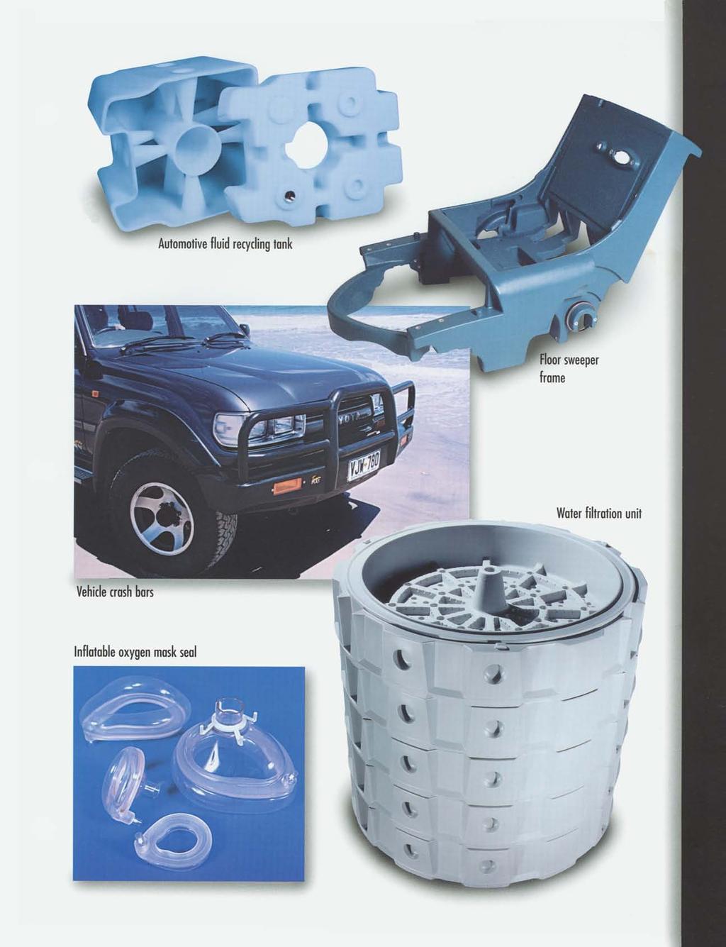
28
Factors to Consider in Plastic Molded Design
 9 Factors to Consider in Plastic Molded Design Table Of Contents Introduction 3 Design 4 1. Draft... 4 2. Surface Finish... 5 3. Witness Lines... 6 4. Wall Thickness... 6 5. Support/Straight Ribs Thickness...
Injection moulding. Introduction. Typical characteristics of injection moulded parts
 Injection moulding Introduction Injection molding is generally used to produce thermoplastic polymers. It consists of heating of thermo plastic materials until it melts and then injecting into the steel
Design Guide: CNC Machining VERSION 3.4
 Design Guide: CNC Machining VERSION 3.4 CNC GUIDE V3.4 Table of Contents Overview...3 Tolerances...4 General Tolerances...4 Part Tolerances...5 Size Limitations...6 Milling...6 Lathe...6 Material Selection...7
Injection Molding from 3D Printed Molds. A study of low-volume production of small LDPE parts FORMLABS WHITE PAPER:
 FORMLABS WHITE PAPER: Injection Molding from 3D Printed Molds A study of low-volume production of small LDPE parts August 25, 2016 Formlabs and Galomb Inc. formlabs.com Table of Contents Introduction........................
Injection Molding Design Guide. Design considerations for rapid manufacturing of plastic parts using injection molding
 Injection Molding Design Guide Design considerations for rapid manufacturing of plastic parts using injection molding Table of contents 1 Injection mold tooling process comparison 3 2 Size considerations
Design Guidelines for Injection Molding
 Design Guidelines for Injection Molding TABLE OF CONTENTS INTRODUCTION TO INJECTION MOLDING A. Where is it used? B. Importance of prototyping C. Types of prototypes INJECTION MOLDING BASICS A. The machine
Moulding. Second Edition. Crawford. Roy J. 4CC%SMITHERS. A Smithers Group Company
 Practical Guide to Rotational Moulding Second Edition Roy J. Crawford Mark P. Kearns 4CC%SMITHERS %))J R A P R A A Smithers Group Company Shawbury, Shrewsbury, Shropshire, SY4 4NR, United Kingdom Telephone:
Processing of Non- Metals Dr. Inderdeep Singh Department of Mechanical and Industrial Engineering Indian Institute of Technology, Roorkee
 Processing of Non- Metals Dr. Inderdeep Singh Department of Mechanical and Industrial Engineering Indian Institute of Technology, Roorkee Module - 4 Plastics: properties and processing Lecture - 7 Rotational
Chapter 1 Sand Casting Processes
 Chapter 1 Sand Casting Processes Sand casting is a mold based net shape manufacturing process in which metal parts are molded by pouring molten metal into a cavity. The mold cavity is created by withdrawing
Better by Design: Guidelines for Designing the Perfect Plated Piece
 MPC Technical Library Better by Design: Guidelines for Designing the Perfect Plated Piece Suggestions, tips and design considerations for enhancing plated part appearance, improving performance and facilitating
Extrusion. Process. The photo below shows a typical thermoplastic extruder.
 Extrusion This process can be compared to squeezing toothpaste from a tube. It is a continuous process used to produce both solid and hollow products that have a constant cross-section. E.g. window frames,
Steel Plate in Oil Rig Blowout Preventer Valves
 Design Problem Steel Plate in Oil Rig Blowout Preventer Valves Introduction Design for Performance Alloy selection Radii and stress reduction Design for Production Mould method Orientation and cores Controlling
Design Guidelines. Pressure Forming
 Design Guidelines For Pressure Forming Plastics Design & Manufacturing Centennial, Colorado Pressure Forming 101 This checklist is a guideline for the design and development of pressure formed parts in
POP FOAM S DESIGN GUIDE 20 Things to Know About Designing with PopFoam:
 POP FOAM S DESIGN GUIDE 20 Things to Know About Designing with PopFoam: 1. Why Use PopFoam 2. The PopFoam Process 3. Guidelines for Draft 4. Parting Line 5. Part Length 6. Undercuts 7. Floating Cores 8.
CHAPTER 5: MOULDING PROCESS
 CHAPTER OUTLINE CHAPTER 5: MOULDING PROCESS 5.1 INTRODUCTION 5.2 INJECTION MOULDING 5.3 COMPRESSION AND TRANSFER MOLDING 5.4 BLOW AND ROTATIONAL MOLDING 5.5 PRODUCT DESIGN CONSIDERATIONS 1 5.1 Introduction
Part Design and Tooling for Rotational Molding : How to Achieve Success in Every Project
 Blue-Reed, LLC Part Design and Tooling for Rotational Molding : How to Achieve Success in Every Project Blue-Reed, LLC 4191 Courtiff Circle Stow, Ohio 44224 www.blue-reed.com Introduction Greg Stout -
TOOLKIT PART 4 MANUFACTURING PROCESSES
 Understanding which manufacturing process has been used to make an object can help you identify its material as different materials are manufactured with different process. Different manufacturing processes
(( Manufacturing )) Fig. (1): Some casting with large or complicated shape manufactured by sand casting.
) Fig. (1): Some casting with large or complicated shape manufactured by sand casting.") (( Manufacturing )) Expendable Mold Casting Processes: Types of expendable mold casting are: 1 ) Sand casting. 2 ) Shell molding. 3 ) Vacuum molding. 4 ) Investment casting. 5 ) Expanded polystyrene process.
(( Manufacturing )) Expendable Mold Casting Processes: Types of expendable mold casting are: 1 ) Sand casting. 2 ) Shell molding. 3 ) Vacuum molding. 4 ) Investment casting. 5 ) Expanded polystyrene process.
3D Printing Technologies for Prototyping and Production
 3D Printing Technologies for Prototyping and Production HOW TO LEVERAGE ADDITIVE MANUFACTURING TO BUILD BETTER PRODUCTS ADDITIVE MANUFACTURING CNC MACHINING INJECTION MOLDING Architects don t build without
Lecture - 05 Thermoforming Processes
 Processing of Polymers and Polymer Composites Dr. Inderdeep Singh Department of Mechanical and Industrial Engineering Indian Institute of Technology, Roorkee Lecture - 05 Thermoforming Processes Namaskar
BMM3643 Manufacturing Processes Metal Casting Processes (Sand Casting)
") BMM3643 Manufacturing Processes Metal Casting Processes (Sand Casting) by Dr Mas Ayu Bt Hassan Faculty of Mechanical Engineering masszee@ump.edu.my Chapter Synopsis This chapter will expose students to
BMM3643 Manufacturing Processes Metal Casting Processes (Sand Casting) by Dr Mas Ayu Bt Hassan Faculty of Mechanical Engineering masszee@ump.edu.my Chapter Synopsis This chapter will expose students to
University of Arizona College of Optical Sciences
 University of Arizona College of Optical Sciences Name: Nachiket Kulkarni Course: OPTI521 Topic Plastic Injection Molding Submitted to Prof. J. Burge Date 1. Introduction In daily life, we come across
Processing of Plastics
 Processing of Plastics Bachelor of Industrial Technology Management with Honours Semester I Session 2013/2014 TOPIC OUTLINE Introduction of Plastics Classification of Plastics Types of Plastic Plastics
Two Categories of Metal Casting Processes
 Two Categories of Metal Casting Processes 1. Expendable mold processes - mold is sacrificed to remove part Advantage: more complex shapes possible Disadvantage: production rates often limited by time to
Drawing. Fig. 1 Drawing
 Drawing Drawing is a metalworking process which uses tensile forces to stretch metal. It is broken up into two types: sheet metal drawing and wire, bar, and tube drawing. The specific definition for sheet
Permanent Mold Casting Processes. Assoc Prof Zainal Abidin Ahmad Department of Manufacturing & Ind. Eng.
 Assoc Prof Zainal Abidin Ahmad Department of Manufacturing & Ind. Eng. Universiti Teknologi Malaysia Permanent Mold Casting Processes Gravity die casting Pressure die casting Low pressure High pressure
Module 3 Selection of Manufacturing Processes
 Module 3 Selection of Manufacturing Processes Lecture 4 Design for Sheet Metal Forming Processes Instructional objectives By the end of this lecture, the student will learn the principles of several sheet
Industrial and Transportation Business DISTRIBUTOR PRODUCT LINE
 Industrial and Transportation Business DISTRIBUTOR PRODUCT LINE 3900 DUCT TAPE 3900 DUCT TAPE MRO (Maintenance and Repair) Construction Trade Shows and Conventions General Industrial Electrical Aerospace
- sprue gate - pinpoint gate - fan gate - tunnel gate
 Moulds for processing of thermosetting moulding compounds 1. Sprue and Runner Systems and Gates Sprues should have either a round cross-section or a rounded trapezoidal construction and must have well-polished
Makrolon Solid Polycarbonate Sheets
 1. General remarks Tools sheets can be machined using the standard tools commonly used for metal and woodworking. We recommend carbide-tipped tools. Above all, it is important to use sharp cutting tools
Metal Casting Processes CHAPTER 11 PART I
 Metal Casting Processes CHAPTER 11 PART I Topics Introduction Sand casting Shell-Mold Casting Expendable Pattern Casting Plaster-Mold Casting Introduction Metal-Casting Processes First casting were made
Introduction to Manufacturing Processes
 Introduction to Manufacturing Processes Products and Manufacturing Product Creation Cycle Design Material Selection Process Selection Manufacture Inspection Feedback Typical product cost breakdown Manufacturing
TECHNICAL NOTE. Rotational Molding Guide
 Ravago Manufacturing Americas 13001 Almeda Road Houston, Texas 77045 713-433-5604 Fax 713-433-9783 TECHNICAL NOTE Rotational Molding Guide Introduction: Rotational molding is a process where plastic materials
AMENDMENTS Manual of STANDARD SPECIFICATIONS. Adopted by Standard Specifications Committee. Amendment. No. 6. Published by
 AMENDMENTS to 2012 Manual of STANDARD SPECIFICATIONS Adopted by Standard Specifications Committee Amendment No. 6 Published by Utah LTAP Center Utah State University 8305 Old Main Hill Logan UT 84322-8205
Ralphs-Pugh Co. I didn t know you did all that!
 Ralphs-Pugh Co. I didn t know you did all that! Ralphs-Pugh Co. The Ralphs-Pugh Company has been keeping industry on the move for over 50 years. We are an innovative supplier that distinguishes itself
Section 914. JOINT AND WATERPROOFING MATERIALS
 914.01 Section 914. JOINT AND WATERPROOFING MATERIALS 914.01. General Requirements. Joint and waterproofing material for use in concrete construction must meet the requirements of this section. 914.02.
All About Die Casting
 All About Die Casting FAQ Introduction Die casting is a versatile process for producing engineered metal parts by forcing molten metal under high pressure into reusable steel molds. These molds, called
PLASTIC FURNITURE MANUFACTURING PROCESS I N T D F U R N I T U R E A N D F I T T I N G S
 PLASTIC FURNITURE MANUFACTURING PROCESS I N T D 3 0 1 F U R N I T U R E A N D F I T T I N G S COMMON MANUFACTURING METHODS FOR PLASTIC FURNITURE 1. MOLDING 1. Extrusion molding 2. Injection molding 3.
Solutions for Signage
 Product Information ACRYLITE LED Solutions for Signage For over 30 years, Evonik Cyro has been the leading acrylic resource for the sign industry. Our trademarked product, ACRYLITE offers outstanding optical
Creating. There is one basic question every customer needs to address when creating custom
 Wire and cable have a very deep history in industry, and remain indispensable for a wide variety of applications today. In our current digitized and online landscape, getting the best wire and cable is
Extruded sheet (FF) #3 Other Methods of Cutting. Technical information. This brief gives advice for:
 #3 Other Methods of Cutting. Technical information. This brief gives advice for:") Technical information Extruded sheet (FF) WARNING: This product can expose you to chemicals including Ethyl acrylate, CAS 140-88-5, which are known to the State of California to cause cancer. For more
Technical information Extruded sheet (FF) WARNING: This product can expose you to chemicals including Ethyl acrylate, CAS 140-88-5, which are known to the State of California to cause cancer. For more
Dicing Through Hard and Brittle Materials in the Micro Electronic Industry By Gideon Levinson, Dicing Tools Product Manager
 Dicing Through Hard and Brittle Materials in the Micro Electronic Industry By Gideon Levinson, Dicing Tools Product Manager A high percentage of micro electronics dicing applications require dicing completely
Fabric Variance Guide
 Fabric Variance Guide Table of Contents Introduction Setting Expectations ColorFastness Stitching Techniques Pattern vs. Railroad Double-Rub Disclaimer Leather Variance Wool Welt Cords Seating Additional
Design and Technology Resistant materials Key words and definitions
 Design and Technology Resistant materials Key words and definitions Word Acrylic Definition a type of thermoplastic, which is hard and can be transparent. Used to make shop signs. Perspex is a trade/brand
Processing of Non-Metals Prof. Dr. Inderdeep Singh Department of Mechanical and Industrial Engineering Indian Institute of Technology, Roorkee
 Processing of Non-Metals Prof. Dr. Inderdeep Singh Department of Mechanical and Industrial Engineering Indian Institute of Technology, Roorkee Module - 4 Plastics: Properties and Processing Lecture - 5
Assmann Corporation of America TANK INSTALLATION AND USE GUIDELINES FOR BULK STORAGE TANKS
 Assmann Corporation of America TANK INSTALLATION AND USE GUIDELINES FOR BULK STORAGE TANKS General Information Assmann polyethylene storage tanks are manufactured to give you the toughest, most reliable
4.1.3: Shell Casting.
 4.1.3: Shell Casting. It is another expandable mold casting type; Shell molding is a casting process in which the mold is a thin shell (typically 9mm) made of sand held together by a thermosetting resin
Investment Casting Design Parameters Guide for Buyer
 Investment Casting Design Parameters Guide for Buyer The following guidelines and technical information outline what an investment casting is capable of offering. It will cover dimensional and structural
Operating & Maintenance Instructions 320 Dome Blowing Unit
 Operating & Maintenance Instructions 320 Dome Blowing Unit Table of Contents 1. On Delivery... 2 2. General Information... 3 3. Dome Blowing Technique... 4 4. Other Shapes... 6 5. Machine Maintenance...
Solidification Process(1) - Metal Casting Chapter 9,10
 - Metal Casting Chapter 9,10") Solidification Process(1) - Metal Casting Chapter 9,10 Seok-min Kim smkim@cau.ac.kr -1- Classification of solidification processes -2- Casting Process in which molten metal flows by gravity or other force
Solidification Process(1) - Metal Casting Chapter 9,10 Seok-min Kim smkim@cau.ac.kr -1- Classification of solidification processes -2- Casting Process in which molten metal flows by gravity or other force
AMTS STANDARD WORKSHOP PRACTICE. Bond Design
 AMTS STANDARD WORKSHOP PRACTICE Reference Number: AMTS_SWP_0027_2008 Date: December 2008 Version: A 1 Contents 1 Technical Terms...3 2 Scope...3 3 Primary References...3 4 Basic...3 4.1 Typical joint types...4
Precision Folding Technology
 Precision Folding Technology Industrial Origami, Inc. Summary Nearly every manufacturing process has experienced dramatic improvements in accuracy and productivity as well as declining cost over the last
FABRIC VARIANCE GUIDE
 FABRIC VARIANCE GUIDE Table of Contents Introduction 3 Setting Expectations Color Fastness Stitching Techniques Pattern vs. Railroad Double-Rub Disclaimer Leather Variance Wool Welt Cords Seating Additional
Types of moulding sand
 casting Types of moulding sand 1. Green sand: Green sand which is also known as natural sand is the mostly used sand in moulding. It is basically the mixture of sand, clay and water. The clay contain
THERMOFORMING DESIGN GUIDELINES
 THERMOFORMING DESIGN GUIDELINES 3808 North Sullivan Road, Building 6 Spokane, Washington, 99216 1-509-924-6631 www.multifab-inc.com (Revision 6-4-2009) MULTIFAB INCORPORATED 3808 North Sullivan Road, Building
BESSEY Training BESSEY Tools North America Alvin Products: Lab Metal, Lab Solvent
 BESSEY Training BESSEY Tools North America Alvin Products: Lab Metal, Lab Solvent Page 1-1 Lab Metal A ready to use, aluminum filled metal repair, filler and patching compound. Easy to use Ready to use
Manufacturing Process - I
 Manufacturing Process - I UNIT III Plastic Processing Prepared By Prof. Shinde Vishal Vasant Assistant Professor Dept. of Mechanical Engg. NDMVP S Karmaveer Baburao Thakare College of Engg. Nashik Contact
wall thinning) can be lower. Wall thinning is determined by part shape and depth of draw. Please contact your 3M representative for more information.
 can be lower. Wall thinning is determined by part shape and depth of draw. Please contact your 3M representative for more information.") 3M Custom Formed Reflectors increase the optical efficiency of a light fixture by using precise reflection optics to raise the lumen output. Each reflector is custom designed to your specifications for
3M Custom Formed Reflectors increase the optical efficiency of a light fixture by using precise reflection optics to raise the lumen output. Each reflector is custom designed to your specifications for
Unit IV Drawing of rods, wires and tubes
 Introduction Unit IV Drawing of rods, wires and tubes Drawing is a process in which the material is pulled through a die by means of a tensile force. Usually the constant cross section is circular (bar,
Fabric Variance Guide
 Fabric Variance Guide Table of Contents Introduction 3 Setting Expectations Color Fastness 4 Stitching Techniques 4 Pattern vs. Railroad 4 Double-Rub Disclaimer 4 Leather Variance 5 Wool 5 Welt Cords 5
WORKING of nidaplast
 nida 8/gb - 03.07.07 Technical Information. 2 WORKING of nidaplast nidaplast is a polypropylene honeycomb covered on both faces with a soft polyester nonwoven fabric. It is available in 2500 x 1200 mm
FUNDAMENTAL MANUFACTURING PROCESSES Plastics Machining & Assembly NARRATION (VO): NARRATION (VO): NARRATION (VO): INCLUDING: METALS,
: NARRATION (VO): NARRATION (VO): INCLUDING: METALS,") Copyright 2002 Society of Manufacturing Engineers --- 1 --- FUNDAMENTAL MANUFACTURING PROCESSES Plastics Machining & Assembly SCENE 1. CG: Plastics Machining white text centered on black SCENE 2. tape
Copyright 2002 Society of Manufacturing Engineers --- 1 --- FUNDAMENTAL MANUFACTURING PROCESSES Plastics Machining & Assembly SCENE 1. CG: Plastics Machining white text centered on black SCENE 2. tape
Refined from crude oil, has relatively low melting point (50-70 C) and relatively brittle. Refined from petroleum, has medium melting range (60 C).
 and relatively brittle. Refined from petroleum, has medium melting range (60 C).") The primary use of waxes in dentistry is to make a pattern of appliances prior to casting as many dental restorations are made by lost-wax technique, in which a pattern is made in wax and put in the mold
The primary use of waxes in dentistry is to make a pattern of appliances prior to casting as many dental restorations are made by lost-wax technique, in which a pattern is made in wax and put in the mold
3 Scotchmate TM. Polyester Reclosable Fasteners. Product Selection Guide April, M Scotchmate Polyester Reclosable Fastener.
 3 Product Selection Guide April, 2003 Products 3M Scotchmate Polyester Reclosable Fastener Plainbacked Products Loop Hook SJ3477 SJ3476 SJ3487FR SJ3486FR Pressure Sensitive Adhesive Products Loop Hook
EVERYTHING TO KNOW ABOUT OVERMOLDED CABLE ASSEMBLIES
 EVERYTHING TO KNOW ABOUT OVERMOLDED CABLE ASSEMBLIES By Brian Morissette, Cable Assembly Product Manager Epec Engineered Technologies Overmolding has dramatically changed the appearance and functionality
Special Casting Process. 1. Permanent mould casting
 Special Casting Process 1. Permanent mould casting A permanent mold casting makes use of a mold or metallic die which is permanent.molten metal is poured into the mold under gravity only and no external
Copyright Notice. HCL Technologies Ltd. All rights reserved. A DEFINITIVE GUIDE TO DESIGN FOR MANUFACTURING SUCCESS
 Copyright Notice HCL Technologies Ltd. All rights reserved. No part of this document (whether in hardcopy or electronic form) may be reproduced, stored in a retrieval system, or transmitted, in any form
Metal Working Processes
 Metal Working Processes Bachelor of Industrial Technology Management with Honours Semester I Session 2013/2014 CLASSIFICATION OF MANUFACTURING PROCESSES TOPIC OUTLINE What is Sheet Metal? Sheet Metalworking
Application Bulletin 240
 Application Bulletin 240 Design Consideration CUSTOM CAPABILITIES Standard PC board fabrication flexibility allows for various component orientations, mounting features, and interconnect schemes. The starting
Interior Design Materials. Glass & Ceramics. Haval Sami Ali
 Interior Design Materials Glass & Ceramics Haval Sami Ali haval.sami@ishik.edu.iq Glass Glass and ceramics are related materials, and glass is sometimes considered as no crystalline ceramic. Clay-based
PRODUCTION TOOLING FOR POLYMER COMPONENTS VIA THE DTM RAPIDSTEEL PROCESS
 PRODUCTION TOOLING FOR POLYMER COMPONENTS VIA THE DTM RAPIDSTEEL PROCESS KW Dalgarno, TD Stewart, & THC Childs School of Mechanical Engineering, University of Leeds, Leeds, LS2 9JT, UK Abstract This paper
DESIGNING THERMOFORMING MOLDS FOR HIGH DENSITY POLYETHYLENE
 PE TIB-82 DESIGNING THERMOFORMING MOLDS FOR HIGH DENSITY POLYETHYLENE INTRODUCTION Advancements in thermoforming high density polyethylene (HDPE) have been significant in recent years, including important
Hot Melt Adhesives Jet-melt & Hot Melt Spray. Distributed By:
 Hot Melt Adhesives Jet-melt & Hot Melt Spray Distributed By: www.wilcox-slidders.com 3M Scotch-Weld Hot Melt Adhesives and Applicators The 3M systems approach to help you improve productivity and lower
Casting Processes. ver. 2
 Casting Processes ver. 2 1 Types of Parts Made Engine blocks Pipes Jewelry Fire hydrants 2 Complex, 3-D shapes Near net shape Low scrap Relatively quick process Intricate shapes Large hollow shapes No
Design for machining
 Design for machining Machining processes are material removal processes which are a family of shaping operation in which excess or undesired material is removed from the work piece finally remaining with
Hand Torch or Flame Brazing Principles
 Hand Torch or Flame Brazing Principles Introduction Hand-torch brazing is inexpensive and flexible, making it ideally suited to small production batches or production runs involving differing components.
Manufacturing Processes (continued)
") Manufacturing (continued) Machining Some other processes Material compatibilities Process (shape) capabilities Manufacturing costs Correct pg 142, question 34i should read Fig 6.18 question 34j should
Manufacturing (continued) Machining Some other processes Material compatibilities Process (shape) capabilities Manufacturing costs Correct pg 142, question 34i should read Fig 6.18 question 34j should
Technical Guide for Glass Cutting Section 1 - Two Basic Types of Cutting
 Section 1 - Two Basic Types of Cutting Part 2 Pressure Cutting Basic Principles of Pressure Cutting This portion of Part 2 deals with those aspects of the basic principles of glass cutting that are common
Think like a machinist when creating solid models
 Think like a machinist when creating solid models Article by Milton Florest President Tooling Research Inc. 81 Diamond St. Walpole, MA 02081 Website www.tooling research.com 508 668 1950 Since the introduction
LGCSE DESIGN AND TECHNOLOGY 0189 REPORT FOR TEACHERS
 LGCSE DESIGN AND TECHNOLOGY 0189 REPORT FOR TEACHERS The 2016 Design and technology Paper was composed of 16 questions of which 10 of them formed part A and were compulsory and contributed 28 marks. These
Welding Engineering Dr. D. K. Dwivedi Department of Mechanical & Industrial Engineering Indian Institute of Technology, Roorkee
 Welding Engineering Dr. D. K. Dwivedi Department of Mechanical & Industrial Engineering Indian Institute of Technology, Roorkee Module - 4 Arc Welding Processes Lecture - 8 Brazing, Soldering & Braze Welding
ROOP LAL Unit-6 Lathe (Turning) Mechanical Engineering Department
 Mechanical Engineering Department") Notes: Lathe (Turning) Basic Mechanical Engineering (Part B) 1 Introduction: In previous Lecture 2, we have seen that with the help of forging and casting processes, we can manufacture machine parts of
Notes: Lathe (Turning) Basic Mechanical Engineering (Part B) 1 Introduction: In previous Lecture 2, we have seen that with the help of forging and casting processes, we can manufacture machine parts of
CARL HANSER VERLAG. Herbert Rees. Mold Engineering 2nd edition
 CARL HANSER VERLAG Herbert Rees Mold Engineering 2nd edition 3-446-21659-6 www.hanser.de 3 1 Introduction to Mold Engineering Mold Engineering deals with injection molds for thermoplastic molding materials.
Preforming & Preheating
 PLASTICS ENGINEERING COMPANY SHEBOYGAN, WISCONSIN 53082-0758 U.S.A 3518 LAKESHORE ROAD POST OFFICE BOX 758 PHONE 920-458 - 2121 F A X 920-458 - 1923 Preforming & Preheating When compression or transfer
Manufacturing Processes - I Dr. D. B. Karunakar Department of Mechanical and Industrial Engineering Indian Institute of Technology, Roorkee
 Manufacturing Processes - I Dr. D. B. Karunakar Department of Mechanical and Industrial Engineering Indian Institute of Technology, Roorkee Lecture - 4 Module 2 Metal Casting Good morning, Metal casting,
METAL FABRICATION SECTION 8: METAL FABRICATION SCOPE MATERIAL.
 METAL FABRICATION SCOPE This specification applies to all metal intended to be rubber lined. Metals furnished must conform to this specification with respect to suitability for rubber lining or covering.
1. There is a variety of casting processes. Many casting process characteristics are similar
 CHAPTER 14 Expendable-Mold Casting Processes Review Questions 1. There is a variety of casting processes. Many casting process characteristics are similar but each has distinct characteristics that determine
AESOP 3D Imaging Workshop Educational 3D Models
 AESOP 3D Imaging Workshop Educational 3D Models Dennis Kriel Dennis Kriel from 3D makerspace http://www.up.ac.za/en/news/post_2062883-south-africas-first-librarymakerspace-opens-at-the-university-of-pretoria
Taking MIM Tooling To the Next Level. Originally published in The American Mold Builder Magazine, February 2014
 Taking MIM Tooling To the Next Level Originally published in The American Mold Builder Magazine, February 2014 1 Metal injection molding (MIM) merges two established technologies, plastic injection molding
NOTE: This product can be used externally if UV Guard is added (BY REQUEST ONLY).
.") Product Description PHOENIX PAINTS MAXICOAT 100 is a 2 Pack Water-Dispersed Top Coat which not only exhibits the physical and chemical strengths of epoxy, but also the safety and convenience of water as
Product Description PHOENIX PAINTS MAXICOAT 100 is a 2 Pack Water-Dispersed Top Coat which not only exhibits the physical and chemical strengths of epoxy, but also the safety and convenience of water as
Tech Notes. GEL COAT FLEXIBILITY The Flex Strip Test. INTERPLASTIC CORPORATION Thermoset Resins Divison ISSUE 1
 INTERPLASTIC CORPORATION Thermoset Resins Divison ISSUE Tech Notes GEL COAT FLEXIBILITY The Flex Strip Test Issue Date: /4/00 Document ID: TN-TS-0A 00 Interplastic Corporation Gel Coat Flexibility: The
Profiting with Wire EDM
 3 Profiting with Wire EDM Users of Wire EDM 55 Parts made with the wire EDM process are used for machining conductive materials for medicine, chemical, electronics, oil and gas, die and mold, fabrication,
Adhesive. Choosing between Adhesives and Ultrasonic Welding. Join parts faster, smarter, and under budget with TiPS from leading suppliers
 Adhesive www.designworldonline.com A Supplement to Design World Choosing between Adhesives and Ultrasonic Welding Join parts faster, smarter, and under budget with TiPS from leading suppliers A d h e s
Kitchen Stainer to filter Vitrolite
 Vitrolite is a photocurable polymer resin for use in SLA or DLP printers. After firing, Vitrolite is a glass ceramic with high strength, low porosity/high density and thermal shock tolerance. Vitrolite
Fasteners. Metal Fasteners, Joining, and Adhesives. Bolts. Metal Fasteners, Joining, and Adhesives
 Metal Fasteners, Joining, and Adhesives Fasteners Metal assemblies are often held together with fasteners, hardware devices that mechanically join or affix two or more objects together. Assembling with
White paper. Exploring metal finishing methods for 3D-printed parts
 01 Exploring metal finishing methods for 3D-printed parts 02 Overview Method tested Centrifugal disc Centrifugal barrel Media blasting Almost all metal parts whether forged, stamped, cast, machined or
DIRECT METAL LASER SINTERING DESIGN GUIDE
 DIRECT METAL LASER SINTERING DESIGN GUIDE www.nextlinemfg.com TABLE OF CONTENTS Introduction... 2 What is DMLS?... 2 What is Additive Manufacturing?... 2 Typical Component of a DMLS Machine... 2 Typical
SHAPED BY INNOVATION.
 SHAPED BY INNOVATION www.fishercast.com Engineering the best value At FisherCast Global, we are committed to engineering cost-effective, innovative manufacturing solutions for your small component production
Porcelite is ideal for objects requiring high resolution details. It s capable of printing at 25 micron layer thickness.
 fa is a UV-curable porcelain resin suitable for 3D printers that utilize SLA, DLP or CLIP technologies with UV wavelengths between 350-405 nm. Porcelite is ideal for objects requiring high resolution details.
3D PRINTER MATERIALS GUIDE
 3D PRINTER MATERIALS GUIDE The two primary technologies used for desktop 3D printing are fused deposition modeling () and stereolithography (). For those new to 3D printing, technology feeds melted plastic