C A R T E R W A T K I N S A S S O C I A T E S A R C H I T E C T S, I N C.
|
|
|
- Lora Houston
- 6 years ago
- Views:
Transcription
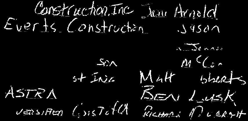
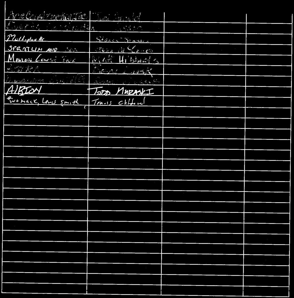
1 C A R T E R W A T K I N S A S S O C I A T E S A R C H I T E C T S, I N C. DATE: December 20, 2017 RE: GORDON COUNTY ANIMAL SHELTER ADDENDUM #2 The following information provided in this Addendum shall supersede all information provided in the Construction Documents in regard to the affected items. This Addendum shall become part of the Construction Documents for the above project and shall be acknowledged by each bidder on the bid form. Item 1: Item 2: Item 3: Item 4: Item 5: Item 6: Item 7: Item 8: Item 9: Item 10: Item 11: Item 12: Item 13: Please see updated C1.0, attached, which clarifies existing and proposed contractors. All permit fees, utility tap fees, and impact fees will be waived on this project. Attached, please find the Pre-bid Attendee list of Contractors, Sub-contractors, and suppliers Geo-technical testing, if needed, will be contracted by the County. Concrete testing is to be by the Contractor. Guillotine door size to be industry standard as dictated by kennel manufacturer. Contractor to provide complete shop drawings with layout and details for approval prior to ordering kennels. Concrete mixing for vertical CMU cell and bond beams can occur onsite. Existing water line to be connected to new building. Contractor shall be responsible for determining location and for making complete connections. Grinder and Sand/sediment trap is shown on P-1. Glass in CMU wall above kennels to be 1 insulated, Lo-E, untinted. Disregard note for 2-hour rating on Floor Plan. Intersection of drywall wall to ceiling to have a ½ x 4 closure piece of Hardi-Plank installed after fire caulking installed. Sewer line to be schedule 80 PVC to road. P o s t O f f i c e B o x M o n r o e, G e o r g i a / T e l e p h o n e / F a c s i mi l e
2 Item 14: Item 15: Item 16: Item 17: Storage building(s) to be relocated just off of paved area. Note 7 on S1.0 to be changed to allow all penetrations to be schedule 80 pvc. Attic smoke compartment to consist of one layer of 5/8 type x gypsum board on one side of truss with all edges and joints sealed with fire caulking. Provide 36 x 60 access door in wall with 20-minute rated door with lever handle passage lockset and closer. Rated ceilings to be two layers of gypsum board on furring strips with fire caulking at all penetrations. (Confirm this with local Fire Marshal as many jurisdictions have different interpretations or this requirement). Item 18: Attached is Section Specification for Pre-cast Concrete. 4 sill (wainscot line) to be 4 x 9 (1 projection from CMU). Headers to be 9 high by 8 deep, sills to be 4 x9 with top exterior surface beveled ½ inch for a distance of 4 min from top outside face. Item 19: Epoxy Floor coating to be Sherwin Williams Armoseal 8100 Epoxy Floor Coating. See manufacturers instructions for surface preparation and installation execution. END OF ADDENDUM P o s t O f f i c e B o x M o n r o e, G e o r g i a / T e l e p h o n e / F a c s i mi l e


3

4 Z:\SHARED CAD\PROJECTS\GORDON COUNTY ANIMAL SHELTER\Gordon County Animal Shelter\Sheets\C 1.0 SITE PLAN.dwg Jan REVISIONS Number Date: Remarks: Number Date: Remarks: X N/A CONSULTANTS EXISTING TREE LINE RE-GRADE AT TREE LINE TO PROVIDE NEW SWALE - CONNECT TO EXISTING EXISTING WATER LINE VERIFY LOCATION 22'-0" CONTRACTOR TO RUN ELECTRICAL SERVICE UNDERGROUND IN CONDUIT FROM ELECTRICAL ROOM TO POWER POLL & CONNECT TO TRANSFORMER. 1 SITE PLAN 1/16" = 1'-0" PROVIDE 4-4" PVC CONDUITS TO POLE 5'-0" 5'-0" ' RELOCATE STORAGE BUILDINGS TO OWNER SPECIFIED LOCATION 4"ELECTRIC 4"ELECTRIC COM 4" PHONE 4" DATA 4" SPARE 8'-0" 4" 22'-0" 5'-0" 90'-0" ' FIN. FL. ELEV ' 19'-0" 54'-0" 6' HIGH CHAIN LINK FENCE - SEE SPECIFICATIONS ' 4' WIDE WALK \GATE - TYP. 22'-0" 32'-0" 19'-0" R6'-0" R12'-0" 5'-0" FILL R6'-0" 18'-0" 10'-0" HC 18'-0" 18'-0" 18'-0" TYP. HC ' CARTER WATKINS ASSOCIATES ARCHITECTS, INC. POST OFFICE BOX EAST WASHINGTON STREET MONROE, GEORGIA Fax: 770/ @carterwatkins.com EXISTING 9'-0" TYP. 24'-0" DEMO ALL ASPHALT FROM THIS POINT NEW ASPHALT GRINDER C E M E T E R Y DEMO ALL ASPHALT FROM THIS POINT LIMIT OF ASPHALT AT THIS LOCATION 3 0 POLE MOUNTED TRANSFORMER SET ON POLL BY POWER COMPANY SAND & SEDIMENT TRAP MAN HOLE DEMOLISH ALL OF EXISTING BUILDING PAD SEAL T STA EO CERTIFICAT F GEORG BENJAMIN MERCER CARTER IA REGISTERED ARCHITECT E. NO NEW SANITARY SEWER LINE - CONNECT TO R.O.W. ALLOW FOR 4 MAN HOLES - DISTANCE TO ROAD 435 FT.- GORDON COUNTY ANIMAL SHELTER GORDON COUNTY, GEORGIA NOTE - BASE BID TO INCLUDE ALL SITE WORK. PROVIDE AN ALTERNATE DEDUCT TO PROVIDE ONLY BUILDING PAD PREPARATION & STUBBING UTILITIES OUT 5 FEET PERIMETER SIDEWALK FENCING TO BE A SEPARATE DEDUCT ALT. ITEM. REFER TO PROJECT MANUAL FOR ALL ALTERNATES. N 1 16 " =1'-0" SHEET TITLE: SITE PLAN PRINTED: NUMBER: C 1.0 This Document is the property of Carter Watkins Associates. PRINTED DATE: Reproduction of any kind is prohibited under Federal Copyright Laws. 01/10/18
5 SECTION PRECAST ARCHITECTURAL CONCRETE PART 1 - GENERAL 1.1 RELATED DOCUMENTS A. Drawings and general provisions of the Contract, including General and Supplementary Conditions and Division 01 Specification Sections, apply to this Section. 1.2 SUMMARY A. This Section includes the following: B. 1. Sills, Bands, Caps and Wainscoting C. Related Sections include the following: 1. Division 03 Section "Cast-In-Place Concrete" for installing connection anchors in concrete. 2. Division 04 Section Unit Masonry for exterior brick veneer 3. Division 05 Section "Structural Steel Framing" for furnishing and installing connections attached to structural-steel framing. 4. Division 05 Section "Metal Fabrications" for kickers and other miscellaneous steel shapes. 5. Division 07 Section Sheet Metal Flashing and Trims 1.3 DEFINTION A. Design Reference Sample: Sample of approved architectural precast concrete color, finish and texture, provided by Northwest Precast and preapproved by Architect. 1.4 PERFORMANCE REQUIREMENTS A. Structural Performance: Provide architectural precast concrete units and connections capable of withstanding the following design loads within limits and under conditions indicated: 1. Loads: As indicated on structural drawings. 1.5 ACTION SUBMITTALS A. Product Data: For each type of product indicated. B. Design Mixtures: For each precast concrete mixture. Include compressive strength and water-absorption tests. C. Shop Drawings: Detail fabrication and installation of architectural precast concrete units. Indicate locations, plans, elevations, dimensions, shapes, and cross sections of each unit. Indicate joints, reveals, and extent and location of each surface finish. Indicate details at building corners. PRECAST ARCHITECTURAL CONCRETE
6 1. Indicate separate face and backup mixture locations and thicknesses. 2. Indicate welded connections by AWS standard symbols. Detail loose and cast-in hardware and connections. 3. Indicate locations, tolerances, and details of anchorage devices to be embedded in or attached to structure or other construction. 4. Indicate locations, extent, and treatment of dry joints if two-stage casting is proposed. 5. Include plans and elevations showing unit location and sequence of erection for special conditions. 6. Indicate location of each architectural precast concrete unit by same identification mark placed on panel. 7. Indicate relationship of architectural precast concrete units to adjacent materials. 8. Indicate locations and details of brick units, including corner units and special shapes, and joint treatment. 9. Indicate locations and details of stone facings, anchors, and joint widths. 10. Design Modifications: If design modifications are proposed to meet performance requirements and field conditions, submit design calculations and Shop Drawings. Do not adversely affect the appearance, durability, or strength of units when modifying details or materials and maintain the general design concept. D. Samples: For each type of finish indicated on exposed surfaces of architectural precast concrete units, in sets of 3, illustrating full range of finish, color, and texture variations expected; approximately 12 by 12 by 2-inches. 1. When other faces of precast concrete unit are exposed, include Samples illustrating workmanship, color, and texture of backup concrete as well as facing concrete. 1.6 INFORMATIONAL SUBMITTALS A. Qualification Data: For Installer, fabricator and testing agency. B. Welding certificates. C. Material Certificates: For the following items, signed by manufacturers: 1. Cementitious materials. 2. Reinforcing materials. 3. Admixtures. 4. Bearing pads. 5. Structural-steel shapes and hollow structural sections. 6. Stone anchors. D. Material Test Reports: For aggregates. E. Source quality-control test reports. F. Field quality-control test and special inspection reports. 1.7 QUALITY ASSURANCE A. Fabricator qualifications: The bidding firm shall participate in the Architectural Precast Association (APA) Plant Certification Program of Architectural Precast Concrete Products and is designated as an APA- Certified Plant. The bidding firm responsibility includes preparing of shop drawings and comprehensive engineering analysis by a qualified professional engineer. They shall demonstrate a minimum of 5 years experience in producing units similar to those required for this project. B. Installer Qualifications: Installer shall demonstrate a record of at least five years of successful installation of precast units similar to those required for this project. PRECAST ARCHITECTURAL CONCRETE
7 C. Fabricator Qualifications: A firm that assumes responsibility for engineering architectural precast concrete units to comply with performance requirements. This responsibility includes preparation of Shop Drawings and comprehensive engineering analysis by a qualified professional engineer. D. Testing Agency Qualifications: An independent testing agency acceptable to authorities having jurisdiction, qualified according to ASTM C 1077 and ASTM E 329 for testing indicated. E. Quality-Control Standard: For manufacturing procedures and testing requirements, quality-control recommendations, and dimensional tolerances for types of units required, comply with PCI MNL 117, "Manual for Quality Control for Plants and Production of Architectural Precast Concrete Products." F. Welding: Qualify procedures and personnel according to AWS D1.1/D.1.1M, "Structural Welding Code - Steel"; and AWS D1.4, "Structural Welding Code - Reinforcing Steel." G. Sample Panels: After sample approval and before fabricating architectural precast concrete units, produce a minimum of 2 sample panels approximately 16 sq. ft. in area for review by Architect. Incorporate full-scale details of architectural features, finishes, textures, and transitions in sample panels. 1. Locate panels where indicated or, if not indicated, as directed by Architect. 2. Damage part of an exposed-face surface for each finish, color, and texture, and demonstrate adequacy of repair techniques proposed for repair of surface blemishes. 3. After acceptance of repair technique, maintain one sample panel at manufacturer's plant and one at Project site in an undisturbed condition as a standard for judging the completed Work. 4. Demolish and remove sample panels when directed. H. Mockups: After sample panel approval but before production of architectural precast concrete units, construct full-sized mockups to verify selections made under sample submittals and to demonstrate aesthetic effects and set quality standards for materials and execution. 1. Build mockup as indicated on Drawings of architectural precast concrete complete with anchors, connections, flashings, and joint fillers. 2. Approved mockups may become part of the completed Work if undamaged at time of Substantial Completion. 3. Approval of mockups does not constitute approval of deviations from the Contract Documents unless such deviations are specifically approved by Architect in writing. I. Preconstruction Testing Mockup: Provide a full-size mockup of architectural precast concrete indicated on Drawings for preconstruction testing. Provide confirmation of precast testing information. 1. Build preconstruction testing mockup size and design determined as indicated on Drawings including aluminum framing, glass, sealants. Architectural precast concrete mock-up to be complete with anchors, connections, flashings, and joint fillers. Mockup color and finish to match the design reference sample. 2. Build preconstruction testing mockup at testing agency facility. J. Pre-installation Conference: Conduct conference at Project site to comply with requirements in Division 01 Section "Project Management and Coordination." 1.8 DELIVERY, STORAGE, AND HANDLING A. Deliver architectural precast concrete units in such quantities and at such times to limit unloading units temporarily on the ground. B. Support units during shipment on non-staining shock-absorbing material. C. Store units with adequate dunnage and bracing and protect units to prevent contact with soil, to prevent staining, and to prevent cracking, distortion, warping or other physical damage. PRECAST ARCHITECTURAL CONCRETE
8 D. Place stored units so identification marks are clearly visible, and units can be inspected. E. Handle and transport units in a position consistent with their shape and design in order to avoid excessive stresses which would cause cracking or damage. F. Lift and support units only at designated points shown on Shop Drawings. 1.9 SEQUENCING A. Furnish loose connection hardware and anchorage items to be embedded in or attached to other construction without delaying the Work. Provide locations, setting diagrams, templates, instructions, and directions, as required, for installation. PART 2 - PRODUCTS 2.1 MOLD MATERIALS A. Molds: Rigid, dimensionally stable, non-absorptive material, warp and buckle free, that will provide continuous and true precast concrete surfaces within fabrication tolerances indicated; nonreactive with concrete and suitable for producing required finishes. 1. Mold-Release Agent: Commercially produced liquid-release agent that will not bond with, stain or adversely affect precast concrete surfaces and will not impair subsequent surface or joint treatments of precast concrete. B. Form Liners: Units of face design, texture, arrangement, and configuration to match design reference sample. Furnish with manufacturer's recommended liquid-release agent that will not bond with, stain, or adversely affect precast concrete surfaces and will not impair subsequent surface or joint treatments of precast concrete. 2.2 REINFORCING MATERIALS A. Reinforcing Bars: ASTM A 615/A 615M, Grade 60, deformed. B. Low-Alloy-Steel Reinforcing Bars: ASTM A 615/A 615M, Grade 60, deformed. C. Steel Bar Mats: ASTM A 184/A 184M, fabricated from ASTM A 615/A 615M, Grade 60,, deformed bars, assembled with clips. D. Plain-Steel Welded Wire Reinforcement: ASTM A 185, fabricated from as-drawn steel wire into flat sheets. E. Deformed-Steel Welded Wire Reinforcement: ASTM A 497/A 497M, flat sheet. F. Supports: Suspend reinforcement from back of mold or use bolsters, chairs, spacers, and other devices for spacing, supporting, and fastening reinforcing bars and welded wire reinforcement in place according to PCI MNL CONCRETE MATERIALS A. Portland Cement: ASTM C 150, Type I or Type III, gray or white based on architects selection. Use only one brand type and color from same mill. PRECAST ARCHITECTURAL CONCRETE
9 B. Supplementary Cementitious Materials: 1. Fly Ash: ASTM C 618, Class C or F, with maximum loss on ignition of 3 percent. 2. Metakaolin Admixture: ASTM C 618, Class N. 3. Silica Fume Admixture: ASTM C 1240, with optional chemical and physical requirement. 4. Ground Granulated Blast-Furnace Slag: ASTM C 989, Grade 100 or 120. C. Normal-Weight Aggregates: Except as modified by PCI MNL 117, ASTM C 33, with coarse aggregates complying with Class 5S. Stockpile fine and coarse aggregates for each type of exposed finish from a single source (pit or quarry) for Project to match design reference sample mix design. 1. Face-Mixture-Coarse Aggregates: Selected, hard, and durable; free of material that reacts with cement or causes staining; to match design mix of the design reference. a. Gradation: To match design reference sample. 2. Face-Mixture-Fine Aggregates: Selected, natural or manufactured sand of same material as coarse aggregate, to match design reference sample, unless otherwise approved by the Architect. D. Coloring Admixture: ASTM C 979, synthetic or natural mineral-oxide pigments or colored water-reducing admixtures, temperature stable, and non-fading. E. Water: Potable; free from deleterious material that may affect color stability, setting, or strength of concrete and complying with chemical limits of PCI MNL 117. F. Air-Entraining Admixture: ASTM C 260, certified by manufacturer to be compatible with other required admixtures. G. Chemical Admixtures: Certified by manufacturer to be compatible with other admixtures and to not contain calcium chloride or more than 0.15 percent chloride ions or other salts by weight of admixture. 1. Water-Reducing Admixtures: ASTM C 494/C 494M, Type A. 2. Retarding Admixture: ASTM C 494/C 494M, Type B. 3. Water-Reducing and Retarding Admixture: ASTM C 494/C 494M, Type D. 4. Water-Reducing and Accelerating Admixture: ASTM C 494/C 494M, Type E. 5. High-Range, Water-Reducing Admixture: ASTM C 494/C 494M, Type F. 6. High-Range, Water-Reducing and Retarding Admixture: ASTM C 494/C 494M, Type G. 7. Plasticizing and Retarding Admixture: ASTM C 1017/C 1017 M. 2.4 STEEL CONNECTION MATERIALS A. As indicated on drawings. B. Carbon-Steel Shapes and Plates: ASTM A 36/A 36M. C. Carbon-Steel-Headed Studs: ASTM A 108, AISI 1018 through AISI 1020, cold finished, AWS D1.1/D1.1M, Type A or B, with arc shields and with minimum mechanical properties of PCI MNL 117, Table D. Carbon-Steel Plate: ASTM A 283/A 283M. E. Malleable Iron Castings: ASTM A 47/A 47M. F. Carbon-Steel Castings: ASTM A 27/A 27M, Grade G. High-Strength, Low-Alloy Structural Steel: ASTM A 572/A 572M. H. Carbon-Steel Structural Tubing: ASTM A 500, Grade B. PRECAST ARCHITECTURAL CONCRETE
10 I. Wrought Carbon-Steel Bars: ASTM A 675/A 675M, Grade 65. J. Deformed-Steel Wire or Bar Anchors: ASTM A 496 or ASTM A 706/A 706M. K. Carbon-Steel Bolts and Studs: ASTM A 307, Grade; carbon-steel, hex-head bolts and studs; carbon-steel nuts, ASTM A 563; and flat, unhardened steel washers, ASTM F 844. L. High-Strength Bolts and Nuts: ASTM A 325, Type 1, heavy hex steel structural bolts; heavy hex carbon-steel nuts, ASTM A 563; and hardened carbon-steel washers, ASTM F 436. M. Shop-Primed Finish: Prepare surfaces of non-galvanized steel items, except those surfaces to be embedded in concrete, according to requirements in SSPC-SP 3 and shop-apply [lead- and chromate-free, rust-inhibitive primer, complying with performance requirements in MPI 79, SSPC-Paint 25 according to SSPC-PA 1. N. Welding Electrodes: Comply with AWS standards. 2.5 HOT-DIP GALVINIZED COATED CONNECTION MATERIALS A. As indicated on drawings. B. Zinc-Coated Finish: All items indicated for galvanizing, apply zinc coating by hot-dip process according to ASTM A 123/A 123M. 1. For steel shapes, plates, and tubing to be galvanized, limit silicon content of steel to less than 0.03 percent or to between 0.15 and 0.25 percent or limit sum of silicon and 2.5 times phosphorous content to 0.09 percent. 2. Galvanizing Repair Paint: High-zinc-dust-content paint with dry film containing not less than 94 percent zinc dust by weight, and complying with DOD-P-21035B or SSPC-Paint STAINLESS-STEEL CONNECTION MATERIALS A. As indicated on drawings. B. Stainless-Steel Plate: ASTM A 666, Type 304, of grade suitable for application. C. Stainless-Steel Bolts and Studs: ASTM F 593, Alloy 304 or 316, hex-head bolts and studs; stainless-steel nuts; and flat, stainless-steel washers. 1. Lubricate threaded parts of stainless-steel bolts with an anti-seize thread lubricant during assembly. D. Stainless-Steel-Headed Studs: ASTM A 276, with minimum mechanical properties of PCI MNL 117, Table BEARING PADS A. Provide one of the following bearing pads for architectural precast concrete units[ as recommended by precast fabricator for application: 1. Elastomeric Pads: AASHTO M 251, plain, vulcanized, 100 percent polychloroprene (neoprene) elastomer, molded to size or cut from a molded sheet, Type A durometer hardness of 50 to 70, ASTM D 2240, minimum tensile strength 2250 psi, ASTM D Random-Oriented, Fiber-Reinforced Elastomeric Pads: Preformed, randomly oriented synthetic fibers set in elastomer. Type A durometer hardness of 70 to 90, ASTM D 2240; capable of supporting a compressive stress of 3000 psi with no cracking, splitting, or delaminating in the internal portions of pad. Test one specimen for every 200 pads used in Project. PRECAST ARCHITECTURAL CONCRETE
11 3. Cotton-Duck-Fabric-Reinforced Elastomeric Pads: Preformed, horizontally layered cotton-duck fabric bonded to an elastomer; Type A durometer hardness of 80 to 100, ASTM D 2240; complying with AASHTO's "AASHTO Load and Resistance Factor Design (LRFD) Bridge Design Specifications, Division II, Section , or with MIL-C-882E. 4. Frictionless Pads: Tetrafluoroethylene (Teflon), glass-fiber reinforced, bonded to stainless or mild-steel plate, of type required for in-service stress. 5. High-Density Plastic: Multimonomer, non-leaching, plastic strip. 2.8 ACCESSORIES A. Reglets: Specified in Division 07 Section "Sheet Metal Flashing And Trim." B. Precast Accessories: Provide clips, hangers, plastic or steel shims, and other accessories required to install architectural precast concrete units. 2.9 GROUT MATERIALS A. Sand-Cement Grout: Portland cement, ASTM C 150, Type I, and clean, natural sand, ASTM C 144 or ASTM C 404. Mix at ratio of 1 part cement to 2-1/2 parts sand, by volume, with minimum water required for placement and hydration. B. Nonmetallic, Non-shrink Grout: Premixed, nonmetallic, noncorrosive, non-staining grout containing selected silica sands, Portland cement, shrinkage-compensating agents, plasticizing and water-reducing agents, complying with ASTM C 1107, Grade A for dry pack and Grades B and C for flowable grout and of consistency suitable for application within a 30-minute working time. C. Epoxy-Resin Grout: Two-component, mineral-filled epoxy resin; ASTM C 881/C 881M, of type, grade, and class to suit requirements. D. Bond Breaker: [Preformed, compressible, resilient, non-staining, non-waxing, closed-cell polyethylene foam pad, nonabsorbent to liquid and gas, 1/8 inch thick Polyethylene sheet, ASTM D 4397, 6 to 10 mils thick CONCRETE MIXTURES A. Prepare design mixtures for each type of precast concrete required. 1. Limit use of fly ash and silica fume to 20 percent of Portland cement by weight; limit metakaolin and silica fume to 10 percent of Portland cement by weight. B. Design mixtures may be prepared by a qualified independent testing agency or by qualified precast plant personnel at architectural precast concrete fabricator's option. C. Limit water-soluble chloride ions to maximum percentage by weight of cement permitted by ACI 318 or PCI MNL 117 when tested according to ASTM C 1218/C 1218M. D. Normal-Weight Concrete Mixtures: Proportion full-depth mixtures, at fabricator's option by either laboratory trial batch or field test data methods according to ACI 211.1, with materials to be used on Project, to provide normal-weight concrete with the following properties: 1. Compressive Strength (28 Days): 5000 psi minimum. 2. Maximum Water-Cementitious Materials Ratio: E. Water Absorption: 6 percent by weight or 14 percent by volume, tested according to PCI MNL Compressive Strength (28 Days): 5000 psi. PRECAST ARCHITECTURAL CONCRETE
12 2. Unit Weight: Calculated equilibrium unit weight of 115 lb/cu. ft., plus or minus 3 lb/cu. ft., according to ASTM C 567. F. Add air-entraining admixture at manufacturer's prescribed rate to result in concrete at point of placement having an air content complying with PCI MNL 117. G. When included in design mixtures, add other admixtures to concrete mixtures according to manufacturer's written instructions MOLD FABRICATION A. Molds: Accurately construct molds, mortar tight, of sufficient strength to withstand pressures due to concreteplacement operations and temperature changes. Coat contact surfaces of molds with release agent before reinforcement is placed. Avoid contamination of reinforcement s by release agent. 1. Place form liners accurately to provide finished surface texture indicated. Provide solid backing and supports to maintain stability of liners during concrete placement. Coat form liner with form-release agent. B. Maintain molds to provide completed architectural precast concrete units of shapes, lines, and dimensions indicated, within fabrication tolerances specified. 1. Form joints are not permitted on faces exposed to view in the finished work. 2. Edge and Corner Treatment: Uniformly chamfered and/or radiused FABRICATION A. Cast-in Anchors, Inserts, Plates, Angles, and Other Anchorage Hardware: Fabricate anchorage hardware with sufficient anchorage and embedment to comply with design requirements. Locate anchorage hardware where it does not affect position of main reinforcement or concrete placement. 1. Weld-headed studs and deformed bar anchors used for anchorage according to AWS D1.1/D1.1M and AWS C5.4, "Recommended Practices for Stud Welding." B. Furnish loose hardware items including steel plates, clip angles, seat angles, anchors, dowels, cramps, hangers, and other hardware shapes for securing architectural precast concrete units to supporting and adjacent construction. C. Cast-in reglets, slots, holes, and other accessories in architectural precast concrete units as indicated on the Contract Drawings. D. Cast-in openings in any dimension. Do not drill or cut openings without Architect's approval. E. Reinforcement: Comply with recommendations in PCI MNL 117 for fabricating, placing, and supporting reinforcement. 1. Clean reinforcement of loose rust and mill scale, earth, and other materials that reduce or destroy the bond with concrete. When damage to epoxy-coated reinforcing exceeds limits specified in ASTM A 775/A 775M, repair with patching material compatible with coating material and epoxy coat bar ends after cutting. 2. Accurately position, support, and secure reinforcement against displacement during concrete-placement and consolidation operations. Completely conceal support devices to prevent exposure on finished surfaces. 3. Place reinforcement to maintain at least 3/4-inch -minimum coverage. Arrange, space, and securely tie bars and bar supports to hold reinforcement in position while placing concrete. Direct wire tie ends away from finished, exposed concrete surfaces. PRECAST ARCHITECTURAL CONCRETE
13 4. Place reinforcing steel to maintain at least 3/4-inch -minimum concrete cover. Increase cover requirements for reinforcing steel to 1-1/2-inches when units are exposed to corrosive environment or severe exposure conditions. Arrange, space, and securely tie bars and bar supports to hold reinforcement in position while placing concrete. Direct wire tie ends away from finished, exposed concrete surfaces. 5. Install welded wire fabric in lengths as long as practicable. Lap adjoining pieces at least one full mesh spacing and wire tie laps, where required by design. Offset laps of adjoining widths to prevent continuous laps in either direction. F. Reinforce architectural precast concrete units to resist handling, transportation, and erection stresses. G. Comply with requirements in PCI MNL 117 and requirements in this Section for measuring, mixing, transporting, and placing concrete. After concrete batching, no additional water may be added. H. Place face mixture to a minimum thickness after consolidation of the greater of 1 inch or 1.5 times the maximum aggregate size, but not less than the minimum reinforcing cover specified. I. Place concrete in a continuous operation to prevent seams or planes of weakness from forming in precast concrete units. 1. Place backup concrete mixture to ensure bond with face-mixture concrete. J. Thoroughly consolidate placed concrete by internal and external vibration without dislocating or damaging reinforcement and built-in items, and minimize pour lines, honeycombing, or entrapped air on surfaces. Use equipment and procedures complying with PCI MNL Place self-consolidating concrete without vibration according to PCI TR-6, "Interim Guidelines for the Use of Self-Consolidating Concrete in Precast/Prestressed Concrete Institute Member Plants." K. Comply with PCI MNL 117 for hot- and cold-weather concrete placement. L. Identify pickup points of architectural precast concrete units and orientation in structure with permanent markings, complying with markings indicated on Shop Drawings. Imprint or permanently mark casting date on each architectural precast concrete unit on a surface that will not show in finished structure. M. Cure concrete, according to requirements in PCI MNL 117, by moisture retention without heat or by accelerated heat curing using low-pressure live steam or radiant heat and moisture. Cure units until compressive strength is high enough to ensure that stripping does not have an effect on performance or appearance of final product. N. Discard and replace architectural precast concrete units that do not comply with requirements, including structural, manufacturing tolerance, and appearance, unless repairs meet requirements in PCI MNL 117 and Architect's approval FABRICATION TOLERANCES A. Fabricate architectural precast concrete units straight and true to size and shape with exposed edges and corners precise and true so each finished panel complies with PCI MNL 117 product tolerances as well as position tolerances for cast-in items. B. Fabricate architectural precast concrete units straight and true to size and shape with exposed edges and corners precise and true so each finished panel complies with the following product tolerances: 1. Overall Height and Width of Units, Measured at the Face Exposed to View: As follows: a. 10 feet or under, plus or minus 1/8-inch. b. 10 to 20 feet, plus 1/8-inch (3mm), minus 3/16-inch. PRECAST ARCHITECTURAL CONCRETE
14 c. 20 to 40 feet plus or minus 1/4-inch d. Each additional 10 feet, plus or minus 1/16-inch. 2. Overall Height and Width of Units, Measured at the Face Not Exposed to View: As follows: a. 10 feet or under, plus or minus 1/4-inch. b. 10 to 20 feet, plus 1/4-inch, minus 3/8-inch. c. 20 to 40 feet, plus or minus 3/8-inch. d. Each additional 10 feet, plus or minus 1/8-inch. 3. Total Thickness or Flange Thickness: Plus 1/4-inch, minus 1/8-inch. 4. Rib Thickness: Plus or minus 1/8-inch. 5. Rib to Edge of Flange: Plus or minus 1/8-inch. 6. Distance between Ribs: Plus or minus 1/8-inch. 7. Variation from Square or Designated Skew (Difference in Length of the Two Diagonal Measurements): Plus or minus 1/8-inch per 72-inches or 1/2-inch total, whichever is greater. 8. Length and Width of Block-outs and Openings within One Unit: Plus or minus 1/4-inch. 9. Location and Dimension of Block-outs Hidden from View and Used for HVAC and Utility Penetrations: Plus or minus 3/4-inch. 10. Dimensions of Haunches: Plus or minus 1/4-inch. 11. Haunch Bearing Surface Deviation from Specified Plane: Plus or minus 1/8-inch. 12. Difference in Relative Position of Adjacent Haunch Bearing Surfaces from Specified Relative Position: Plus or minus 1/4 inch. 13. Bowing: Plus or minus L/360, maximum 1-inch. 14. Local Smoothness: 1/4-inch per 10-feet. 15. Warping: 1/16-inch per 12-inches of distance from nearest adjacent corner. 16. Tipping and Flushness of Plates: Plus or minus 1/4-inch. 17. Dimensions of Architectural Features and Rustications: Plus or minus 1/8-inch. C. Position Tolerances: For cast-in items measured from datum line location, as indicated on Shop Drawings. 1. Weld Plates: Plus or minus 1-inch. 2. Inserts: Plus or minus 1/2-inch. 3. Handling Devices: Plus or minus 3-inches. 4. Reinforcing Steel and Welded Wire Fabric: Plus or minus 1/4-inch where position has structural implications or affects concrete cover; otherwise, plus or minus 1/2-inch. 5. Reinforcing Steel Extending out of Member: Plus or minus 1/2-inch of plan dimensions. 6. Tendons: Plus or minus 1/4-inch, vertical; plus or minus 1-inch, horizontal. 7. Location of Rustication Joints: Plus or minus 1/8-inch. 8. Location of Opening within Panel: Plus or minus 1/4-inch. 9. Location of Flashing Reglets: Plus or minus 1/4-inch. 10. Location of Flashing Reglets at Edge of Panel: Plus or minus 1/8-inch. 11. Reglets for Glazing Gaskets: Plus or minus 1/8-inch. 12. Electrical Outlets, Hose Bibs: Plus or minus 1/2-inch. 13. Location of Bearing Surface from End of Member: Plus or minus 1/4-inch. 14. Allowable Rotation of Plate, Channel Inserts, and Electrical Boxes: 2-degree rotation or 1/4-inch (6mm) maximum over the full dimension of unit. 15. Position of Sleeve: Plus or minus 1/2-inch. 16. Location of Window Washer Track or Buttons: Plus or minus 1/8-inch FINISHES A. Panel faces shall be free of joint marks, grain, and other obvious defects. Corners, including false joints shall be uniform, straight, and sharp. Finish exposed-face surfaces of architectural precast concrete units to match approved design reference sample and as follows: 1. Design Reference Sample provided by Northwest Precast approved by architect 2. As-Cast Surface Finish: Provide surfaces free of pockets, sand streaks, and honeycombs. PRECAST ARCHITECTURAL CONCRETE
15 3. Textured-Surface Finish: Impart by form liners or inserts to provide surfaces free of pockets, streaks, and honeycombs, with uniform color and texture. 4. Bush-hammer Finish: Use power or hand tools to remove matrix and fracture coarse aggregates. 5. Exposed-Aggregate Finish: Use chemical retarding agents applied to concrete forms and washing and brushing procedures to expose aggregate and surrounding matrix surfaces after form removal. 6. Abrasive-Blast Finish: Use abrasive grit, equipment, application techniques, and cleaning procedures to expose aggregate and surrounding matrix surfaces. 7. Acid-Etched Finish: Use acid and hot-water solution, equipment, application techniques, and cleaning procedures to expose aggregate and surrounding matrix surfaces. Protect hardware, connections, and insulation from acid attach. 8. Honed Finish: Use continuous mechanical abrasion with fine grit, followed by filling and rubbing procedures. 9. Polished Finish: Use continuous mechanical abrasion with fine grit, followed by filling and rubbing procedures. 10. Sand-Embedment Finish: Use selected stones placed in a sand bed in bottom of mold, with sand removed after curing. B. Finish exposed surfaces of architectural precast concrete units to match face-surface finish. C. Finish exposed surfaces of architectural precast concrete units by smooth, steel-trowel finish. D. Finish unexposed surfaces of architectural precast concrete units by float finish FACTORY APPLIED SEALERS AND COATINGS A. Concrete Coatings, water repellants. High performance factory applied coatings as follows: B. 1. Low VOC type; colorless, pure silane water repellant penetrating sealers. a. Hydrozo 100 High performance sealer C. 3. Sealer to maintain natural look of concrete surface with no glaze or gloss, darkening of color change. D. E. Graffiti control: if indicated by drawings SOURCE QUALITY CONTROL A. Quality-Control Testing: Test and inspect precast concrete according to PCI MNL 117 requirements. If using self-consolidating concrete, also test and inspect according to PCI TR-6, "Interim Guidelines for the Use of Self- Consolidating Concrete in Precast/Prestressed Concrete Institute Member Plants." B. Owner will employ an independent testing agency to evaluate architectural precast concrete fabricator's quality-control and testing methods. 1. Allow Owner's testing agency access to material storage areas, concrete production equipment, concrete placement, and curing facilities. Cooperate with Owner's testing agency and provide samples of materials and concrete mixtures as may be requested for additional testing and evaluation. C. Strength of precast concrete units will be considered deficient if units fail to comply with ACI 318 requirements for concrete strength. D. Testing: If there is evidence that strength of precast concrete units may be deficient or may not comply with ACI 318 requirements, precaster will employ an independent testing agency to obtain, prepare, and test cores drilled from hardened concrete to determine compressive strength according to ASTM C 42/C 42M. PRECAST ARCHITECTURAL CONCRETE
16 1. A minimum of three representative cores will be taken from units of suspect strength, from locations directed by Architect. 2. Cores will be tested in an air-dry condition. 3. Strength of concrete for each series of 3 cores will be considered satisfactory if average compressive strength is equal to at least 85 percent of 28-day design compressive strength and no single core is less than 75 percent of 28-day design compressive strength. 4. Test results will be made in writing on same day that tests are performed, with copies to Architect, Contractor, and precast concrete fabricator. Test reports will include the following: a. Project identification name and number. b. Date when tests were performed. c. Name of precast concrete fabricator. d. Name of concrete testing agency. e. Identification letter, name, and type of precast concrete unit(s) represented by core tests; design compressive strength; type of break; compressive strength at breaks, corrected for lengthdiameter ratio; and direction of applied load to core in relation to horizontal plane of concrete as placed. E. Patching: If core test results are satisfactory and precast concrete units comply with requirements, clean and dampen core holes and solidly fill with precast concrete mixture that has no coarse aggregate, and finish to match adjacent precast concrete surfaces. PART 3 - EXECUTION 3.1 EXAMINATION A. Examine supporting structural frame or foundation and conditions for compliance with requirements for installation tolerances, true and level bearing surfaces, and other conditions affecting performance. B. Proceed with installation only after unsatisfactory conditions have been corrected. C. Do not install precast concrete units until supporting cast-in-place building structural framing has attained minimum allowable design compressive strength or supporting steel or other structure is complete. 3.2 INSTALLATION A. Install clips, hangers, bearing pads, and other accessories required for connecting architectural precast concrete units to supporting members and backup materials. B. Erect architectural precast concrete level, plumb, and square within specified allowable tolerances. Provide temporary supports and bracing as required to maintain position, stability, and alignment as units are being permanently connected. 1. Install temporary steel or plastic spacing shims or bearing pads as precast concrete units are being erected. Tack weld steel shims to each other to prevent shims from separating. 2. Maintain horizontal and vertical joint alignment and uniform joint width as erection progresses. 3. Remove projecting lifting devices and grout fill voids within recessed lifting devices flush with surface of adjacent precast surfaces when recess is exposed. 4. Unless otherwise indicated, maintain uniform joint widths of 3/4-inch. C. Connect architectural precast concrete units in position by bolting, welding, grouting, or as otherwise indicated on Shop Drawings. Remove temporary shims, wedges, and spacers as soon as practical after connecting and grouting are completed. PRECAST ARCHITECTURAL CONCRETE
17 1. Do not permit connections to disrupt continuity of roof flashing. D. Welding: Comply with applicable AWS D1.1/D1.1M and AWS D1.4 for welding, welding electrodes, appearance, quality of welds, and methods used in correcting welding work. 1. Protect architectural precast concrete units and bearing pads from damage by field welding or cutting operations, and provide noncombustible shields as required. 2. Welds not specified shall be continuous fillet welds, using no less than the minimum fillet as specified by AWS. 3. Clean weld-affected metal surfaces with chipping hammer followed by brushing, and apply a minimum 4.0-mil -thick coat of galvanized repair paint to galvanized surfaces according to ASTM A Clean weld-affected metal surfaces with chipping hammer followed by brushing, and reprime damaged painted surfaces. 5. Remove, reweld, or repair incomplete and defective welds. E. At bolted connections, use lock washers, tack welding, or other approved means to prevent loosening of nuts after final adjustment. 1. Where slotted connections are used, verify bolt position and tightness. For sliding connections, properly secure bolt but allow bolt to move within connection slot. For friction connections, apply specified bolt torque and check 25 percent of bolts at random by calibrated torque wrench. F. Grouting Connections: Grout connections where required or indicated. Retain grout in place until hard enough to support itself. Pack spaces with stiff grout material, tamping until voids are completely filled. Place grout to finish smooth, level, and plumb with adjacent concrete surfaces. Keep grouted joints damp for not less than 24 hours after initial set. Promptly remove grout material from exposed surfaces before it affects finishes or hardens. 3.3 ERECTION TOLERANCES A. Erect architectural precast concrete units level, plumb, square, true, and in alignment without exceeding the noncumulative erection tolerances of PCI MNL 117, Appendix I. B. Erect architectural precast concrete units level, plumb, square, and true, without exceeding the following noncumulative erection tolerances: 1. Plan Location from Building Grid Datum: Plus or minus 1/2-inch. 2. Plan Location from Centerline of Steel: Plus or minus 1/2-inch. 3. Top Elevation from Nominal Top Elevation: As follows: a. Exposed Individual Panel: Plus or minus 1/4-inch. b. Non-Exposed Individual Panel: Plus or minus 1/2-inch. c. Exposed Panel Relative to Adjacent Panel: 1/4-inch. d. Non-Exposed Panel Relative to Adjacent Panel: 1/2-inch. 4. Support Elevation from Nominal Support Elevation: As follows: a. Maximum Low: 1/2-inch. b. Maximum High: 1/4-inch. 5. Maximum Plumb Variation over the Lesser of Height of Structure or 100-Feet: 1-inch. 6. Plumb in Any 10 Feet of Element Height: 1/4-inch. 7. Maximum Jog in Alignment of Matching Edges: 1/4-inch. 8. Joint Width (Governs over Joint Taper): Plus or minus 1/4-inch. 9. Maximum Joint Taper: 3/8-inch. 10. Joint Taper in 10-Feet: 1/4-inch. 11. Maximum Jog in Alignment of Matching Faces: 1/4-inch. 12. Differential Bowing or Camber, as Erected, between Adjacent Members of Same Design: 1/4-nch. 13. Opening Height between Spandrels: Plus or minus 1/4-nch. PRECAST ARCHITECTURAL CONCRETE
18 3.4 FIELD QUALITY CONTROL A. Special Inspections: Owner will engage a qualified special inspector to perform the following special inspections and prepare reports: 1. Erection of precast concrete members. B. Testing Agency: Owner will engage a qualified testing agency to perform tests and inspections and prepare test reports. C. Field welds will be subject to visual inspections and nondestructive testing according to ASTM E 165 or ASTM E 709. High-strength bolted connections will be subject to inspections. D. Testing agency will report test results promptly and in writing to Contractor and Architect. E. Repair or remove and replace work where tests and inspections indicate that it does not comply with specified requirements. F. Additional testing and inspecting, at Contractor's expense, will be performed to determine compliance of replaced or additional work with specified requirements. 3.5 REPAIRS A. Repair architectural precast concrete units if permitted by Architect. The Architect reserves the right to reject repaired units that do not comply with requirements. B. Mix patching materials and repair units so cured patches blend with color, texture, and uniformity of adjacent exposed surfaces and show no apparent line of demarcation between original and repaired work, when viewed in typical daylight illumination from a distance of 20 feet. C. Wire brush, clean, and paint damaged prime-painted components with same type of shop primer. D. Remove and replace damaged architectural precast concrete units when repairs do not comply with requirements. 3.6 CLEANING A. Clean surfaces of precast concrete units exposed to view. B. Clean mortar, plaster, fireproofing, weld slag, and other deleterious material from concrete surfaces and adjacent materials immediately. C. Clean exposed surfaces of precast concrete units after erection and completion of joint treatment to remove weld marks, other markings, dirt, and stains. 1. Perform cleaning procedures, if necessary, according to precast concrete fabricator's recommendations. Clean soiled precast concrete surfaces with detergent and water, using stiff fiber brushes and sponges, and rinse with clean water. Protect other work from staining or damage due to cleaning operations. 2. Do not use cleaning materials or processes that could change the appearance of exposed concrete finishes or damage adjacent materials. END OF SECTION PRECAST ARCHITECTURAL CONCRETE
1. Architectural precast concrete cladding units.
 SECTION 034500 - PRECAST ARCHITECTURAL CONCRETE PART 1 - GENERAL 1.1 SUMMARY A. This Section includes the following: 1. Architectural precast concrete cladding units. 1.2 DEFINITION A. Design Reference
SECTION ARCHITECTURAL PRECAST CONCRETE
 PART 1 - GENERAL 1.1 SUMMARY A. This Section includes the following: 1. Column covers. 1.2 SUBMITTALS A. Design Mixtures: For each precast concrete mixture. Include compressive strength and waterabsorption
A. Extent of structural precast concrete work is shown on drawings and in schedules.
 SECTION 03 41 00 - STRUCTURAL PRECAST CONCRETE PART 1 GENERAL 1.1 RELATED DOCUMENTS A. Drawings and general provisions of Contract, including General and Supplementary Conditions and Division 1 specification
SECTION ARCHITECTURAL PRECAST CONCRETE PART 1 - GENERAL
 SECTION 03450 - ARCHITECTURAL PRECAST CONCRETE PART 1 - GENERAL 1.01 DESCRIPTION A. Work of this section is subject to requirements of the Contract Documents including the General Conditions and Supplementary
SECTION STRUCTURAL STEEL FRAMING PART 1 - GENERAL 1.1 RELATED DOCUMENTS
 SECTION 05 12 00 - STRUCTURAL STEEL FRAMING PART 1 - GENERAL 1.1 RELATED DOCUMENTS A. Drawings and general provisions of the Contract, including General and Supplementary Conditions and Division 01 Specification
B. Design Mixtures: For each precast concrete mixture. Include compressive strength and, if required, water-absorption tests.
 SECTION 034100- PRECAST STRUCTURAL CONCRETE PART 1- GENERAL 1.1 RELATED DOCUMENTS Drawings and general provisions of the Contract, including General and Supplementary Conditions and Division 01 Specification
NITTERHOUSE CONCRETE PRODUCTS, INC Molly Pitcher Highway South Chambersburg, PA
 NITTERHOUSE CONCRETE PRODUCTS, INC. 2655 Molly Pitcher Highway South Chambersburg, PA 17201 717-267-4505 GUIDE SPECIFICATION FOR ARCHITECTURAL PRECAST CONCRETE INDEX Page PART I - GENERAL...1 A. DESCRIPTION...1
SECTION BULLET- RESISTANT DOORS
 1 SECTION 08 3950 BULLET- RESISTANT DOORS PART 1- GENERAL 1.01 SUMMARY A. This Section Includes: 1. Bullet- resistant steel door and frame systems. 2. Door hardware for bullet- resistant steel door and
BPDL Architectural precast concrete specifications USA TESTING AND INSPECTION A. Testing by Independent Agency : Materials and workmanship furn
 BPDL Architectural precast concrete specifications USA 01 PART 1 General 1.1 DESCRIPTION OF WORK The work includes, but is not limited to : 1. Architectural precast concrete 2. Structural design, fabrication,
SECTION METAL FABRICATIONS
 SECTION 05100 PART 1 - GENERAL 1.01 DESCRIPTION A. Section includes specifications for metal fabrications, including minimum requirements for fabricator, and galvanizing. 1.02 REFERENCE STANDARDS A. ASTM
Section 914. JOINT AND WATERPROOFING MATERIALS
 914.01 Section 914. JOINT AND WATERPROOFING MATERIALS 914.01. General Requirements. Joint and waterproofing material for use in concrete construction must meet the requirements of this section. 914.02.
TENANT IMPROVEMENT 16 FEBRUARY WEST 27TH STREET, 4TH FLOOR 100% CD OWNER/BID ADD 1-03/08/2018
 SECTION 055000 - PART 1 - GENERAL 1.1 RELATED DOCUMENTS A. Drawings and general provisions of the Contract, including General and Supplementary Conditions and Division 01 Specification Sections, apply
SECTION PRECAST HOLLOW CORE PLANKS
 PART 1 GENERAL 1.1 SECTION INCLUDES A. Roof planks. B. Floor planks. C. Accessories. 1.2 RELATED REQUIREMENTS A. Division 01 General Requirements. SECTION 03 4113 PRECAST HOLLOW CORE PLANKS B. Section
1.1 SUMMARY. A. This Section includes the following: 1. Loose steel lintels. 2. Shelf angles. 3. Metal floor plate. 4. Pipe bollards.
 PART 1 - GENERAL 1.1 SUMMARY A. This Section includes the following: 1. Loose steel lintels. 2. Shelf angles. 3. Metal floor plate. 4. Pipe bollards. B. See Division 5 Section "Pipe and Tube Railings"
B. Shop Drawings: Include elevations, door edge details, frame profiles, metal thicknesses, preparations for hardware, and other details.
 SECTION 081113 - HOLLOW METAL DOORS AND FRAMES PART 1 - GENERAL 1.1 SUMMARY A. Section Includes: 1. Standard hollow metal doors and frames. 1.2 SUBMITTALS A. Product Data: For each type of product indicated.
2016 Specification Treads, Base, Stringers and other Amenities Wausau Tile Precast Epoxy Terrazzo
 2016 Specification Treads, Base, Stringers and other Amenities 09400 Wausau Tile Precast Epoxy Terrazzo PART 1 - GENERAL 1.1 SUMMARY A. Perform all work required to complete, as indicated by the Contract
GUIDE SPECIFICATION FOR ARCHITECTURAL PRECAST CONCRETE (PCI MNL 117)
") GUIDE SPECIFICATION FOR ARCHITECTURAL PRECAST CONCRETE (PCI MNL 117) This Guide Specification is intended to be used as a foundation for the development of an office master specification or in the preparation
GUIDE SPECIFICATION FOR ARCHITECTURAL PRECAST CONCRETE (PCI MNL 117) This Guide Specification is intended to be used as a foundation for the development of an office master specification or in the preparation
14 March 2016 City Hall Station Renovations Bid Documents 15 th Street Station Phase Station Improvements SECTION PRECAST CONCRETE
 SECTION 03400 PRECAST CONCRETE PART 1 GENERAL 1.01 DESCRIPTION A. The work specified in this Section consists of designing, furnishing and installing precast concrete components. 1.02 RELATED SECTIONS
B. Shop Drawings: Include elevations, door edge details, frame profiles, metal thicknesses, preparations for hardware, and other details.
 SECTION 081113 - HOLLOW METAL DOORS AND FRAMES PART 1 - GENERAL 1.1 SUMMARY A. Section Includes: 1. Standard hollow metal doors and frames. 1.2 SUBMITTALS A. Product Data: For each type of product indicated.
OSE Submittal July 20, 2018
 SECTION 055000 - METAL FABRICATIONS PART 1 - GENERAL 1.1 RELATED DOCUMENTS A. Drawings and general provisions of the Contract, including General and Supplementary Conditions and Division 01 Specification
Large Scale CalArc Pavers for Sand-Set Pedestrian Use Installations
 The following specification refers to the Stepstone, Inc. product known as: Large Scale CalArc Pavers for Sand-Set Pedestrian Use Installations Large Scale CalArc Pavers are part of the California Architectural
10.2 GUIDE SPECIFICATION FOR ARCHITECTURAL/STRUCTURAL PRECAST CONCRETE
 10.2 GUIDE SPECIFICATION FOR ARCHITECTURAL/STRUCTURAL PRECAST CONCRETE This Guide Specification is intended to be used as a foundation for the development of an office master specification or in the preparation
3400 Tectura Designs Precast Concrete
 3400 Tectura Designs Precast Concrete PART 1 - GENERAL 1.1 SUMMARY A. Perform all work required to furnish and complete the proper installation of precast concrete. B. Types of Precast Concrete work include:
SPECIFICATIONS FOR THE MANUFACTURE AND DESIGN OF PRECAST THREE SIDED ARCH STRUCTURES, WINGWALLS AND HEADWALLS
 SPECIFICATIONS FOR THE MANUFACTURE AND DESIGN OF PRECAST THREE SIDED ARCH STRUCTURES, WINGWALLS AND HEADWALLS 1. DESCRIPTION THESE SPECIFICATIONS ARE FOR A PRECAST THREE SIDED ARCH STRUCTURE, HEADWALLS
C. Samples for Initial Selection: Manufacturer's color charts showing the full range of colors available.
 SECTION 105113 - METAL LOCKERS PART 1 - GENERAL 1.1 RELATED DOCUMENTS A. Drawings and general provisions of the Contract, including General and Supplementary Conditions and Division 01 Specification Sections,
B. See Division 05 Section "Pipe and Tube Railings" for metal pipe and tube railings.
 SECTION 055000 - METAL FABRICATIONS PART 1 - GENERAL 1.1 SUMMARY A. This Section includes the following, applicable: 1. Miscellaneous steel framing and supports. 2. Prefabricated building columns. 3. Shelf
HOLLOW METAL DOORS AND FRAMES
 SECTION 081113 HOLLOW METAL DOORS AND FRAMES PART 1 - GENERAL 1.1 RELATED DOCUMENTS A. Drawings and general provisions of the Contract, including General and Supplementary Conditions and Division 1 Specification
SECTION COUNTERTOPS ecox PART 1 GENERAL
 SECTION 11456 COUNTERTOPS ecox PART 1 GENERAL 1.1 SECTION INCLUDES A. Countertops B. Bar tops C. Vanity tops D. Table tops E. Reception counters F. Cash/back wraps G. Transaction counters H. Service counters
1.1 RELATED DOCUMENTS
 SECTION 050505 -BEVEL RAIL ENDS PART 1- GENERAL 1.1 RELATED DOCUMENTS A. Drawings and general provisions of the contract, including General and Supplementary Conditions and Division 01 Specification Sections
Ash Brook Golf Course Scotch Plains, New Jersey
 SECTION 062013 - EXTERIOR FINISH CARPENTRY PART 1 - GENERAL 1.1 RELATED DOCUMENTS A. Drawings and general provisions of the Contract, including General and Supplementary Conditions and Division 01 Specification
IGGA Guide Specification: Dowel Bar Retrofit (DBR) Introduction
 Introduction") IGGA Guide Specification: Dowel Bar Retrofit (DBR) Introduction This standard developed by the International Grooving and Grinding Association (IGGA) specifies the procedures for construction of dowel
IGGA Guide Specification: Dowel Bar Retrofit (DBR) Introduction This standard developed by the International Grooving and Grinding Association (IGGA) specifies the procedures for construction of dowel
B. Shop Drawings: Include elevations, door edge details, frame profiles, metal thicknesses, preparations for hardware, and other details.
 SECTION 081113 - HOLLOW METAL DOORS AND FRAMES PART 1 - GENERAL 1.1 SUMMARY A. Section includes standard hollow metal doors and frames. 1.2 SUBMITTALS A. Product Data: For each type of product indicated.
4.1. Foremen 4.2. Concrete plant manager 4.3. Concrete plant operator 4.4. Personnel performing saw cutting and joint sealing
 10-1. JOINTED PLAIN CONCRETE PAVEMENT GENERAL Summary This work includes constructing jointed plain concrete pavement. Comply with Section 40, "Concrete Pavement," of the Standard Specifications. Submittals
W DESIGN ASSOCIATES. Consulting Engineers & Architects McCook, Nebraska Hastings, Nebraska 68901
 Consulting Engineers & Architects McCook, Nebraska 69001 Hastings, Nebraska 68901 ACME BUILDING DEVELOPMENT ADDENDUM NO. 1 SOUTHERN BELL HEARTLAND LLC HASTINGS, NEBRASKA WDA PROJECT #614-18 I. INSTRUCTIONS
SECTION SAND CUSHION TERRAZZO FLOORING
 SECTION 09 66 13.13 SAND CUSHION TERRAZZO FLOORING THIS GUIDE SPECIFICATION HAS BEEN PREPARED BY THE NATIONAL TERRAZZO AND MOSAIC ASSOCIATION, INC., AND IS DISTRIBUTED FOR USE BY ITS MEMBERS AND DESIGN
SECTION CABLE TRAYS FOR COMMUNICATIONS SYSTEMS
 SECTION 270536 - CABLE TRAYS FOR COMMUNICATIONS SYSTEMS PART 1 - GENERAL 1.1 RELATED DOCUMENTS A. Drawings and general provisions of the Contract, including General and Supplementary Conditions and Division
SECTION SHEET METAL FLASHING AND TRIM
 SECTION 07620 PART 1 - GENERAL 1.1 SUMMARY A. Section Includes: 1. Formed roof drainage sheet metal fabrications. 2. Formed low-slope roof sheet metal fabrications. 1.2 SUBMITTALS A. Shop Drawings: Show
SECTION HOLLOW METAL DOORS AND FRAMES
 SECTION 081113 HOLLOW METAL DOORS AND FRAMES PART 1 - GENERAL 1.1 SUMMARY A. Section Includes: 1. Standard hollow metal doors and frames. 1.2 SUBMITTALS A. Product Data: Include construction details, material
.1 Comply with the General Conditions of the Contract, Supplementary General Conditions and the requirements of Division 1.
 PAGE 1 PART 1 GENERAL 1.1 REFERENCE.1 Comply with the General Conditions of the Contract, Supplementary General Conditions and the requirements of Division 1. 1.2 RELATED WORK SPECIFIED ELSEWHERE.1 Installation
WAL-MART SUPERCENTER # ; Milwaukie, OR: SPECIFICATIONS. Revisions to Specification Fence
 MILWAUKIE OR #3144-00 ADDENDUM #5 NARRATIVE: 11-08-12 WAL-MART SUPERCENTER #3144-00; Milwaukie, OR: SPECIFICATIONS SPECIFICATIONS Revisions to Specification 02822 Fence Spec division 02822 has been revised
EXTERIOR PAINTING
 SECTION 099113 - EXTERIOR PAINTING PART 1 - GENERAL 1.1 RELATED DOCUMENTS A. Drawings and general provisions of the Contract, including General and Supplementary Conditions and Division 01 Specification
Series Sloped glazed Curtain wall. Installation Instructions
 Series 5600 Sloped glazed Curtain wall Installation Instructions Part NO. Y308 February 2013 SECTION TABLE OF CONTENTS PAGE I. General Notes & Guidelines. 3-4 II. Gutter and Mullion Assembly.. 5 III. End
STRUCTURAL STEEL AND ALUMINUM PART 1 - GENERAL 1.01 SCOPE:
 SECTION 05100 STRUCTURAL STEEL AND ALUMINUM PART 1 - GENERAL 1.01 SCOPE: A. The WORK of this SECTION shall consist of furnishing all the labor, materials, and equipment necessary for installation of structural
SECTION STRUCTURAL STEEL. A. PART A and DIVISION 1 of PART B are hereby made a part of this SECTION.
 SECTION 051200 PART 1 GENERAL 1.01 GENERAL REQUIREMENTS A. PART A and DIVISION 1 of PART B are hereby made a part of this SECTION. B. Examine all conditions as they exist at the project prior to submitting
SHEET METAL FLASHING AND TRIM Christ on the Mountain
 SECTION 076200 - SHEET METAL FLASHING AND TRIM PART 1 - GENERAL 1.1 SUMMARY A. Section Includes: 1. Compatibly with the bumping of flashings and trim as identified in the Membrane Roofing Section 075000.
D. Thermally Sprayed Metallic Coating (Flame Spray): STD SPEC
: STD SPEC") STANDARD SPECIFICATION SECTION 05121 MISCELLANEOUS METALWORK PART 1 - GENERAL 1.01 DESCRIPTION This section includes materials, fabrication, and installation of structural steel, connecting bolts, pipes,
STANDARD SPECIFICATION SECTION 05121 MISCELLANEOUS METALWORK PART 1 - GENERAL 1.01 DESCRIPTION This section includes materials, fabrication, and installation of structural steel, connecting bolts, pipes,
C. HMMA 863: Guide Specifications for Detention Security Hollow Metal Doors and Frames
 SECTION 083463 DETENTION DOORS AND FRAMES PART 1 - GENERAL 1.1 RELATED DOCUMENTS A. Drawings and general provisions of the Contract, including General and Supplementary Conditions and Division 01 Specification
PART MATERIALS. Section Fencing Materials. Description
 PART 03000 - MATERIALS Section 03010 - Fencing Materials Description 03010.00 Scope - This section consists of the test requirements, specifications and tolerances for barbed wire, woven wire and chain
B. Products furnished, but not installed, under this Section include the following:
 SECTION 055000- METAL FABRICATIONS PART 1- GENERAL 1.1 RELATED DOCUMENTS Drawings and general provisions of the Contract, including General and Supplementary Conditions and Division 01 Specification Sections,
UNDERGROUND UTILITY TRENCHES AND VAULTS Page 1 of 6 ADDENDUM #1
 Page 1 of 6 ADDENDUM #1 PART 1 GENERAL 1.01 PRINCIPAL WORK IN THIS SECTION A. The requirements of the Owner's General Conditions, Supplementary Conditions, Special Conditions, and Division 1 - General
SECTION CARPENTRY
 SECTION 06100 CARPENTRY PART 1 GENERAL 1.01 SUMMARY A. Section Includes: Carpentry work including grounds, nailers, blocking, miscellaneous framing, plywood backing panels, plywood sheathing, preservative
Project: # Solano Community College District
 ADDENDUM #02 Project: #16 007 Solano Community College District Horticulture Site Improvements Date: April 26, 2016 The following clarifications are provided based on questions received or changes in District
SECTION CONCRETE REINFORCEMENT FOR STEAM UTILITY DISTRIBUTION
 PAGE 032015-1 SECTION 032015 PART 1 - GENERAL 1.1 RELATED DOCUMENTS A. Drawings and general provisions of the Contract, including General and Supplementary Conditions and Division 01 Specification sections,
KANSAS DEPARTMENT OF TRANSPORTATION SPECIAL PROVISION TO THE STANDARD SPECIFICATIONS, 1990 EDITION
 Sheet 1 of 5 KANSAS DEPARTMENT OF TRANSPORTATION SPECIAL PROVISION TO THE STANDARD SPECIFICATIONS, 1990 EDITION NOTE: This special provision is generally written in the imperative mood. The subject, "the
Storefront Installation Guide
 Storefront General Notes: 1. Check Contract Documents and Shop Drawings. Understand and clarify any Field Verify Notes and approvals of drawings and products to be familiar with the project. Installation
Design and Construction Standards SECTION ATHLETIC LOCKERS
 SECTION 10505 ATHLETIC LOCKERS PART 1 GENERAL 1.1 RELATED DOCUMENTS A. The provisions of the General Conditions, Supplementary Conditions, and the Sections included under Division 1, General Requirements,
b. B aluminum and aluminum-alloy extruded bar, rod, wire, shape and tube
 MODEL 240I SECTION 08120 FLUSH ALUMINUM DOORS AND FRAMES PART I GENERAL 1.01 SCOPE OF WORK A. Furnish all labor, materials, equipment and incidentals required to deliver and install aluminum doors, frames,
MANUFACTURING & INSTALLATION GUIDELINES & GUIDE SPECIFICATIONS for STRUCTURAL PRECAST
 MANUFACTURING & INSTALLATION GUIDELINES & GUIDE SPECIFICATIONS for STRUCTURAL PRECAST www.fabconprecast.com CONTENTS: 2 Manufacturing Tolerances 4 Installation Tolerances 5 Definitions FABCON DESIGN GUIDELINES
B. Terracotta Precast Facade Assembly consisting of single-leaf, through body color terracotta clay tiles.
 SECTION 07 4229 TERRACOTTA CLAY TILE IN PRECAST SPECIFICTION FOR TERRART SOLID PART 1 GENERAL 1.1 SECTION INCLUDES A. Drawings and general provisions of the Contract, including General and Supplementary
MANHOLES PART I: GENERAL. A. Precast Concrete Manholes
 MANHOLES PART I: GENERAL A. Precast Concrete Manholes 1) Manholes shall be made of precast concrete sections of which the top section shall be eccentric or flat slab top. The bottom section shall be a
MATERIAL COMBINATION NUMBER 2: Corrosive environment requiring harder, wear-resistant seating faces and resistance to dezincification.
 Cast Iron Slide Gates Spec Sheet General The contractor shall furnish and install the following cast iron slide gate assemblies as listed on the Gate Schedule and detailed on the manufacturer s drawings.
PRESTON HEALTH SERVICES ARCHITECT'S NO MITCHELL-HOLLINGSWORTH NURSING & REHAB
 SECTION 09 9123 - INTERIOR PAINTING PART 1 - GENERAL 1.1 RELATED DOCUMENTS A. Drawings and general provisions of the Contract, including General and Supplementary Conditions and Division 01 Specification
SECTION HOLLOW METAL DOORS AND FRAMES
 PART 1 GENERAL 1.01 SECTION INCLUDES SECTION 08 11 13 HOLLOW METAL DOORS AND A. Non-fire-rated hollow metal doors and frames. B. Hollow metal frames for wood doors. C. Fire-rated hollow metal doors and
DIVISION 6 WOOD AND PLASTICS
 DIVISION 6 WOOD AND PLASTICS PART 1 - GENERAL 1.01 SUMMARY A. This Section includes the following: 1. Wood framing. 2. Wood supports. 3. Wood blocking. 4. Wood cants. 5. Wood nailers. 6. Wood furring.
Standard Specifications
 Standard Specifications PART 1.00 GENERAL 1.01 DECRIPTION SECTION 02620 PRECAST REINFORCED CONCRETE SANITARY MANHOLES A. Work included: The Contractor shall furnish all labor, materials, equipment, and
A. Section includes surface preparation and the application of paint systems on exterior substrates.
 SECTION 09 91 13 - EXTERIOR PAINTING PART 1 - GENERAL 1.1 RELATED DOCUMENTS A. Drawings and general provisions of the Contract, including General and Supplementary Conditions and Division 01 Specification
A. Provide all finish carpentry needed for a complete and proper installation.
 SECTION 06200 - PART ONE GENERAL 1.1 SECTION INCLUDES A. Provide all finish carpentry needed for a complete and proper installation. B. Provide all wood, nails, bolts, screws, and all other items needed
1. INTRODUCTION 2. REFERENCE SPECIFICATIONS. Page -1- Bonding and Grouting
 Page -1-1. INTRODUCTION 1.1 Scope This specification covers non-shrink and epoxy grouting of structural column base plates and equipment bases, Portland cement grout for minor elements and bonding agents
WOOD WOOD
 12655 - WOOD 12655-1 Part One - General WOOD 1.0 All materials used in the finishing shall be of the highest grade of their respective kinds. Materials shall be evenly and smoothly applied by skilled mechanics.
SECTION ARCHITECTURAL WOOD CASEWORK
 SECTION 06410 - ARCHITECTURAL WOOD CASEWORK PART 1 GENERAL 1.01 SECTION INCLUDES A. Wood cabinets for opaque finish. B. Flush wood paneling for transparent finish. C. Factory finishing. 1.02 RELATED REQUIREMENTS
EMMEGI ARCHITECTURAL FENCING MASTER SPECIFICATION SECTION METAL FENCING, GATES & RAILING SYSTEM PART 1 GENERAL
 EMMEGI ARCHITECTURAL FENCING MASTER SPECIFICATION SECTION 05720 METAL FENCING, GATES & RAILING SYSTEM PART 1 GENERAL EMMEGI ARCHITECTURAL FENCING is a high quality steel fencing system comprised of a hybrid
GUIDELINE SPECIFICATIONS
 GUIDELINE SPECIFICATIONS GORDON MILLENNIUM DECORATIVE METAL COLUMN COVERS DIVISION 05 7500 or DIVISION 09 2000 Note To Specifier: Column Covers are a finished, decorative product and should be installed
Union County Vocational - Technical Schools Scotch Plains, New Jersey
 SECTION 099123 - INTERIOR PAINTING PART 1 - GENERAL 1.1 RELATED DOCUMENTS A. Drawings and general provisions of the Contract, including General and Supplementary Conditions and Division 01 Specification
ALUMINUM PIPE GUIDERAIL 01/01/
 NOTES PIPE RAILING & POSTS: Structural Tube, Pipe and Bar shall be in accordance with ASTM B22 or ASTM B429, Alloy 606-T6. End Rail 90 bends and corner bends with maximum 4-0" post spacing, may be Alloy
A. Rough carpentry includes but is not limited to the following:
 SECTION 06100 ROUGH CARPENTRY PART 1 - GENERAL 1.01 RELATED DOCUMENTS A. Drawings and general provisions of Contract, including General and Supplementary Conditions and Division-1 Specification Sections,
SECTION PRECAST CONCRETE SECTIONAL MANHOLES
 SECTION 02545 PRECAST CONCRETE SECTIONAL MANHOLES PART 1 - GENERAL 1.01 SUMMARY A. Section Includes: 1. Precast reinforced concrete cylindrical sectional manholes, complete with openings, inserts, hardware,
SECTION THERAPEUTIC POOL ACCESSORIES
 PART 1 - GENERAL 1.1 DESCRIPTION: SECTION 13 17 23.11 THERAPEUTIC POOL ACCESSORIES SPEC WRITER NOTES: Delete between // // if not applicable to project. Also, delete any other item or paragraph not applicable
Storage and Installation of welded LL Hollow Metal Door Frames in Steel Studs
 Storage and Installation of welded LL Hollow Metal Door Frames in Steel Studs Introduction This guide specification is intended to stress the necessary precautions and requirements for receipt, storage,
Vinyl Windows Manufactured by VPI Quality Windows
 Vinyl Windows Manufactured by VPI Quality Windows Part Number: 531&591 Installation 531 & 591 SERIES SLIDING AND HUNG WINDOW INSTALLATION INSTRUCTIONS Installation Instructions for Typical Construction.
AMPCO PRODUCTS, INC. TECHNICAL SPECIFICATIONS SOLID PHENOLIC CORE TOILET COMPARTMENTS
 PART 1 - GENERAL 1.1 RELATED DOCUMENTS TECHNICAL SPECIFICATIONS SOLID PHENOLIC CORE TOILET COMPARTMENTS A. Drawings and General Provisions of Contract, including General and Supplementary Conditions and
INSTALLATION INSTRUCTIONS SIDELITE ASSEMBLY SERIES 900 TERRACE DOOR AND SERIES 925 PATIO DOOR
 INSTALLATION INSTRUCTIONS SIDELITE ASSEMBLY SERIES 900 TERRACE DOOR AND SERIES 925 PATIO DOOR Phone: (800) 262-5151 Fax: (866) 262-3299 crlaurence.com usalum.com crl-arch.com 11M0292 HANDLING, STORAGE,
STEEL PIPE GUIDERAIL 01/01/
 NOTES PIPE RAILING & POSTS: Pipe Rails and s shall be in accordance with ASTM A5 Grade B for standard weight pipe and ASTM A500 Grade B, C or D or ASTM A50 for structural tube. Bars for handrail supports
NARROW, MEDIUM AND WIDE STILE, THERMASTILE AND DURASTILE. Installation Instructions
 NARROW, MEDIUM AND WIDE STILE, THERMASTILE AND DURASTILE Installation Instructions PART Y015 JUNE 2016 Table of Contents Section 1. GENERAL NOTES AND GUIDELINES... 2. DOOR HARDWARE A. Locks B. Push/Pulls
SECTION PRECAST CONCRETE STRUCTURES
 SECTION 02605 PRECAST CONCRETE STRUCTURES PART 1 GENERAL 1.01 DESCRIPTION A. CONTRACTOR shall provide all professional services, labor, materials, equipment and incidentals as shown, specified and required
SECTION EXPANSION FITTINGS AND LOOPS FOR HVAC PIPING
 SECTION 230516 - EXPANSION FITTINGS AND LOOPS FOR HVAC PIPING PART 1 - GENERAL 1.1 RELATED DOCUMENTS A. Drawings and general provisions of the Contract, including General and Supplementary Conditions and
Multi-Institutional Academic Health Science & Research Center Evansville, IN
 SECTION 06 1053 - MISCELLANEOUS ROUGH CARPENTRY PART 1 - GENERAL 1.1 RELATED DOCUMENTS A. Drawings and general provisions of the Contract, including General and Supplementary Conditions Division 01 Specification
Collins Engineers Palmetto Islands County Park Boardwalk Repairs 03/28/2014 SECTION ROUGH CARPENTRY
 PART 1 GENERAL 1.1 RELATED SECTIONS SECTION 061000 ROUGH CARPENTRY A. Drawings and general provisions of the Construction Contract, including General Conditions and Division 1 Specification Sections, apply
Vinyl Windows and Doors Manufactured by VPI Quality Windows
 Vinyl Windows and Doors Manufactured by VPI Quality Windows Part Number: 511_Installation ENDURANCE CASEMENT\AWNING\PW INSTALLATION INSTRUCTIONS Installation Instructions for Typical Construction These
SECTION ARCHITECTURAL WOODWORK
 SECTION 06400 ARCHITECTURAL WOODWORK PART 1 - GENERAL 1.1 SUMMARY A. Section Includes: 1. Custom Cabinet Units a. Plastic Laminate b. Sound Barrier for Casework 2. Cabinet Hardware B. Related Sections:
Item 550 Chain Link Fence
 Item Chain Link Fence 1. DESCRIPTION 2. MATERIALS Furnish, install, remove, repair, or replace chain link fence and gates. Furnish certification from the chain link fence materials manufacturer stating
SECTION SITE FURNISHINGS FOR CFCRT. 1. American Society for Testing and Materials (ASTM).
.") PART 1 - GENERAL 1.1 SECTION INCLUDES A. Benches. B. Trash receptacles. C. Bike storage. 1.2 REFERENCE STANDARDS A. Including but not limited to: 1. American Society for Testing and Materials (ASTM). 1.3
PART 1 - GENERAL 1.1 SECTION INCLUDES A. Benches. B. Trash receptacles. C. Bike storage. 1.2 REFERENCE STANDARDS A. Including but not limited to: 1. American Society for Testing and Materials (ASTM). 1.3
SECTION BONDED TERRAZZO FLOORING
 SECTION 09 66 13.19 BONDED TERRAZZO FLOORING THIS GUIDE SPECIFICATION HAS BEEN PREPARED BY THE NATIONAL TERRAZZO AND MOSAIC ASSOCIATION, INC., AND IS DISTRIBUTED FOR USE BY ITS MEMBERS AND DESIGN PROFESSIONALS.
KANSAS DEPARTMENT OF TRANSPORTATION SPECIAL PROVISION TO THE STANDARD SPECIFICATIONS, 2007 EDITION
 Sheet 1 of 7 KANSAS DEPARTMENT OF TRANSPORTATION SPECIAL PROVISION TO THE STANDARD SPECIFICATIONS, 2007 EDITION SECTION 502 PORTLAND CEMENT CONCRETE PAVEMENT (NON-QC/QA) Page 500-20, subsection 502.2.
4. Metal roof jacks at penetrations and attachments
 - - - - - - - - - - - - - - - - - - - - - - - - - - - - - - - - - - - - - - - - - - - - - - - - - - - - - - - - - - - - - - - - - - - - - - SECTION 07 61 00 METAL SHINGLE ROOFING - - - - - - - - - - -
SECTION EXTERIOR PAINTING PART 1 - GENERAL
 13414.01 EXTERIOR PAINTING 099113-1 SECTION 099113 - EXTERIOR PAINTING 1.1 SUMMARY PART 1 - GENERAL A. Section includes surface preparation and the application of paint systems on the following exterior
SECTION WOOD DOORS
 SECTION 08211 WOOD DOORS Notice to Vendors: CANV prefers to purchase products that contain tropical wood only if they are certified according to the guidelines of the Forest Stewardship Council (FSC).
SECTION MANUFACTURED CASEWORK
 1 GENERAL 1.1 SECTION INCLUDES SECTION 12300 MANUFACTURED CASEWORK A. Work required to complete the manufactured casework indicated by the Contract Documents, and the items necessary for its proper installation.
AESS Documents prepared by CISC ad hoc committee
 AESS Documents prepared by CISC ad hoc committee Included: AESS Matrix (Proposed as base document and part of an Appendix, Spec and Guide) Appendix I (Proposed for inclusion in CISC Code of Standard Practice)
SECTION INTERIOR SIGNAGE
 SECTION 10 14 02 INTERIOR SIGNAGE PART 1 GENERAL 1.1 REFERENCES The publications listed below form a part of this specification to the extent referenced. The publications are referred to in the text by
SECTION SHEET METAL FLASHING AND TRIM
 SECTION 07620 SHEET METAL FLASHING AND TRIM PART 1 GENERAL 1.1 SUMMARY A. Section includes flashings and counterflashings, sheet metal roofing and fabricated sheet metal items, as indicated in Schedule.