Assignment: On a single sheet of isometric paper, Draw 10 different collections of. Each collection must have at least 3 cubes and no more than 5
|
|
|
- Hector Ray
- 5 years ago
- Views:
Transcription
1 Assignments Page 1 Cube Collections Wednesday, September 05, :01 PM Assignment: On a single sheet of isometric paper, Draw 10 different collections of cubes. 10 Shapes: 1) 2) 3) 4) 5) Each collection must have at least 3 cubes and no more than 5 cubes. Cubes must be joined on at least one side. No edge or point joins allowed. Do not show lines which would be hidden from view. Shade your collections. Each collection must be unique. Collections which are rotated views of each other are not allowed. Collections of 4 or 5 cubes should be complex: It should "stick up" at least 2 cubes no matter how its rotated. 3 to 5 cubes Side joins only No hidden lines Shade your shapes No duplicates Complex

2 Assignments Page 2 Cube Puzzle Monday, September 10, :54 AM Projects: they're all about ideas: Get ideas Test them Refine them Communicate them Hand drawn sketches are important: capture ideas and communicate them. Puzzle Project The puzzle: you will create a unique solution in your mind.
 Each collection must have at least 3 cubes and no more than 6 cubes. 2) 3) 4) 5) Cubes must be joined on at least one side. No edge or point joins allowed.")
3 Design sketch Monday, September 10, :55 AM Assignment: On a single sheet of isometric paper, Draw 5 different collections of cubes. 1) Each collection must have at least 3 cubes and no more than 6 cubes. 2) 3) 4) 5) Cubes must be joined on at least one side. No edge or point joins allowed. Do not show lines which would be hidden from view. Shade your collections. Each collection must be unique. Collections which are rotated views of each other are not allowed. Collections of 4, 5, or 6 cubes should be complex: It should "stick up" at least 2 cubes no matter how its rotated. The collections should fit together to create a 3 x 3 x 3 cube: Each Piece should be made a different color. All side dimensions must be a multiple of 0.75 inches [2 cubes = 1.5 inches, 3 cubes = 2.25 inches]. Collections of 4, 5, or 6 cubes should be complex: Each collection must be unique. NOTES Your five parts must have a total of 27 cubes for your puzzle to work. No part can be more than 3 cubes long in any direction. Your sketch needs to remind you how the pieces will go together. Put your name on the sketch in case you lose it. Assignments Page 3
4 Testing your design Wednesday, September 12, :57 AM Now that you have a design, its time to test if it will work. We will use the Inventor software to simulate the shapes of our cube puzzle parts. Then we will put the pieces together in Inventor to make sure everything fits. Making parts in Inventor a) Open a Part file. b) c) You will use wooden cubes to eventually build your cube puzzle to take home. The cubes we need to model in Inventor are 0.75 inches on a side [2 cubes = 1.5 inches, 3 cubes = 2.25 inches]. Each puzzle piece is a separate Inventor Part file. Each Piece should be made a different color. Each Piece should be made a different color. All side dimensions must be a multiple of 0.75 inches [2 cubes = 1.5 inches, 3 cubes = 2.25 inches]. d) Save each of your Parts in the R:\\ drive in your folder. R:\ProjectLeadTheWay\Students\your name Assembling parts Once you have made all five of your parts in Inventor: 1. You may open an assembly file, place your component parts in the file, and 3D constrain them together using mate and flush. For more assistance, open the Inventor help screen [Get Started tab /Help], and search for any of the words underlined in bold letters. Assembling the cube: Collect your cube parts in one assembly file: Open an assembly file and Place Components until you have your five parts. Each part will need to be attached to other parts in the assembly. Constrain your part to the assembly. Use some combination of three mate or flush constraints for each part. Finish constraining one part before you move on to another. When a part is completely constrained to the cube assembly, it shouldn t move. If you have extra time, edit your cube puzzle parts to have 5 interlocking (complex) pieces and color each part differently. Assignments Page 4

5 Assignments Page 5 Drawing Assignment Thursday, September 19, :04 PM Create a proper Drawing on an LCSD A sheet: Open a drawing file: Fill in the title block information with your Name and Period #. You can leave the other blocks blank. Create a front view with few hidden lines Make the scale 1:1 Project Top, Isometric and Side views from your front view. Shade the Isometric view [only]. Add 5 dimensions, to the front view only. Save this file when you are finished.
6 Assignments Page 6 1st puzzle part drawing Friday, September 20, :44 AM Open the Drawing file from the Drawing Assignment. Complete the drawing for your part: Put 5 dimensions (total) using all 3 orthographic views. Follow all dimension rules. Have correct dimensions: if the part is wrong, you have to fix it. Print the part on the HP 4015 printer, and place it in the hand-in folder for your period: \\ipp://iprint.lancasterschools.org\hs-154-hp4015
7 Assignments Page 7 4 puzzle part drawings Monday, September 23, :11 PM Print and hand in drawings for the remaining 4 parts. Review any mistakes on your first drawing [it was worth 10 points]. Check your drawings against the class notes on Drawing Rules (set #1). Overall Height, Width, and Depth: Each overall dimension needs to appear once only somewhere on your drawing, not on each view. You need at least 2 dimensions on each of the orthographic views: Front, Top and Side. That makes a total of 6. Fill in the title block for each drawing. Include: Name - Yours. DWG title - name of part file. Date - date you printed it. Scale - front view scale [1:2, etc.]. Size - A. Grade - leave blank. Remember: All side dimensions must be a multiple of 0.75 inches [2 cubes = 1.5 inches, 3 cubes = 2.25 inches]. Hand in all four at once, stapled together. DO NOT give me your first drawing again.

8 Cube Puzzle A-sheet Wednesday, September 30, :44 AM Open a DDP Honors A-sheet Drawing file: 1. Make Assembly and Presentation views (Exploded views) shaded (in color). Place them as shown in the example to the right. 2. You must change the scale of the two views to match the example: a. In the title bar, enter your scale as: Various. b. Also: turn on the view labels, and give your cube views names: i. 3. To make the Parts table and Balloon labels: Balloons and Tables. 4. If you want full credit, remember: 1. Each Piece should be made a different color. 2. Collections of 4, 5, or 6 cubes should be complex. 3. Each part must be unique. DO NOT attempt to print this out [yet]! Assignments Page 8


9 Assignments Page 9 Inventor Modeling Wednesday, September 28, :05 PM Inventor Tutorials These are contained in a folder on the desktop called PLTW You can open this file by double-clicking it Expand the window to full size, and expand the sections by clicking on the plus sign
![Assignments Page 10 Open a tutorial by clicking on it in the browser [lesson tree]. The lesson tree can be concealed by clicking the Hide button.](/docs-images/88/117471285/images/10-0.jpg "When using the Inventor Tutorial, You should also have your Assignments file open for additional information or directions. <file://r:\projectleadtheway\share\snider\ddp Honors\Assignments.")
10 Assignments Page 10 Open a tutorial by clicking on it in the browser [lesson tree]. The lesson tree can be concealed by clicking the Hide button. When using the Inventor Tutorial, You should also have your Assignments file open for additional information or directions. <file://r:\projectleadtheway\share\snider\ddp Honors\Assignments.one> Viewing two Windows at time [e.g. Assignments AND Tutorial]: window + arrow. Please note that the specific directions or images are for an earlier version of Inventor, and will not match our current version.


.")
11 Assignments Page 11 Extrude Friday, September 30, :43 AM Open the Inventor Inventor11 tutorial file on your desktop. Open the Extrude page [under Basic 3D] Follow along with the tutorial, making the parts as directed. Be sure to save each part in a separate inventor part file (.ipt). When finished, you should have the following four parts. Pay attention to what dimensions the tutorials are requiring (look at the extension lines). Extrusion Parts Made:
12 Assignments Page When you have completed the above four parts, please make the fifth part as directed under Additional Exercise (at the end of the tutorial).
![Geometric (2D) Constraints Wednesday, October 02, 2013 8:58 AM 1. 2. Place and Open the Train tutorial file on your desktop. Open the Two Dimensional Constraints page [above the train].](/docs-images/88/117471285/images/13-2.jpg "Part 1 Finish this part, creating the Rectangle. Be sure to add the dimensions. Skip steps 16,17 and 18. Exit the sketch and save the file. Part 2 Create sketch # 2, following the directions.")
13 Geometric (2D) Constraints Wednesday, October 02, :58 AM Place and Open the Train tutorial file on your desktop. Open the Two Dimensional Constraints page [above the train]. Part 1 Finish this part, creating the Rectangle. Be sure to add the dimensions. Skip steps 16,17 and 18. Exit the sketch and save the file. Part 2 Create sketch # 2, following the directions. Your geometric constraints must be correct before you start adding the dimension constraints, or the shape will distort. Constraint symbols Exit the sketch and save the file. Hints: Make sure your circles have the same layout as the example. Read the text, don't just look at the pictures [watch your tangents]! Circles and arc all have a center point which can be constrained. It won't work if you have: Too few constraints. Wrong constraints. Too many constraints. You should be able to click and drag the shape around without it distorting. None of the dimensions can be driven constraints [have parentheses Assignments Page 13
![around them]. Part 3 - Extra Credit EXAMPLE: In the train tutorial file, click on the blue text as shown in the example on the right. This will open a file that contains the three different sketches.](/docs-images/88/117471285/images/14-3.jpg "Save the file in your directory, then work on the copy you saved in your directory.")
14 around them]. Part 3 - Extra Credit EXAMPLE: In the train tutorial file, click on the blue text as shown in the example on the right. This will open a file that contains the three different sketches. Save the file in your directory, then work on the copy you saved in your directory. Assignment: For at least one of the sketches (#3, #4 or #5), add geometric constraints to create the driven dimensions shown (numbers in parentheses). Sketch # 3 Sketch # 4 Sketch # 5 Assignments Page 14
15 Assignments Page 15
![Assignments Page 16 Revolves Monday, October 07, 2013 10:14 AM Open the Inventor Inventor11 tutorial file on your desktop. Open the Revolve page [under Basic 3D]. 1. Complete the Revolve tutorial.](/docs-images/88/117471285/images/16-0.jpg "Note that one of the dimensions is Aligned [ Right-click on the dimension #, the choose Aligned from menu.] The line for the revolve axis is used to define the rotation.")
16 Assignments Page 16 Revolves Monday, October 07, :14 AM Open the Inventor Inventor11 tutorial file on your desktop. Open the Revolve page [under Basic 3D]. 1. Complete the Revolve tutorial. Note that one of the dimensions is Aligned [ Right-click on the dimension #, the choose Aligned from menu.] The line for the revolve axis is used to define the rotation. It is not a part of the finished shape. Save this shape Do the Additional Exercises at the end, saving each one: The block with circular cut. A solid cylinder. A ring for your finger (watch your proportions and sizing). Using revolve, create the following rough shapes (that is, you do not need detail like stitching or logos): Baseball Football Try to figure them out without asking for help from your classmates or me.
. It must have holes for the birds to get their food out of and pegs for them to sit on.")
17 Assignments Page 17 Bird Feeder Wednesday, October 09, :57 AM Design a functioning bird feeder, modeled after the one shown here. It should hold approximately 30 cubic inches of food (plus or minus 2 cubic inches). It must have holes for the birds to get their food out of and pegs for them to sit on. For now, ignore the need for baffles on the inside. Use the following Inventor features in your design: Revolve to create the body of the feeder Extrude cut Extrude join Work planes The formula to calculate the volume of a cylinder can be found online or in your planner on page R10. Watch Inventor Help Video: Work Features
18 Assignments Page 18 [Puzzle Construction] Tuesday, October 11, :00 AM Label your baggie with your name using a Marker, OR Working on a piece of wax paper, Glue up first part: Allow the 1st part to dry while you assemble the 2nd part. Test the second part against the assembly before it dries completely. Continue making the 3rd through 5th parts, but do not leave the 1st and 2nd parts assembled together. Make sure you test each part for fit as you go. If you need more cubes, get them. Odd size cubes: discard Cleanup: Return unused cubes to the box. Place your completed parts in the cupboard. Leave wax paper on the table, cleanup any spilled glue.
19 Assignments Page 19 Sweeps Wednesday, October 17, :02 AM Open the Inventor Inventor11 tutorial file on your desktop. Open the Sweeps page [under Advanced Skills] Both files must be opened and saved in your folder before you can work on them. 1. Complete the Sweeps lesson. You do not have to shell the shape you create.

. 3.")
20 Assignments Page 20 Then select the sweep feature and click on the edge of the shape to identify the path. You must create the sketch and draw the square first (all sides = inches). 3. Do the Additional Exercise at the end when you have finished.
21 Assignments Page 21


22 Splines Monday, October 24, :08 AM Recreate the tape dispenser shown, using lines, splines, dimensions, and geometric constraints. X = Length at base = 6.0 inches Y = Height at top of curve A = Length at middle = 2.25 inches = 6.25 inches Y B B = Height of tape pillar = 0.9 inches 1. You must use a combination of regular lines and splines. A You must control your sketch with dimensional and geometric constraints. The sketch should be sized properly, and be able to be dragged around without distortion. X 4. When finished, extrude the outline 2 inches into a 3 dimensional shape. You do not need to add any additional features. Drawing requirement Compare your sketch against the picture to see if you've successfully approximated the curves. Then, create a 1:1 scale A-sheet of your front view with the indicated dimensions. Print out and place your drawing in the Hand-in folder. Assignments Page 22
: Train Recommended Train build schedule: [in increasing order of difficulty] Date Parts Week Part Oct. 21 Body 8th Oct. 28 Peg 9th Oct. 28 Link pin 9th Nov. 4 Linkage arm 10th Nov.")
23 Train Homework Friday, October 11, :16 PM Parts will be used in class for an assembly and a C sheet: The train tutorials are contained in a OneNote File in the Share drive (same place as this file): Train Recommended Train build schedule: [in increasing order of difficulty] Date Parts Week Part Oct. 21 Body 8th Oct. 28 Peg 9th Oct. 28 Link pin 9th Nov. 4 Linkage arm 10th Nov.18 Stack 12th Dec. 2 Wheel 14th Dec. 16 Cow "catcher" 16th Extra Credit Straight track Curved track Driving constraints (making the train move down the track) Please note that tracks and pivot are not required. Train part usage schedule [2nd Quarter]: 1/14 Tuesday: Peg & Link Pin 1/15 Wednesday: Linkage Arm 1/16 Thursday: Stack 1/17 Friday: Wheel 1/20 Monday: Straight Track /21 Tuesday: Cowcatcher Train extra credit: 1) Make the straight or circular track. 2) Animating the train and/or its cars down the straight track or around the circular track. 3) Modify your train engine or make cars. If you have completed all of the parts, you may modify the train body or create extra cars to expand your train set. Make sure you save the original train parts for use in Assignments Page 23


24 the C sheet. Assignments Page 24

25 Assignments Page 25 Optional activity Monday, October 31, :40 AM A Jack-O-Lantern!


 The inside space of the mug should be in the shape of a cylinder.")
 / (1.804 oz.")
26 Assignments Page 26 Travel Mug You are on a design team that must submit plans for a product line consisting of travel mugs made from several materials. The container must have a reasonable diameter and height to be stable. The mug must have: A pressure fit lid which will be made as a separate part. A handle attached to the body of the mug. The handle must be created with a spline and a sweep. Volume: The container must hold an even number of fluid ounces, between 16 and 40 oz. (plus/minus 0.3 oz.) The inside space of the mug should be in the shape of a cylinder. All volume formulas must include the cubic inch to fluid ounce conversion factor of as illustrated below for the volume of a cylinder: V = (π r 2 H) / (1.804 oz./in 3 ) You may use an alternate shape for the internal space, but you must be able to calculate and prove that you met the volume requirements. Your prototype design in Inventor will include: Work features (planes) Revolve Sweep Splines Decals - optional
27 Assignments Page 27 Design requirements Monday, October 29, :06 AM Review Design Principles & Elements in the Class Notes: Design Principles & Elements Review the Elements and Principles of design PowerPoint on the share drive: 1. <file://r:\projectleadtheway\share\snider\ddp Generate ideas: On a piece of paper, draw a sketch or sketches of your best idea. You may use your current mug design from Inventor or make a new one. Write on your sketch where you include 2 of the 7 Design Principles [or one principle using two different elements] in your travel mug. You must list: 1. Two different principles, and the element each one uses, OR 2. The same principle twice, with two different elements. You may not have a principle of balance which uses shape/form as the element. Since your mug is a revolved shape, it will automatically have a balanced form. You may not use the handle as an example of emphasis Bring the sketch to me for signoff. Save the sketch for handing in later.
 and height. 2. Contain a text box showing Internal volume three ways: 1.")

28 Drawing requirements Monday, November 01, :28 PM Both drawings must: 1. Be on an LCSD DDP A-sheet. 2. Follow all dimension rules. For the Travel Mug drawing: 1. Show dimensions of the inside space: cylinder radius (or diameter) and height. 2. Contain a text box showing Internal volume three ways: 1. The correct formula used to calculate volume in ounces from inches. Show radius squared as r x r Show Pi as 3.14 (3.14 x r x r x h) / The same formula with your internal dimensions shown. 3. The final result to 2 decimal places: XX.xx For the Mug Lid drawing: 1. Do not place a top view Where the top view would normally be, place a view of your assembly at 1/3 scale. In the title bar, you may describe Scale as Many or Several. Hand in both A-sheets and your signed sketch Staple in order: Travel mug on top. Sketch in the middle. Lid and assembly is the bottom sheet. Assignments Page 28


29 Assignments Page 29 Patterns - tutorial Friday, November 01, :00 AM In the Inventor 11 tutorial file, complete just the tutorial portions (not the additional exercises) for Rectangular and Circular patterns: You should save these files in your folder.

30 Assignments Page 30 Pattern Bird Feeder Wednesday, November 09, :18 AM Create a Bird Feeder using circular and rectangular patterns. The finished feeder should have 3 holes and 3 pegs on four different sides. You can make the body of the feeder any way you want. You are allowed one extrusion to create a single peg. You are allowed a second extrusion to create one single hole. For this exercise, do not worry about the size of your feeder. Be sure to save the file in your folder. You do not need to create a working drawing.

 Make the correct holes in the blank. 1. 2. Spacing = 1 inch on center. If not sure of hole depth, use 1\".")
31 Assignments Page 31 Drill Block Tuesday, November 15, :55 AM 1) Complete the Drilled Block Activity: a) Open the drilled block blank and save it in your folder before you start to work. <file://r:\projectleadtheway\share\snider\ddp Honors\drilled block activity_blank.ipt> b) Refer to the drawing on R: drive <file://r:\projectleadtheway\share\snider\ddp Honors\Drilled block dwg sheet guide.doc> c) Make the correct holes in the blank Spacing = 1 inch on center. If not sure of hole depth, use 1". d) Create an A-sheet that duplicates the word document on the R:/ drive.
32 Assignments Page Place center marks and centerlines in the holes as shown on the drawing.


33 Drawing requirements Sunday, November 18, :52 AM 1. Make the top view first. Set Scale = 3/8 You may have to tell Inventor which way to orientate the view. 2. Use Hole and Thread Notes to annotate each hole in your Drawing. Holes must be made in a proper fashion for hole notes to provide correct information. 3. Make sure your A-sheet looks exactly like the drawing. Yes, I know it violates dimensioning rules. Make sure notes are in same order on same side. Move the arrows so nothing crosses. Make sure all significant figures are displayed: Precision 4. Make a Section view Assignments Page 33


34 Make sure the section view is Shaded. 5. Place center marks and centerlines. 6. Project the Isometric view from the section view. Assignments Page 34


 2-3 (width) 1/16 \"- 1/4")


35 Holiday Ornament Monday, November 18, :31 PM DDP Holiday Ornament Design Goal: Design a holiday ornament that can be hung using fishing line and a traditional ornament hook or bent paperclip. Parameters/Design Constraints: The ornament must: * have dimensions between: 2-3 (height) 2-3 (width) 1/16 "- 1/4 (depth) * be school appropriate * be approved by the teacher prior to building in Inventor * be completed in time to be 3D-printed with the class * use any 2 of the following complex tools: circular pattern, rectangular pattern, mirror feature, coil, sweep, hole, chamfer, or fillet * have a sketch or picture of prospective idea - submitted for credit Result: A 3D printed ornament that can be taken home to decorate the house for the Holidays. A few examples: Assignments Page 35


36 Design notes Monday, November 28, :43 AM Color survey: Once I let you know, Log on to the website to express your color preference: we will pick the 3 most popular colors for you to choose from. usyjtxvdvaua/viewform?usp=send_form Examples Making shapes: Tracing pictures (e,g., Team Logos or online picture) Find an on-line picture you want to duplicate. Save it on your R: drive as a.jpg or.bmp file. Open a new part in Inventor and create the first sketch. 4. Import the picture using the image button on the ribbon and size it according to the requirements. 5. Use lines, arcs and splines to duplicate the entire picture in a single sketch. 6. After a first extrusion, use Shared Sketches to make additional extrusions of different heights. Snowflakes Snow people Christmas trees General notes: Including Text Make sure your design has a back. Mid-plane Extrusions Mirror patterns Duplicate the front design onto the back: Watch your total thickness. Gifting: You may want to leave the back flat and include name and year: these things last a long time. Using Patterns [Mirror, circular, etc.] Hole sizing & location 1/16-3/16 of an inch in diameter. Asymmetrical ornaments use the Center of Gravity tool to determine where to place your hole Assignments Page 36

37 Assignments Page 37

38 After you make it: Friday, November 22, :41 AM Create an A-sheet. Include both an orthographic and an isometric view at 1:1 scale. Be sure provide the Overall Height, Width, and Depth. Don't worry if your dimensions are a little larger than the specified maximum. Include a text box that lists the name of your STL and IPT files. Be sure to follow the naming instructions from the Class Notes. Naming your STL File: Hand your a-sheet drawing directly to me [NOT into the folder]. I will return your drawing immediately or in the future if there is something wrong with the design, the drawing, or the files. Create your printer files. AFTER I have accepted your drawing. 3D Printer files Submit your files for printing: Copying Files Assignments Page 38
 and patterns (rectangular, mirror, and circular), complete the turkey by creating the following: 1. 2. 3.")

39 Assignments Page 39 Activity Friday, November 13, :53 AM Pattern Turkey! Using only work features (planes, axis and points) and patterns (rectangular, mirror, and circular), complete the turkey by creating the following: Two legs with three toes on each leg. Tail feathers. There should be at least 6, of any color. The wattle ( the thing hanging from his neck). The incomplete turkey file is at: <file://r:\projectleadtheway\share\snider\ddp Honors\Turkey pattern.ipt> Your completed turkey should look something like this. Complete the Mirror Patterns tutorial [only the beginning, not the extra work] first if you want some training in mirror patterns.

40 Assignments Page 40 For extra credit [and more fun] try modding your turkey.

 must be a complex shape.")
41 Assignments Page 41 Fragrance Jar Thursday, December 09, :03 AM The "Fragrance Is Good" Bottle Design Narrative: As a newly hired designer, you have been chosen to create a new bottle design for the Fragrance Is Good company. Fragrance Is Good is unveiling two new fragrances, one a men s and the other a women s scent. The company needs a bottle design and name for its new fragrance. You must create both a man's and a woman's fragrance jar, including a name for your fragrances. You may not use an existing logo or design. Design Statement: Create the new bottle shape and name. Design Constraints: Design must have 2 Principles of Design included [Design Principles & Elements] Jar must have a removable cap. The bottle (part holding fluid) must be a complex shape. Either: A. B. Use loft, sweep, revolve or a combination (You may use extrude on other parts of your design), Or Extrude a complex 2-dimensional sketch (you can't have a cube, cylinder, etc.) Holds between 3 7 ounces of fragrance. Bottle cannot be taller than 8 inches.
42 Assignments Page Bottle cannot be larger than 5 inches in diameter. Each bottle must have a decal or emboss of the name or image of the fragrance on the bottle. Each bottle must have different colors applied to different features. 1. An MS Word document or Google Doc with at least 15 different Pictures of bottles you researched on the internet. Include your name and class period Thumbnail sketches of your bottle design ideas. 3. Two Annotated sketches of 2 different final designs [One sketch for each design]. Each sketch must indicate the design constraints listed above, and each one should take up one side of a sheet of paper. 4. Parts Drawings 5. Presentation Drawing 6. Volume Documentation:
43 Assignments Page 43 Before you start Inventor: Tuesday, December 09, :18 PM Generate Concepts: Finish the first 3 Required Documents on the Fragrance Jar page. Keep them until I call for them. Read Volume of an Inventor shape before you start making your fragrance jar.

, choose iproperties 3.")
44 Assignments Page 44 Volume of an Inventor shape Wednesday, December 12, :48 AM How to estimate the internal volume of your fragrance jar: 1. Create your jar shape as a Leave detail work for later. solid. Do not shell yet. Only make the part which will be hollow and actually contain fluid. 2. From the Inventor menu (the yellow I), choose iproperties 3. Choose the Physical tab, then click the Update button


45 Assignments Page Check Iproperties volume; This tells you how much material it would take to make the shape. 5. Convert to ounces [or just divide by 2 to get an approximation]. 5. If its too big or small, adjust If you're close, you should use the exact conversion size and repeat until your factor [1.802] for cubic inches to ounces. design is within specification. 6. Then you may shell your jar to the outside, and finish adding all other details. By shelling to the outside, we set the empty space inside our shell to be the same as the volume we checked in step 4.

46 Assignments Page Parts Drawings Wednesday, December 22, :45 AM Two drawings, one for each part (bottle and top) with Isometric and Orthographic views: Use the A-size sheet. Follow all dimension rules, don't just imitate the example sheet. The front view of the bottle should show the emboss or decal of the bottle. The side view of the orthographic should be replaced with a section view. The bottle top does not need a section view. Dimension the thickness of your shell if you can. You may use any scale you wish, just be sure the parts are clearly visible.

47 Assignments Page 47

48 Assignments Page Presentation Drawing Wednesday, December 22, :45 AM 1. The drawing should show: The assembly in shaded isometric view An exploded view of the assembly, also shaded and isometric. Balloon labels on the exploded view. Parts list. You may use any scale you wish, just be sure the parts are clearly visible. To make the Parts table and Balloon labels: Balloons and Tables. To make the exploded view: Exploded views.
49 Assignments Page Volume Documentation: Monday, December 20, :47 PM An MS Word document demonstrating correctly determined internal volume: Name and class period at the top. A screen clipping of Inventor which shows: 1. The Browser bar with the required complex feature and the appropriate features suppressed: shell feature and everything after that The iproperties dialog box showing updated physical properties. Your bottle with appropriate features suppressed. Making the screen clipping: 1. Open your bottle part file. 2. Suppress everything after the shell, including the shell itself. 3. Open the iproperties screen. 4. Move items to show the browser bar, iproperties dialog, and fragrance jar. 5. Perform a screen capture and place the picture into your Word document: Screen Image [Screen Capture] Place text under the screen clipping showing: The formula for converting your iproperties volume from cubic inches ounces. Text showing conversion of your internal volume from cubic inches to ounces. Mr. Snider Period 0
")
50 Void space volume = iproperties volume/ Void space volume = (include your final volume) Assignments Page 50

51 Assignments Page 51 Engineering Presentations Wednesday, January 05, :47 PM Your team is required to select, research and present a major discipline in the Engineering field. After researching, your team will present the information to your classmates using Microsoft PowerPoint or Google Slides. Slideshow Content [at a minimum] 1. A brief description of the discipline Three examples of types of work or projects. Schools who offer that degree. a. Three nearest schools to Buffalo, and annual tuition cost of each. b. Three best schools in USA, and annual tuition cost of each. Salary (Beginner and after 10 years experience). 3 reasons why you would choose this career. Sources of Information (Bibliography). 1. Must have at least 2 sources, not counting Wikipedia. Start your research by reading the following article. This will give you some basic knowledge, and some terms that you can use in your Google search. Wikipedia article: gineering Engineering Disciplines Each team presents one of the disciplines in plain type [not italics]. Any 3 person team must present 2. Technical Disciplines # jobs in Job openings Median salary
52 Assignments Page over next 10 years [in $1,000] Computer (software, apps) 752, , Computer (software, systems) 487, , Civil 326, , Mechanical 270, , Industrial 233,000 75, Electrical 174,000 44, Computer (network) 164,000 44, Electronics 145,000 35, Computer (hardware) 89,000 24, Aerospace 89,000 25, Environmental 61,000 21, Petroleum *48,000 *20, Chemical 35,000 9, Biomedical 25,000 10, Materials 23,000 8, Nuclear 22,000 7, *Table data is from US BLS [Bureau of Labor Statistics] report dated 2012 Slideshow Appearance 1. Introduction - At least one screen to introduce yourselves and your subject. 2. Text Size 3. Short bullets 4. Visuals (Pictures) Your Appearance No jeans, sweatpants or shorts. No t-shirts or hoodies. No Sneakers. Work boots are ok. Extra credit will be given if all team members follow the guidelines.

53 Train Drawing You should duplicate the drawing exactly, both for position of views and placement of dimensions. [even if it violates drawing rules (crossed lines, outside views). Be sure to include hole marks as indicated on the drawing. Use the same titles for your train parts. 1. Red text boxes must be used. Scale = Size your views based on the scale shown on the C sheet. Significant figures: 1. Rtclick on the dimension. 2. Choose precision. 3. Set the number of decimal places. Drawing Notes The scale for the Exploded view should be set as 3/4. The scale for the Assembled view should be set as 1/3. The scale box in the title bar should be filled in: As Noted. 6. Train must be assembled onto at least 2 pieces of straight track [provided by me]. Drawing Notes The exploded view scale is 3/4. The assembled view scale is 1/3. The title bar Scale box should be filled in: As Noted. Assignments Page 53

54 Linkage Arm Monday, January 11, :58 AM Drawing Notes In making the holes, you have to select the back face as the termination for the drill To option. The length shown is from the center of the two holes. Making the Part Draw two arms first, and check size before you draw the circles: length box You may need to use geometric constraints to force the arms to stay parallel or horizontal. The Hole TO function needs a 2nd plane defined: select the back of the arm. Assignments Page 54

55 Link Pin Monday, January 11, :58 AM Drawing Notes Don't worry about letter designators. Taper is a text note. Symbol box in text notes has the degree symbol. Circle defines area covered by detail view. Include Centermarks. Making the part Make sure the diameter of the circle you extrude is , not Work planes: select work plane, select YZ axis under Origin in the browser, then select the work axis on the cylinder. Project Geometry: This makes sure you can see the axis line and the end of the cylinder when you select Slice Graphics: Forces a coincident constraint Be sure to draw three lines, all connected: one along the axis, one along the edge of the cylinder, and the curved portion [dimension it last]. Use the 3 point arc command to draw the curved top of the link pin last Assignments Page 55

56 Peg Monday, January 11, :58 AM Drawing Notes Don't worry about letter designators. Taper is a text note. Symbol box in text notes has the degree symbol. Circle defines area covered by detail view. Making the part: Use Ctrl key to prevent Inventor's predictive constraints Perpendicular Lines Arc center on left vertical Angle constraint is formed by clicking on both sides Curved head is drawn using 3 pt. Arc Dimple, drawing dimension to 0, and overconstraining the sketch are all caused by using Line instead of 3-pt.arc Tutorial refers to the radius dimension on the pivot head Assignments Page 56

57 Stack Monday, January 11, :58 AM Drawing Notes Letters for section views are not important for this assignment. Arrows show direction of view, as if you were looking at the cut up part. Dimension numbers appear between the extension lines or outside of them: Inventor decides. TO create the angle dimensions, select the two lines that make up the angle. Making the part Making the first circle o Right-click on Sketch1 in the browser bar, choose Delete. o Select sketch in the menu bar o Select X-Z plane under Origin in the browser bar o Select Look At in the menu bar o Select X-Z plane under Origin in the browser bar o Draw the first circle, dimension, and finish sketch o Right click, choose Isometric view Making the offset plane o Select Work Plane in the panel bar o Select X-Z plane under Origin in the browser bar o A work plane appears with yellow circles on the corners. Click on one of the circles and drag it towards the top of the screen. o Enter 1.25 inches in the dialog box that appears Projecting geometry: Good for Isometric drawings Shell thickness = 0.1 [bottom is 0.2] Screen clipping taken: 1/12/2010, 8:13 AM Assignments Page 57

58 Track Thursday, March 08, :20 AM <file://r:\projectleadtheway\share\snider\ddp Honors\train_straight_track.ipt> Drawing Notes If you click the above hyperlink, the track will be launched in Inventor. You must then save a copy of the track in your R: drive, and use that copy in your drawing and assembly. Assignments Page 58

59 Wheel Wednesday, January 13, :37 AM Drawing Notes Base View is the lower left view Make sure front of wheel shows up, with the peg on the top. Hidden filleted lines. Workaround: put two diameters on detail view Section views: Draw section thru peg. Center sections on circles. Detail views Make sure you do not cut off too much of the part. Note that the second detail view is taken from the section view. Include center marks and Hole / thread notes. Precision adjustment for the hole notes: not necessary. Making the part 2D fillet tool requires selection of two lines Good for: lots of similar curves Note that hole function skips placing a hole point center Note: Dimensions are from bottom of shape to that line Slice Graphics Draw circle away from intersection with larger circle Dimension circle 0 from center of wheel Assignments Page 59
![Cow Catcher Friday, January 22, 2016 10:37 AM Drawing Notes Create the lower right view first [Base View].](/docs-images/88/117471285/images/60-0.jpg "The auxiliary view should be initiated by selecting the slanting line on the left-most part of the base view.")
60 Cow Catcher Friday, January 22, :37 AM Drawing Notes Create the lower right view first [Base View]. The auxiliary view should be initiated by selecting the slanting line on the left-most part of the base view. Making the part When cutting the front openings, you may have a problem placing your sketch on the surface. It that's the case, it means your loft was not executed properly. To fix this, you should edit your loft to make sure that the tow lofting sketched are perfectly in alignment. Assignments Page 60

61 Train grading Thursday, February 13, :12 AM Handing it in: Saving a PDF file Copying Files Collect, Fill out, and hand in the rubric sheet. Your name Your class period Your C sheet choice Whether you want to work on it further before its graded/printed. On Final Hand-In day: Please check the dropbox: If you do not see a file with your name on it, you handed it in incorrectly. Re-read the above instructions and resubmit by the end of the period if you want to receive full credit for being ontime. Train C sheet grading: A zero means I am missing your PDF, or your Train rubric sheet, or both. After Final Hand-In Day: If you want to make corrections to your C sheet afterwards: Make your changes in Inventor, then make the new PDF. Copy the corrected PDF to the Dropbox. Get a new rubric sheet. Fill it out. Staple the old sheet to the back and hand both in. Assignments Page 61
![Assignments Page 62 RE - Block Wednesday, February 01, 2012 2:17 PM 1. Reverse Engineering a Metal block Sketching Students select a shared block [1 block / 2 people]. Place the block between you.](/docs-images/88/117471285/images/62-0.jpg "Pick one side to be your front view [each person must select a unique front view]. You are sharing the block, not the work.")
62 Assignments Page 62 RE - Block Wednesday, February 01, :17 PM 1. Reverse Engineering a Metal block Sketching Students select a shared block [1 block / 2 people]. Place the block between you. Pick one side to be your front view [each person must select a unique front view]. You are sharing the block, not the work. Each person must make their own sketch and take all of their own measurements. You should ask your partner for advice on sketching, and compare common measurements. Draw [not trace] a three view orthographic sketch of your block: Leave room to write down the dimensions you will measure. Make sure you draw the views in the correct position [same as on a working drawing A-sheet]. Draw your Front view first, in the lower left corner of your paper. Draw then the Top, & Side views [Isometric view not needed]. Show hidden lines on your sketches.
63 Assignments Page 63 When you're done, bring up your sketch and block for signoff. 2. Measure Use the calipers to measure the block and determine the dimensions for your three views. Collect enough dimensions to make your block in Inventor. Measure to Measure against the block, not the sketch. Write your measurements on the sketch. 3. Use your sketch to create your block in Inventor. Turn in your caliper before creating your block in Inventor.

64 Assignments Page 64 Block Working Drawing Tuesday, February 05, :41 PM Create an A-sheet of your block. Re-measure key dimensions to verify that they're correct. Place the best front view in the lower left corner of the A-sheet. Refer to the Drawing Rules to determine the best front view. Use projected views to create the top, isometric and side views. Add all the dimensions you measured to the drawing, being sure to follow all drawing rules - Drawing Rules Staple your sketch in back of your drawing before you hand it in.


65 RE - Pt. 2 Wednesday, February 09, :49 AM Pasted from < pg> Assignments Page 65

66 Assignments Page Sketch Friday, February 11, :13 AM Choose a full-height rectangular Lego, with a top cylinder layout of 2x2, 2x3, or 2x4 Create a four view orthographic sketch of your Lego: Other Words on top cylinder Blue color 3. Sketch or list all features and properties you see on the Lego Note: Dimensions, including gaps, could be considered features For now, don't worry about drawing in all hidden lines
67 Assignments Page Analyze Friday, February 11, :13 AM Reverse Engineering Analysis Working with a partner, identify all features you see on the Lego. Using the red pens in the front of the room, label each feature on your sketch with a letter You need to determine accurate dimensions for all functional features and dimensions. Functional = necessary for the Lego to perform its purpose. Dimensions = size and location of features. Determine accurate = measure or calculate. Some features may fit into more than one category. Assign the letter with the most importance. You do not have to agree with your partner. When you're done, hand in your Lego and your caliper. Your sketch must be signed off by me.
68 Assignments Page Model Thursday, February 10, :50 AM When you're done sketching and measuring, hand in your Lego and your caliper. Your sketch must be signed off by me. Use your sketch to create the block in inventor. You can't work in Inventor unless you've completed your analysis. It must be on your sketch. Your model (Inventor part) needs to: Accurately size and place all functional (F) dimensions. Show all structural (S) parts (accuracy is not critical). Visual(V) elements are optional, but enhance the appearance of your model. Additional measurement: If you find you are missing dimensions, you can get a caliper and measure your block at the table. Return your caliper before you return to working in Inventor. No calipers at the computers, no unattended calipers at the table. To test your reverse engineering: Make the hollow block with its top and bottom cylinders. Start an A-sheet. Place the base Front View. Project the top view with hidden lines. What do you notice regarding the alignment between patterns and various features of the Lego?

69 Assignments Page Document Friday, February 11, :50 AM A-sized Drawing sheet Place a front view in the middle left of the A-sheet. Use hidden line view for the orthographic views. Make sure your front view includes the longest side of your Lego. Use projected views to create the top, side, bottom and isometric views. The bottom view must be created manually. Provide the same dimensions shown below, in the same place as indicated. Use precision to provide dimensions to the thousandths place (0.001). The scale should be 2.5:1. Be certain to follow all Dimensioning Rules, including the new ones. Attach your sketch to the back of your A-sheet before you hand it in.
70 Assignments Page 70 RE - Determining Dimensions Monday, February 14, :30 PM
71 Assignments Page 71 Functional Analysis Monday, February 14, :30 PM The team members work together to identify all visual, functional and structural elements for a rectangular Lego. Each team must provide a completed Functional Analysis Table: <file://r:\projectleadtheway\share\snider\ddp Honors\Lego RevEngr Functional analysis.doc> The team should have: A recorder to write down the results in the Functional Analysis table. The team may have: A team leader to make sure everyone is involved in the discussion and to keep the discussion moving forward.
72 Assignments Page 72
73 Assignments Page 73 Dimension Analysis Thursday, February 17, :44 AM The team members work together to decide upon a single number for all important dimensions for each functional element. E.g., All team members will agree on the same diameter for the top cylinder. The goal is to be able to make a part that will line up perfectly when assembled with the rest of the parts. You must complete the table for at least as many dimensions as there are team members. Each team must provide a completed Dimensional Analysis Table: 1. Enter the names of the functional dimensions the team has already identified. 2. Pass the sheet to the first team member, who must then enter the numbers they used for their first Lego [you should get them from your A-sheet, or by examining the part you made.]
74 Assignments Page Each team member must provide their measurement from their first Lego for every functional dimension the team has identified. E.g., everyone writes the number they measured for the top cylinder diameter. <file://r:\projectleadtheway\share\snider\ddp Honors \Lego RevEngr Dimension analysis.doc> The team will then select a number from the table that will be the team's choice for that selected dimension.
75 Assignments Page 75 Statistical Analysis Monday, February 14, :08 AM Histograms Functional dimensions must be statistically analyzed. <file://r:\projectleadthebbway\share\snider\ddp Honors\3.5.A IntroSummaryStatistics.pptx> Each team member: 1st. 2nd. Select one of the dimensions from the team's Dimension Analysis table. On a piece of graph paper, plot a histogram of the data for that dimension 3rd. Circle on the histogram the value you recommend the team use for that dimension based on the histogram. Take additional measurements if there aren't enough good measurements to form a distinct "peak". Make sure measurement values are properly spaced in your graph: Include all dimensions on your x-axis, even if they were no instances of that value. To show outliers, use broken views on the x-axis.
76 Assignments Page 76 4th. 5th. Label your histogram with your name and the name of the dimensions you analyzed. Enter your chosen value on the team's Dimensional Analysis table.


77 Assignments Page 77 Document - Hand In Thursday, February 25, :26 AM The team must hand in all team documents in one bundle: 1. Functional Analysis Table: 2. Dimensional Analysis Table: 3. Individually completed Histograms, one for each team member. Each Team member will receive two grades: One for the histogram they completed. A shared grade for the Functional and Dimension Analysis tables completed by the team.

78 Assignments Page 78 RE - Final Project Wednesday, February 26, :09 AM Automoblox Form teams of 3 or 4 persons. Select an Automoblox vehicle. Perform a Functional Analysis. Perform a Dimension Analysis. Hand In: 1st. The team Functional Analysis sheet. Your team will be evaluated on the thoroughness of your Functional Analysis. 2nd. The team Dimension Analysis Sheets. a. b. Attach documentation of any measured dimensions that you don't have room for on the sheet. Include the histograms created by team members. Indicate which team member recommended which dimension, and the recommended value. YOU will be evaluated on the accuracy of the dimensions measured.


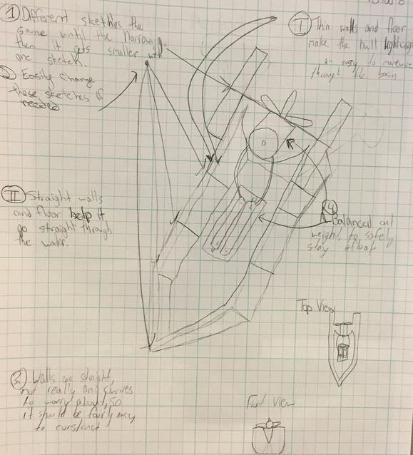
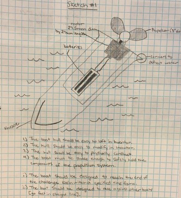
79 Assignments Page 79 Solo Design Wednesday, March 16, :19 PM Research, design, build and test a boat. Design Constraints The boat hull should be easy to loft in Inventor. The hull should be easy to modify in Inventor. The hull should be easy to physically construct. The boat must be stable enough to safely hold the components of the propulsion system. You must guess what dimensions would work best for your hull. Secondary goals i. ii. The boat should be designed to reach the end of the challenge basin within a specified time frame. The boat should be designed to race against other boats [go fast in a straight line].
80 Assignments Page 80 Generate Concepts Tuesday, March 23, :44 AM Brainstorm Solutions: Make small, thumbnail-sized sketches of ideas you have for what would be the best boat shape. Write down important ideas or concerns you have, especially ones that are hard to sketch. Research: Read some of the research pages in this section. Use the internet to look up ideas for your boat. Save pictures of any designs you think are particularly good.
81 Assignments Page 81
82 Research: Definitions Length = tip of the front [bow] to the center of the back [stern] Width [beam] = the widest point of the boat Freeboard = the distance between the deck of the boat and the level of the water Draft = how far the boat s hull will extend underneath the surface of the water Height = Freeboard + Draft = bottom of the hull [the keel] to the top of the hull [deck] Assignments Page 82

83 Research: Hull Design notes Monday, March 17, :06 AM Why a boat Floats Bow Shapes Assignments Page 83


84 The Keel Assignments Page 84


85 Underwater Contours Deadrise Assignments Page 85


86 Sheer Stability Assignments Page 86
87 Assignments Page 87 Research: Power parts Monday, March 17, :18 AM Propulsion system components Air propeller Electric motor 23.5mm dia. x 27mm length 2 AAA batteries Power switch Battery holder optional Motor clamp Optional

88 Assignments Page 88 Conceptual Documents: Friday, March 16, :07 AM Arrange the papers so your favorite annotated sketch is on top. Put your name and period at the top of the first sheet. Hand in, stapled: On Top -2 Annotated sketches of your best boat ideas. I do not need to sign off the sketches. The sketches should show the dimensions of your hull and where the engine parts will go. Remember that annotated sketches should also indicate where major design constraints are addressed. Next - 10 Pictures of boats from your research. Bottom - 10 Thumbnail sketches of your hull ideas. Example Solo Boat Annotated Sketches:
89 Assignments Page 89

![You may use other features [like Extrude] to modify the basic hull you create.](/docs-images/88/117471285/images/90-3.jpg "Design Review Create an A-sheet with a 1:1 scale view of the top and side of your hull.")

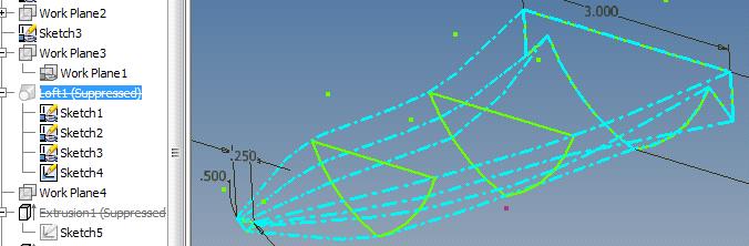
90 Develop a solution Monday, March 17, :11 AM Loft a solid hull model of your design in Inventor. You may use other features [like Extrude] to modify the basic hull you create. Design Review Create an A-sheet with a 1:1 scale view of the top and side of your hull. Place test parts on your A- sheet and ask yourself if the boat would be stable enough to hold everything while the propeller is spinning. Make rib sections Slice "ribs" out of the solid hull, and save them as separate Inventor files. Assignments Page 90

91 Assignments Page 91 Loft a solid hull Friday, March 15, :03 PM To create a solid hull like this: Create a sketch plane, and draw the outline of the back of your hull on the plane:
92 Assignments Page 92 Then make an offset plane in front of your sketch, the same distance as the length of your hull: Make a small sketch to be the front of your boat:

93 Assignments Page 93 Make some sketches in between: Then combine them together, in a single loft:
94 Assignments Page 94
95 Assignments Page 95 Design Review Tuesday, March 19, :36 AM When your hull is done, but before you start slicing ribs from your hull model in Inventor: 1. Make a full size, 1:1 scale multi-view of your hull or pontoon parts on an a-sheet drawing. Side and top view, actually. Then you can see how big your boat will be when you build it: Then Picture the batteries, the motor, and a spinning propeller mounted on your boat. Then, ask yourself: Will my design remain stable? If not, don't bother making ribs: Re-design

96 Assignments Page 96
97 Assignments Page 97 Make rib sections Wednesday, March 21, :04 AM Create a working copy of your hull file with a different name. You don't want to accidentally ruin your hull design. Use Inventor to "cut" ribs out of your hull model. The more ribs, the stronger your boat, but it will take longer to construct. 1. Set up the sketch. Make a sketch plane parallel to the side of your boat. Create big and little two point rectangles: Make sure the large one overhangs the hull on all sides. Dimension the small one to foamcore thickness (3/16" or 0.188"). 2. Create Ribs and stern piece: Center over one of the profile planes. Extrude cut everything else:


98 Assignments Page 98 Click Inventor logo, choose Save as: Rename each rib as a separate Inventor part file. Hit your back button. Drag the small rectangle to a different spot. Repeat as needed. 3. Create the Bow piece Make a sketch plane parallel to the top of your boat. Make Big and little two point rectangles again, but slightly different:

99 Assignments Page 99 Center the red line over the place where you cut out the last rib section. Extrude cut the bow piece.


100 Construct/Test Model Monday, March 17, :12 AM Create a Cut Sheet: Make up an A-sheet showing all your ribs. Make sure all the rib pieces are placed in a 1:1 scale. If you have room, you can place them on the same drawing you used for your design review. Print out the A-sheet. Cut out your ribs: Cut Foamcore Request a piece of foamcore. Place the A-sheet on top of the piece of foamcore. Move it around as you cut ribs out of the foam core, OR Use scissors to cut your pieces out of the A-sheet before putting them on the foamcore. Build your physical test model: Hot Glue Use scrap material to make some "spine" pieces and a place to put the engine components. Glue the ribs together using a piece of scrap foam core as a "deck". Use as much scrap as you want to attach your ribs together. The "spine" pieces do not have to run the entire length. "Skin" the hull: Stick strips of duct tape on to the table [sticky side down], and seal the overlaps as you go. Assignments Page 100
101 Use only enough tape to cover the sides of your boat, leaving the top open. If you don't have quite enough, you can always add some tape on afterwards. Peel the sheet off the table, and flip it over so the sticky side is facing up. Place your rib assembly on the duct tape, with the top facing up. Wrap the duct tape "sheet" around the sides of your boat, making sure to seal all gaps in the tape. Trim off any excess tape with scissors, NOT an x- acto knife. Test for buoyancy and stability. Modify your model to correct the problems you encounter, then re-test. You can physically alter the model you built, or you can re-design your hull in Inventor. Complete a Test Report when you are done testing and modifying your hull. Assignments Page 101
102 Assignments Page 102 Cut Foamcore Wednesday, March 21, :51 AM Setup Collect mat, straight edge, and materials. Take X-Acto knives from rack at front, put back in rack at end of period when finished. All cutting on mats at table. Keep piece flat on mat when cutting. Keep off-hand and body out of way of blade. Clean edges Cut two or three times for each line: once through each layer of foamcore. Use a straight edge to guide the cut. Especially for 2nd or 3rd cut in same place. Watch for knife jumping. If you have to force the blade, its dull and should be changed [never more than once per period]. New blades: Change blades at cart Use "wrench" to remove
103 Assignments Page 103 Hot Glue Monday, March 25, :38 PM Go to the glue station in room 166. You are only there to glue your hull. Anyone not actively gluing shouldn't be there. You are not allowed to interact with students from the other class. All Other work is done in Room 154, including cutting. Plug a gun into an outlet. Always do your gluing over the cardboard. Test if the gun is ready by slightly squeezing the trigger and seeing if a little glue comes out. If the gun is out of glue, get a stick from the table or come see me. Glue guns should be unplugged when you have finished using them, even if the period hasn't ended. Because of this, even an unplugged gun could be hot. Do not waste glue!
104 Assignments Page 104 Test Monday, March 25, :42 PM After enclosing the foamcore ribs of your boat with duct tape, perform the following tests, in order. Your boat must pass one test before you go on to the next. Test #1 Waterproof Procedure Is it leaking? Why or why not? #2 Floatation Does it fall over or lean to one side? #3 Buoyancy Test motor parts piled in the boat, NOT placed. Can it hold the weight of the engine components? Is there freeboard? Remember, boats need to be open. #4 Stability Test motor parts in design positions Tape or pin parts in place roughly where you designed them. Can the prop spin without hitting the boat or the water? Do not leave test motor parts on your test boats! You may modify your hull using scrap foam core and duct tape to get an idea of how to improve your design. Once you have tested for the first time, you can make any modifications you think you need without getting
105 Assignments Page 105 any sign-offs from me. Change your design so that you can make it work. You should design, build and test as many times as you can in the allotted period.
106 Assignments Page 106 Test Report Monday, April 04, :24 AM 1) 2) 3) 4) 5) 6) Label your hull with your name. You can write your name on a piece of masking tape. Then, make a Test Report in Microsoft Word: Make a screen capture of your design from Inventor, or take a picture of your modified hull. Screen Image [Screen Capture] Digital Camera Measure and record your hull's Height, Width [beam], and Length. a. Do not include support structures. Write down at least 3 good features of your model. Write down any improvements you would make to your model and why. If you have passed the Float test [doesn't leak or flip over]: Place the test motor components onto your boat in the places you designed. Measure your boat's Freeboard. Calculate your boat's Draft = Hull Height - Freeboard.
![Digital Camera Tuesday, December 06, 2011 8:42 AM Still cameras [usually better than phone w/ equal MP] Taking pictures: Flip switch to red camera Getting files: Flip switch to black arrow Lightning](/docs-images/88/117471285/images/107-0.jpg "bolt = Flash Try with and without 1) 2) Take multiple shots Brace the camera to reduce vibration Keep the USB cable with the camera Return both to me Don't leave your pictures on the camera!")
107 Digital Camera Tuesday, December 06, :42 AM Still cameras [usually better than phone w/ equal MP] Taking pictures: Flip switch to red camera Getting files: Flip switch to black arrow Lightning bolt = Flash Try with and without 1) 2) Take multiple shots Brace the camera to reduce vibration Keep the USB cable with the camera Return both to me Don't leave your pictures on the camera! Flower = Macro mode for close subjects "Rule of arm" : turn on for any distance thing between wrist and shoulder Assignments Page 107
108 Assignments Page 108 Team Design Friday, March 21, :58 PM Research, design, build, test and race a boat: Design Constraints The boat must be stable enough to safely hold the components of the propulsion system when racing against other boats. The boat must reach the end of the challenge basin within a specified time frame [to be specified later]. Hulls must allow visual and physical access to the inside of the main hull of the boat. The part of the boat that supports the motor parts must be open. Maximum Allowable dimensions Total width = 6.5" [includes hull, pontoons, etc.] Individual part width= 5" Length = 8.0" Draft = 2.5" Ribs and Keel: Maximum thickness of boat shell and keel pieces = 0.10" 0.075" < Cutting Width < 0.15" Cutting Width = the dimension of your "slice" when making ribs Same dimension restrictions apply even if the shelling method is not used to hollow the hull. Only one non-hollow piece will be 3D printed: Usually its the stern rib, but it can be any part. Must be "flat." Flat = no higher than 0.15 inches when laid down 6. Any parts that touch the water must be made in the 3D printer and meet all the above requirements. Excessive amounts of glue or tape will not be permitted. Only materials or parts from LHS will be permitted (e.g., can't use your own batteries.
109 Boat Design Map Blue underline = link to more info Design Constraints Define the problem Design Proposal Annotated sketches/pictures Decision Matrix Concept Documents: Generate Concepts Develop a Solution Make your hull parts in Inventor 1st. Ribs and keel Make Support and maybe Decoration parts in Inventor Make Motor Components in Inventor Motor components Construct/ Test Models Export your hull parts for 3D printing Create 3D Printer parts Put your hull together 1st. Hull Assembly Determine density of motor parts Finding Density Assign similar density material type to motor and batteries Create an A-sheet Virtual Hull Model Drawing Construct a Virtual Boat. Boat Assembly Virtual Boat Assembly In Inventor Request 3D printer parts Wait for 3D printer parts Build your hull and make sure it floats Build the Hull Optimize the position of your motor and batteries Center of Gravity [ CofG ] testing Test Hull model and collect data. Build your boat and make sure it can handle the motor parts Construct a physical boat. Test boat model and collect data Document your final design Virtual Boat Model Drawing Analyze test data Test Boat model and collect data. Construct a physical, powered Boat. Request Stability check from Teacher to receive working motor parts Assignments Page 109
110 Evaluate the Solution Modify boat as needed Maintain documentation Attach support/decoration parts RACE! Assignments Page 110
111 Assignments Page 111 Model Definitions Friday, April 17, :55 PM Virtual model Design object or collection of objects [assembly] created on a computer. Physical model Design object or collection of objects created using actual, physical materials. Hull assembly Assembly of ribs and keel only. No support, decorative, or motor components. Boat assembly Assembly of all boat parts that will be on the final racing boat. Applications Virtual Hull Request 3D printer parts Virtual Hull Boat Center of Gravity test Physical Waterproof, Flotation, and Buoyancy tests Stability test and Time trials
112 Assignments Page 112 Generate Concepts Tuesday, March 23, :44 AM Brainstorm Possible Solutions Design Proposal Based on team members' test reports from the solo design phase, list the things you want your designs to accomplish or the things you want your design to avoid. Be sure to also include the project design constraints. Annotated sketches/pictures Based on what you put in your Design Proposal, come up with ideas for your team boat design. If your solo boat designs match up with your Design Proposal, you may use them as some of your four design ideas. Select an Approach Decision Matrix Based on your Annotated sketches and Design Proposal, use a Decision Matrix to decide which of the four designs best matches the ideas in your Design Proposal.
113 Assignments Page 113
114 Assignments Page 114 Design Proposal Tuesday, March 19, :17 AM Teams must discuss and draft a Design Proposal: Compare notes and information learned by each team member during the solo test phase. Create a team Design Proposal in MS Word. Include the ideas your team agreed on, as well as the design constraints for this phase of the project: Design Constraints
115 Assignments Page 115 Annotated sketches/pictures Tuesday, March 19, :15 AM Annotated sketches/ pictures: Teams must complete at least 4 proposed designs. You may use your solo designs, but you must have at least one brand new design. Must have a picture or sketch of each design. For solo designs, you may: 1. Use the original hand drawn sketch [as long as it matches your new model]. 2. A screen capture of the Inventor model. Screen Image [Screen Capture] 3. A digital photo of the physical model placed in a Word document. Must include dimensions [HWL and estimated freeboard]. Must show the position of motor components and support pieces. Need to be able to easily replace/repair components. Flash Drives for transferring files may be borrowed from Mr. Snider.
116 Assignments Page 116 Decision Matrix Wednesday, April 06, Open the files for: Your good/bad lists from your Test Reports. Your team design proposal. Write down the categories of things you identified. E.g., if you said its fast, the category would be speed. Combine your lists of categories. Your list should include: All the categories you identified. Major design requirements [HxWxL]. Make a table of your hull choices and categories: You may use MS Excel, Google Sheets, or the Decision Matrix template: <file://r:\projectleadtheway\share\snider\ddp Honors \Decision_Matrix_Template.doc> Your solution name should match up with your design sketches. 5. Score the performance of each option. Scores should be from 1 to 3 or 1 to 5, with a higher number indicating better performance. It s a Score, not a ranking: two designs could have the same number. You're evaluating the designs represented by your annotated sketches or annotated pictures.
117 Assignments Page 117 Don't score a design based on whether the solo design was weak: Leaking can be fixed with careful construction If its too shallow [freeboard], add on panels If its too short, keep ribs and just re-do the keel 6. Add up the scores for each individual alternative, and the design with the highest number is the winner In the event of a near-tie: The team shouldn't pick a boat because:
118 Assignments Page 118 Concept Documents: Friday, March 16, :07 AM Hand in, stapled: a) b) c) Your team's Design Proposal. 4 Annotated sketches/pictures of your best boat ideas. Your team's Decision Matrix. Arrange the papers so your Design Proposal is on top. Put your names, Team letter and period at the top of the first sheet.
119 Assignments Page 119 Develop a solution Monday, March 17, :11 AM Create Detailed Design Solution Part files Ribs and keel Hull Assembly Assembly Constraints Motor components Support and Decoration files Technical Drawings Drawing Files Virtual Hull Model Drawing
![Assignments Page 120 Ribs and keel Thursday, April 19, 2012 8:30 AM 1. Start with a solid hull for a pontoon or boat 2. 3. Make it hollow Thickness = shell dimension [0.10"] Leave the top on the boat!](/docs-images/88/117471285/images/120-0.jpg "Hollowing the hulls Note: Once the hull is hollowed out, you can make copies of the hull and have more than one team member working on making ribs. 4. Cut out a keel a.")
120 Assignments Page 120 Ribs and keel Thursday, April 19, :30 AM 1. Start with a solid hull for a pontoon or boat Make it hollow Thickness = shell dimension [0.10"] Leave the top on the boat! Hollowing the hulls Note: Once the hull is hollowed out, you can make copies of the hull and have more than one team member working on making ribs. 4. Cut out a keel a. Make a sketch at the back of the boat Note the dimensioning on the rectangles

121 Assignments Page 121 b. Perform an extrude cut the length of your boat. Be sure to cut the small rectangle at the top of the boat to remove the "top" of the keel c. Save your file as the keel part before hitting the back button in Inventor. 5. Cut out a keel space so the ribs can fit over the keel you just made. 6. Cut out the ribs as you did for your solo model.
122 Assignments Page 122 Use the same process for making ribs that you used on the solo boat. Make rib sections The last rib [at the back of the boat] will be printed as a solid for tape anchoring " < Cutting Width < 0.15" Cutting Width = the dimension of your "slice" when making ribs Use the smaller dimension if you have a lot of ribs. Use the larger one if there's only a few.

123 Assignments Page 123 Hollowing the hulls Thursday, April 10, :21 AM The easiest way to make your hollow is to do a regular shell. However, complex boat shapes may interfere with the standard shell to the inside. Some options you can try: Shell to the outside. Choose the second of the shell buttons.


124 Assignments Page 124 Do 2 lofts: One with a simple shape which is then shelled. The 2nd is the fancy curves along the bottom, which don't have to be Eliminate fancy curves. Sharp points with two sides of a curve close to each other often Do some extrude cuts


125 Assignments Page 125 Place a work plane through the center of the hull. Create a sketch and use slice graphics to draw and extrude Draw lofts with an offset on each face, then just loft the
126 Assignments Page 126 Motor components Tuesday, March 19, :29 PM Reverse Engineer the parts of the propulsion system. 1st. 2nd. You do not have to reverse engineer the propeller or the switch. I will provide the propeller to you. The switch and wires do not have to be modeled in Inventor. Remember Visual, Functional, Structural. Most of the dimensions of the motor parts only have to be approximate. Please only use one part at a time: Sketch it, measure it, then put it back. The sketches are yours for capturing functional dimensions. They do not have to be handed in. Do not model separate parts as one object: E.g., model batteries separate from the case. You may want to move batteries around to balance the boat. Objects of different dimensions act differently even when the weight is the same. You have to be able to show someone how to build your boat using the parts. Propulsion system components Air propeller Electric motor 23.5mm dia. x 27mm length 2 AAA batteries
127 Assignments Page 127 Battery holder optional Power switch Motor clamp Optional
128 Assignments Page 128 Hull Assembly Monday, April 18, :14 PM In an Inventor assembly file, place all of your virtual hull components (ribs and keel). Create an assembly of your hull with all of the components in their designed position relative to each other. Assemblies do NOT have to be fully constrained, but Parts do have to be in their proper position. Note: We will not need any Multi-view [Orthographic + Isometric] drawings for any of your parts. The Virtual Hull Model Drawing is the only one we need.

129 Virtual Hull Model Drawing Tuesday, April 12, :45 AM You must complete and hand in this drawing before your 3D parts are submitted. 1. Title block a. Team letter b. Class period c. Date of submittal 2. Isometric view Shows assembly with ribs, keel, and transom [if needed]. Can be any scale necessary to fit. All ribs should be one color with another color for the keel and transom. Include balloons. Boats with more than one hull [i.e., pontoon boats] should provide an A- sheet for each hull. 3. Parts list Names should match file names of.stl and.ipt files submitted for 3D printing. 4. Side view of assembly showing spacing of ribs. Create at 1:1 scale Assignments Page 129
130 Assignments Page 130 Construct/Test Physical Hull Model Monday, March 17, :12 AM Construct a physical Hull. Create 3D Printer parts Make and name your 3D Printer files Export all your files first to your R:\ drive. Each hull part must have its own.ipt and.stl. No assemblies can be processed. File names should be the same as on your a-sheet. If your submitted parts are wrong, incomplete, or improperly named your team goes to the end of the line for printing. Request 3D printing of parts Once you have finished your 3D printer parts, place your Virtual Hull Model Drawing into the hand-in folder to tell me you're ready for your parts to be printed. Don't request the monkey until you have all parts on your R: drive and the hull drawing is in the Hand-In folder. Save the inventor (.ipt and.stl) files for each of your hull parts in the same directory on the flash drive. Build the Hull Glue ribs and keel together. Tape hull/pontoons. Take your time and make as smooth a hull as you can. Connect pontoons with a scrap piece of foamcore for now. For your boat, you may use better pieces or the provided balsa wood. Test Hull model and collect data. Test: Data:
131 Assignments Page 131 Waterproof Floatation Is it leaking? Why or why not? Does it fall over? Buoyancy Test motor parts piled, NOT placed. Can it hold the weight of the engine Is there freeboard? Remember, boats need to be open and survive collisions with the walls or Analyze test data. Make sure your boat passes all three tests before going further in your design, construction and testing.
132 Assignments Page 132 Construct/Test Virtual Boat Model Monday, March 17, :12 AM Construct a Virtual Boat. Virtual Boat Model 1st. 2nd. Insure that the parts of your virtual model behave like their realworld parts by assigning the proper material to your motor components. Finding Density Open a new assembly file and select Place Component to bring the hull assembly into the new assembly file. Add the motor components and any support or decoration parts you created. Note: You could have one team member working on making and assembling the motor components together [motor/propeller/clamp and batteries/holder) while others are working on making ribs, and someone else is finding density. Test boat model and collect data a. Make sure you have your motor parts in the best position to maximize the stability of your boat. Center of Gravity [ CofG ] Analyze test data: Test Report: Virtual Boat Model Drawing
133 Assignments Page 133 Finding Density Monday, May 10, :46 AM Determining Mass, Volume and Density Any dimensions, values or calculations need only be accurate to one decimal place [xxx.x]. As a minimum, you need to assign a material property for the batteries and the motor. To calculate density, you need the volume and the weight (mass) of the part. Open the documentation file, and save or print a copy to work with <file://r:\projectleadtheway\share\snider\ddp Honors\Finding Density.doc> Volume [cubic inches] Look up the volume of the part in Inventor iproperties. Iproperties / Physical / Update
134 Assignments Page 134 Conversion Factor Research on the internet to find the number of cubic centimeters in one cubic inch (hint: it's greater than one). The factor only needs to be accurate to one decimal place [xxx.x]. Volume [cubic cm.] Mass Density Multiply the Inventor volume by the conversion factor. Weight Request the electronic balance from Mr. Snider. Weigh your part in grams. = weight/volume [grams/cubic centimeter]. Divide the weight you measured on the balance by the volume in cubic centimeters. Assign a material to your motor and battery parts In Inventor iproperties, find a material that nearly matches the density and assign that material to the parts [battery and motor].

135 Assignments Page 135 Tolerance should be within %. For example, if your calculated density is 10 g/cm3, a value of 8 g/cm3 should work ok. Don't forget to assign a material to the rest of your boat parts as well! The battery case, motor clamp and anything from the 3D printer can be assumed to be ABS plastic. You do not need to assign a property to the propeller. For any foamcore parts, find a material with a density less than 1.0 g/cm3. That's the density of water, and we know foamcore is less dense because it floats.
![Assignments Page 136 Center of Gravity [ CofG ] Thursday, April 28, 2011 12:00 PM 1st. 2nd. 3rd.](/docs-images/88/117471285/images/136-0.jpg "Be sure the material of the motor, batteries and all other boat parts is properly assigned [see Assign a material to your motor and battery parts].")
136 Assignments Page 136 Center of Gravity [ CofG ] Thursday, April 28, :00 PM 1st. 2nd. 3rd. Be sure the material of the motor, batteries and all other boat parts is properly assigned [see Assign a material to your motor and battery parts]. Open your Inventor assembly with the hull and motor parts. Suppress any constraints on the motor and batteries. Press the View tab, and select Center of Gravity [at the far left of the tool bar]. a. 4th. 5th. Experiment with placement of your components. In general, the lower the CofG, the better. You may also want your CofG to be in the middle of the boat from the front to the back. Remember that your components have to be accessible, as well. Identify and create any additional support structures you need to hold your components in their positions. Note: All components must be returned to me at the end of the project. You may not glue them in place. Also, they should be easily detachable in case you need to replace a faulty component. 6th. Place structures in your assembly. Note: Your assembly before you test it has to include each rib, keel, etc as a separate Inventor part.
137 Assignments Page 137 Boat Assembly Monday, April 18, :18 PM In an Inventor assembly file, place all of your virtual boat components (virtual hull assembly, motor parts, and support pieces). Create an assembly of your boat with all of the components in their designed position relative to each other. Assemblies do NOT have to be fully constrained, but Parts do have to be in their proper position. Note: We will not need any Multi-view [Orthographic + Isometric] drawings for any of your parts. The Virtual Boat Model Drawing is the only one we need.

138 Virtual Boat Model Drawing Tuesday, April 26, :13 PM You must complete and hand in this drawing before requesting a stability check from the teacher Title block a. Team letter b. Class period c. Date of submittal Isometric view Shows assembly with all ribs, keel, motor, support and decorative parts. Tape, wire and the switch are not required. Can be any scale necessary to fit. All should be colored to match physical appearance. 3D printer parts can be any color Parts list Sub assembly names are permitted. Assignments Page 138
139 Assignments Page 139 Construct/Test Physical Boat Model Wednesday, April 23, :58 AM Construct a physical boat. Cutout Support and Decoration foam core parts Make an A sheet for cutting, like you did for the solo boat model. Cut parts out of foamcore. Gather test motor components. Attach all components to the hull. Test boat model and collect data Stability Place test motor parts in the design positions Tape or pin parts in place roughly where you determined they should be using the Center of Gravity [ CofG ] test. Can the prop spin without hitting the boat or the water? Is the boat stable? Analyze test data Ask me to verify the stability of your hull. If your boat passes my stability check, I will give your team the working motor parts. 1. Have test motor parts on boat. 2. Instructor verifies boat is safe for working motors. 3. Team returns test motor parts to bin. 4. Team motor components awarded.
140 Assignments Page 140 Construct/Test Physical Powered Boat Model Monday, March 17, :12 AM Construct a physical, powered Boat. After passing your stability test, receive your working motor parts from me. Glue/attach all components to the hull. Wire the parts of the motor together: Wiring Test Boat model and collect data. Tests must be performed in order. Each test should be passed before going on to the next test. Before you test: Wire and secure all motor parts Direction / speed Time trial Does your boat go straight enough to make it to the end of the sink? Sink Traverse Must be observed/timed by a non-team member Times must be provided to instructor Note: Test harnesses Available for team's to evaluate their boat handling characteristics before wiring the motor parts together. Is the model Valid? If not, then Define the Problem: Brainstorming


141 Assignments Page 141 Wiring Tuesday, May 17, :38 AM Design Boat circuit Circuit = circle Wires complete the circle between components. If using the battery pack, connect same colored [black to black, color to color] wires with the switch somewhere in the middle. Notes Connection goes into one end of the battery and out the other. Red wire from motor connects to the + terminal on the battery. Warm/hot batteries = short circuit. Disconnect! Don't store with batteries connected. Build Stripping ends of wires Use wire strippers black wire, use: green wire, use: 18 Make "Hooks" on the end of the wire. Use electrical tape to make connections Gluing or heavy tape makes it harder to fix Use long, thin strips of electrical tape to secure wires Stretch as you apply Test wiring as you go. E.g., complete the circuit to test Test Things that can go wrong: Propeller direction Loose Connections Weak battery strength: Request tester Poor battery placement/hookup
142 Assignments Page 142 Bad switch Bad motor
143 Assignments Page 143 Brainstorming Thursday, May 10, :10 PM Note: this process should be applied after you have received your working motor, and actually run it under power in the sink Review the PowerPoint on Brainstorming. Brainstorming Open the brainstorming table on the Share drive: <file://r:\projectleadtheway\share\snider\ddp Honors \Brainstorming table.doc> You may copy then complete an electronic copy of the table, or print it out and hand write your answers: At the top of your paper, write your undesirable symptom (i.e., what is your boat doing that you don't want it to do?) Tipping over (to one side or backward). 2. Turning in one direction. 3. Slow. 4. Anything else you don't like... Write at least five different problems that may be causing that symptom. Write at least three solutions for each of the five problems. Hand in the completed brainstorming sheet before you resume modifying and testing your boat. You may not request more 3D printer parts until the brainstorming table is completed.

144 Assignments Page 144 Evaluate the Solution Monday, March 17, :53 PM
1. Respect yourself, your associates, and your school.
 Classroom rules Tuesday, August 30, 2011 2:16 PM Rules 1. Respect yourself, your associates, and your school. 2. Enter the room, be seated, and check the board before the bell rings. 3. 4. 5. 6. 7. Eyes
1. Respect yourself, your associates, and your school.
 Classroom rules Tuesday, August 30, 2011 2:16 PM Rules 1. Respect yourself, your associates, and your school. 2. Enter the room, be seated, and check the board before the bell rings. 3. 4. 5. 6. 7. Eyes
Introduction to Autodesk Inventor for F1 in Schools (Australian Version)
") Introduction to Autodesk Inventor for F1 in Schools (Australian Version) F1 in Schools race car In this course you will be introduced to Autodesk Inventor, which is the centerpiece of Autodesk s Digital
Introduction to Autodesk Inventor for F1 in Schools (Australian Version) F1 in Schools race car In this course you will be introduced to Autodesk Inventor, which is the centerpiece of Autodesk s Digital
SolidWorks 95 User s Guide
 SolidWorks 95 User s Guide Disclaimer: The following User Guide was extracted from SolidWorks 95 Help files and was not originally distributed in this format. All content 1995, SolidWorks Corporation Contents
Shaft Hanger - SolidWorks
 ME-430 INTRODUCTION TO COMPUTER AIDED DESIGN Shaft Hanger - SolidWorks BY: DR. HERLI SURJANHATA ASSIGNMENT Submit TWO isometric views of the Shaft Hanger with your report, 1. Shaded view of the trimetric
The Revolve Feature and Assembly Modeling
 The Revolve Feature and Assembly Modeling PTC Clock Page 52 PTC Contents Introduction... 54 The Revolve Feature... 55 Creating a revolved feature...57 Creating face details... 58 Using Text... 61 Assembling
PLTW IED MID TERM EXAM REVIEW Part A Multiple Choice
 2014-15 PLTW IED MID TERM EXAM REVIEW Part A Multiple Choice Directions: Select the letter of the response which best completes the item or answers the question. Then record your answer on the answer sheet
1. Respect yourself, your associates, and your school.
 Classroom rules Tuesday, August 30, 2011 2:16 PM Rules 1. Respect yourself, your associates, and your school. 2. Enter the room, be seated, and check the board before the bell rings. 3. 4. 5. 6. 7. Eyes
Assembly Receiver/Hitch/Ball/Pin to use for CAD LAB 5A and 5B:
 MECH 130 CAD LAB 5 SPRING 2017 due Friday, April 21, 2016 at 4:30 PM All of LAB 5 s hardcopies will be working drawing layouts. Do not print out from the part file. We will be using the ME130DRAW drawing
Quick Start for Autodesk Inventor
 Quick Start for Autodesk Inventor Autodesk Inventor Professional is a 3D mechanical design tool with powerful solid modeling capabilities and an intuitive interface. In this lesson, you use a typical workflow
Lesson 6 2D Sketch Panel Tools
 Lesson 6 2D Sketch Panel Tools Inventor s Sketch Tool Bar contains tools for creating the basic geometry to create features and parts. On the surface, the Geometry tools look fairly standard: line, circle,
Engineering & Computer Graphics Workbook Using SOLIDWORKS
 Engineering & Computer Graphics Workbook Using SOLIDWORKS 2017 Ronald E. Barr Thomas J. Krueger Davor Juricic SDC PUBLICATIONS Better Textbooks. Lower Prices. www.sdcpublications.com Powered by TCPDF (www.tcpdf.org)
Alternatively, the solid section can be made with open line sketch and adding thickness by Thicken Sketch.
 Sketcher All feature creation begins with two-dimensional drawing in the sketcher and then adding the third dimension in some way. The sketcher has many menus to help create various types of sketches.
Lesson 10: Loft Features
 10 Goals of This Lesson Your students will be able to create the following part: profiles chisel This lesson plan corresponds to the Loft Features chapter of SolidWorks Getting Started. SolidWorks Student
Inventor Activity 5: Lofted Vase
 Inventor Activity 5: Lofted Vase In this tutorial, you will use a few new commands to create a free form Lofted object. Sometimes you want to create an object that is not made up of square, flat, or perfectly
Engineering & Computer Graphics Workbook Using SolidWorks 2014
 Engineering & Computer Graphics Workbook Using SolidWorks 2014 Ronald E. Barr Thomas J. Krueger Davor Juricic SDC PUBLICATIONS Better Textbooks. Lower Prices. www.sdcpublications.com Powered by TCPDF (www.tcpdf.org)
Introduction to Sheet Metal Features SolidWorks 2009
 SolidWorks 2009 Table of Contents Introduction to Sheet Metal Features Base Flange Method Magazine File.. 3 Envelopment & Development of Surfaces.. 14 Development of Transition Pieces.. 23 Conversion to
Introduction to Autodesk Inventor User Interface Student Manual MODEL WINDOW
 Emmett Wemp EDTECH 503 Introduction to Autodesk Inventor User Interface Fill in the blanks of the different tools available in the user interface of Autodesk Inventor as your instructor discusses them.
1. Open the Feature Modeling demo part file on the EEIC website. Ask student about which constraints needed to Fully Define.
 BLUE boxed notes are intended as aids to the lecturer RED boxed notes are comments that the lecturer could make Control + Click HERE to view enlarged IMAGE and Construction Strategy he following set of
From the above fig. After sketching the path and profile select the sweep command First select the profile from property manager tree And then select
 Chapter 5 In sweep command there is a) Two sketch profiles b) Two path c) One sketch profile and one path The sweep profile is used to create threads springs circular things and difficult geometry. For
TOY TRUCK. Figure 1. Orthographic projections of project.
 TOY TRUCK Prepared by: Harry Hawkins The following project is of a small, wooden toy truck. This exercise will provide you with the procedure for constructing the various parts of the design then assembling
2809 CAD TRAINING: Part 1 Sketching and Making 3D Parts. Contents
 Contents Getting Started... 2 Lesson 1:... 3 Lesson 2:... 13 Lesson 3:... 19 Lesson 4:... 23 Lesson 5:... 25 Final Project:... 28 Getting Started Get Autodesk Inventor Go to http://students.autodesk.com/
Revit Structure 2012 Basics:
 SUPPLEMENTAL FILES ON CD Revit Structure 2012 Basics: Framing and Documentation Elise Moss autodesk authorized publisher SDC PUBLICATIONS www.sdcpublications.com Schroff Development Corporation Structural
SolidWorks Part I - Basic Tools SDC. Includes. Parts, Assemblies and Drawings. Paul Tran CSWE, CSWI
 SolidWorks 2015 Part I - Basic Tools Includes CSWA Preparation Material Parts, Assemblies and Drawings Paul Tran CSWE, CSWI SDC PUBLICATIONS Better Textbooks. Lower Prices. www.sdcpublications.com Powered
Module 2: Radial-Line Sheet-Metal 3D Modeling and 2D Pattern Development: Right Cone (Regular, Frustum, and Truncated)
") Inventor (5) Module 2: 2-1 Module 2: Radial-Line Sheet-Metal 3D Modeling and 2D Pattern Development: Right Cone (Regular, Frustum, and Truncated) In this tutorial, we will learn how to build a 3D model
Inventor (5) Module 2: 2-1 Module 2: Radial-Line Sheet-Metal 3D Modeling and 2D Pattern Development: Right Cone (Regular, Frustum, and Truncated) In this tutorial, we will learn how to build a 3D model
SDC. SolidWorks Tutorial 2001Plus. A Competency Project Based Approach Utilizing 3D Solid Modeling. David C. Planchard & Marie P.
 2001Plus A Competency Project Based Approach Utilizing 3D Solid Modeling David C. Planchard & Marie P. Planchard SDC PUBLICATIONS www.schroff.com www.schroff-europe.com Project 2 Below are the desired
Lesson 4 Holes and Rounds
 Lesson 4 Holes and Rounds 111 Figure 4.1 Breaker OBJECTIVES Sketch arcs in sections Create a straight hole through a part Complete a Sketched hole Understand the Hole Tool Use Info to extract information
Creo Revolve Tutorial
 Creo Revolve Tutorial Setup 1. Open Creo Parametric Note: Refer back to the Creo Extrude Tutorial for references and screen shots of the Creo layout 2. Set Working Directory a. From the Model Tree navigate
AEROPLANE. Create a New Folder in your chosen location called Aeroplane. The four parts that make up the project will be saved here.
 AEROPLANE Prerequisite Knowledge Previous knowledge of the following commands is required to complete this lesson. Sketching (Line, Rectangle, Arc, Add Relations, Dimensioning), Extrude, Assemblies and
Part 8: The Front Cover
 Part 8: The Front Cover 4 Earpiece cuts and housing Lens cut and housing Microphone cut and housing The front cover is similar to the back cover in that it is a shelled protrusion with screw posts extruding
SolidWorks Design & Technology
 SolidWorks Design & Technology Training Course at PHSG Ex 5. Lego man Working with part files 8mm At first glance the Lego man looks complicated but I hope you will see that if you approach a project one
Drawing and Assembling
 Youth Explore Trades Skills Description In this activity the six sides of a die will be drawn and then assembled together. The intent is to understand how constraints are used to lock individual parts
ADA Curriculum for Pre-Engineering Students Correlation Guide
 ADA Curriculum for Pre-Engineering Students Correlation Guide Madsen/Autodesk Inventor 7: Basics Through Advanced Note: The concepts presented in the ADA Curriculum are covered in the text as they pertain
Module 1G: Creating a Circle-Based Cylindrical Sheet-metal Lateral Piece with an Overlaying Lateral Edge Seam And Dove-Tail Seams on the Top Edge
 Inventor (10) Module 1G: 1G- 1 Module 1G: Creating a Circle-Based Cylindrical Sheet-metal Lateral Piece with an Overlaying Lateral Edge Seam And Dove-Tail Seams on the Top Edge In Module 1A, we have explored
Lesson 4 Extrusions OBJECTIVES. Extrusions
 Lesson 4 Extrusions Figure 4.1 Clamp OBJECTIVES Create a feature using an Extruded protrusion Understand Setup and Environment settings Define and set a Material type Create and use Datum features Sketch
Cube in a cube Fusion 360 tutorial
 Cube in a cube Fusion 360 tutorial n Before using these instructions, it is helpful to watch this video screencast of the CAD drawing actually being done in the software. Click to link to the video tutorial.
Feature-Based Modeling and Optional Advanced Modeling. ENGR 1182 SolidWorks 05
 Feature-Based Modeling and Optional Advanced Modeling ENGR 1182 SolidWorks 05 Today s Objectives Feature-Based Modeling (comprised of 2 sections as shown below) 1. Breaking it down into features Creating
ME Week 2 Project 2 Flange Manifold Part
 1 Project 2 - Flange Manifold Part 1.1 Instructions This project focuses on additional sketching methods and sketching commands. Revolve and Work features are also introduced. The part being modeled is
Veerapandian.K Mechanical Engg Vedharanyam A manual to mechanical designers How Solid works Works?
 Compiled by Veerapandian.K Mechanical Engg Vedharanyam-614 810 A manual to mechanical designers How Solid works Works? Solid works Overview Solid works main idea is user to create drawing directly in 3D
Getting Started. Chapter. Objectives
 Chapter 1 Getting Started Autodesk Inventor has a context-sensitive user interface that provides you with the tools relevant to the tasks being performed. A comprehensive online help and tutorial system
SolidWorks Navigation
 SolidWorks Basics SolidWorks Navigation Command Bar Feature Tree Model Window Simple Box Select the Front plane Create a new sketch Create a Center Rectangle from the origin Smart Dimension the length
Modeling Basic Mechanical Components #1 Tie-Wrap Clip
 Modeling Basic Mechanical Components #1 Tie-Wrap Clip This tutorial is about modeling simple and basic mechanical components with 3D Mechanical CAD programs, specifically one called Alibre Xpress, a freely
Toothbrush Holder. A drawing of the sheet metal part will also be created.
 Prerequisite Knowledge Previous knowledge of the following commands is required to complete this lesson; Sketch (Line, Centerline, Circle, Add Relations, Smart Dimension,), Extrude Boss/Base, and Edit
Foreword. If you have any questions about these tutorials, drop your mail to
 Foreword The main objective of these tutorials is to give you a kick start using Solidworks. The approach to write this tutorial is based on what is the most important knowledge you should know and what
Introducing SolidWorks
 Introducing SolidWorks SAAST Robotics 2008 SolidWorks Software Visually-based 3-D Mechanical design software Engineers and Designers use it to: Quickly sketch out ideas Experiment with features, dimensions
Alibre Design Tutorial: Loft, Extrude, & Revolve Cut Loft-Tube-1
 Alibre Design Tutorial: Loft, Extrude, & Revolve Cut Loft-Tube-1 Part Tutorial Exercise 5: Loft-Tube-1 [Complete] In this Exercise, We will set System Parameters first, then part options. Then, in sketch
Laboratory Exercises
 Laboratory Exercises 4 : 1 Lab 1A Inverted T Inverted T. Draw the solid object shown. Place the origin at the intersection of the faces with the holes in them. The front face is marked for you. Make sure
Revit Structure 2013 Basics
 Revit Structure 2013 Basics Framing and Documentation Elise Moss Supplemental Files SDC P U B L I C AT I O N S Schroff Development Corporation Better Textbooks. Lower Prices. www.sdcpublications.com Tutorial
Pro/DESKTOP Tutorial Drafting Bow Compass
 Pro/DESKTOP Tutorial Drafting Bow Compass Michael Flowers 2005 1 Objectives: To develop confidence with the Pro/DESKTOP software. To learn to utilize extrude, project, revolve, round, and chamfer features.
Siemens NX11 tutorials. The angled part
 Siemens NX11 tutorials The angled part Adaptation to NX 11 from notes from a seminar Drive-to-trial organized by IBM and GDTech. This tutorial will help you design the mechanical presented in the figure
Engineering Technology
 Engineering Technology Introduction to Parametric Modelling Engineering Technology 1 See Saw Exercise Part 1 Base Commands used New Part This lesson includes Sketching, Extruded Boss/Base, Hole Wizard,
Beginner s Guide to SolidWorks Alejandro Reyes, MSME Certified SolidWorks Professional and Instructor SDC PUBLICATIONS
 Beginner s Guide to SolidWorks 2008 Alejandro Reyes, MSME Certified SolidWorks Professional and Instructor SDC PUBLICATIONS Schroff Development Corporation www.schroff.com www.schroff-europe.com Part Modeling
Hydro Hull. Chapter 21. Boat. A. Save as "HYDRO". Step 1. Open your HULL MID PLANE file (Chapter 2).
.") Chapter 21 Boat Hydro Hull A. Save as "HYDRO". Step 1. Open your HULL MID PLANE file (Chapter 2). Step 2. Click File Menu > Save As. Step 3. Key-in HYDRO for the filename and press ENTER. B. Delete Loft1,
Chapter 21 Boat Hydro Hull A. Save as "HYDRO". Step 1. Open your HULL MID PLANE file (Chapter 2). Step 2. Click File Menu > Save As. Step 3. Key-in HYDRO for the filename and press ENTER. B. Delete Loft1,
Revit Structure 2014 Basics
 Revit Structure 2014 Basics Framing and Documentation Elise Moss Authorized Author SDC P U B L I C AT I O N S Better Textbooks. Lower Prices. www.sdcpublications.com Powered by TCPDF (www.tcpdf.org) Visit
Name: Date Completed: Basic Inventor Skills I
 Name: Date Completed: Basic Inventor Skills I 1. Sketch, dimension and extrude a basic shape i. Select New tab from toolbar. ii. Select Standard.ipt from dialogue box by double clicking on the icon. iii.
Activity Pegboard Toy
 Activity 1.5.5 Pegboard Toy Purpose When you receive a toy, what is the first thing you wonder about it? Do you wonder how it works? Have you ever wondered who designed it or who may have made decisions
1. Creating geometry based on sketches 2. Using sketch lines as reference 3. Using sketches to drive changes in geometry
 4.1: Modeling 3D Modeling is a key process of getting your ideas from a concept to a read- for- manufacture state, making it core foundation of the product development process. In Fusion 360, there are
Activity 4.5 Pegboard Toy
 Activity 4.5 Pegboard Toy Purpose When you receive a toy, what is the first thing you wonder about it? Do you wonder how it works? Sometimes when you received or bought a toy, did you ever wonder who designed
Sash Clamp. Sash Clamp SW 2015 Design & Communication Graphics Page 1.
 Sash Clamp 1 Introduction: The Sash clamp consists of nine parts. In creating the clamp we will be looking at the improvements made by SolidWorks in linear patterns, adding threads and in assembling the
for Solidworks TRAINING GUIDE LESSON-9-CAD
 for Solidworks TRAINING GUIDE LESSON-9-CAD Mastercam for SolidWorks Training Guide Objectives You will create the geometry for SolidWorks-Lesson-9 using SolidWorks 3D CAD software. You will be working
Autodesk Inventor 2016
 Parametric Modeling with Autodesk Inventor 2016 Randy H. Shih SDC PUBLICATIONS Better Textbooks. Lower Prices. www.sdcpublications.com Powered by TCPDF (www.tcpdf.org) Visit the following websites to learn
NX 7.5. Table of Contents. Lesson 3 More Features
 NX 7.5 Lesson 3 More Features Pre-reqs/Technical Skills Basic computer use Completion of NX 7.5 Lessons 1&2 Expectations Read lesson material Implement steps in software while reading through lesson material
Introduction To Modeling
 Introduction To Modeling Introduction ProEngineer Wildfire2 is a computer aided design (CAD) program that is used to create models on a computer in three-dimensions. Since three dimensions are used the
Chapter 2: Dimensioning Basic Topics Advanced Topics Exercises
 Chapter 2: Dimensioning Basic Topics Advanced Topics Exercises Dimensioning: Basic Topics Summary 2-1) Detailed Drawings 2-2) Learning to Dimension 2-3) Dimension Appearance and Techniques. 2-4) Dimensioning
Autodesk Inventor 2016 Creating Sketches
 Autodesk Inventor 2016 Creating Sketches 2D Sketch Practice 1 1. Launch Autodesk Inventor 2016 2. Create a new Part file (.ipt) 3. Save File As a. Click on the save icon. b. Save you file onto your flash
Introduction to CATIA V5
 Introduction to CATIA V5 Release 17 (A Hands-On Tutorial Approach) Kirstie Plantenberg University of Detroit Mercy SDC PUBLICATIONS Schroff Development Corporation www.schroff.com Better Textbooks. Lower
Creo Parametric 4.0 Basic Design
 Creo Parametric 4.0 Basic Design Contents Table of Contents Introduction...1 Objective of This Textbook...1 Textbook Outline...2 Textbook Conventions...3 Exercise Files...3 System Configuration...4 Notes
Activity 5.5a CAD Model Features Part 1
 Activity 5.5a CAD Model Features Part 1 Introduction In order to use CAD effectively as a design tool, the designer must have the skills necessary to create, edit, and manipulate a 3D model of a part in
Part Design Fundamentals
 Part Design Fundamentals 1 Course Presentation Objectives of the course In this course you will learn basic methods to create and modify solids features and parts Targeted audience New CATIA V5 Users 1
Diane Burton, STEM Outreach.
 123D Design Tutorial: LED decoration Before using these instructions, it is very helpful to watch this video screencast of the CAD drawing actually being done in the software. Click this link for the video
Up to Cruising Speed with Autodesk Inventor (Part 1)
") 11/29/2005-8:00 am - 11:30 am Room:Swan 1 (Swan) Walt Disney World Swan and Dolphin Resort Orlando, Florida Up to Cruising Speed with Autodesk Inventor (Part 1) Neil Munro - C-Cubed Technologies Ltd. and
11/29/2005-8:00 am - 11:30 am Room:Swan 1 (Swan) Walt Disney World Swan and Dolphin Resort Orlando, Florida Up to Cruising Speed with Autodesk Inventor (Part 1) Neil Munro - C-Cubed Technologies Ltd. and
Parametric Modeling with Creo Parametric 2.0
 Parametric Modeling with Creo Parametric 2.0 An Introduction to Creo Parametric 2.0 Randy H. Shih SDC PUBLICATIONS Schroff Development Corporation Better Textbooks. Lower Prices. www.sdcpublications.com
CREO.1 MODELING A BELT WHEEL
 CREO.1 MODELING A BELT WHEEL Figure 1: A belt wheel modeled in this exercise. Learning Targets In this exercise you will learn: Using symmetry when sketching Using pattern to copy features Using RMB when
1. Create a 2D sketch 2. Create geometry in a sketch 3. Use constraints to position geometry 4. Use dimensions to set the size of geometry
 2.1: Sketching Many features that you create in Fusion 360 start with a 2D sketch. In order to create intelligent and predictable designs, a good understanding of how to create sketches and how to apply
Below are the desired outcomes and usage competencies based on the completion of Project 4.
 Engineering Design with SolidWorks Project 4 Below are the desired outcomes and usage competencies based on the completion of Project 4. Project Desired Outcomes: An understanding of the customer s requirements
Table of Contents. Lesson 1 Getting Started
 NX Lesson 1 Getting Started Pre-reqs/Technical Skills Basic computer use Expectations Read lesson material Implement steps in software while reading through lesson material Complete quiz on Blackboard
Working With Drawing Views-I
 Chapter 12 Working With Drawing Views-I Learning Objectives After completing this chapter you will be able to: Generate standard three views. Generate Named Views. Generate Relative Views. Generate Predefined
Activity Pegboard Toy
 Activity 1.5.5 Pegboard Toy Purpose When you receive a toy, what is the first thing you wonder about it? Do you wonder how it works? Have you ever wondered who designed it or who may have made decisions
Module 1H: Creating an Ellipse-Based Cylindrical Sheet-metal Lateral Piece
 Inventor (10) Module 1H: 1H- 1 Module 1H: Creating an Ellipse-Based Cylindrical Sheet-metal Lateral Piece In this Module, we will learn how to create an ellipse-based cylindrical sheetmetal lateral piece
Module 2.1, 2.2 Review. EF101 Analysis & Skills Module 2.3. Sketched Features and Operations. On-line Help Two Locations
 EF101 Analysis & Skills Module 2.3 Engineering Graphics Revolved Features Placed Features Work Features Module 2.1, 2.2 Review What are the three types of operations for adding features to the base feature?
Quick Start - ProDESKTOP
 Quick Start - ProDESKTOP Tim Brotherhood ProDESKTOP page 1 of 27 Written by Tim Brotherhood These materials are 2000 Staffordshire County Council. Conditions of use Copying and use of these materials is
Conquering the Rubicon
 Autodesk Inventor R10 Fundamentals: Conquering the Rubicon Elise Moss SDC PUBLICATIONS Schroff Development Corporation www.schroff.com www.schroff-europe.com Schroff Development Corporation P.O. Box 1334
Module 1E: Parallel-Line Flat Pattern Development of Sheet- Metal Folded Model Wrapping the 3D Space of An Oblique Circular Cylinder
 Inventor (10) Module 1E: 1E- 1 Module 1E: Parallel-Line Flat Pattern Development of Sheet- Metal Folded Model Wrapping the 3D Space of An Oblique Circular Cylinder In this Module, we will explore the topic
Activity 5.2 Making Sketches in CAD
 Activity 5.2 Making Sketches in CAD Introduction It would be great if computer systems were advanced enough to take a mental image of an object, such as the thought of a sports car, and instantly generate
Advanced Modeling Techniques Sweep and Helical Sweep
 Advanced Modeling Techniques Sweep and Helical Sweep Sweep A sweep is a profile that follows a path placed on a datum. It is important when creating a sweep that the designer plans the size of the path
Product Modelling in Solid Works
 Product Modelling in Solid Works In the following exercise you will use solid works to construct the computer mouse shown opposite. In this exercise you will use a number of advanced features to achieve
Tutorial Guide to AutoCAD 2015
 Tutorial Guide to AutoCAD 2015 2D Drawing, 3D Modeling Shawna Lockhart SDC P U B L I C AT I O N S For Microsoft Windows Better Textbooks. Lower Prices. www.sdcpublications.com Powered by TCPDF (www.tcpdf.org)
Made Easy. Jason Pancoast Engineering Manager
 3D Sketching Made Easy Jason Pancoast Engineering Manager Today I have taught you to sketch in 3D. It s as easy as counting ONE, TWO, FIVE...er...THREE! When your sketch only lives in Y and in X, Adding
Vectorworks / MiniCAD Tutorials
 Vectorworks / MiniCAD Tutorials Tutorial 1: Construct a simple model of a little house Tutorial 2: Construct a 4 view Orthographic drawing of the Model These tutorials are available as Adobe Acrobat 4
Create A Mug. Skills Learned. Settings Sketching 3-D Features. Revolve Offset Plane Sweep Fillet Decal* Offset Arc
 Create A Mug Skills Learned Settings Sketching 3-D Features Slice Line Tool Offset Arc Revolve Offset Plane Sweep Fillet Decal* Tutorial: Creating A Custom Mug There are somethings in this world that have
Introduction to SolidWorks Introduction to SolidWorks
 Introduction to SolidWorks Introduction to SolidWorks SolidWorks is a powerful 3D modeling program. The models it produces can be used in a number of ways to simulate the behaviour of a real part or assembly
How to Build a Game Console. David Hunt, PE
 How to Build a Game Console David Hunt, PE davidhunt@outdrs.net Covering: Drafts Fillets Shells Patterns o Linear o Circular Using made-for-the-purpose sketches to define reference geometry Using reference
Creo Parametric 2.0: Introduction to Solid Modeling. Creo Parametric 2.0: Introduction to Solid Modeling
 Creo Parametric 2.0: Introduction to Solid Modeling 1 2 Part 1 Class Files... xiii Chapter 1 Introduction to Creo Parametric... 1-1 1.1 Solid Modeling... 1-4 1.2 Creo Parametric Fundamentals... 1-6 Feature-Based...
Custom Pillow Block Design Protrusion, Cut, Round, Draft (Review) Drawing (Review) Inheritance Feature (New) Creo 2.0
 Drawing (Review) Inheritance Feature (New) Creo 2.0") Custom Pillow Block Design Protrusion, Cut, Round, Draft (Review) Drawing (Review) Inheritance Feature (New) Creo 2.0 Rotatable pdf files: Casting Machining Grease Fitting Boss The general design of the
Custom Pillow Block Design Protrusion, Cut, Round, Draft (Review) Drawing (Review) Inheritance Feature (New) Creo 2.0 Rotatable pdf files: Casting Machining Grease Fitting Boss The general design of the
ENGINEERING GRAPHICS ESSENTIALS. (A Text and Lecture Aid) Second Edition. Kirstie Plantenberg University of Detroit Mercy SDC PUBLICATIONS
 Second Edition. Kirstie Plantenberg University of Detroit Mercy SDC PUBLICATIONS") ENGINEERING GRAPHICS ESSENTIALS (A Text and Lecture Aid) Second Edition Kirstie Plantenberg University of Detroit Mercy SDC PUBLICATIONS Schroff Development Corporation www.schroff.com www.schroff-europe.com
ENGINEERING GRAPHICS ESSENTIALS (A Text and Lecture Aid) Second Edition Kirstie Plantenberg University of Detroit Mercy SDC PUBLICATIONS Schroff Development Corporation www.schroff.com www.schroff-europe.com
Tutorial Guide to AutoCAD 2014
 Tutorial Guide to AutoCAD 2014 2D Drawing, 3D Modeling Shawna Lockhart SDC P U B L I C AT I O N S For Microsoft Windows Better Textbooks. Lower Prices. www.sdcpublications.com Visit the following websites
CATIA Instructor-led Live Online Training Program
 Course Outline Introduction & Understanding to CATIA Environment Introduction & Understanding to CATIA interface Starting new file Understand the Sketcher workbench of CATIA V5 Start a new file in the
ENGINEERING GRAPHICS ESSENTIALS
 ENGINEERING GRAPHICS ESSENTIALS with AutoCAD 2012 Instruction Introduction to AutoCAD Engineering Graphics Principles Hand Sketching Text and Independent Learning CD Independent Learning CD: A Comprehensive