CHARACTERISATION OF SILSESQUIOXANE-POLY(METHYL METHACRYLATE) BLENDS
|
|
|
- Cory Perry
- 6 years ago
- Views:
Transcription
1 CHARACTERISATION OF SILSESQUIOXANE-POLY(METHYL METHACRYLATE) BLENDS BY JESSICA SORRELL A thesis submitted to The University of Birmingham For the degree of MASTER OF RESEARCH Department of Metallurgy and Materials School of Engineering The University of Birmingham January 2010
2 University of Birmingham Research Archive e-theses repository This unpublished thesis/dissertation is copyright of the author and/or third parties. The intellectual property rights of the author or third parties in respect of this work are as defined by The Copyright Designs and Patents Act 1988 or as modified by any successor legislation. Any use made of information contained in this thesis/dissertation must be in accordance with that legislation and must be properly acknowledged. Further distribution or reproduction in any format is prohibited without the permission of the copyright holder.
3 Abstract Silsesquioxanes are a novel hybrid material that have advantageous properties intermediate of polymers and ceramics, due to their inorganic-organic molecular structure. Current research has focused on the potential of this hybrid to enhance conventional materials. Through the incorporation of Silsesquioxanes in their various forms when used as coatings, additives and copolymers dramatic property enhancements have been seen. Recent research has been aimed at investigating whether these enhancements are also seen when Silsesquioxanes are blended with polymeric systems. In research to date property enhancements have been reported, but at present there is limited fundamental understanding of the relationship between the components which are promoting these enhancements. This study aims to investigate the effects on PMMA when solution blended with Vitolane resin containing Silsesquioxanes with high acrylate functionality. Through FTIR, DSC and SEM it was found that the inclusion of this species did have an effect on PMMA. Most noticeably a decrease in Tg was seen in the lower inclusion compositions, 1wt%-10wt% Vitolane, but with little visual evidence of Vitolane s presence within PMMA, highlighting the complex nature of the relationship between the two components. Initially it has been concluded that the Silsesquioxanes within Vitolane cause a plasticization effect in the lower inclusion compositions.
4 Characterisation of Silsesquioxane Poly(methyl methacrylate) Blends Table of Contents Page Chapter 1 - Introduction Literature Review Aims and Objectives 8 Chapter 2 - Experimental Methods Materials Sample Preparation Analytical Methods Scanning Electron Microscopy (SEM) Fourier Transform Infrared Spectroscopy (FTIR) Differential Scanning Calorimetry (DSC) 13 Chapter 3 FTIR Results Neat Components within the Blends PMMA Vitolane Blend Spectra Discussion 23 Chapter 4 DSC Results Neat PMMA Blend Composition First Runs Blend Compositions Further Runs Discussion 31
5 Chapter 5 SEM Results PMMA Blend Compositions Discussion 37 Chapter 6 - Conclusions Conclusions Limitations 41 Chapter 7 Further Work 42 References 44 Appendices 46 Appendix A FTIR 46 Appendix B DSC 53 Appendix C SEM 57


6 Chapter Introduction The demand for hybrid materials and specifically the interest in ceramic-polymer hybrid materials have increased in recent years. Silsesquioxanes, which have inorganic and organic components, have been seen to exhibit favourable properties of the two classes of materials. Therefore having the potential to be exploited in a wide range of applications. Figure 1.1 Silsesquioxanes in Cage and Ladder Formation 1 Silsesquioxanes have been shown to be advantageous especially in Vitolane Resin, the output of a manufacturing method developed by Cambridge based company TWI. The resin which contains Silsesquioxanes in their various forms can be added to coatings, additives and bulk polymers in order to enhance properties such as increased stiffness, improved abrasion and solvent resistance as well as barrier properties. In the case of being incorporated in coatings, in order to improve abrasion resistance, tailoring the molecular structure allows for chemical bonding within the network and for high levels of cross-linking. Vitolane has also been seen in applications requiring improved heat resistance, where ceramic like properties of the molecule increase the softening points of the material they are incorporated into. The nature of the molecule also means that these properties can be tailored by selecting appropriate functionalities (R groups) to enable effective performance in the required application. Vitolane has been designed to be versatile with formulations that are compatible with specific types of materials. For example by tailoring one of these molecules with acrylic 1 Diagram taken from - TWI 1
7 functionality it becomes compatible with acrylate polymers. Silsesquioxanes also have the advantage of having a lower tendency to phase separate and only present the risk of clustering then that of fillers currently in use (Li et al, 2001). This class of material also has manufacturing benefits such as being produced in a liquid form, meaning that they can be introduced in the early stages of formulation. TWI report the success of the technology can be attributed to the use of a silicon with an atomic radius of 0.118nm which is bound into the polymer matrix within the Vitolane. It is also stated that by using this silicon Vitolane has increased enhancement ability when compared to conventional methods which disperse ceramic particles of 9nm or more into the network but have known limitations. TWI have had considerable interest in this product from a number of industries including electrical, packaging and aerospace (TWI, 2007). Poly(methyl methacrylate), PMMA, is one of the most widely used polymers and has been since its commercial introduction in More commonly known by its many trade names such as Plexiglas and Perspex its popularity has been based on its characteristic properties including its very high level of optical clarity, stiffness, brittleness and environmental resistance. With such properties it has been seen in a variety of applications, many of which are as a impact resistant replacement of glass and within the biomedical industry (Ehrenstein, 2001). This study aims to investigate the effects on PMMA when solution blended with a Vitolane resin consisting of Silsesquioxanes with a high acrylate functionality. This will be achieved by employing three analytical techniques, FTIR, DSC and SEM to gain an insight on the possible interactions and relationships between the two on a molecular level. 2
8 1.2 Literature Review Silsesquioxanes consist of a silicon-oxygen framework with attached functionality groups in the forms of pendants, so named due to each silicon atom being bound to 1.5 oxygen atoms (on average) and one R group. The general formula for this type of molecule is (RSiO 1.5 ) n, where R represents the pendant group. Generally R can be a wide range of functionalities, either a hydrogen or organic group including; alcohols, esters, phenyl, aryl, methyl, vinyl, alkyl or any of their derivatives (Ribeiro do Carmo et al,2006; Striolo et al,2005;provatas et al,1997; Baney et al 1995; Li et al, 2001). A large proportion of recent research has focussed on the cage structure, but Silsesquioxanes also exist in random, partial cage and ladder. The cage structure, where n>4 (n corresponds to empirical formula), are more commonly known as Polyhedral Silsesquioxanes, POSS. POSS are tetrahedral structures where the silicon molecules are positioned on the corners with the oxygen molecules interspersed between them as seen below in figure 1.2. Due to the molecules ability to have a wide range of incorporated functionalities it has been found that a high level of compatibility with other materials can be achieved such as with polymers, biological systems and surfaces. This has also led to the ease of modification of the molecule, with the allowed tailoring the material can be suitable for a wide range of applications (Soong et al, 2007; Li et al 2001; Baney et al 1995). Figure 1.2 : Common Forms of POSS Molecules, Random Cage, Cage and Partial Cage. 2 2 Diagram taken from Li et al(2001) 3
9 The organic-inorganic microstructure gives the Silsesquioxanes properties intermediate of ceramics and polymers, hence being classed as a hybrid material. Enhancements in thermal and thermomechanical stability, fire retardant properties, dielectric constant, optical transparency and mechanical toughness are a few of the reported when compared to that of the single materials (Xu et al, 2001; Aldrich, 2001). By combining the two classes of materials in the hybrid nature of Silsesquioxanes it is hoped that the most beneficial properties of the each can be tailored into one material, such as the processability, toughness and cost of polymers with the thermal and oxidative stability of ceramics (Schwab and Lictenhan, 1998). The properties are due to the unique molecular structures which can be formed, depending on production method, with belief that with differing species differing lead properties can be seen ( Li et al,2001). Initially production consisted of complex multistep processes which generally resulted in low yields and required large quantities of silane with long associated reaction times. Studies carried out by Provatas et al (1997) have demonstrated newly developed and improved methods which have brought about the use of complete hydrolytic condensation of their trifunctional monomers si 4 O 6 as reported by Fina et al (2005). Alternatively Xu et al (2001) state that hydrolysis trialkoxysilanes followed by alkali or acid catalyzed condensation can also be used. Li et al (2001) reviewed Silsesquioxanes, along with their synthesis and reported that with the increased research of these molecules there are numerous ways to facilitate tailoring their structures within this method. They also went on to characterise these methods into two main groups of reactions, depending on the starting materials. The first refers to reactions which initially form Si-O-Si bonds and then go on to form the cage structures. The POSS are obtained from monomers of a XSiY 3 nature (where X is a stable substituent such as CH 3, phenyl or vinyl; and Y is a highly reactive substituent such as Cl, OH or OR). This group of reactions also include the formation from linear, cyclic or polycyclic siloxanes which are also derived from these monomers. The second group of reactions refer to manipulation of the substituents associated with the silicon atom without affecting the Si-O-Si backbone. With the long list of favourable properties and the potential enhancements seen when incorporated with other materials Silsesquioxanes have a wide range of applications. Commonly used in sol-gel-polymerisation they have also found widespread use as surface mimics of heterogeneous silica and also liquid crystal polymers. POSS molecules have also 4
10 been known to be utilised as effective nano-fillers. Silsesquioxanes have also been used in numerous industries for applications such as precursors to ceramics, areospace materials, photoresists, semi conductor devices, optical fibre coatings, catalyst carriers as well as protective coatings and dental adhesives (Provatas et al, 1997; Li et al 2001; Xu et al, 2001; Phillips et al 2004). Although research dates back to 1946 when Scott isolated the first silsesquioxane species, (CH 3 SiO 1.5 ) n, an increased interest in researching and developing these molecules has only occurred in recent years. As reported by Baney et al (1995). A majority of this research has been concerned with the incorporation of POSS molecules into other materials, especially polymers. This has involved copolymerisation and also blending. As detailed by Li et al (2001) there have been a wide range of Silsesquioxane species which have been incorporated into polymer systems either by grafting or copolymerisation. Due to fact that no major changes to the processing procedures are needed POSS inclusion via these methods is relatively easy. Li et al also report that the inclusion of POSS cages into polymers in this way have brought about dramatic improvements in the polymer properties, such as increased temperature resistance, reduction in flammability and increase in oxidation resistance among others. Haddad et al (1996) investigated a Styryl-POSS copolymer where it was found the inclusion of POSS influence the solubility and enhanced thermal properties. In particular it was found that the polymer softening temperature could effectively be tailored with varying amounts of POSS inclusion, up to a range of 200 C. It was also found that the decomposition temperature was higher in the copolymers with higher POSS content. Schwab and Lichtenhan (1998) demonstrated that POSS could be easily polymerized in numerous ways including condensation, radical and ring opening polymerisation processes. This study also showed that the inclusion of 10mol% POSS in cyclopentyl-poss-methacrylate/butyl methacrylate caused an increase of 130 C in the Tg when compared to atactic poly(butyl methacrylate). This alteration in Tg was further increased when 20mol% POSS was included. Additionally it was found that only a relatively small amount of POSS was needed to cause enhancements to the original material such as increased resistance to oxidation, reduced flammability, increased miscibility, reduced heat evolution and increased oxygen permeability. 5
11 With the success seen with POSS copolymers research is now concentrated on blending these molecules with polymeric systems to investigate the effect on the parent material and seeing if the advantageous properties already seen in the POSS produce more effective polymeric materials. Initial studies have focussed on miscibility between the polymer and POSS. Kopesky et al (2005) investigated the incorporation of an acrylic species of POSS into PMMA. The key aim of this study was to determine the effect of well dispersed POSS- Nanoparticles on the thermomechanical properties of PMMA. Within the study two variations, modified and unmodified, of the chosen species were also tested to see to what extent this would also affect the outcome. In order to characterise any changes of the polymer DSC, DMA and melt viscosity were employed. Loadings of 0.05 to 0.30 volume fraction in 0.05 increments were produced in both variations of the POSS species and were manufactured through solution blending with THF. It was reported that the inclusion of the POSS species when molecularly dispersed plasticized the PMMA. Loadings between 0.05 and 0.10 resulted in near complete miscibility where a considerable drop in the PMMA s Tg were recorded. Loadings below and beyond this range were seen via DSC and DMA to cause significant phase separation. With such a small range of miscibility the results gained suggest a delicate interaction between to the two components. A subtle difference was also seen between the two variations of the POSS species, with a larger decrease in Tg seen in the unmodified species. This not only shows that the species of POSS could affect the polymer but also processing methods, as described in previous literature, can also have an effect on the extent of alteration to the properties. Several later studies have complimented the work by Kopesky et al (2005), such as Fina et al (2005) and Soong et al (2007) by investigating blending POSS species with other polymers. Within the study carried out by Fina et al (2007) Polypropylene (PP) was blended with an alkyl-poss species. Similar to Kopesky et al two variations within this species were investigated, in this instance the effect of varying chain lengths. There was strong agreement with Kopesky et al s findings that good dispersion and miscibility was only found within a small range of lower loadings. Again it was also found that one variation had a greater effect than the other. POSS species with longer alkyl chain lengths were seen to alter the morphology substantially. It was also found that one species tested increased the crystallisation temperature by up to2-3 C and act as nucleating agent. The POSS species with 6
12 shorter chain lengths was also shown to have an effect and was found to enhance spherulitic morphology. The outcomes of this study also back Kopesky et al s suggestions that the interaction between polymer and POSS are complex when blending and require further investigation to fully understand the nature of this relationship. PVC based blends have also been investigated. Soong et al (2006,2007) carried out several studies discovering that a Methacryl-POSS species caused plasticization effects on PVC. Following the conclusions and outcomes of the initial study further investigation of this effect was undertaken and took in to consideration the extent of possible usefulness by comparing the performance to that of a conventional plasticizer used in industry. The plasticizer in question is that of Dioctylphate (DOP) which although effective at decreasing the brittle nature of PVC has several well known limitations which include volatility, leeching and early onset polymer degradation. It was found that the POSS species did act as a plasticizer without the limitations of DOP but only when fully miscible with PVC. As found in many other publications miscibility was an only found in inclusion, in this case of up to 15 wt%. Due to this small range of miscibility the suitability of POSS as an industrial plasticizer was bought into question and addressed by a new blend composition being produced. The new blend consisted of a combination of POSS and DOP. On completion it was seen that even with minute volumes of DOP the levels of miscibility were greatly increased, from 15wt% to 25wt%. Not only was this the case but it was also reported that the Tg of the POSS-DOP- PVC blend was reduced to such a level that the material became partially rubbery at room temperature and exhibited favourable ductile tensile behaviour. On comparison of the plasticization effects of the two blend compositions it was noted that although the same lower Tg was obtained the mechanical behaviour in low rate compression and tensile tests was significantly different with the POSS-DOP-PVC to that of just DOP-PVC. This suggests that the composition of both POSS and DOP together could have potential in tailoring the mechanical properties of PVC to specific applications. The majority of studies reviewed have agreed that the incorporation of POSS species has indeed brought about alterations in polymer properties, highlighting that these alterations are highly dependent on the species and variation of species of POSS. There is also strong agreement that although there are benefits and huge potential for the resultant blends there are still numerous limitations and issues which need to be overcome. One large limitation is the 7
13 levels of miscibility which can be obtained, where the potential of enhancements are at their greatest, where at the moment miscibility is only reached within a small range of loadings, normally at the lower levels of loading, although the exact optimum levels have yet to be determined. 1.3 Aims and Objectives This study aims to concentrate on the morphological alterations seen with the inclusion of Vitolane resin, incorporating an acrylate-poss with high abrasion resistant properties, on PMMA when the two components have undergone solution blending in varying compositions. This study has incorporated several techniques and processes from the research of Kopesky et al (2005) in order to allow for comparison between the effects of differing POSS species, but also to further investigate the levels of miscibility which can be achieved. This study looks to investigate the lower loadings of the POSS resin in greater detail than that previously researched in the above study, with blends of compositions of 1wt%, 2wt%, 4wt%, 6wt%, 8wt%, 10wt% and also 20wt% and 30wt%. Initially FTIR will be employed to establish the nature of interactions, if any present, between the two components. This method will also be used as a compositional check. By identification of type and location of possible interactions FTIR will form part of an overall analysis to facilitate a greater understanding of the fundamental principles of the enhancements to mechanical properties and alterations seen in previous literature. DSC will also form part of this analysis to aid in the identification of thermal effects of Vitolane on PMMA within the blend. Any variation within the Tg can be a strong indicator of the nature of interaction which may be experienced when the two components are blended. SEM will provide visual analysis into the relationship of Vitolane within the PMMA morphology, with an insight into the states Vitolane takes in the varying composition. The use of all three techniques used in conjunction with each other will enable a more in depth understanding of the morphological effects of the blending of this species of Silsesquioxane on the PMMA polymer system. It is hoped that the results gained will aid in expanding the knowledge on Silsesquioxanes drawn from previous studies. 8
14 Chapter 2 Experimental Methods 21. Materials Vitolane TM POSS samples with high acrylate functionality provided by TWI in an as delivered transparent resin form. PMMA g/mol by Sigma Aldrich in pellet form. For the solution blending procedures Tetrahydrofuran (THF, C 4 H 8 0) 99%, and Hexane Fraction [CH 3 (CH 2 ) 4 CH 3 ], 95% were provided by Sigma Aldrich. It should be noted that when testing commenced the nature of the acrylate functionality provided was limited due to pending patent status of Vitolane technology. For this reason when discussing the nature of Silsesquioxane species being tested the functionality has been based on a general formula for acrylate. 2.2 Sample Preparation In order to establish the most effective production route of the Vitolane-PMMA blends several procedures were conducted. It was important to use a method which was both time efficient and produced a good quality product, but importantly was appropriate with the limited volumes of Vitolane provided whilst allowing comparability with previous research. For this reason solution blending was highlighted as one of the methods which could be used with relatively small amounts of resin and was implemented for all blends. An issue arose from the previous research carried out by Kopesky et al, a lack of production detail, which was overcome by trialling several sub conditions within solution blending in the initial phase of testing. Those that were provided, such as drying and vacuum oven temperatures were followed; I. Vitolane and PMMA collectively dissolved in THF II. Individual components dissolved in THF with a. Bulk mixing and b. Drop mixing There were also two varying methods of retrieving the blend from the solution III. IV. Film Cast Precipitation Eight compositions were produced, by weight percentage, from 1-10wt% in 2wt% increments along with 20wt% and 30wt% Vitolane inclusion to allow for comparability with past literature and to also investigate the effect in the lower ranges to a greater extent (previously reported that miscibility was 9
15 found at 10wt% but only large increments studied). In the initial phase of testing all of the described processes were carried out on a single blend composition (2wt%) with the results determining the production route used for the remaining compositions. I. In appropriate ratios both the Vitolane and PMMA were dissolved in 100ml of THF. To ensure that no or a reduced rate of premature evaporation of the solvent did not occur the container was covered (by foil). The mixture was left to dissolve for a period of 48 hours. The level of dissolution was inspected by eye, complete dissolution was taken when there was no evidence of precipitates or visible solute globules and only a clear and viscous liquid was seen. A further 24 hour period of magnetically controlled mixing at a constant rate was completed to ensure complete dispersion of the two components. II. The Vitolane and PMMA were dissolved as separate components, again in 100ml of THF each. This method was developed to see if a higher level of mixing could be obtained. Each solvent was left for 48 hours where only a transparent liquid could be seen in both cases. The blend was produced by mixing the two components together, still dissolved in the THF. This was done via two methods; a. Bulk mixing consisted of simply adding the two volumes together and magnetically spinning to ensure complete and constant mixing could occur (attempt to restrict the formation of phases within the liquid state). b. A drop mixing procedure consisted of magnetically spinning the PMMA-THF while small amounts of the Vitolane-THF were pipette (2-3ml) at 2 minute intervals. This again was an attempt to obtain thorough mixing. Once all the Vitolane-THF was added the complete mixture remained for a further 15 minutes of magnetic mixing. III. Upon completion of condition I the viscous liquid was decanted into a large foil boat and left in a fume cupboard for 72 hours, allowing for evaporation of the solvent. A relatively thin film was produced and then subjected to a further 48 hours in a vacuum oven at 110 C to remove any remaining solvent which may have been trapped within the blend. Unfortunately on inspection of the end material it was obvious that considerable phase separation had occurred with large areas of transparency and other areas of decreased transparency with a large volume of voids present. This indicated a failure of effective mixing and subsequently this condition was ruled out for further use. IV. In response to the limitations of condition III a precipitation method was trialled. To facilitate precipitation of the liquid solution a non-solvent solute, Hexane fraction, was used. Upon contact with the solution an immediate reaction took place and a large precipitate was produced, in a semi-solid state. After 30 minutes the mass was removed and left to dry in the 10
16 fume cupboard to allow for evaporation of the solvent. As with the previous conditions this material was heated in a vacuum oven. A solid porous mass was produced. All end materials produced in the various methods were then all subjected to heat pressing, at 120 C, creating a thinner flat uniform sample which would allow analytical testing. It should be noted that the times implemented on all of the conditions correspond to those in the study by Kopesky et al. In order for full comparison the neat PMMA that was tested was also subjected to the production process, including being fully dissolved in THF, vacuum oven drying and heat press. 2.3 Analytical Methods Three analytical methods were employed to investigate a variety of aspects concerning the effect of the inclusion of Vitolane on PMMA s molecular structure. To allow for comparison a method previously used by Kopesky et al was incorporated, DSC, along with SEM and FTIR to allow for a more in depth investigation of the morphology to be conducted Scanning Electron Microscopy (SEM) A Joel 6060 SEM was used to image the cross sectional topography of each composition and neat PMMA. This was to investigate if Vitolane, in any form, was visible within the PMMA microstructure and aid in identification of whether miscibility had occurred. Due to the polymeric nature of the blends the sample had to be first sputter coated in gold to allow for the electron charge to be dissipated and prevent any damage to the sample. Concentrated and high strength electron beams are capable of melting the polymer and therefore permanently changing and removing any natural features. Each sample was imaged at a range of magnifications, from x40 up to x1200. Several areas within each sample were also imaged to gain a representative view of the sample as a whole due to inherent variability from the small scale production routes. Due to the already detailed limitation of a polymeric material in SEM x1200 was set as the upper limit due to damage occurring above this. 11

17 Fig 2.3.1: Schematic of Inner Components of a SEM Fourier Transform Infrared Spectroscopy (FTIR) The functional groups within a component will vibrate at a specific region within the infrared (IR) spectrum. This vibration can be identified by passing an IR beam through the component and detecting the amount absorbed, indicating the wavelength and therefore IR band that this functional group corresponds to. Identification of functional groups can then be found in a library of known groups and their bands. The method also allows for calculation of relative volume within the component, in that the higher the absorbency recorded the greater amount is present (Williams &1987). The use of this technique within this study is two-fold; 1. Highlighting possible interactions between the two components changes within the spectra such as a peak shift could indicate the bond groups where alterations might be occurring. 2. As a compositional check it is expected that as the inclusion of Vitolane is increased its associated peaks will become more apparent. Within this block of testing two operating modes were run, 100 scans at a resolution of 4 and 200 scans at a resolution of 4 [(Res4:100) (res4:200)]. In each case a thin section of sample was placed on the diamond and clamped down using the Golden Gate attachment of a Nicolet Magna IR 860 ATR and scanned three times within each condition. The use of the two scanning rates was to ensure a high level of accuracy and reliability. It should be noted that each sample was briefly etched with THF to ensure that the true composition was being tested after the heat press which may have caused contamination of the surfaces which were in contact with the press. 12
18 Fig 2.3.2: Schematic of Inner Components of a FTIR Differential Scanning Calorimetry (DSC) This thermoanalytical technique was used in order to locate the glass transition temperature (Tg) of each blend. From previous literature and the nature of blends if the Tg alters from that of the original material it can be an indication of miscibility. It could also be evidence that the inclusion is causing effects within the original material such as variation of the mechanical properties. Each sample was subjected to three runs of the same heating and cooling regime, within an air atmosphere. This was to ensure that any previous melt history from the production processes was erased, as this commonly gives false results. A Perkin Elmer DSC7 with a TAC 7/DX low temperature chiller was used to programme a heating regime; i. Heating the sample from ambient temperature (25 C) to a maximum of 140 C at a rate of 10 C per minute. ii. The sample was held at this elevated temperature for one minute iii. Cooling rate of 10 C per minute back to ambient temperature was applied. 1 Diagram taken from 13

19 It was hoped that the traces produced would reflect those obtained in previous literature where the inclusion of a POSS species caused a noticeable change in the polymer Tg. Figure 2.3.3: Schematic Diagram of Sample and Reference Pans within Differential Scanning Calorimetry 2 1 Due to the nature of the traces produced in DSC a calculation method must be applied to obtain the Tg. A common method is that of The Richardson Method which shall be used in this study. In the work of Richardson (1975, 1989) a calculation was developed where the curve is effectively standardise to allow for identification of the Tg. In order to standardise the curve several steps must be taken, as seen in figure Trace as produced by DSC software 2. Insert a tangent on the lower portion of the curve 3. Insert a tangent on the upper portion of the curve 4. Insert tangent on the middle section of the curve 5. Insert a line perpendicular to the x-axis within the middle region. This will create two regions enclosed by the inserted tangents. This line must be moved in order to balance the two areas. Once balance a reading of Temperature can be taken. 2 Heat Flow Enod Up (m/w) Heat Flow Enod Up (m/w) Temperature C Heat Flow Enod Up (m/w) Temperature C 2 Diagram taken from : 14
20 3 4 Temperature C Temperature C Heat Flow Enod Up (m/w) Heat Flow Enod Up (m/w) Heat Flow Enod Up (m/w) 5 Temperature C Figure : Processes of Richardson Method to Calculate Tg From DSC Trace 15
21 Chapter 3 FTIR Results and Discussion 3.1. Results Neat Components within the Blends The initial results recorded were those of the two separate components, Vitolane resin and neat PMMA. Each component was scanned three times at two scan speeds; 100 and 200 both at a resolution of 4. Due to the numerous spectra being practically identical only one spectra has been shown to indicate the results gained. These initial spectra have been taken to allow comparison and identification of any changes which may occur as the loading of Vitolane increases in the blends. When comparing the spectra of the two components it should be understood that most groups will be located within the finger print region and may cause incorrect identification, where locations may be similar. The finger print region refers to that of the lower values below ~2000cm -1 and in order to facilitate accurate allocations the overall peak profile in this region needs to be considered as well as the values gained( Williams & Fleming,1987) PMMA Figure : FTIR Spectra of Neat PMMA at Resolution 4, 200 Scans The two peaks with noticeably high absorbencies are that of C=O and C-O, which can be seen in Figure at ~1722 and ~1143 cm -1 respectively, as would be expected when the molecular composition of PMMA is considered. The other peaks which have been identified are that of C-H 16
22 bands in varying locations, relating to vibrational modes. For example the C-H groups seen at ~ cm -1 have a stretching vibrational mode whereas the C-H groups seen at cm -1 are said to have a deformation mode and the weak peak at 752 cm -1 is due to a C-H rocking mode. These peaks are likely to originate from the methyl group bonded to the central Carbon and the methyl group bonded to the Oxygen molecule present, as seen in molecular composition above. It should be noted that although there are many peaks in the lower region (lower than 1500cm -1 ) not all relate to components and can be taken as secondary absorbencies of those already identified. These can also be contributed to the interaction of multiple vibrations within the sample (Williams & Fleming 1987) Vitolane Resin (Polyhedral Silsesquioxane) Figure : FTIR Spectra of Neat Vitolane Resin at Resolution 4 at 200 Scans As with the spectra gained for PMMA there are also key peaks associated with Vitolane. The most obvious peak is that of the Si-O group at cm -1, which is the base component of this molecule as seen in the molecular structure of Silsesquioxanes. Further peaks associated with Si-O can be seen in the cm -1 band. The other peaks which have been identified within the finger print region relate to those associated with the acrylate functionality attached to one of the R groups (as stated by the manufacturer) of the Silsesquioxane; such as a C-O group located at ~1199 cm -1, a C=O group located at ~1706 and a C-H group at ~
23 It can be seen that there is also a broad peak present in the 3500cm cm -1 region. This band relates to a stretching O-H group along with the peak seen at cm -1, relating to a bending O- H group, are both associated with water (Williams & Fleming 1987). There are clearly no O-H groups within the molecular composition of the Vitolane sample, but these two bands are likely to be attributed to absorbed water within the resin. There are several instances when this could have occurred, most likely through the production processes used. The profile of Vitolane is very different to that of PMMA. The peaks are less well defined with numerous side peaks seen. The width of the lower peaks is also greater at the lower absorbencies. It should be noted that the highest absorbency for a peak within this sample is 0.47, which is considerably lower than that of the highest peak in PMMA at An example of how the finger print region can cause confusion can be seen with the presence of peaks in both PMMA and Vitolane which are in the same location but have been allocated different groups. Due to the overall profile and the knowledge of the molecular structure of both it can be seen that they relate to different groups Blend Spectra Generally the peaks locations remained the same as associated with PMMA although as the loadings of Vitolane increased a peak associated with Si-O emerged as would be expected. The main noticeable differences were alterations in absorbencies of the peaks and also the peak profiles. As Vitolane inclusion increased the recorded absorbency decreased and also the peaks became more undefined compared to that of neat PMMA, with a greater width seen in the lower absorbencies, as was seen in the spectra of the neat Vitolane Resin. This can be seen more clearly in Table Peak / Absorbency Blend C-H Si-O C-O CH C=O C-H 1% % % % % Table Summary Table of all Peaks and Associated Absorbencies 18
24 10% % % (Middle) % (Edge) % PMMA Table Summary Table of all Peaks and Associated Absorbencies It is clearly seen that there are considerable changes in some of the absorbencies in several peaks namely those occurring at 1722cm -1 and 1143cm -1 both of which are associated with the C-O and C=O groups of PMMA. Figures and track the alterations in these peaks across all compositions. It is clear to see that the biggest changes occur at loadings greater than 10wt% in both cases, with an onset of return to the original absorbency for PMMA with loadings of 30wt%. It should also be noted that for the 30wt% sample two regions were tested due to noticeable differences in appearance, within a middle region and an edge region, and recorded two very different absorbencies for both peaks. Figure : Overall Change in Absorbency of Peak Occurring at 1722cm -1 Wavenumbers 19
25 Figure : Overall Change in Absorbency of Peak Occurring at 1143cm -1 Wavenumbers Figure : FTIR Spectra of 4% Vitolane-PMMA Blend at Resolution 4, 200 Scans 20
26 Figure : FTIR Spectra of 10% Vitolane-PMMA Blend at Resolution 4, 200 Scans Figure : FTIR Spectra of 20wt% Vitolane-PMMA Blend at Resolution 400, 200 Scans From the range of spectra selected it can be seen that with the inclusion of Vitolane the peak profile alters to that compared to neat PMMA. Initially, in the lower loadings, such as shown by 4% 21
27 Vitolane-PMMA blend where the peaks are very similar to that of neat PMMA, with only very minute changes in absorbencies seen in several peaks. It is not until loadings of 10wt% or more of Vitolane that considerable changes can be seen. As seen in the spectra of 10wt% (Figure ) the peaks relating to C=O and C-O there is an onset of decrease in absorbencies, reductions of 0.10 and 0.16 respectively. This reduction of these peaks is further seen in the 20wt% loading (Figure ) with a total reduction of 0.30 and 0.31, respectively. This can be seen to reflect the low absorbencies seen in the neat Vitolane spectra. When considering the peak profile as a whole it can be seen that the spectra begin to reflect that of Vitolane more than that of PMMA, which was seen in the lower loadings. It is clear to see that a trough at ~1100cm -1 in PMMAs spectra can no longer be seen in spectra of loadings of 10wt% or higher. The Si-O peaks becoming more apparent with the higher loadings as would expect. As seen in Figure , a comparison between neat PMMA, 10wt% and 20wt% Vitolane-PMMA blend illustrates the key differences. Figure : FTIR Spectra of Comparison between Neat PMMA, 10wt% and 20wt% Vitolane-PMMA Blend at Resolution 4, 200 Scans Although the greatest changes in peaks were seen to be in 20wt% loading of Vitolane it can be seen that the profile changes the most with the 10wt% loadings, where peaks not seen in either neat PMMA or 20wt% blend appear, such an example is at 740cm -1. When comparing neat PMMA to 10wt% it is the profile which has experienced the most significantly changes where as when PMMA is compared to 20wt% all peaks have become suppressed but follow a similar profile. 22
28 Along with the differences within the physical appearance of the 30wt% Vitolane-PMMA blend there were also differences within the spectra gained. It was decided that due to the visible difference between the two regions in this sample that spectra should be gained for each. Most noticeable was that two differing spectra were obtained for the same sample. Although both exhibit similar peak profiles the edge region peaks are somewhat lower in absorbency. This can be seen in both Figure and table Peak/Absorbency % Vitolane Edge % Vitolane Middle Table : Comparison Table of Two Regions Within 30wt% Vitolane-PMMA Blend with Neat PMMA. FTIR - Comparison of 30wt% Middle and 30wt% Edge Vitolane - PMMA Blends Absorbance Wavenumbers (cm -1 ) Figure : FTIR Spectra of Comparison of the Two Regions Within 30wt% Vitolane-PMMA Blend at Resolution 4, 200 Scans 3.2 Discussion The most significant changes when compared to neat PMMA are that of 10wt% and 20wt%, with a large divergence of both the level of absorbency and also the peak profile. This would suggest that in some capacity the Vitolane is affecting PMMA. Generally if miscibility within blends was occurring a 23
29 shift in peaks would also be expected to be seen. From the analysis and spectra it can be seen that this is not the case, with the peak locations staying relatively stationary throughout. This shouldn t be taken as absolute, as the shifts tend to be very subtle with the possibility of being as small as 0.5cm -1 to several Wavenumbers. For this reason it should be taken into account the resolution at which the spectra were gained, at resolution of 4, meaning anything smaller than 4 wavenumbers such as a shift would be missed and therefore should not be fully ruled out. The differences seen within the 30wt% blend could be due to phase separation as is largely suggested by the physical appearance of two regions of varying transparency and the fact that different absorbencies at several peaks were recorded. If this is the case it will be confirmed by SEM analysis. One aspect which can be drawn on is that of composition. The fact that the peaks alter to such an extent with the varying loads of Vitolane shows that the blends do differ in their content. Although the lower loadings only alter to a small extent they still diverge from that of neat PMMA. Especially with such a decrease seen in the 10wt% and 20wt% loadings it suggests that there is a considerable amount present when the sample was tested. The fact that the peak profiles, that the width increases at lower absorbencies further backs this statement in that it starts to reflect the profiles seen in the neat Vitolane Resin. As stated before the fact that so many peaks are located in the finger print region means the true extent of the composition, within this study, can only be suggested as stated before some peaks can be due to the interaction of multiple vibrational modes. 24
30 Chapter 4 DSC Results and Discussion 4.1 Results Neat PMMA In order to obtain the baseline in which to gauge the level of change in Tg across all blends the Tg of neat PMMA was taken first. It was key to ensure that the Tg recorded was that of neat PMMA that had been subjected to the same processes as the blends. This was to ensure that an accurate comparison is being made as it is unknown to what extent the processing methods would have on this technique or the Tg. Each sample underwent multiple runs following the same heating and cooling programme. The initial Tg value obtained, calculated via the Richardson Method (1975, 1989), was C, the DSC trace can be seen in Figure With the completion of the further two runs it was seen that there was some variation, as seen in figures There is also a noticeable difference in the trace profile which has been gained, with the latter traces being of a smoother appearance. PMMA is known to have a Tg between C (Ehrenstein,2001) which indicates that the Tg calculated can be taken as reliable. It should be noted that the first run shows two endothermic transitions not seen in the repeat runs. This can be attributed to likely effects of the production route, where the sample would have had voids present remaining even after heat pressing. On heating within the program large amounts of movement would have occurred as the voids collapsed, causing fluctuations resulting in two apparent Tgs. This is more than likely due to the fact that the subsequent runs only showed one Tg. The initial run will have cleared any previous melt history and improved the contact with the DSC pan, allowing for more accurate and reliable results to be gained. 25
31 Figure : DSC Trace of Neat Processed PMMA First Run Figure : DSC Trace of Neat Processed PMMA Second Run Figure : DSC Trace of Neat Processed PMMA Third Run Figure : DSC Trace of Neat Processed PMMA Fourth Run 26
32 4.1.2 Blend Compositions To ensure comparability each blend composition sample was subjected to the same heating and cooling programme to the neat PMMA. The same method of calculation was applied. Table shows a summary of all the Tgs gained along with all the raw data collected on figure Vitolane Loading of Blend 1% 2% 4% 6% 8% 10% 20% 30% Mid 30% Edge Tg Tg Tg Table 4.1.2: Summary of all Tg Obtained for All Blend Compositions Figure : Graph to Show all Raw Tg Data for all Blend Compositions and Runs 27
33 First Runs 28
34 Figure : All Tg traces for First Run of All Blend Compositions As with neat PMMA there is a noticeable difference between a majority of the first runs with that of the subsequent runs. With the possibility of inaccurate or skewed data due to the variability seen a separate profile is being considered, figure This enables a comparison to a profile gained from the average values calculated from the subsequent runs. This will aid in whether the first run data should be excluded when taking an average to gain an overall change in Tg profile. From this figure an impression of no emerging patterns are given, with both decreases and increases in temperatures seen in adjacent compositions. There appears to be a large initial drop from neat PMMA with inclusion of 1% Vitolane of 10.5 C which is not sustained with greater loadings. At 4wt% there is a single increase back up to C but drops once more with loadings of 6wt% and 8wt% only to increase marginally with 10wt% Vitolane inclusion. If a line of best fit were to be applied (seen on as a dashed line) these values would suggest a steep curve would reflect the behaviour, which on analysis of the other runs seems unlikely. It is also difficult to apply the line of best fit due to the lack of values in the higher loadings. It is also clear to see from figure that the first run values are considerably different to that of the values of run two and three which appear to be in strong agreement with each other. 29
35 Figure : Identification of Possible Trends from First Run Tg s for all Blend Compositions Blend Compositions Further Runs From table and figure it can be seen that unlike the first run values both the second and the third run values seem to be in strong agreement with each other on the calculated Tg value. Due to this agreement an average can be taken confidently to allow for a change in Tg profile to be produced, figure (All composition Tg traces can be seen in Appendix 2) It can be seen that with the inclusion of small amounts of Vitolane there is an effect on the Tg of PMMA, this is seen to a maximum decrease at 10wt% inclusion with a reduction of almost 9 C. When the loading of Vitolane gets more substantial, such as 20wt% or more it can be seen that this initial decrease is no longer seen but the Tg starts to increase back to that of neat PMMA. The trend also suggests that with even higher loadings, above 30wt% that the Tg would be set to return to that recorded of neat PMMA. Although this is the case there are several compositions below 10wt% which show less of a decrease than the others, only giving a suggestion of a change profile, illustrated by the line of best fit in the following diagram. Within the data collected it is noticeable the value obtained for 2wt% does not seem to follow the pattern of the other lower loadings. 30
36 Figure : Change in Tg Profile with Identification of Possible Regions Conversely within this profile there are two apparent regions emerging once a line of best fit has been applied, one region positioned within the lower loadings of Vitolane, 10wt%, and one at the higher loadings of Vitolane, 20wt%. 4.2 Discussion From both the neat PMMA and blend compositions it is clear that the first run results are not a true representation of the Tgs. This can be clearly seen in the graph of all raw data, where the second and third run values are very similar, whereas the first run results diverge from these values considerably. The fact that values couldn t be gained for the higher loadings also strongly suggest that this set of data should be excluded when considering the overall effect of Vitolane s inclusion in PMMA. It is highly likely that the variability seen within the first run is due to the blends ability to retain a melt history. There are a substantial number of heat treatments and processes which are likely to affect the data obtained in the first run. By subjecting the samples to further runs this melt history is cleared through the controlled heating and cooling programme within the first run. This means that the results gained in these further runs are more than likely the true Tg values without risk of skewing from previous processing. 31
37 For this above reason any conclusions which are drawn from DSC will be from the second and third runs, and the change in Tg profile produced from them. As highlighted on the graph it can be seen that there is an emergence of two regions, a clear difference between the lower loadings to that of the higher loadings. This suggests that there are interactions between the Vitolane and PMMA in some capacity. It is thought that there are two possible explanations for the appearance of these regions. A. Miscibility At the lower loading region of Vitolane PMMAs Tg is reduced which can be indicative of miscibility within a blend. This could suggest partial to complete miscibility. The fact that there are two regions present shows that miscibility could only be occurring within small intervals of Vitolane inclusion. This would mean that Vitolane is more likely to be affecting the molecular structure of PMMA at lower loadings. At the higher loadings, with the Tg returning back towards that of neat PMMA could be an indication of phase separation. If this is the case it would be expected that at the lower loadings no clear presence of Vitolane should be seen. At higher loadings visible evidence of Vitolane s presence should be seen in the SEM images collected, illustrating phase separation which occurs with immiscibility within blends B. Plasticization Just as likely is the possibility that Vitolane acts as a plasticizer when incorporated into PMMA. The profile suggests that at the lower loadings the Vitolane is plasticizing the PMMA, which would account for the reduction in Tg. This could be due to the nature of the functionality of the Silsesquioxanes with Vitolane, which would allow for easy attachment to the PMMA chains. Once attached the POSS molecules could be increasing the free space between the PMMA chains, which would reduce the stiffness and plasticize the PMMA bringing about a reduction in Tg (Callister,2007). It could then also be suggested that the reason the Tg increases back to the original value is that in higher volumes the Silsesquioxanes cluster or become rejected by the PMMA. In both cases due to the nature of DSC it will only be with consideration of the other two analytical techniques that the cause of the reduction of Tg within the lower loadings will be clarified. 32

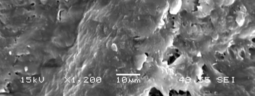
, can be seen.")
 (1) and crazing (2) both of which are indicative of a shear failure.")

38 Chapter 5 SEM Results and Discussion 5.1 Results PMMA To gain a representative view of PMMA multiple images were taken at varying magnifications and locations within the sample. This was to ensure that all features were recorded and to see if any variability occurred. By considering the features present in the neat PMMA it will allow for the identification of any new features due to the inclusion of Vitolane. From figure SEM images showing characteristic features of PMMA, as shown by the work of Rittel (1998), can be seen. The fracture patterns present allow for identification of several key features. The direction of the fracture can be seen in image a) as indicated by the arrow. Several other characteristic features are that of the presence of a shear band b) (1) and crazing (2) both of which are indicative of a shear failure. The uniform topography of the sample is to be expected of an amorphous polymer. a) b) 2 1 Figure : SEM of Neat Processed PMMA at Magnifications x40 and x60 Due to the nature of the Vitolane resin no base images were gained Blend Compositions As with neat PMMA multiple images were taken of each sample in varying locations and magnifications. Due to apparent similarity only a selection of the blend images have been presented in figure , the remainder of images can be seen in Appendix 3. 33


39 Figure : SEM of 1wt% Vitolane Inclusion at Magnifications of x40 and x600 Figure : SEM of 4wt% Vitolane Inclusion at Magnification of x40 and x600 Figure : SEM of 6wt% Vitolane Inclusion at Magnification of x40 and x600 34


40 Figure : SEM of 10wt% Vitolane Inclusion at Magnification of x40 and x600 When comparing the blend compositions to that of neat PMMA SEM shows that the topography is very similar, with the fracture patterns and features inherent to PMMA also being present. Both shear bands and crazing can be clearly seen. It is only at 10wt% inclusion that there seems to be a subtle variation in that the fractures become more pronounced. Variation can also be seen in the 30wt% Vitolane blend as seen in figure Within the top layers of this sample it can be seen that there is a region of very different topography to that of the rest of the sample. For this reason further investigation at a higher magnification was used in an attempt to identify this region. Within this region there is no evidence of crazing, shear bands or any recognisable fracture patterns. The texture is no longer relatively smooth as has been previously seen, instead there appears to be bubbling under the surface. This could be evidence of clusters or aggregates of Vitolane as highlighted in the figure

 Zoom in")


41 a) b) Figure : SEM of 30wt% Blend sample at a) x40 and b) Zoom in of Region of Interest at x600 Indicating Possible Aggregates of Vitolane 36


42 The use of SEM has also highlighted the importance of heat pressing each of the samples after solution blending, precipitation and drying procedures. Figure demonstrates the typical view that would be gained if this step was omitted. It is clear to see that the topography and profile of this sample differs greatly from that of the heat pressed samples. Within the one region captured at this magnification there are several different textures which would have been caused by different cooling rates within the sample. By heating pressing the sample the true topography can be seen unlike this random selection of regions. Figure : SEM of Blend Sample Not Heat Pressed at Magnification x Discussion From the images gained there is a high level of similarity between the blends. A subtle difference was seen in the 10wt% blend where the fracture patterns were more pronounced but generally all the samples were uniform and possessed characteristics inherent to PMMA. The only variation is that of the 30wt% blend, were a small region within the top layer was seen. Overall the SEM is largely inconclusive, with only a hint of a suggestion towards the morphological effect of Vitolane s inclusion. The 30wt% sample hints at evidence of 37
43 Vitolane s presence within PMMA, which is not seen in any of the other blends. It would have been expected that at some point the Vitolane would have become obvious, but this is not the case. When matched with the results from DSC, where there was clear identification of two regions, that at lower loadings the Vitolane and PMMA may have been miscible and immiscible at the higher loadings. With no visibility of Vitolane this no longer seems like a possibility. Immiscibility would be clearly identified by phase separation. Differing phases are not seen in any of the images collected. Although this seems highly likely there is also no evidence of the Vitolane being rejected from the PMMA. This could aid in supporting the suggestion that the Vitolane acts as a plasticizer. At the lower loadings the Silsesquioxanes within the Vitolane could be interacting with the PMMA chains and therefore would not be seen. The appearance of what seem to be aggregates of Vitolane within the 30wt% blend could be evidence of some the Silsesquioxanes being rejected and clustering. The results gained from SEM and DSC implies that the latter is more likely. This would require further investigation, such as more in depth fractography studies which could indicate levels of plasticization. 38
44 Chapter Conclusions Through the use of FTIR, DSC and SEM it has been established that the inclusion of Vitolane resin, a Polyhedral Silsesquioxane compound with high acrylate functionality, has an effect on PMMA. The most considerable differences seen in DSC, with some supporting data from both FTIR and SEM. The use of FTIR has ascertained that the blend compositions are more than likely correct. This can be concluded from the changes in peak profiles tracked through increasing inclusions of Vitolane. The key differences recorded are that of reductions in peak absorbencies as the volume of Vitolane incorporated into the PMMA is increased. It also follows that as the volume of Vitolane is increase the overall profile of the spectra within the finger-print region tends towards that of the neat Vitolane spectra. It also corresponds that in the lower loadings of Vitolane the profile reflects that of neat PMMA. Curiously it was noticed that within the 30wt% loading the two visible regions gained differing spectra. Initially it was thought that this was caused by phase separation but in light of the results gained from SEM this may not be the case. To conclude the reason for this further investigation would be required. Although no peak shifts were detected this should not be taken as absolute due to the limitation regarding the resolution used. Again in order to identify if any peak shifts are present further more in depth testing would be required. The most conclusive results gained within this study are those from DSC. There is a clear indication that the Tg of PMMA is altered with the inclusion of Vitolane. The extent of this alteration seems dependent on the loading of Vitolane within the blend. An important conclusion drawn is that due to a large variation in the first run these values should be excluded. The first runs are indicative of being compromised by the effect of previous melt history. This history is effectively erased after the first run and is considered to not affect the subsequent runs. It was seen from the data deemed viable that two apparent regions were present within the overall change in Tg profile. The lower loadings up to 10wt% caused a reduction in the Tg, the maximum reduction of 9 C reached at 10wt%. Conversely when loadings of Vitolane were over 10wt% this reduction was reversed with the Tg returning that of the original value of neat PMMA. The appearance of these two regions was initially believed to suggest either levels of miscibility or a plasticization effect. After the images 39
45 obtained through SEM it seems more likely that the latter is the cause of the alteration of the Tg. At lower loadings the POSS are thought to interrupt inter-chain interactions reducing PMMAs characteristic stiffness and brittleness and therefore lowering the Tg. This conclusion is in agreement with the findings of Kopseky et al (2005) and other previous literature in which several species of POSS have been seen to act as plasticizers on various polymer systems as discussed in the literature review. It can also be concluded that at higher loadings of Vitolane this plasticization effect is diminished which suggests that a clustering or aggregate mechanism is triggered and rejection of POSS is possible. This again has been found in previous work, where the effect is only seen for a small range of loadings, generally this has been at the lower volume of inclusion. In order to confirm this suggestion further work would be required to investigate chain interactions. With the possible plasticization effect on PMMA it would be worthwhile investigating whether this behaviour is seen in other polymer systems. The results gained from SEM are singularly inconclusive, with a majority of blends displaying the same uniformity and fracture patterns. When matched with that of DSC they give a hint of a suggestion that it is more likely that plasticization is the underlying effect of Vitolane on a PMMA system. There is no evidence of an obvious presence of Vitolane in the higher loadings as would be expected if immiscibility had been reached. Instead at 30wt% there seems to be a very subtle indication of possible aggregates of Vitolane. Due to the tiny amount of these seen it could be taken to support the plasticization conclusion. Through the use of a fractography study it could be seen whether plasticization is evident within the fracture patterns showing increased ductility in the lower loadings. This was not considered within the scope of this study but once again would be a worthwhile area for further research. Overall it can be concluded that Vitolane does have an effect on PMMA which is dependent on the volume of Vitolane included and is in strong agreement with that of previous research. It is more than likely that this is a plasticization effect but due to the already highlighted limitations this study should be seen as a basis for further research into the fundamental principles, behaviour and interactions between PMMA and this particular POSS species. 40
46 6.2 Limitations Within the study there were several limitations which need to be considered and may also have attributed to some of the results gained. Many of these limitations have highlighted areas of further research. A. Only a limited amount of Vitolane resin could be supplied by TWI at a time. In order to ensure that all the blends were comparable the batch from which they were made needed to be the same throughout. This limited the manufacturing options but also ensured that the work carried out was novel. The limited amount of material also meant that the number of blends was limited, for this reason only increments of 2wt% were considered. B. The resolution used in the FTIR testing was at such a level that very subtle peak shifts, 4 wavenumbers, would not be seen. The identification of shift would indicate interactions between PMMA and Vitolane and would therefore aid in the conclusions drawn. The main reason for the use of the resolution was that of available equipment. Although this is a limitation the resolution that was used is sufficient in analysing the blend composition. C. A considerable time constraint was imposed throughout the study mainly due to unforeseen problems faced in initial testing. For this reason only three analytical techniques were employed where it had been hoped that mechanical testing could also be conducted to gain a deeper understanding of Vitolane s effect on PMMA. For this reason the scope of the study was somewhat limited, even with this taken into account it was considered worthwhile undertaking the analytical approach as a large number of previous studies have reported on the mechanical behaviour but lack the understanding of the underlying principles. Although the scope was limited it was felt that it adequately addressed a gap in current research. 41
47 Chapter 7 Future Work Not only would completing these further studies improve the overall understanding of the nature of the possible relationship and interactions which have been suggested but would also aid in the understanding of the limitations and possible errors which occurred in this investigation. I. Manufacturing Processes A more in depth look at the exact effect of the varying processes, such as melt blending, melt mixing as well solution blending in one study. The different procedures will have different heating and cooling regimes which could affect the end product. This could be done by producing several compositions through the varying methods and running a series of tests to see if there is any variation. These would include both analytical and mechanical testing. II. III. IV. Greater Range of Compositions This study aimed to investigate further the lower ranges where miscibility is a possibility. Although a region of possible miscibility has been indicated it would be advantageous to further investigate this lower region in greater detail, reducing the increments to 1wt% or 0.05wt% to enable exact location of complete miscibility if it does in fact occur. It would also be beneficial to study the effects at much higher loadings such as 40wt% to investigate the levels of phase separation or rejection. Mechanical Testing Due to unforeseen circumstances only analytical techniques were employed and although an effect of Vitolane on PMMA was seen it is not a complete view of the full extent of alterations. It would be beneficial to examine the mechanical properties of the blends to see if differing levels of Vitolane inclusion cause variations in performance, and also to see if this POSS species does indeed act as a plasticizer as found on numerous occasions in previous research. Incorporation in Other Polymer Systems To further investigate the possible usefulness of the inclusion of Vitolane Resin. By incorporating into a number of other polymers it could be seen if Vitolane has greater or lesser effect on different polymers. For comparability it could be suggested to test PP and PVC, which have been previously investigated with POSS species. V. Fractography Studies To quantify the level of plasticization from varying blend compositions from the fracture mechanics seen. 42
48 VI. Further FTIR The resolution used was highlighted as a limitation. In order to indentify if there are any interactions occurring and their location within the component groups a smaller resolution should be used to pick up any shift peaks which may have gone un-noticed. 43
49 References Journals Richardson M.J and Savil N.G, (1975), Derivation of accurate glass transition temperatures by differential scanning calorimetry, Polymer, 16, 10, pp Richardson M.J and Aras L, (1989), The glass transition behaviour and thermodynamic properties of amorphous polystyrene, Polymer, 30, pp Soong S.Y, Cohen R.E, Boyce M.C and Mulliken A.D, (2006), Rate dependent deformation behaviour of polyhedral silsesquioxane filled and plasticized PVC, Macromolecules, 39, pp Soong S.Y, Cohen R.E and Boyce M.C, (2007), Polyhedral oligomeric silsesquioxanes as a novel plasticizer for poly(vinyl chloride), Polymer, 48, pp Phillips S.H, Haddad T.S and Tomczak S.J, (2004) Developments in nanoscience: polyhedral oligomeric silsesquioxane (POSS)-polymers, Current Opinion in Solid State and Material Science, 8, pp Provatas A, Luft M, Mu J.C, White A.H, Matisons J.G and Skelton B.W, (1998), Silsesquioxanes: Part I: A key intermediate in the building of molecular composite materials, Journal of Organometallic Chemistry, 565, pp Fina A, Tabuani D, Frache A and Camino G, (2005), Polypropylene-polyhedral silsesquioxanes (POSS) nanocomposites, Polymer, 46, pp Kopesky E.T, Haddad T.S, McKinley G.H and Cohen R.E, (2005), Miscibility and viscoelastic properties of acrylic polyhedral oligomeric silsesquioxane=poly(methyl methacrylate) blends, Polymer, 46, pp Scott D.W, (1946), Thermal rearrangement of branched-chain methylpolysiloxanes, Journal of American Chemistry Society, 68, pp Li G, Wanh L, Ni H and Pittman Jr C.U, (2001), Polyhedral oligomeric silsesquioxane (POSS) polymers and copolymers: A review, Journal of Inorganic and Organometallic Polymers, 11, 3, pp Xu H, Xie P and Zhang R, (2001), Synthesis of characterization of oligomeric silsesquioxane with pendent carboxylic acid groups, European Polymer Journal, 37, pp Schwab J.J and Lichtenhan J.D, (1998), Polyhedral oligomeric silsesquioxane (POSS)- based polymers, Applied Organometallic Chemistry, 12, pp
50 Haddad T.S and Lichtenhan J.D, (1996), Hybrid organic-inorganic thermoplastics: Styryl-based polyhedral oligomeric silsesquioxane polymers, Macromolecules, 29, pp Baney R.H, Itoh M, Sakakibara A and Suzuki T, (1995), Silsesquioxanes, Chemical Review, 95, pp Ribeiro Do Carmo D, Filho N.L.D and Stradiotto N.R, (2007), Encapsulation of titanium (IV) into the NH 4 USY zeolite: Preparation, characterization and application, Materials Research Bulletin, 42, pp Haddad T.S and Lichtenhan J.D, (1996), Hybrid organic-inorganic thermoplastics: styrylbased polyhedral oligomeric silsesquioxane polymers, Macromolecules, 29, pp Books Billmeyer Jr F.W, (1984), Textbook of Polymer Science, 3 rd Edition, Camada, John Wiley & Sons. Callister Jr W.D, (2007), Materials Science and Engineering An Introduction, 7 th Edition, USA, Wiley & Sons. Ehrenstein G.W, (2000), Polymeric Materials: Structure-Properties-Applications, Munich, Hanser. Williams D.H, and Fleming I, (1987), Spectroscopic Methods in Organic Chemistry, 4 th Edition, London, McGraw-Hill Book Company. Websites TWI, (2007), Vitolane Technology [online], [Accessed 2007]. Sigma Aldrich, (2001), Silsesquioxanes; chemfiles [online], [Accessed 2006]. 45
51 Appendix A FTIR of All Samples A.1 Vitolane Resin FTIR Vitolane Resin Sample 1 Wavenumber (cm -1 ) Figure A.1.1 FTIR Spectra of Vitolane Resin Sample 1 at Resolution 4, 200 Scans FTIR Vitolane Resin Sample 1 Wavenumber (cm -1 ) Figure A.1.2 FTIR Spectra of Vitolane Resin Sample 2 at Resolution 4, 200 scans 46
52 A.2 Blend Compositions FTIR - 1wt% Vitolane PMMA Blend Wavenumber (cm -1 ) Figure A.2.1 : FTIR Spectra of 1wt% Vitolane PMMA Blend at Resolution 4, 200 Scans FTIR - 2wt% Vitolane PMMA Blend Wavenumber (cm -1 ) Figure A.2.2 : FTIR Spectra of 2wt% Vitolane PMMA Blend at Resolution 4, 200 Scans 47
53 FTIR - 4wt% Vitolane PMMA Blend Wavenumber (cm -1 ) Figure A.2.3: FTIR Spectra of 4wt% Vitolane PMMA Blend at Resolution 4, 200 Scans FTIR - 6wt% Vitolane PMMA Blend Wavenumber (cm -1 ) Figure A.2.4: FTIR Spectra of 6wt% Vitolane PMMA Blend at Resolution 4, 200 Scans 48
54 FTIR - 8wt% Vitolane PMMA Blend Wavenumber (cm -1 ) Figure A.2.5: FTIR Spectra of 8wt% Vitolane PMMA Blend at Resolution 4, 200 Scans FTIR - 10wt% Vitolane PMMA Blend Wavenumber (cm -1 ) Figure A.2.6: FTIR Spectra of 10wt% Vitolane PMMA Blend at Resolution 4, 200 Scans 49
55 FTIR - 20wt% Vitolane PMMA Blend Wavenumber (cm -1 ) Figure A.2.7: FTIR Spectra of 20wt% Vitolane PMMA Blend at Resolution 4, 200 Scans FTIR - 30wt% Vitolane PMMA Blend - Middle Wavenumber (cm -1 ) Figure A.2.8: FTIR Spectra of 30wt% Vitolane PMMA Blend at the Middle of the Sample at Resolution 4, 200 Scans 50
56 FTIR - 30wt% Vitolane PMMA Blend - Edge Wavenumber (cm -1 ) Figure A.2.9: FTIR Spectra of 30wt% Vitolane PMMA Blend at the Edge of the Sample at Resolution 4, 200 scans A.3 PMMA FTIR - 100% PMMA Sample 1 Wavenumber (cm -1 ) Figure A.3.1: FTIR Spectra of 100% PMMA at Resolution 4, 200 Scans 51
57 FTIR - 100% PMMA Sample 2 Wavenumber (cm -1 ) Figure A.3.2: FTIR Spectra of 100% PMMA at Resolution 4, 200 Scans FTIR - 100% PMMA Sample 2 Wavenumber (cm -1 ) Figure A.3.3: FTIR Spectra of 100% PMMA at Resolution 4, 200 Scans 52
58 Appendix B DSC All Samples B1- Second Run 53
59 Figure B1. 1: All Tg Traces for Second Run for All Blend Compositions 54
60 B2 Third Runs 55
61 Figure B2.2: All Tg Traces for Third Run for All Blend Compositions 56


62 Appendix C SEM of All Samples Figure C3.1: 100% PMMA at Magnifications of x250 and x1200 Figure C3.2: 1% Vitolane - PMMA Blend at Magnifications of x250 and x1200 Figure C3.3: 4% Vitolane PMMA Blend at Magnifications of x250 and x


63 Figure C3.4: 6% Vitolane PMMA Blend at Magnifications of x250 and x1200 Figure C3.5: 8% Vitolane PMMA Blend at Magnifications of x250 and x1200 Figure C3.6: 10% Vitolane PMMA Blend at Magnifications of x250 and x


64 Figure C3.7: 30% Vitolane PMMA Blend at Magnifications of x250 and x
Enameled Wire Having Polyimide-silica Hybrid Insulation Layer Prepared by Sol-gel Process
 Journal of Photopolymer Science and Technology Volume 28, Number 2 (2015) 151 155 2015SPST Enameled Wire Having Polyimide-silica Hybrid Insulation Layer Prepared by Sol-gel Process Atsushi Morikawa 1,
Beverage industries use coldrolled
 CASE HISTORY Di-Octyl Sebacic Acid in Epoxy Paint Leads to Blistering in a Drum and Barrel Manufacturing Plant TAPAN K. ROUT AND KINSHUK ROY, Tata Steel, Ltd. Di-octyl sebacic acid (DOS-A) is used as rust
NEW COATINGS FOR THE FUNCTIONALIZATION OF ENAMELLED SURFACES
 NEW COATINGS FOR THE FUNCTIONALIZATION OF ENAMELLED SURFACES Giovanni Baldi Ce.Ri.Col. e-mail: baldig@colorobbia.it Andrea Cioni Ce.Ri.Col. e-mail: cionia@colorobbia.it Valentina Dami Ce.Ri.Col. e-mail:
Module 11: Photolithography. Lecture11: Photolithography - I
 Module 11: Photolithography Lecture11: Photolithography - I 1 11.0 Photolithography Fundamentals We will all agree that incredible progress is happening in the filed of electronics and computers. For example,
Measurement of Microscopic Three-dimensional Profiles with High Accuracy and Simple Operation
 238 Hitachi Review Vol. 65 (2016), No. 7 Featured Articles Measurement of Microscopic Three-dimensional Profiles with High Accuracy and Simple Operation AFM5500M Scanning Probe Microscope Satoshi Hasumura
INFRARED ANALYSIS OF SINGLE AND MULTILAYER FILMS IN THE PRODUCTION AREA
 INFRARED ANALYSIS OF SINGLE AND MULTILAYER FILMS IN THE PRODUCTION AREA Sandy Rintoul Wilks Enterprise, Inc. South Norwalk, CT Scott Cobranchi Sealed Air Corporation Duncan, SC Nina Tani Sealed Air Corporation
Identify extraneous chemicals that contributed towards the failure of actuating mechanism in inner vial
 Identify extraneous chemicals that contributed towards the failure of actuating mechanism in inner vial By Vishu Shah Consultek 460-D West Lambert Road Brea, CA 92821 1 Identify extraneous chemicals that
Application Bulletin 240
 Application Bulletin 240 Design Consideration CUSTOM CAPABILITIES Standard PC board fabrication flexibility allows for various component orientations, mounting features, and interconnect schemes. The starting
HipoCIGS: enamelled steel as substrate for thin film solar cells
 HipoCIGS: enamelled steel as substrate for thin film solar cells Lecturer D. Jacobs*, Author S. Efimenko, Co-author C. Schlegel *:PRINCE Belgium bvba, Pathoekeweg 116, 8000 Brugge, Belgium, djacobs@princecorp.com
MODULATED DSC (MDSC ): HOW DOES IT WORK?
: HOW DOES IT WORK?") BACKGROUND MODULATED DSC (MDSC ): HOW DOES IT WORK? Differential scanning calorimetry (DSC) is a thermal analysis technique which has been used for more than two decades to measure the temperatures and
BACKGROUND MODULATED DSC (MDSC ): HOW DOES IT WORK? Differential scanning calorimetry (DSC) is a thermal analysis technique which has been used for more than two decades to measure the temperatures and
AMTS STANDARD WORKSHOP PRACTICE. Bond Design
 AMTS STANDARD WORKSHOP PRACTICE Reference Number: AMTS_SWP_0027_2008 Date: December 2008 Version: A 1 Contents 1 Technical Terms...3 2 Scope...3 3 Primary References...3 4 Basic...3 4.1 Typical joint types...4
Revisions to ASTM D7310 Standard Guide for Defect Detection and Rating of Plastic Films Using Optical Sensors
 Revisions to ASTM D7310 Standard Guide for Defect Detection and Rating of Plastic Films Using Optical Sensors ANTEC 2017 Brenda Colegrove, The Dow Chemical Company Richard Garner, Borealis Dow.com SPE
Material analysis by infrared mapping: A case study using a multilayer
 Material analysis by infrared mapping: A case study using a multilayer paint sample Application Note Author Dr. Jonah Kirkwood, Dr. John Wilson and Dr. Mustafa Kansiz Agilent Technologies, Inc. Introduction
NX 795 Enhancing latex products
 NX 795 coalescing agent for latex products Promotes uniform film formation with optimal properties Universal in all latex systems Easy to incorporate Reduces minimum film-formation temperature Non-VOC
ISO 3251 INTERNATIONAL STANDARD. Paints, varnishes and plastics Determination of non-volatile-matter content
 INTERNATIONAL STANDARD ISO 3251 Fourth edition 2008-02-15 Paints, varnishes and plastics Determination of non-volatile-matter content Peintures, vernis et plastiques Détermination de l'extrait sec Reference
Epolene Polymers as Petroleum Wax Modifiers
 Westlake Chemical 50 Year Anniversary Epolene Polymers Epolene Polymers as Petroleum Wax Modifiers A majority of petroleum wax production is consumed by the paper and packaging industry while the rest
Optimal dispersion. Seite/Page: 144
 Optimal dispersion Latex/pigment composite particles improve waterborne paints. The quality of paint is to a large degree dependent on the quality of the pigment particles dispersion. Latex particles containing
Unit 12 Soldering. INTC 1307 Instrumentation Test Equipment Teaching Unit 12 Soldering
 RICHLAND COLLEGE School of Engineering Business & Technology Rev. 0 W. Slonecker Rev. 1 (8/26/2012) J. Bradbury INTC 1307 Instrumentation Test Equipment Teaching Unit 12 Soldering Unit 12 Soldering 2002
Infrared Microscope AIM-9000 C103-E103B
 Infrared Microscope C103-E103B Wide-Field Camera Automatic Recognition Automatic Qualitative High Sensitivity Finally, a wide view on micro sample analysis Surface Micro SHIMADZU AIMs to provide analysis
Injection moulding BUDAPEST UNIVERSITY OF TECHNOLOGY AND ECONOMICS FACULTY OF MECHANICAL ENGINEERING DEPARTMENT OF POLYMER ENGINEERING
 B3 BUDAPEST UNIVERSITY OF TECHNOLOGY AND ECONOMICS FACULTY OF MECHANICAL ENGINEERING DEPARTMENT OF POLYMER ENGINEERING Injection moulding INJECTION MOULDING OF THERMOPLASTICS WWW.PT.BME.HU LOCATION OF
Supporting Information. Fabrication of Strain Gauges via Contact Printing: A Simple Route to Healthcare Sensors Based on Cross-Linked Gold
 Supporting Information Fabrication of Strain Gauges via Contact Printing: A Simple Route to Healthcare Sensors Based on Cross-Linked Gold Nanoparticles Bendix Ketelsen #,&, Mazlum Yesilmen #,&, Hendrik
Section 2: Lithography. Jaeger Chapter 2 Litho Reader. The lithographic process
 Section 2: Lithography Jaeger Chapter 2 Litho Reader The lithographic process Photolithographic Process (a) (b) (c) (d) (e) (f) (g) Substrate covered with silicon dioxide barrier layer Positive photoresist
What paint can do Part 2
 What paint can do Part 2 Paint raw materials How can the properties of the individual paint layers be achieved? To answer this question, let's peek into a paint can and take a closer look at the individual
Metal coatings analysis using the handheld Agilent 4100 ExoScan FTIR
 Metal coatings analysis using the handheld Agilent 4100 ExoScan FTIR In situ anozidation thickness measurement Application Note Author John Seelenbinder Agilent Technologies, Connecticut, USA Abstract
Section 2: Lithography. Jaeger Chapter 2 Litho Reader. EE143 Ali Javey Slide 5-1
 Section 2: Lithography Jaeger Chapter 2 Litho Reader EE143 Ali Javey Slide 5-1 The lithographic process EE143 Ali Javey Slide 5-2 Photolithographic Process (a) (b) (c) (d) (e) (f) (g) Substrate covered
What is Paint?
 What is Paint? 2017 1 PAINT IS A LIQUID DESIGNED FOR APPLICATION TO A SURFACE IN A THIN FILM THAT CURES TO AN SOLID FILM. A COATING WHICH PROTECTS THE SURFACE OF AN OBJECT. USED TO CREATE DESIRED AESTHETICS
Higher yield product smoking, are there yield errors inherent when using a mechanical smoking machine?
 Higher yield product smoking, are there yield errors inherent when using a mechanical smoking machine? Authors Tim Mason: Cerulean, Rockingham drive, Linford wood East, Milton Keynes, United Kingdom. Ian
Transparent p-type SnO Nanowires with Unprecedented Hole Mobility among Oxide Semiconductors
 Supplementary Information Transparent p-type SnO Nanowires with Unprecedented Hole Mobility among Oxide Semiconductors J. A. Caraveo-Frescas and H. N. Alshareef* Materials Science and Engineering, King
Nanofluidic Diodes based on Nanotube Heterojunctions
 Supporting Information Nanofluidic Diodes based on Nanotube Heterojunctions Ruoxue Yan, Wenjie Liang, Rong Fan, Peidong Yang 1 Department of Chemistry, University of California, Berkeley, CA 94720, USA
Installation and User Guide. FlexIR TM NIR Fiber Optic Accessory
 Installation and User Guide FlexIR TM NIR Fiber Optic Accessory The information in this publication is provided for reference only. All information contained in this publication is believed to be correct
Carbide Doctor Blades on Ceramic Press Rolls
 Carbide Doctor Blades on Ceramic Press Rolls Mohan Jayaraman R&D Team Leader Kadant Web Systems Inc. Paul Haller Former Ceramic Roll Product Manager Voith North America Gregory L. Wedel President Kadant
WAX CORE PRESERVATION EXTENDED REVIEW OF EXISTING METHODOLOGIES
 SCA2014-097 1/6 WAX CORE PRESERVATION EXTENDED REVIEW OF EXISTING METHODOLOGIES Mathilde Rousselle, ALS Petrophysics, Jean-Valery Garcia, ALS Petrophysics, Mike Gay, ExxonMobil URC This paper was prepared
Supplementary information for Stretchable photonic crystal cavity with
 Supplementary information for Stretchable photonic crystal cavity with wide frequency tunability Chun L. Yu, 1,, Hyunwoo Kim, 1, Nathalie de Leon, 1,2 Ian W. Frank, 3 Jacob T. Robinson, 1,! Murray McCutcheon,
A Waterborne Self Cross Linking Binder for Designing Coatings with Excellent Chemical and Blocking Resistance
 A Waterborne Self Cross Linking Binder for Designing Coatings with Excellent Chemical and Blocking Resistance Gun Lundsten CH-Polymers OY, Raisionkaari 55, 21200 Raisio, Finland, e-mail: gun.lundsten@ch-polymers.com
CHAPTER-V SUMMARY AND CONCLUSIONS
 CHAPTER-V SUMMARY AND CONCLUSIONS SUMMARY AND CONCLUSIONS The present work has been devoted to the differentiation and characterization of inkjet printed documents. All the four primary inks used in printers
Diamond Analysis. Innovation with Integrity. Reliable identification and type determination by FTIR spectroscopy FTIR
 Diamond Analysis Reliable identification and type determination by FTIR spectroscopy Innovation with Integrity FTIR FTIR Diamond Analysis Since the appearance of synthetic diamonds, nearly perfect imitates
An Investigation of Synthetic Body Covering Materials in Soil Burials for Forensic Application
 An Investigation of Synthetic Body Covering Materials in Soil Burials for Forensic Application by Clare Sullivan A thesis submitted for the degree of Doctor of Philosophy (Science) University of Technology
PHGN/CHEN/MLGN 435/535: Interdisciplinary Silicon Processing Laboratory. Simple Si solar Cell!
 Where were we? Simple Si solar Cell! Two Levels of Masks - photoresist, alignment Etch and oxidation to isolate thermal oxide, deposited oxide, wet etching, dry etching, isolation schemes Doping - diffusion/ion
Lesson Plan. Hydrogels: Synthesis and Applications
 Lesson Plan Hydrogels: Synthesis and Applications Objectives: Materials: 1. Learn how certain drugs or biomolecules can be encapsulated inside a calcium alginate hydrogel bead 2. Study the release of various
23 rd International Enamel Congress Monday May 25 th 2015
 23 rd International Enamel Congress Monday May 25 th 2015 New coatings for the functionalization of enamelled surfaces Giovanni Baldi Enamel is an extremely heat and abrasion resistant coating, able to
Advanced Troubleshooting of Polyurethane Elastomers. By Nick Skirkanich. Sales Development Manager, COIM USA Inc.
 Advanced Troubleshooting of Polyurethane Elastomers By Nick Skirkanich Sales Development Manager, COIM USA Inc. Troubleshoo*ng Main Categories Raw Material Issues Processing Problems Appearance Problems
i- Line Photoresist Development: Replacement Evaluation of OiR
 i- Line Photoresist Development: Replacement Evaluation of OiR 906-12 Nishtha Bhatia High School Intern 31 July 2014 The Marvell Nanofabrication Laboratory s current i-line photoresist, OiR 897-10i, has
ADVANCES IN USING A POLYMERIC TAPE FOR LASER-INDUCED DEPOSITION AND ABLATION
 ADVANCES IN USING A POLYMERIC TAPE FOR LASER-INDUCED DEPOSITION AND ABLATION Arne Koops, tesa AG, Hamburg, Germany Sven Reiter, tesa AG, Hamburg, Germany 1. Abstract Laser systems for industrial materials
DMS-8220, Hot Applied Thermoplastic
 Overview Effective Date: August 2004 August 2007 (refer to 'Archived Versions' for previous versions). This Specification governs for the materials, composition, quality, sampling, and testing of thermoplastic
Major Fabrication Steps in MOS Process Flow
 Major Fabrication Steps in MOS Process Flow UV light Mask oxygen Silicon dioxide photoresist exposed photoresist oxide Silicon substrate Oxidation (Field oxide) Photoresist Coating Mask-Wafer Alignment
New Technologies for Clear Air Care Applications
 New Technologies for Clear Air Care Applications 1 Topics Definitions Progression of Technology How Gels are Formed Properties of Modified Polyamide Gellants Performance in Container Candles and Pillar
Section 2: Lithography. Jaeger Chapter 2. EE143 Ali Javey Slide 5-1
 Section 2: Lithography Jaeger Chapter 2 EE143 Ali Javey Slide 5-1 The lithographic process EE143 Ali Javey Slide 5-2 Photolithographic Process (a) (b) (c) (d) (e) (f) (g) Substrate covered with silicon
DOE Project: Resist Characterization
 DOE Project: Resist Characterization GOAL To achieve high resolution and adequate throughput, a photoresist must possess relatively high contrast and sensitivity to exposing radiation. The objective of
Development and Applications of a Sample Compartment FTIR Microscope
 Application Note Development and Applications of a Sample Since the early to mid-1940 s, scientists using infrared spectroscopy have been trying to obtain spectral data from ever smaller samples. Starting
Supporting Information 1. Experimental
 Supporting Information 1. Experimental The position markers were fabricated by electron-beam lithography. To improve the nanoparticle distribution when depositing aqueous Ag nanoparticles onto the window,
Development of Fujifilm Quality Thermal Photo Paper-A New Thermal Photo Printing Material
 UDC 772.96+773.3+771.53.2.067 Development of Fujifilm Quality Thermal Photo Paper-A New Thermal Photo Printing Material Shigeru SHIBAYAMA* and Shigeaki OHTANI** Abstract We developed a new thermal photo
Continuous Modification Treatment of Polyester Fabric by Dielectric Barrier Discharge
 Continuous Modification Treatment of Polyester Fabric by Dielectric Barrier Discharge Ren Zhongfu 1, Qiu Gao 2, Ren Xiandong 1, Wang Zhonghua 1 (1. Jining Medical College, Jining, 272000 ; 2. College of
Bright Precious Metal Preparations for the Production of Decals for Glass
 Bright Precious Metal Preparations for the Production of Decals for Glass 1 General Information Heraeus supplies bright gold and bright platinum pastes for the production of decals for glass with a precious
Addition of D4, D5 and D6 to SVHC candidate list
 Addition of D4, D5 and D6 to SVHC candidate list Contents What are silicones?... 2 What are D4, D5 and D6 and where are they used?...2 What does SVHC mean?......2 Who made the SVHC decision?... 2 Why were
Offset Inks - Basics
 Offset Inks - Basics Lithographic inks are paste inks, The press works the ink, thereby heating it and reducing its viscosity or body, making it flow readily to provide a uniform ink film to the image
Spectrum 400. FT-IR and FT-NIR Spectrometer. There is only one answer.
 Spectrum 400 FT-IR and FT-NIR Spectrometer There is only one answer. The latest innovation in PerkinElmer s long history of IR technology leadership For over 60 years, PerkinElmer has been the world leader
13 Congresso Internacional de Tintas 13ª Exposição Internacional de Fornecedores para Tintas
 HIGH PERFORMANCE ADDITIVES FOR WATER BASED AND LOW VOC PAINTS AND COATINGS Daniel de Moura Massarente, Wolfgang Geuking Croda Coatings and Polymers The replacement of solvent-based coatings by water based
PRESSURE DISTRIBUTION AND SURFACE QUALITY DURING FORMING OF THERMOPLASTIC COMPOSITES WITH A COLLECTION OF RUBBER PARTICLES AS MOULD HALF
 PRESSURE DISTRIBUTION AND SURFACE QUALITY DURING FORMING OF THERMOPLASTIC COMPOSITES WITH A COLLECTION OF RUBBER PARTICLES AS MOULD HALF V.Antonelli 12, R. Carbone 3, S. Lindstedt 4, R. Marissen 5 1 Delft
Understanding Investment Casting Wax. Richard Hirst Sales & Marketing Manager Blayson Olefines Ltd
 Understanding Investment Casting Wax Richard Hirst Sales & Marketing Manager Blayson Olefines Ltd Agenda The Blayson Group Ltd What is Investment Casting Wax? Structure of Investment Casting Wax Categories
The FTNIR Myths... Misinformation or Truth
 The FTNIR Myths... Misinformation or Truth Recently we have heard from potential customers that they have been told that FTNIR instruments are inferior to dispersive or monochromator based NIR instruments.
Additive - any substance added in small quantities to another substance, usually to improve properties.
 Glossary Golden Artist Colors, Inc. 188 Bell Road New Berlin, NY 13411-9527 USA Toll Free: 800-959-6543 Fax: 607-847-6767 techsupport@goldenpaints.com www.goldenpaints.com Acrylics - resins resulting from
Evaluation of high power laser diodes for space applications: effects of the gaseous environment
 Evaluation of high power laser diodes for space applications: effects of the gaseous environment Jorge Piris, E. M. Murphy, B. Sarti European Space Agency, Optoelectronics section, ESTEC. M. Levi, G. Klumel,
ML² Multi Layer Micro Lab
 Deliverable 4.5 ML² Multi Layer Micro Lab D4.5 - Report on product range for UV curing lacquers, validated for ML² devices 1. Introduction... 2 2. UV embossing lacquer chemistry... 2 2.1. The main components
MICROSTRUCTURING OF METALLIC LAYERS FOR SENSOR APPLICATIONS
 MICROSTRUCTURING OF METALLIC LAYERS FOR SENSOR APPLICATIONS Vladimír KOLAŘÍK, Stanislav KRÁTKÝ, Michal URBÁNEK, Milan MATĚJKA, Jana CHLUMSKÁ, Miroslav HORÁČEK, Institute of Scientific Instruments of the
NOVEL APPLICATIONS OF CONFOCAL MICROSCOPY TECHNIQUES IN COATINGS RESEARCH
 ARKEMA COATING RESINS NOVEL APPLICATIONS OF CONFOCAL MICROSCOPY TECHNIQUES IN COATINGS RESEARCH DOUG MALL FOR DR. WENJUN WU 9/20/2018 Wood Coatings & Substrates Conference 2018 OUTLINE Introduction Confocal
FTIR microscopy and imaging for failure analysis in electronics manufacturing
 FTIR microscopy and imaging for failure analysis in electronics manufacturing Application Note Author Steven M. Barnett, Ellen V. Miseo, and Wayne Jalenak Agilent Technologies, Inc. Introduction The electronics
INVESTIGATION OF PROCESS-RELATED DAMAGE DURING THERMAL PIERCING OF A THERMOPLASTIC COMPOSITE
 THE 19 TH INTERNATIONAL CONFERENCE ON COMPOSITE MATERIALS INVESTIGATION OF PROCESS-RELATED DAMAGE DURING THERMAL PIERCING OF A THERMOPLASTIC COMPOSITE N.W.A. Brown 1,2 *, C.M. Worrall 1, A. Kapadia 1,
Novel laser power sensor improves process control
 Novel laser power sensor improves process control A dramatic technological advancement from Coherent has yielded a completely new type of fast response power detector. The high response speed is particularly
Paper Ink Preparation by Three Roll Mill
 Paper Ink Preparation by Three Roll Mill 1. INTRODUCTION Printing of one form or another has been with us for centuries and whilst the technologies of both the printing process and the ink formulations
Choosing the Right Accelerating Voltage for SEM (An Introduction for Beginners)
") Microscopy101 Choosing the Right Accelerating Voltage for SEM (An Introduction for Beginners) V.M. Dusevich*, J.H. Purk, and J.D. Eick University of Missouri Kansas City, School of Dentistry, 650 E. 25
Microscopy101 Choosing the Right Accelerating Voltage for SEM (An Introduction for Beginners) V.M. Dusevich*, J.H. Purk, and J.D. Eick University of Missouri Kansas City, School of Dentistry, 650 E. 25
Industrial Waxes Chemistry & Blending
 Industrial Waxes Chemistry & Blending Sasol Performance Chemicals About us About us Sasol s Performance Chemicals business unit markets a broad portfolio of organic and inorganic commodity and speciality
Studies in Properties of Microcrystalline and Paraffin Waxes with the Help of Gas Chromatography (GC), DSC, FT-IR and by Conventional Methods
, DSC, FT-IR and by Conventional Methods") 2017 IJSRST Volume 3 Issue 8 Print ISSN: 2395-6011 Online ISSN: 2395-602X Themed Section: Scienceand Technology Studies in Properties of Microcrystalline and Paraffin Waxes with the Help of Gas Chromatography
2017 IJSRST Volume 3 Issue 8 Print ISSN: 2395-6011 Online ISSN: 2395-602X Themed Section: Scienceand Technology Studies in Properties of Microcrystalline and Paraffin Waxes with the Help of Gas Chromatography
Infrared Microscope. Dedicated AIMsolution Software. Hisato Fukuda. 1. Introduction. 2. Automatic Contaminant Recognition Function
 C103-E120 Vol. 28 Infrared Microscope Dedicated AIMsolution Software ------- 02 Infrared Microscope Using Imaging Analysis ------- 05 EDXIR-Analysis EDX-FTIR Contaminant Finder/Material Inspector -------
PLASTICS WORKSHOP ENGINEERED. Learn About Thermoplastics Connect with Experts KING OF PRUSSIA / PENNSYLVANIA (PHILADELPHIA AREA)
") ENGINEERED PLASTICS WORKSHOP Learn About Thermoplastics Connect with Experts 2017 KING OF PRUSSIA / PENNSYLVANIA (PHILADELPHIA AREA) YOUR GLOBAL COMPOUNDER OF CUSTOM ENGINEERED THERMOPLASTICS Light and
ENGINEERED PLASTICS WORKSHOP Learn About Thermoplastics Connect with Experts 2017 KING OF PRUSSIA / PENNSYLVANIA (PHILADELPHIA AREA) YOUR GLOBAL COMPOUNDER OF CUSTOM ENGINEERED THERMOPLASTICS Light and
Photoresist erosion studied in an inductively coupled plasma reactor employing CHF 3
 Photoresist erosion studied in an inductively coupled plasma reactor employing CHF 3 M. F. Doemling, N. R. Rueger, and G. S. Oehrlein a) Department of Physics, University at Albany, State University of
TALL OIL PITCH AS BITUMEN EXTENDER
 236 TALL OIL PITCH AS BITUMEN EXTENDER G.F.A.BALL, P.A.HERRINGTON, and J.E.PATRICK Works Consultancy Services Ltd, Central Laboratories, P.O.Box 30-845, Lower Hutt, New Zealand (Received for publication
specialities -Photocatalysts in Coatings KRONOClean - TiO 2 KRONOClean 7000 TiO 2
 KRONOClean - TiO 2 -Photocatalysts in Coatings KRONOClean 7000 TiO 2 photocatalyst for UV radiation and visible light KRONOClean 7050 TiO 2 photocatalyst for UV radiation Both products are eminently suitable
The properties that are generally required in molding materials are:
 Molding Sand Molding sands may be of two types namely natural or synthetic. Natural molding sands contain sufficient binder. Whereas synthetic molding sands are prepared artificially using basic sand molding
(( Manufacturing )) Fig. (1): Some casting with large or complicated shape manufactured by sand casting.
) Fig. (1): Some casting with large or complicated shape manufactured by sand casting.") (( Manufacturing )) Expendable Mold Casting Processes: Types of expendable mold casting are: 1 ) Sand casting. 2 ) Shell molding. 3 ) Vacuum molding. 4 ) Investment casting. 5 ) Expanded polystyrene process.
(( Manufacturing )) Expendable Mold Casting Processes: Types of expendable mold casting are: 1 ) Sand casting. 2 ) Shell molding. 3 ) Vacuum molding. 4 ) Investment casting. 5 ) Expanded polystyrene process.
Ink Systems for the Xaar Ink Jet Printhead
 Ink Systems for the Xaar Ink Jet Printhead John D. Schofield Zeneca Specialties Manchester, UK Abstract Advantages of the oil-based pigmentary inks in the Xaar printhead 1,2, when compared with conventional
Color More than meets the Eye
 TOPICS Color More than meets the Eye Anna Kreofsky Color R&D Engineer Brief introduction to RTP Company Color Division Color Fundamentals Three Sciences of Color Colorant Types & Limitations Evaluation
Application of Raman Spectroscopy for Tracing the Status of Silica Fume in Cementitious Materials
 5th International Conference on Durability of Concrete Structures Jun 30 Jul 1, 2016 Shenzhen University, Shenzhen, Guangdong Province, P.R.China Application of Raman Spectroscopy for Tracing the Status
The design of Ruthroff broadband voltage transformers M. Ehrenfried G8JNJ
 The design of Ruthroff broadband voltage transformers M. Ehrenfried G8JNJ Introduction I started investigating balun construction as a result of various observations I made whilst building HF antennas.
Index. Page numbers in bold refer to figures and page numbers in italic refer to tables.
 Index Page numbers in bold refer to figures and page numbers in italic refer to tables. Air permeance 66, 135-6 AFM 60,60-1 'Apron size press' 84, 85 Atomic force microscopy (AFM) 60,60- Barrier dispersion
CHAPTER TWO METALLOGRAPHY & MICROSCOPY
 CHAPTER TWO METALLOGRAPHY & MICROSCOPY 1. INTRODUCTION: Materials characterisation has two main aspects: Accurately measuring the physical, mechanical and chemical properties of materials Accurately measuring
COMMERCIAL ITEM DESCRIPTION INK, MARKING, EPOXY BASE
 INCH - POUND A-A-56032 30 September 1996 SUPERSEDING MIL-I-43553B 22 November 1985 COMMERCIAL ITEM DESCRIPTION INK, MARKING, EPOXY BASE The General Services Administration has authorized the use of this
EE143 Fall 2016 Microfabrication Technologies. Lecture 3: Lithography Reading: Jaeger, Chap. 2
 EE143 Fall 2016 Microfabrication Technologies Lecture 3: Lithography Reading: Jaeger, Chap. 2 Prof. Ming C. Wu wu@eecs.berkeley.edu 511 Sutardja Dai Hall (SDH) 1-1 The lithographic process 1-2 1 Photolithographic
OPTI510R: Photonics. Khanh Kieu College of Optical Sciences, University of Arizona Meinel building R.626
 OPTI510R: Photonics Khanh Kieu College of Optical Sciences, University of Arizona kkieu@optics.arizona.edu Meinel building R.626 Announcements Homework #3 is due today No class Monday, Feb 26 Pre-record
School of Materials Science and Engineering, Beihang University, Beijing , China.
 EFFECT OF SIZING AGENT ON THE INTERFACIAL ADHESION OF CARBON FIBER-REINFORCED POLYAMIDE 6 COMPOSITES Tao Zhang 1, Yueqing Zhao 2, Hongfu Li 3, Boming Zhang 4 1 School of Materials Science and Engineering,
Fibres and polymers used in Textile Filtration Media
 Fibres and polymers used in Textile Filtration Media Presented by Robert Bell Robert G Bell Projects October 2012 The most ingenious filter is useless without an adequate filter medium So what is filter
This lecture contains four sections as reading information.
 Sample Preparation: The Backloading Technique This lecture contains four sections as reading information. Basic XRD Course 1 Sample Preparation: The Backloading Technique Basic XRD Course 2 Sample Preparation:
Supplementary Note 1: Structural control of BCs. The availability of PS spheres in various
 Supplementary Note 1: Structural control of BCs. The availability of PS spheres in various sizes (from < 100 nm to > 10 µm) allows us to design synthetic BCs with a broad range of structural geometries.
CHAPTER 9 CURRENT VOLTAGE CHARACTERISTICS
 CHAPTER 9 CURRENT VOLTAGE CHARACTERISTICS 9.1 INTRODUCTION The phthalocyanines are a class of organic materials which are generally thermally stable and may be deposited as thin films by vacuum evaporation
Agilent 4300 Handheld FTIR Spectrometer AT-SITE. IMMEDIATE RESULTS. TRUE NON-DESTRUCTIVE ANALYSIS.
 Agilent 4300 Handheld FTIR Spectrometer AT-SITE. IMMEDIATE RESULTS. TRUE NON-DESTRUCTIVE ANALYSIS. BRING THE POWER OF FTIR SPECTROSCOPY OUT OF THE LAB AND TO THE SAMPLE From improving composite bonding
Terahertz spectroscopy measurements
 0 Terahertz spectroscopy measurements For general medicine and pharmacy students author: József Orbán, PhD. teaching facility: Univerity of Pécs, Medical School Department of Biophysics research facility:
Supporting Information. Air-stable surface charge transfer doping of MoS 2 by benzyl viologen
 Supporting Information Air-stable surface charge transfer doping of MoS 2 by benzyl viologen Daisuke Kiriya,,ǁ, Mahmut Tosun,,ǁ, Peida Zhao,,ǁ, Jeong Seuk Kang, and Ali Javey,,ǁ,* Electrical Engineering
Supplementary Figure 1 Reflective and refractive behaviors of light with normal
 Supplementary Figures Supplementary Figure 1 Reflective and refractive behaviors of light with normal incidence in a three layer system. E 1 and E r are the complex amplitudes of the incident wave and
Photonic device package design, assembly and encapsulation.
 Photonic device package design, assembly and encapsulation. Abstract. A.Bos, E. Boschman Advanced Packaging Center. Duiven, The Netherlands Photonic devices like Optical transceivers, Solar cells, LED
Welding Clear-to-Clear Polymers with QPC Brightlock, 1908nm Laser
 Page:1 of 5 Welding Clear-to-Clear Polymers with QPC Brightlock, 1908nm Laser Proprietary Information The information contained in this document is proprietary to the QPC Lasers Division of Laser Operations
ABSTRACT 1.INTRODUCTION
 INFLUENCE OF THE RENEWABLE RAW MATERIAL IN OFFSET INKS ON THE CHARACTERISTICS OF THE RECYCLED FIBERS Ivana Bolanca Mirkovic, Zdenka Bolanca University of Zagreb, Faculty of Graphic Arts Zagreb, Croatia