Balustrades & Columns
|
|
|
- Jordan Hubert Barnett
- 6 years ago
- Views:
Transcription


1 Balustrades & Columns Look and feel of wood without the maintenance Most non-corrosive fasteners are concealed Variety of styles and sizes define both indoor and outdoor spaces Make porches, patios, balconies and stairways more elegant and inviting Structurally reinforced with PVC, aluminum and steel


2 Balustrades & Columns BTR7X96 7" Top Rail BAL5X22BE Beaumont Baluster BBR7X96 7" Bottom Rail 4 BTR12X96 12" Top Rail 5 BAL6X24AY Ashley Baluster 1 6 BBR12X96 12" Bottom Rail 2 3 Define Your Boundaries Balustrade Systems & Columns This design accent is excellent for defining living space. With Fypon balustrade systems and columns, you can transform any ordinary porch, patio, balcony or stairway into an impressive, sophisticated space. With distinctive styles and sizes available, balustrades and columns are made from non-corrosive parts that keep their beauty with little maintenance. Most fasteners remain totally hidden to provide a clean, classic appearance from any view. And all parts are composed of the same durable urethane material featured in all of our products. Baluster rails, newels and porch posts are reinforced. For easy installation and ordering, complete systems are available with all the essential components. For installation instructions, visit the Product Support section at Phone Fax U.S. and Canada


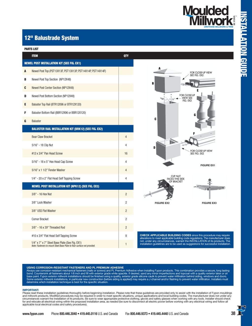
3 How to Order Remember to Order Adhesive A urethane-based adhesive must be used on all joint surfaces. See page 138 to order PL Premium Adhesive. Balustrade Systems Fypon smooth, white balustrades are available in three systems: 5," 7" and 12." This size designates the width of the top and bottom rail. For ease of ordering, we've grouped the products within these systems. In addition to these three sizes, we now offer a new stone-textured system, which has a 6"-wide top and bottom rail. Planning Your Layout Balusters For each baluster, we have noted a " " dimension, which is the maximum center-to-center distance between balusters that still does not allow a 4" ball to pass through at any point. The number of balusters you need can be found by dividing the rail span, in inches, by the center spacing dimension shown or smaller. NOTE: When dividing gives you a fractional result, always round up to the next whole number. Example BAL3X20CC requires 5" on center spacing Classic Baluster BAL3X20CC 2 1 /2" 20" 3 1 /2" 5" BAL3X28CC 2 1 /2" 28" 3 1 /2" 4 15 /16" Sample Chart Each category chart includes a product photo, part numbers and product dimensions. The accessory matches for each part are listed, if applicable. Remember to Order Adhesive A urethane-based adhesive must be used on all joint surfaces. See page 138 to order PL Premium Adhesive. Rail Installation Kit Contents Balustrade rail installation kits are sold separately. Order two kits per rail section unless otherwise specified. BRK5 Connects both ends of one 5" rail to newel, porch post or wall. Order two kits per section. Kit Contents: (2) 2" wide x 1 ½" x 2" Angle Brackets (6) #14 x 2 ½" Stainless Steel Flat-Head Screws BRK6-7 Connects both ends of one 7" rail to newel, porch post or wall. Order two kits per section. Kit Contents: (2) 4" wide x 1 ½" x 2" Angle Brackets (8) #14 x 2 ½" Stainless Steel Flat-Head Screws BRK12 Connects both ends of one 12" rail to newel or wall. Order two kits per section. Kit Contents: (4) Bear Claw Brackets (16) #12 x 3 /4" Pan-Head Screws (4) 5 /16" 18 x 5" Hex-Head Cap Screws (2) 1 /4" 20 x 2" Flat-Head Phillips Thread Cutting Screws (4) 5 /16" Clip Nuts (4) 1 1 /2" O.D. x 5 /16" I.D. x 3 /64" thick Fender Washers BRK12ANGLBKT Connects both ends of one 12" rail section (four connections) to 13" newels ONLY Kit Contents: (2) Top Bracket (2) Bottom Bracket (8) 1 /4" 20 x 3" Hex-Head Bolt (4) 5 /16" 18 x 1 1 /2" Hex-Head Bolt (8) 1 /4" 20 Hex Nut (8) 5 /16" Split Lock Washer (8) 1 /4" x 1 1 /4" Fender Washers (8) #14 x 2" Phillips Pan-Head Screw Newel Post Installation Kit Contents Newel post installation kits are sold separately from the newel posts. Fasteners to mount steel base plate to floor surface not provided. Balustrades & Columns Rail Installation Kits Each rail section (span between two newel posts) will require two rail installation kits (BRK). Rail installation kits will connect both ends of one rail to a newel post, with the exception of BRK12ANGLBKT. This kit connects both ends of one section, requiring only one kit per section. NOTE: Fypon rail installation kits will not work on stair applications. Newel Posts Each newel post will require one newel post installation kit (NPK) to anchor the base of the post, as well as any post tops, balls or trim collars desired. NPK400 Secures one 6" newel post to the floor Kit Contents: (1) Steel Base Plate (1) Channel Bracket (1) 1 /2" 13 Hex Nut (1) 1 /2" Lock Washer (1) 1 /2" 13 x 72" Threaded Rod NPK600 Secures one 8" newel post to the floor Kit Contents: (1) Steel Base Plate (1) Channel Bracket (1) 1 /2" 13 Hex Nut (1) 1 /2" Lock Washer (1) 1 /2" 13 x 72" Threaded Rod NPK10 Secures one 10" newel postto the floor Kit Contents: (1) Steel Base Plate (1) Channel Bracket (1) 1 /2" 13 Hex Nut (1) 1 /2" Lock Washer (1) 1 /2" 13 x 72" Threaded Rod NPK12 Secures one 12" newel post to the floor Kit Contents: (2) 3 /8" Hex Nuts (2) 3 /8" Lock Washers (2) 3 /8" Flat Washers (2) Corner Brackets (2) 3 /8" 16 x 40" Threaded Rods (8) #10 x 3 /4" Flat Head Self Tapping Screws (1) Steel Base Plate NPK13 Secures one 13" newel post to the floor Kit Contents: (1) Steel Base Plate (1) Channel Bracket (1) 1 /2" 13 Hex Nut (1) 1 /2" Lock Washer (1) 1 /2" 13 x 72" Threaded Rod Phone Fax U.S. and Canada 109

4 Balustrades & Columns Balustrade Systems & Columns Note: Baluster photo shown may not be an accurate representation of every size within each category. Ashley Baluster BAL2X10AY 2 1 /4" 10" 2" 5 7 /8" BAL2.5X15AY 2 1 /2" 15" 3 1 /2" 5 27 /32" BAL3X20AY 2 1 /2" 20" 2 1 /2" 5 3 /8" Rosedale Baluster BAL3X24RL 2 1 /2" 24" 3" 5 7 /16" BAL3X24AY 2 1 /2" 24" 4 1 /2" 5 3 /8" BAL3X28AY 2 1 /2" 28" 4 1 /2" 5 11 /32" BAL3X32AY 2 1 /2" 32" 4 1 /2" 5 11 /32" Square Baluster BAL3X36AY 2 1 /2" 36" 6" 5 3 /16" Classic Baluster BAL3X20CC 2 1 /2" 20" 3 1 /2" 5" BAL3X24CC 2 1 /2" 24" 3 1 /2" 4 31 /32" BAL3X28CC 2 1 /2" 28" 3 1 /2" 4 15 /16" BAL3X32CC 2 1 /2" 32" 3 1 /2" 5 1 /32 Logan Baluster BAL3X18LN 3" 18" 3" 5 19 /32" BAL3X18LNOB 3" 18" 1 1 /2" (Top) 1 3 /4" (Bottom) 5 7 /16" BAL3X20LN 3" 20" 3" 5 7 /16" BAL3X24LN 3" 24" 3" 5 7 /16" BAL3X28LN 3" 28" 3" 5 7 /16" BAL3X32LN 3" 32" 3" 5 7 /16" BAL3X36LN 3" 36" 3" 5 7 /16" BAL2X16SQ 1 3 /4" 16" 5 11 /16" BAL2X20SQ 1 3 /4" 20" 5 11 /16" BAL2X24SQ 1 3 /4" 24" 5 11 /16" BAL2X28SQ 1 3 /4" 28" 5 11 /16" BAL2X32SQ 1 3 /4" 32" 5 11 /16" BAL2X48SQ 1 3 /4" 48" 5 11 /16" Woodruff Baluster BAL3X18WF 2 1 /2" 18" 4" 5 17 /32" BAL3X20WF 2 1 /2" 20" 4" 5 7 /32" BAL3X20WFOB 2 3 /4" 20 1 /4" 3 3 /4" (Top) 4" (Bottom) 5 1 /2" BAL3X24WF 2 1 /2" 24" 4" 5 5 /32" BAL3X28WF 2 1 /2" 28" 4" 5 5 /32 BAL3X32WF 2 1 /2" 32" 4" 5 5 /32 BAL3X36WF 2 1 /2" 36" 4" 5 5 / Phone Fax U.S. and Canada


 PST3X5 Pedestal Ball Top 3 1 /2\" 3\" 4 3 /4\" PST7X7F BBRR5X60 Radius Bottom Rail 60\" 3 1 /8\"")

 TC6 Trim Collar 9 1 /8\" 5 5 /8\" 2\" NP6X48 Design Tip A variety of post options is available to customize your system.")
5 Remember to Order Adhesive A urethane-based adhesive must be used on all joint surfaces. See page 138 to order PL Premium Adhesive. *Note: Max. rail span distance for field applications is 96." BTR5X96 8' Top Rail BTR5X144* 12' Top Rail BBR5X96 8' Bottom Rail BBR5X144* 12' Bottom Rail Top & Bottom Rails Top Bottom Rail Length 4 5 /8" 3 1 /4" 3 1 /8" 96" 4 5 /8" 3 1 /4" 3 1 /8" 144" 3 3 /4" 4 1 /2" 3 1 /8" 96" 3 3 /4" 4 1 /2" 3 1 /8" 144" NP6X /2" 48" NPK400 Plain Newel Post Accessories This Page PST6X6FP PST7X7F PST7X7P TC6 Secures one 6" Newel Post to the structural substrate (Kit contents are listed on page 109) Newel Post Accessories Balustrades & Columns Radius Rails Bottom Top Accessories This Page Radius Line Length B5X7 Ball Top 4 3 /8" 5 1 /4" 6 3 /4" PST7X7F PST8X7C BTRR5X60 Radius Top Rail 60" 3 1 /8" 94 1 /2" (1/4 Circle) PST3X5 Pedestal Ball Top 3 1 /2" 3" 4 3 /4" PST7X7F BBRR5X60 Radius Bottom Rail 60" 3 1 /8" 94 1 /2" (1/4 Circle) PST6X6FP Fancy Peaked Top 7 1 /16" 2" NP6X48 RSB4X4X6 Rail Accessories PST7X7F Flat Post Top 6 1 /2" 4 1 /2" 1 1 /2" NP6X48 PST7X7P Peaked Post Top 6 1 /2" 1 1 /2" NP6X48 BRK5 Rail Installation Kit RSB4X4X6 Rail Support Installation Notes Connects both ends of one 5" top or bottom rail to support structure. Order two kits per section. (Kit contents are listed on page 109.) Install under the bottom rail at a span of 48" or less. Dimensions: 4" x 4" x 7 1 /4" (May be trimmed for height.) TC6 Trim Collar 9 1 /8" 5 5 /8" 2" NP6X48 Design Tip A variety of post options is available to customize your system. Choose from structural porch posts (page 116), structural columns (page 117) or PVC column wraps (pages ). 1 2 BTR12X144 Top Rail BAL6X24AY Ashley Baluster BBR12X144 Bottom Rail PST13X13P Peaked Cap NP12X48 Newel Post Phone Fax U.S. and Canada 111
6 Balustrades & Columns Balustrade Systems & Columns Note: Baluster photo shown may not be an accurate representation of every size within each category. Ashley Baluster BAL4X24AY 4 1 /2" 24" 4 1 /2" 7 3 /8" BAL5X20AY 4 1 /2" 20" 3 1 /2" 7 21 /32" Logan Baluster BAL4X24LN 3 1 /2" 24" 1 3 /4" (Top) 2" (Bottom) 5 15 /16" BAL5X31LN 4 1 /2" 31" 3 1 /2" 5 15 /16" BAL5X24AY 4 1 /2" 24" 3 1 /2" 7 3 /8" BAL5X28AY 4 1 /2" 28" 4 1 /2" 7 11 /32" BAL5X32AY 4 1 /2" 32" 4 1 /2" 7 11 /32" Rosedale Baluster Beaumont Baluster BAL5X16RL 4 1 /2" 16" 4" 7 1 /4" BAL5X20RL 4 1 /2" 20" 4" 6 21 /32" BAL4X22BE 4" 22" BAL5X19BE 5 1 /4" 19 1 /8" 1 1 /8" (Top) 1 3 /4" (Bottom) 1 1 /8" (Top) 1 3 /4" (Bottom) 6 9 /32" 6 23 /32" BAL5X24RL 4 1 /2" 24" 4" 6 21 /32" BAL5X24RLOB 4 1 /2" 24" 3" (Top) 4" (Bottom) 6 3 /16" BAL5X28RL 4 1 /2" 28" 4" 6 21 /32" BAL5X22BE 5" 22" 2 1 /8" (Top) 3 3 /4" (Bottom) 7 5 /32" Square Baluster Classic Baluster BAL5X28SQ 4 7 /8" 28" 8 13 /16" BAL4X27CCOB 4 1 /4" 27" 4" 5 13 /16" BAL4X31CCOB 4 1 /4" 31" 4" 5 11 /16" BAL5X28CCOB 4 1 /2" 28" 3 3 /8" 5 29 /32" BAL5X20CC 5" 20" 4 1 /2" 7 21 /32" BAL5X24CC 5" 24" 5" 7 21 /32" BAL5X28CC 5" 28" 5" 7 1 /2" BAL5X30CC 5" 30 1 /2" 5" 7 17 /32" Woodruff Baluster BAL5X20WF 4 1 /2" 20" 4" 7 3 /16" BAL5X24WF 4 1 /2" 24" 4" 7 5 /32" BAL5X28WF 4 1 /2" 28" 4" 7 5 /32" BAL5X32WF 4 1 /2" 32" 4" 7 5 /32" Phone Fax U.S. and Canada


 Newel Post Accessories Balustrades & Columns BRK6-7 Rail Installation Kit RSB4X4X6 Rail Support RSB4X4X6 Installation Notes Rail Accessories Connects both ends of one 7\" top or bottom rail to")
7 Remember to Order Adhesive A urethane-based adhesive must be used on all joint surfaces. See page 138 to order PL Premium Adhesive. *Note: Max. rail span distance for field applications is 96." BTR7X96 8' Top Rail BTR7X120* 10' Top Rail BTR7X144* 12' Top Rail BBR7X96 8' Bottom Rail BBR7X120* 10' Bottom Rail BBR7X144* 12' Bottom Rail Top & Bottom Rails Top Bottom Rail Length 7" 5 1 /2" 5 1 /4" 96" 7" 5 1 /2" 5 1 /4" 120" 7" 5 1 /2" 5 1 /4" 144" 5 1 /2" 7" 5 1 /4" 96" 5 1 /2" 7" 5 1 /4" 120" 5 1 /2" 7" 5 1 /4" 144" Post Top Sold Separately NPCP8X48 Corner Panel Newel Post NPSP8X48 Straight Panel Newel Post NPK600 Newel Installation Kit Panel Newel Post Top View Accessories This Page 8" 8" 47 3 /4" 47 3 /4" PST9X9FP PST10X10P PST10X10F TC8-8 Secures one 8" newel post to the structural substrate. (Kit contents are listed on page 109.) Newel Post Accessories Balustrades & Columns BRK6-7 Rail Installation Kit RSB4X4X6 Rail Support RSB4X4X6 Installation Notes Rail Accessories Connects both ends of one 7" top or bottom rail to support structure. (Kit contents are listed on page 109.) Install under the bottom rail at a span of 48" or less. Dimensions: 4" x 4" x 7 1 /4" (May be trimmed for height.) Bottom Top B5X7 Ball Top PST3X5 Pedestal Ball Top PST8X8FP Fancy Peaked Top Accessories This Page 4 3 /8" 5 1 /4" 6 3 /4" PST10X10F 3 1 /2" 3" 4 3 /4" PST10X10F 9 3 /8" 3" NP8X48 Plain Newel Post PST9X9FP Fancy Peaked Top 10 3 /8" 3" NPCP8X48 NPSP8X48 NP8X48 Newel Post NPK600 Newel Installation Kit 7 1 /2" 48" Secures one 8" newel post to the structural substrate. (Kit contents are listed on page 109.) Accessories This Page PST8X8FP PST10X10P PST10X10F TC8 Decorative Newel Post PST10X10F Flat Post Top PST10X10P Peaked Post Top PST11X11FP Fancy Peaked Top PST12X12F Flat Post Top 9 1 /2" 6 1 /4" 2" 9 1 /2" 3" NP8X48 NPCP8X48 NPSP8X48 NP8X48 NPCP8X48 NPSP8X /32" 4 1 /2" NP10X /16" 10 1 /2" 1 5 /16" NP10X48 Post Top Sold Separately NP10X48 Newel Post NPK10 Newel Installation Kit 10" 48" Secures one 10" newel post to the structural substrate. (Kit contents are listed on page 109.) Accessories This Page PST11X11FP PST12X12F TC8 Trim Collar TC8-8 Trim Collar 11 1 /8" 7 5 /8" 2" NP8X /8" 8 1 /8" 2" NPCP8X48 NPSP8X48 Phone Fax U.S. and Canada 113
8 Balustrades & Columns Balustrade Systems & Columns Note: Baluster photo shown may not be an accurate representation of every size within each category. Ashley Baluster BAL6X24AY 5 1 /2" 24" 4 1 /2" 8 3 /8" Rosedale Baluster BAL5X16RL 4 1 /2" 16" 4" 7 1 /4" BAL5X20RL 4 1 /2" 20" 4" 6 21 /32" Beaumont Baluster BAL5X24RL 4 1 /2" 24" 4" 6 21 /32" BAL5X24RLOB 4 1 /2" 24" 3" (Top) 4" (Bottom) 6 3 /16" BAL5X28RL 4 1 /2" 28" 4" 6 21 /32" BAL5X19BE 5 1 /4" 19 1 /8" 1 1 /8" (Top) 1 3 /4" (Bottom) 6 23 /32" BAL7X25RL 6 3 /4" 24 1 /2" 3" (Top) 4 1 /2" (Bottom) 6 15 /16" BAL5X22BE 5" 22" 2 1 /8" (Top) 3 3 /4" (Bottom) 7 5 /32" BAL7X28RL 6 3 /4" 28" 6" 8 29 /32" BAL5X31BE 5 3 /4" 31" BAL5X34BE 5 3 /4" 33 7 /8" 2 17 /32" (Top) 4 1 /32" (Bottom) 3 31 /32" (Top) 5 15 /32" (Bottom) 6 27 /32" 6 7 /8" Square Baluster BAL6X22BE 6 3 /16" 21 7 /8" 2 1 /16" (Top) 3 11 /16" (Bottom) 7 15 /16" Classic Baluster BAL5X28SQ 4 7 /8" 28" /16" Woodruff Baluster BAL7X24CC 7" 24" 6" 9 15 /32" BAL7X28CC 7" 28" 6" 9 3 /8" BAL7X28CCOB 7" 28" 3 13 /32" 7 17 /32" BAL5X20WF 4 1 /2" 20" 4" 7 3 /16" BAL5X24WF 4 1 /2" 24" 4" 7 5 /32" BAL5X28WF 4 1 /2" 28" 4" 7 5 /32" BAL5X32WF 4 1 /2" 32" 4" 7 5 /32" BAL6X28WF 5 1 /2" 28" 4" 8 5 /32" Phone Fax U.S. and Canada


 BAL7X25RL Connects both ends of one 12\" top and bottom Rail to BRK12ANGLBKT Baluster Reinforced 13\" newel post ONLY - Order one kit per section.")

9 Remember to Order Adhesive A urethane-based adhesive must be used on all joint surfaces. See page 138 to order PL Premium Adhesive. BTR12X96 8' Top Rail BTR12X120* 10' Top Rail Top & Bottom Rails Top Bottom Rail Length 11 7 /8" 9" 5 1 /4" 96" 11 7 /8" 9" 5 1 /4" 120" NPCP13X48 Corner Panel Newel NPSP13X48 Straight Panel Newel Panel Newel Post 12 1 /2" 47 3 /4" 12 1 /2" 47 3 /4" Top View Accessories This Page PST13X13FP PST14X14F PST14X14P Balustrades & Columns BTR12X144* 12' Top Rail 11 7 /8" 9" 5 1 /4" 144" Post Top Sold Separately NPK13 Newel Installation Kit Secures one 13" newel post to the structural substrate. (Kit contents are listed on page 109.) BBR12X96 8' Bottom Rail BBR12X120* 10' Bottom Rail 9" 11 7 /8" 5 1 /4" 96" 9" 11 7 /8" 5 1 /4" 120" Newel Post Accessories *Note: Max. rail span distance for field applications is 96." BBR12X144* 12' Bottom Rail 9" 11 7 /8" 5 1 /4" 144" Bottom Top Accessories This Page RSB4X4X6 Rail Accessories B10X13 Ball Top PST13X13F Flat Post Top 8 7 /16" 10" 12 7 /8" 12 1 /2" 8 21 /32" 1 1 /2" PST13X13F PST14X14F B10X13 NP12X48 BRK12 Rail Installation Kit Installation Notes Connects both ends of one 12" top or bottom rail to 12" newel post or other support. Order two kits per section. (Kit contents are listed on page 109.) BAL7X25RL Connects both ends of one 12" top and bottom Rail to BRK12ANGLBKT Baluster Reinforced 13" newel post ONLY - Order one kit per section. Rail Installation Kit (Kit contents are listed on page 109.) RSB4X4X6 Rail Support Install under the Bottom Rail at a span of 48" or less. Dimensions: 4" x 4" x 7 1 /4" (May be trimmed for height.) PST13X13FP Fancy Peaked Top PST13X13P Peaked Post Top PST14X14F Flat Post Top 13 1 /4" 4 19 /32" NP12X48 NPCP13X48 NPSP13X /2" 1 1 /2" NP12X48 14" 8 11 /16" 3 1 /8" B10X13 NPCP13X48 NPSP13X48 Newel Post PST14X14P Peaked Post Top 14" 5" NPCP13X48 NPSP13X48 Accessories This Page NP12X48 3-pc Newel Post 12" 48" 12" PST13X13FP PST13X13F PST13X13P PST14X14X3P NPK12 Newel Installation Kit Secures one 13" newel post to the structural substrate. (Kit contents are listed on page 109.) Phone Fax U.S. and Canada 115


10 Balustrades & Columns Stone Balustrade System & Columns Balustrade Systems & Columns Note: Baluster photo shown may not be an accurate representation of every size within each category. Euro Stone Baluster Stone Balustrade System Half Round Column Kit Stone Balustrade System Projection HRC15X168ST 15" / 16" 7 1 / 2" BAL5X28EUST 5 11 /32" /32" 7 5 /8" Top & Bottom Rails Stone Balustrade System Ships in four pieces: (1) Cap Half (1) Shaft Top Half (1) Shaft Bottom Half (1) Base Half Kit ships in four pieces and creates a single half column. Order two kits to create a full column. BTR6X96ST 8' Top Rail BTR6X120ST 10' Top Rail BBR6X96ST 8' Bottom Rail BBR6X120ST 10' Bottom Rail Top Bottom Rail Length 6" 4 1 / 2" 4" 96" 6" 4 1 / 2" 4" 120" 6 7 / 32" 5 7 / 32" 4 27 / 32" 96" 6 7 / 32" 5 7 / 32" 4 27 / 32" 120" Newel Post Stone Balustrade System Projection HRCBCC96X12ST 22 3 / 8" / 4" 11 3 / 4" Ships in three pieces: (1) Cap Half (1) Shaft Half (1) Base Half Half Round Column Kit Stone Balustrade System Accessories This Page Kit ships in three pieces and creates a single half column. Order two kits to create a full column. NP8X48ST 8" 48" 12" PST10X10PST NPK600 Newel Installation Kit Secures one 8" newel post to the structural substrate. (Kit contents are listed on page 109.) Post Top Stone Balustrade System PST10X10PST 5 11 /32" 3" Phone Fax U.S. and Canada
 Baluster Top Rail (BTR5X96 or BTR5X144) Baluster Baluster Bottom Rail (BBR5X96 or BBR5X144) Rail Support (RSB4X4X6) Post Top (PST7X7P shown")
11 PARTS LIST ITEM QTY A PORCH POST INSTALLATION KIT (PPK6) (SEE STEP 3C) 5 1/2" x 5 1/2" Trim Collar 2 2" Wide x 1 1/2" x 2" Angle Bracket 4 MATERIALS NEEDED INSTALLATION GUIDE #14 x 2 1/2" Stainless Steel Flat Head Screw 12 B C D E F G H Porch Post (PP6X96) Baluster Top Rail (BTR5X96 or BTR5X144) Baluster Baluster Bottom Rail (BBR5X96 or BBR5X144) Rail Support (RSB4X4X6) Post Top (PST7X7P shown or PST7X7F) Newel Post (NP6X48) J BALUSTER RAIL INSTALLATION KIT (BRK5) (SEE STEPS 5A, 5B) 2" Wide x 1 1/2" x 2" Angle Bracket 2 #14 x 2 1/2" Stainless Steel Flat Head Screw 6 K NEWEL POST INSTALLATION KIT (NPK6) (SEE STEPS 4A, 4B, 4C) 3/8" - 16 Hex Nut 2 3/8" Lock Washer 2 3/8" USS Flat Washer 2 1/4" x 4 1/2" Diameter Steel Top Mounting Plate 1 3/8" - 16 x 50" Threaded Rod 2 The has been tested and meets the following BOCA National Building Code/1993 Criteria if assembled according to manufacturer s guidelines: 1/4" x 3 1/2" x 3 1/2" Steel Base Plate Note: Fasteners to mount Steel Base Plate to floor surface not provided Guard Design and Construction In-Fill Areas L OPTIONAL DECORATIVE TRIM COLLAR (TC6) 5 1/2" x 5 1/2" Trim Collar 1 CHECK APPLICABLE BUILDING CODES since this procedure may require alterations to meet applicable building code regulations. The manufacturer does not, under any circumstances, warrant the INSTALLATION of its products. The installation guidelines are to be used as suggestions for successful installation. USING CORROSION-RESISTANT FASTENERS AND PL PREMIUM ADHESIVE Always use corrosion-resistant mechanical fasteners (nails or screws) and PL Premium Adhesive when installing Fypon products. This combination provides a secure, long lasting bond. Countersink all fasteners about 1/8 inch and fill with exterior grade white spackle. If desired, sand any minor imperfections and topcoat with a quality exterior latex or oil base paint. Fypon exterior millwork installations should be finished using a quality, exterior grade silicone caulk to prevent water infiltration behind siding, windows and doors. Some exterior millwork installations, in particular new construction (before siding is applied) may require a J-channel and/or flashing to prevent water infiltration. Installers must determine which installation technique is best for the specific situation. IMPORTANT: Please read these installation guidelines thoroughly before beginning installation. Please note that these guidelines are provided only to assist with the installation of Fypon mouldings and millwork products. Modified procedures may be required in order to meet specific situations, unique applications and local building codes. The manufacturer does not under any circumstances warrant the installation of its products. Be sure to wear appropriate protective clothing, gloves and safety glasses when working with any tools. Installer should check for and relocate all electrical wiring within the proposed installation area, as needed (be sure to disconnect all electric power before working with any electrical wiring and follow all applicable local electrical codes and safety procedures). Phone U.S. and Canada Fax U.S. and Canada 32
 (Includes Installation Kit) Baluster Top Rail (BTR6X96 or BTR6X144) Baluster Baluster Bottom Rail (BBR6X96 or BBR6X144) Rail Support")
12 INSTALLATION GUIDE 6" Balustrade System PARTS LIST ITEM QTY A PORCH POST INSTALLATION KIT (INCLUDED WITH PORCH POST, SEE STEP 3C) Galvanized Column Mounting Plate 2 #14 x 2" Stainless Steel Sheet Metal Screw 4 MATERIALS NEEDED B C D E F G H Porch Post (PP8X96) (Includes Installation Kit) Baluster Top Rail (BTR6X96 or BTR6X144) Baluster Baluster Bottom Rail (BBR6X96 or BBR6X144) Rail Support (RSB4X4X6) Post Top (PST10X10P shown or PST10X10F) Newel Post (NP8X48) J BALUSTER RAIL INSTALLATION KIT (BRK6-7) (SEE STEPS 5A, 5B ) 4" Wide x 1 1/2" x 2" Angle Bracket 2 #14 x 2 1/2" Stainless Steel Flat Head Screw 8 K NEWEL POST INSTALLATION KIT (NPK8 - NPK10) (SEE STEPS 4A, 4B, 4C) 3/8" - 16 Hex Nut 2 3/8" Lock Washer 2 3/8" USS Flat Washer 2 1/4" x 6 1/2" Diameter Steel Top Mounting Plate 1 3/8" - 16 x 50" Threaded Rod 2 1/4" x 3 1/2" x 3 1/2" Steel Base Plate Note: Fasteners to mount Steel Base Plate to floor surface not provided. 1 L OPTIONAL DECORATIVE TRIM COLLAR (TC8) 7 1/2" x 7 1/2" Trim Collar CHECK APPLICABLE BUILDING CODES since this procedure may require alterations to meet applicable building code regulations. The manufacturer does not, under any circumstances, warrant the INSTALLATION of its products. The installation guidelines are to be used as suggestions for successful installation. USING CORROSION-RESISTANT FASTENERS AND PL PREMIUM ADHESIVE Always use corrosion-resistant mechanical fasteners (nails or screws) and PL Premium Adhesive when installing Fypon products. This combination provides a secure, long lasting bond. Countersink all fasteners about 1/8 inch and fill with exterior grade white spackle. If desired, sand any minor imperfections and topcoat with a quality exterior latex or oil base paint. Fypon exterior millwork installations should be finished using a quality, exterior grade silicone caulk to prevent water infiltration behind siding, windows and doors. Some exterior millwork installations, in particular new construction (before siding is applied) may require a J-channel and/or flashing to prevent water infiltration. Installers must determine which installation technique is best for the specific situation. IMPORTANT: Please read these installation guidelines thoroughly before beginning installation. Please note that these guidelines are provided only to assist with the installation of Fypon mouldings and millwork products. Modified procedures may be required in order to meet specific situations, unique applications and local building codes. The manufacturer does not under any circumstances warrant the installation of its products. Be sure to wear appropriate protective clothing, gloves and safety glasses when working with any tools. Installer should check for and relocate all electrical wiring within the proposed installation area, as needed (be sure to disconnect all electric power before working with any electrical wiring and follow all applicable local electrical codes and safety procedures) Phone U.S. and Canada Fax U.S. and Canada
 (Includes Installation Kit) Baluster Top Rail (BTR7X96, BTR7X120 or BTR7X144) Baluster Baluster Bottom Rail (BBR7X96, BBR7X120 or BBR7X144) Rail Support")
13 PARTS LIST ITEM QTY A PORCH POST INSTALLATION KIT (INCLUDED WITH PORCH POST, SEE STEP 3C) Galvanized Column Mounting Plate 2 #14 x 2" Stainless Steel Sheet Metal Screw 4 MATERIALS NEEDED INSTALLATION GUIDE B C D E F G H Porch Post (PP8X96) (Includes Installation Kit) Baluster Top Rail (BTR7X96, BTR7X120 or BTR7X144) Baluster Baluster Bottom Rail (BBR7X96, BBR7X120 or BBR7X144) Rail Support (RSB4X4X6) Post Top (PST10X10P shown or PST10X10F) Newel Post (NP8X48) J BALUSTER RAIL INSTALLATION KIT (BRK6-7) (SEE STEPS 5A, 5B ) 4" Wide x 1 1/2" x 2" Angle Bracket 2 #14 x 2 1/2" Stainless Steel Flat Head Screw 8 K NEWEL POST INSTALLATION KIT (NPK8 - NPK10) (SEE STEPS 4A, 4B, 4C) 3/8" - 16 Hex Nut 2 3/8" Lock Washer 2 3/8" USS Flat Washer 2 1/4" x 6 1/2" Diameter Steel Top Mounting Plate 1 3/8" - 16 x 50" Threaded Rod 2 1/4" x 3 1/2" x 3 1/2" Steel Base Plate Note: Fasteners to mount Steel Base Plate to floor surface not provided. 1 L OPTIONAL DECORATIVE TRIM COLLAR (TC8) 7 1/2" x 7 1/2" Trim Collar CHECK APPLICABLE BUILDING CODES since this procedure may require alterations to meet applicable building code regulations. The manufacturer does not, under any circumstances, warrant the INSTALLATION of its products. The installation guidelines are to be used as suggestions for successful installation. USING CORROSION-RESISTANT FASTENERS AND PL PREMIUM ADHESIVE Always use corrosion-resistant mechanical fasteners (nails or screws) and PL Premium Adhesive when installing Fypon products. This combination provides a secure, long lasting bond. Countersink all fasteners about 1/8 inch and fill with exterior grade white spackle. If desired, sand any minor imperfections and topcoat with a quality exterior latex or oil base paint. Fypon exterior millwork installations should be finished using a quality, exterior grade silicone caulk to prevent water infiltration behind siding, windows and doors. Some exterior millwork installations, in particular new construction (before siding is applied) may require a J-channel and/or flashing to prevent water infiltration. Installers must determine which installation technique is best for the specific situation. IMPORTANT: Please read these installation guidelines thoroughly before beginning installation. Please note that these guidelines are provided only to assist with the installation of Fypon mouldings and millwork products. Modified procedures may be required in order to meet specific situations, unique applications and local building codes. The manufacturer does not under any circumstances warrant the installation of its products. Be sure to wear appropriate protective clothing, gloves and safety glasses when working with any tools. Installer should check for and relocate all electrical wiring within the proposed installation area, as needed (be sure to disconnect all electric power before working with any electrical wiring and follow all applicable local electrical codes and safety procedures). Phone U.S. and Canada Fax U.S. and Canada 34

14 INSTALLATION GUIDE 5", 6" and s INSTALLATION INSTRUCTIONS STEP 2B 1. INITIAL LAYOUT Mark layout lines on floor surface where all PORCH POSTS and NEWEL POSTS will be located. Allow dimensions for the layout of both NEWEL POSTS and PORCH POSTS. Note: This layout is important in order to get accurate measurements for the actual length of each TOP and BOTTOM RAIL. 2. BUILD UP AND ASSEMBLE RAIL SECTIONS To speed up field installations, build up and assemble the BALUSTRADE RAIL SECTIONS in a shop setting when possible. Follow up with easy installation between the supporting posts out on the job site. A) Using accurate field measurements (taken in Step 1) cut the matching TOP and BOTTOM RAILS to length for each respective section. B) Lay out and mark center lines on RAILS. Mark BALUSTER positions then drill holes to accept BALUSTERS. The diameter of the drilled holes will vary according to the BALUSTRADE size. Tip: A drill press with standard woodworking drill bits works well for drilling these holes. C) Apply a 1/4" bead of urethane base construction adhesive on each end of BALUSTER. Then insert BALUSTER into the drilled TOP and BOTTOM RAIL. D) Lay the RAIL ASSEMBLY on a flat surface. Use strap clamps as needed to draw RAIL ASSEMBLY together. Clamp tightly and allow the adhesive to set up. (This usually takes a minimum of 12 hours.) As the RAIL ASSEMBLY is drying, before it sets up, make sure it is square and that the BALUSTERS are square to the RAIL SECTION. Clean off any excess adhesive with a putty knife before the adhesive sets. Do not handle the newly assembled RAIL SECTIONS until the adhesive has cured completely. If painting is desired, a good time to paint the RAIL SECTIONS would be now, before field assembly begins. STEP 1 STEP 2C STEP 2D 3. INSTALL PORCH POSTS FOR PP6X96 ONLY A) The PORCH POST is a load bearing support post. It can be trimmed to various heights in the top or bottom flat post areas without affecting the integrity of the POST. However, the PORCH POST has a steel pipe molded into the center which must be cut with a hack saw or Sawzall reciprocating saw with metal cutting blades. STEP 3A STEP 3B B) Slide TRIM COLLARS along POST. C) Install the 2" wide x 1 1/2" x 2" angle brackets as shown in Fig. 3C. Drill 1/8" x 2 1/2" pilot hole for #14 x 2 1/2" stainless steel flat head screws. (Masonry fasteners not included.) Then slide TRIM COLLARS over the brackets. Secure with adhesive and trim nails. FOR PP8X96 ONLY A) Determine the required height of the PORCH POST by carefully measuring the distance from the floor to the bottom of the porch overhang or other structure being supported. STEP 3C B) Fypon PORCH POST are trimmed for height at the bottom. Transfer the measurement from Step One, above, marking all the way around the base of the POST. Carefully cut the polymer shell of the POST using a circular saw or hand saw, being careful to not cut into the steel reinforcement. Then cut through the steel reinforcement using a hack saw or power reciprocating saw with a steel cutting blade. INSTALLATION INSTRUCTIONS CONTINUED ON FOLLOWING PAGE. USING CORROSION-RESISTANT FASTENERS AND PL PREMIUM ADHESIVE Always use corrosion-resistant mechanical fasteners (nails or screws) and PL Premium Adhesive when installing Fypon products. This combination provides a secure, long lasting bond. Countersink all fasteners about 1/8 inch and fill with exterior grade white spackle. If desired, sand any minor imperfections and topcoat with a quality exterior latex or oil base paint. Fypon exterior millwork installations should be finished using a quality, exterior grade silicone caulk to prevent water infiltration behind siding, windows and doors. Some exterior millwork installations, in particular new construction (before siding is applied) may require a J-channel and/or flashing to prevent water infiltration. Installers must determine which installation technique is best for the specific situation. IMPORTANT: Please read these installation guidelines thoroughly before beginning installation. Please note that these guidelines are provided only to assist with the installation of Fypon mouldings and millwork products. Modified procedures may be required in order to meet specific situations, unique applications and local building codes. The manufacturer does not under any circumstances warrant the installation of its products. Be sure to wear appropriate protective clothing, gloves and safety glasses when working with any tools. Installer should check for and relocate all electrical wiring within the proposed installation area, as needed (be sure to disconnect all electric power before working with any electrical wiring and follow all applicable local electrical codes and safety procedures) Phone U.S. and Canada Fax U.S. and Canada

15 5", 6" and s (continued) INSTALLATION INSTRUCTIONS C) After cutting through the steel tubing, pre-drill holes approximately 3/4" up from the bottom of the POST using a 13/64" drill bit. These holes should enter the side of the POST at a right angle and go through both the polymer shell and the steel reinforcement. Now use a 1/2" drill bit to expand the drill holes through the polymer only (do not drill through the steel reinforcement) using the 13/64" holes as pilot holes. These 1/2" holes will allow the screw head to go all the way to the steel reinforcement. Repeat this process at the top of the POST, pre-drilling holes approximately ¾ from the top and centered on the top side. D) Paint all exposed steel at both the top and bottom of the POST, using a quality, zinc base primer spray paint (Rust-Oleum, etc.) to help prevent corrosion. STEP 4A INSTALLATION GUIDE E) Determine the proper location for top and bottom column mounting plates. Be careful to mark these locations precisely, so that the top and bottom plates line up directly above and below each other. Identify the correct location of the top plate first, and use a plumb line dropped from the center point of the top plate location to accurately align the center point location for the bottom column mounting plate. F) Install the top and bottom column mounting plates using corrosion resistant mechanical fasteners. For anchoring into wooden floors, ceilings and other structures, stainless steel flat head screws are recommended. For installation into concrete, stone or other floor and ceiling materials, appropriate masonry and/or other fasteners must be used. G) Set the POST into place beneath the top anchor. Lift (jack) the upper structure just high enough to allow the POST to be set into place above the bottom anchor. H) Use the 13/64" holes drilled in Step 3 as guide holes to drill 13/64" holes through the column mounting plates. Firmly attach the POST to the top and bottom plates, driving the corrosion resistant screws provided all the way in so that their heads are flush against the steel tubing (four screws provided, two for the top plate and two for the bottom). I) Patch screw holes using a quality exterior grade, non-shrinking wood filler. Once the filler has dried, lightly sand any minor imperfections and paint the POST as desired using a quality exterior grade latex or oil base paint. 4. INSTALL NEWEL POSTS A) the steel BASE MOUNTING PLATE within layout lines marked out in Step 1. Mount them securely to floor surface (fasteners to mount to floor surface not provided). Install and tighten the two 3/8"-16 x 50" THREADED RODS into MOUNTING PLATE. B) The NEWEL POST may be trimmed to a desired height (measure and cut from the unrouted end of the POST). Add a centered saw kerf to the bottom of the newel post for water drainage. To install the POST align the POST over the THREADED RODS. Install the steel TOP MOUNTING PLATE over the THREADED RODS into the recessed cavity of the NEWEL POST TOP which is routed to accept the hardware. Install 3/8" flat and lock washers and tighten with 3/8" nuts to100 in./lbs. torque. C) TRIM COLLARS may be used on the bottom of the NEWEL POSTS to add a finishing touch. (SEE PARTS LISTS.) Slide the COLLARS over the top of the NEWEL POST into position before the NEWEL POST TOP is fastened in place. D) Finish NEWEL POST by attaching NEWEL POST TOP. Apply urethane base construction adhesive then nail or screw TOP into position. INSTALLATION INSTRUCTIONS CONTINUED ON FOLLOWING PAGE. STEP 4B STEP 4C USING CORROSION-RESISTANT FASTENERS AND PL PREMIUM ADHESIVE Always use corrosion-resistant mechanical fasteners (nails or screws) and PL Premium Adhesive when installing Fypon products. This combination provides a secure, long lasting bond. Countersink all fasteners about 1/8 inch and fill with exterior grade white spackle. If desired, sand any minor imperfections and topcoat with a quality exterior latex or oil base paint. Fypon exterior millwork installations should be finished using a quality, exterior grade silicone caulk to prevent water infiltration behind siding, windows and doors. Some exterior millwork installations, in particular new construction (before siding is applied) may require a J-channel and/or flashing to prevent water infiltration. Installers must determine which installation technique is best for the specific situation. IMPORTANT: Please read these installation guidelines thoroughly before beginning installation. Please note that these guidelines are provided only to assist with the installation of Fypon mouldings and millwork products. Modified procedures may be required in order to meet specific situations, unique applications and local building codes. The manufacturer does not under any circumstances warrant the installation of its products. Be sure to wear appropriate protective clothing, gloves and safety glasses when working with any tools. Installer should check for and relocate all electrical wiring within the proposed installation area, as needed (be sure to disconnect all electric power before working with any electrical wiring and follow all applicable local electrical codes and safety procedures). Phone U.S. and Canada Fax U.S. and Canada 36

 Fasten bottom ANGLE BRACKET to underside of RAIL SECTION using one screw. C) Apply urethane base construction adhesive to the ends of RAIL that come in contact with POST.")


16 INSTALLATION GUIDE 5", 6" and s (continued) INSTALLATION INSTRUCTIONS STEP INSTALL 5" RAIL SECTIONS With all POSTS in position, screw ANGLE BRACKETS to the POST or wall surface. Drill 1/8" x 2 1/2" pilot hole for screws. The RAIL ASSEMBLY is positioned snugly between the POSTS and secured in place using the same ANGLE BRACKETS. This step requires three stainless steel flat head screws (#14 x 2 1/2"). A) Determine height of RAIL and fasten top ANGLE BRACKET securely to POST using two screws. B) Fasten bottom ANGLE BRACKET to underside of RAIL SECTION using one screw. C) Apply urethane base construction adhesive to the ends of RAIL that come in contact with POST. Position RAIL ASSEMBLY between POST and install remaining screws. STEP 5-3A STEP 5-1A STEP 5-1B STEP 5-2A STEP 5-2B 5-2. INSTALL 6" RAIL SECTIONS With all POSTS in position, screw ANGLE BRACKETS to the POST or wall surface. Drill 1/8" x 2 1/2" pilot hole for screws. The RAIL ASSEMBLY is positioned snugly between the POSTS and secured in place using the same ANGLE BRACKETS. This step requires three stainless steel flat head screws (#14 x 2 1/2"). A) Determine height of RAIL and fasten top ANGLE BRACKET securely to POST using two screws. B) Fasten bottom ANGLE BRACKET to underside of RAIL SECTION using one screw. C) Apply urethane base construction adhesive to the ends of RAIL that come in contact with POST. Position RAIL ASSEMBLY between POST and install remaining screws INSTALL 7" RAIL SECTIONS With all POSTS in position, screw ANGLE BRACKETS to the POST or wall surface. Drill 1/8" x 2 1/2" pilot hole for screws. The RAIL ASSEMBLY is positioned snugly between the POSTS and secured in place using the same ANGLE BRACKETS. This step requires three stainless steel flat head screws (#14 x 2 1/2"). A) Determine height of RAIL and fasten top ANGLE BRACKET securely to POST using two screws. B) Fasten bottom ANGLE BRACKET to underside of RAIL SECTION using one screw. C) Apply urethane base construction adhesive to the ends of RAIL that come in contact with POST. Position RAIL ASSEMBLY between POST and install remaining screws. 6. RAIL SUPPORT BLOCKS RAIL SUPPORT BLOCKS should be placed under the BOTTOM RAIL at a span of every 48" or less. These blocks can be trimmed for height. 7. FINISHING All exposed fastener heads should be countersunk and filled with automotive body filler (example: Bondo). Allow filler to cure then sand flush to the millwork surface. Caulk any gaps with a good quality exterior caulk. Any good quality latex or oil base paint can be applied over the factory finish. STEP 6 STEP 5-3B USING CORROSION-RESISTANT FASTENERS AND PL PREMIUM ADHESIVE Always use corrosion-resistant mechanical fasteners (nails or screws) and PL Premium Adhesive when installing Fypon products. This combination provides a secure, long lasting bond. Countersink all fasteners about 1/8 inch and fill with exterior grade white spackle. If desired, sand any minor imperfections and topcoat with a quality exterior latex or oil base paint. Fypon exterior millwork installations should be finished using a quality, exterior grade silicone caulk to prevent water infiltration behind siding, windows and doors. Some exterior millwork installations, in particular new construction (before siding is applied) may require a J-channel and/or flashing to prevent water infiltration. Installers must determine which installation technique is best for the specific situation. IMPORTANT: Please read these installation guidelines thoroughly before beginning installation. Please note that these guidelines are provided only to assist with the installation of Fypon mouldings and millwork products. Modified procedures may be required in order to meet specific situations, unique applications and local building codes. The manufacturer does not under any circumstances warrant the installation of its products. Be sure to wear appropriate protective clothing, gloves and safety glasses when working with any tools. Installer should check for and relocate all electrical wiring within the proposed installation area, as needed (be sure to disconnect all electric power before working with any electrical wiring and follow all applicable local electrical codes and safety procedures) Phone U.S. and Canada Fax U.S. and Canada
17
18
19
20

21
INSTALLATION GUIDE. 5" Balustrade System
 5" Balustrade System PARTS LIST ITEM QTY A PORCH POST INSTALLATION KIT (PPK6) (SEE STEP 3C) 5 1/2" x 5 1/2" Trim Collar 2 2" Wide x 1 1/2" x 2" Angle Bracket 4 MATERIALS NEEDED INSTALLATION GUIDE #14 x
Balustrades & Columns Systems
 Balustrades & Columns Systems Balustrade Systems... 163 7" Balustrade Systems... 167 12" Balustrade Systems... 172 Stone Balustrade Systems... 176 Define Your Boundaries This design accent is excellent
PVC Column Wraps - Semi-Assembled INSTALLATION INSTRUCTIONS
 - Semi-Assembled INSTALLATION INSTRUCTIONS Page 1 of 2 Materials Needed Safety Glasses Pencil Tape Measure Miter, Jig or Skill Saw Combination Square Hammer or Air Nailer Nail Countersink Flat Head Fasteners
GENERAL INSTALLATION GUIDE: WARRANTY: PRODUCT INFORMATION T F
 GENERAL INSTALLATION GUIDE: Unless otherwise indicated, all Seven Oaks M.U. Architectural Products materials are to be used for decorative purposes only. All products must be installed using ample amount
Balustrade Systems / Installation Instructions
 A. PARTS AND SUPPLIES NEEDED FOR INSTALLATION Hardware included for each 10 section of rail: 2 3 x 1-1/2 L-brackets 4 1-3/4 x 3/16 Blue hex-head screws for anchoring the L-brackets to the newel cap, column
Installation of Balustrade Systems
 Installation of Balustrade Systems IMPORTANT: Be sure to mark the center point of each newel post's location prior to installation to insure proper spacing. All product interfaces must use PL Premium Adhesive
Balustrade System Installation - Cambridge & Huntington
 A. PARTS AND SUPPLIES NEEDED FOR INSTALLATION Hardware included for each 10 section of rail: 2 3 x 1-1/2 L-brackets 4 1-3/4 x 3/16 Blue hex-head screws for anchoring the L-brackets to the newel cap, column
Installation Instructions for. Before You Begin TOOLS REQUIRED
 Composite Railing System STEP-BY-STEP Installation Instructions for Spectrum Composite Railing Virtually maintenance free 20-year warranty EverNew Spectrum Railing system is designed to work with a number
Endura-Stone Installation Instructions
 Endura-Stone Installation Instructions 1. Measure the total distance from the bottom of the beam to the platform. 2. Using a jack and post, jack up the beam only enough to remove the sting post, no more
Stair Parts Installation. Tricks
 Stair Parts Installation Tips & Tricks Introduction Your DIY staircase guide Welcome to the Stairpart home installation guide. Your stairway is both a functional and focal point in your home, so keeping
Salter Industries Spiral Stair
 Salter Industries Spiral Stair The Leader in Spiral Staircases Continuous Sleeve Stair Installation Instructions TOOLS NEEDED: 1. Electric drill with hex chuck and Phillips bit 2. Drill bits 1/8", 1/4",
installation care & maintenance instructions lifecycledecking.com 25-year limited residential warranty 20-year limited commercial warranty
 installation care & maintenance instructions lifecycledecking.com 25-year limited residential warranty 20-year limited commercial warranty Installation Instructions As with any building project, use proper
Beams INSTALLATION INSTRUCTIONS
 Beams INSTALLATION INSTRUCTIONS Page 1 of 1 You may wish to paint, stain or faux finish your decorative millwork piece prior to installation. This can speed up installation and reduce errors (spilling
Aluminum Clad Wood Window 1/2 Reinforced Field Mulling and Stacking Supplement
 Aluminum Clad Wood Window 1/2 Reinforced Field Mulling and Stacking Supplement 1 Aluminum Clad Wood Window 1/2 Reinforced Field Mulling and Stacking Supplement The following instructions are a supplement
Dura-Lock Roof System
 DLR-14 Dura-Lock Roof System Assembly and Installation Instructions Read the instructions before starting the job. They explain the steps required to produce a finished product that will meet factory specifications.
A Step-by-Step How To Guide
 HOW TO REMODEL YOUR STAIR A Step-by-Step How To Guide Add new life to your staircase and achieve professional results. 1 Renovating your staircase is more than a remodel, it s a transformation of your
Chapter 17 - Porch Trim
 Chapter 17 - Porch Trim Contents Chapter 17 - Porch Trim... 17-1 Timing & Prerequisites... 17-2 Trim on Porch Beams (Volunteer)... 17-4 Smart Trim on the Bottom of the Beam... 17-4 Smart Trim on the Inside
DECORATIVE BALUSTRADE
 interior and facade mouldings DECORATIVE BALUSTRADE Installation manual for foam polyurethane decorative elements F o r Decorat i n g Walls And Ceilings Tools and materials 4 1 2 11 6 20 10 21 5 3 8 19
installation care & maintenance instructions moistureshield.com limited lifetime warranty
 installation care & maintenance instructions 866.729.2378 moistureshield.com limited lifetime warranty It s comforting to know that you re about to build a deck that gives you every possible advantage.
INSTALLATION INSTRUCTIONS. Level Rail With Cap: Page 2 Level Rail Without Cap: Page 8 Stair Rail: Page 12
 INSTALLATION INSTRUCTIONS Level Rail With Cap: Page 2 Level Rail Without Cap: Page 8 Stair Rail: Page 12 LEVEL RAIL WITH CAP The testing was performed in accordance with procedures and methods referenced
FIXED PANEL SLIDER QCI5241
 INSTALLATION INSTRUCTIONS FIXED PANEL SLIDER QCI5241 FRAMELESS PANEL / DOOR / PANEL FRAMELESS DOOR / PANEL QCI5241 REV. 0 Page 1 Certified 06/16/2016 Parts List *Quantities may vary QCI5241 REV. 0 Page
DECKING INSTALLATION GUIDE
 STAIR TREAD INSTALLATION GUIDE Step 7: Install the Remaining Treads Repeat steps 2 to 6 for the remaining stair treads. Step 8: Install the Fascia 1. Measure the riser height. 2. Rip the fascia to the
AFCO-Rail Post INSTALLATION INSTRUCTIONS AFCO-RAIL POST
 AFCO-Rail Post INSTALLATION INSTRUCTIONS TOOLS REQUIRED: Drill Bits (for the appropriate fastener) Drill (with adjustable clutch, recommended) Level String Line Tape Measure Tools to install fasteners
Frameless Inline Door With Return QCI5263
 INSTALLATION INSTRUCTIONS Frameless Inline Door With Return QCI5263 WALL MOUNT HINGES FRAMELESS DOOR / PANEL / RETURN PANEL QCI5263 REV. 0 Page 1 Certified 06/17/2016 Parts List with wall mount hinges
HANDRAIL HEIGHT PER LOCAL CODE AUTHORITY
 WITH OPTIONAL S.S. S PLEASE READ PLEASE READ THESE INSTRUCTIONS THOROUGHLY PRIOR TO BEGINNING THE INSTALLATION! THIS INSTRUCTION SHEET IS INTENDED TO PROVIDE A SPECIFIC GUIDE TO FOLLOW FOR THE INSTALLATION
YUKON PATIO COVER INSTALLATION INSTRUCTIONS
 YUKON PATIO COVER INSTALLATION INSTRUCTIONS Before You Begin: Consult your local building department for any required permits You may be required to obtain a building permit for this structure. Contact
Frameless Inline Door QCI5254
 INSTALLATION INSTRUCTIONS Frameless Inline Door QCI5254 FRAMELESS DOOR / PANEL QCI5254 REV. 0 Page 1 Cer fied 06/16/2016 Parts List with wall mount hinges *Quanes may vary QCI5254 REV. 0 Page 2 Cer fied
Fortress Railing Overview ACTUAL FREIGHT CHARGES APPLY TO ALL FORTRESS RAIL ORDERS
 Fortress Railing Overview 4 3 1 Fe 26 Iron Railing Systems Fortress Use the steps below for the following pages to complete your rail Vertical Cable and Glass Options Available Fortress Iron Railing System
Column Wraps. Column Wraps are non-structural. Pressure-treated posts not included.
 Column Wraps Column Wraps are non-structural. Pressure-treated posts not included. The transformation is amazing. For 35 years, Fypon has offered the finest millwork and moulding products in the industry
3. Use base plate as template (see FIG. 4-1) to mark location for fasteners.
 to mark location for fasteners.") Plan the layout of the railing it is the beginning of a successful project. Getting Started... 1. Completely read the application instructions before starting the installation of the railing. 2. Properly
Plan the layout of the railing it is the beginning of a successful project. Getting Started... 1. Completely read the application instructions before starting the installation of the railing. 2. Properly
Sawn Baluster Sizing and Installation Guide
 Sawn Baluster Sizing and Installation Guide Welcome to the Durabrac sizing and installation guide for Sawn Balusters. This guide has been prepared to answer any questions you may have about our Sawn Balusters
INSTALLATION INSTRUCTIONS GUIDE
 CERTAINTEED RAILING AND DECKING INSTALLATION INSTRUCTIONS GUIDE Kingston Vinyl Railing and Vinyl Decking CONTENTS Important Information Before You Begin...3 Helpful Hints, Tips, Fire Information and Tools
FIXED SHOWER SCREEN For Wall Mount Hinges QCI5283
 FIXED SHOWER SCREEN For Wall Mount Hinges QCI5283 QCI5283 Page 1 Date Certified: 06/16/2016 Parts List with wall mount clamp ITEM NO. DESCRIPTION QTY. 1 FIXED GLASS PANEL 1 2 WALL MOUNT CLAMP 1 3 U-CHANNEL
Frameless Inline Door QCI5248
 INSTALLATION INSTRUCTIONS Frameless Inline Door QCI5248 FRAMELESS PANEL / DOOR / PANEL QCI5248 REV. 0 Page 1 Certified 06/16/2016 Parts List with glass to glass hinges *Quantities may vary. **Support Bar
PREPARATION & TOOL CHECK LIST
 INSTRUCTION MANUAL RAILING PRODUCTS BEGIN TO AGE AS SOON AS THEY ARE EXPOSED TO NATURE. BUILDINGS EXPERIENCE AGING FACTORS DIFFERENTLY, SO IT IS DIFFICULT TO PREDICT HOW LONG RAILING PRODUCTS WILL LAST.
PORCH-LOC INSTALLATION INSTRUCTIONS
 PORCH-LOC INSTALLATION INSTRUCTIONS 2017 HB&G Building Products, Inc. Porch-Loc Installation Instructions NOTE: DISCARD THE INSTALLATION INSTRUCTIONS AND HARDWARE THAT CAME IN YOUR PERMAPOST PACKAGING
HANDRAIL HEIGHT PER LOCAL CODE AUTHORITY. 6 3/8" [161.9mm]
![HANDRAIL HEIGHT PER LOCAL CODE AUTHORITY. 6 3/8 [161.9mm]](/thumbs/74/70647988.jpg "HANDRAIL HEIGHT PER LOCAL CODE AUTHORITY. 6 3/8 [161.9mm]") PLEASE READ PLEASE READ THESE INSTRUCTIONS THOROUGHLY PRIOR TO BEGINNING THE INSTALLATION! THIS INSTRUCTION SHEET IS INTENDED TO PROVIDE A SPECIFIC GUIDE TO FOLLOW FOR THE INSTALLATION OF THIS. CONTAINED
PLEASE READ PLEASE READ THESE INSTRUCTIONS THOROUGHLY PRIOR TO BEGINNING THE INSTALLATION! THIS INSTRUCTION SHEET IS INTENDED TO PROVIDE A SPECIFIC GUIDE TO FOLLOW FOR THE INSTALLATION OF THIS. CONTAINED
TENANT IMPROVEMENT 16 FEBRUARY WEST 27TH STREET, 4TH FLOOR 100% CD OWNER/BID ADD 1-03/08/2018
 SECTION 055000 - PART 1 - GENERAL 1.1 RELATED DOCUMENTS A. Drawings and general provisions of the Contract, including General and Supplementary Conditions and Division 01 Specification Sections, apply
Fortress Fe Posts must always be secured to the deck framing. Fortress Fe Posts should never be attached to only the deck boards.
 Installation Instructions for Fortress Horizontal Cable Panel System with UB-05 Brackets and Fe Posts It is the responsibility of the installer to meet all code and safety requirements, and to obtain all
Installation Guide. Capped Cellular PVC Fencing. Table of Contents. Storage and Handling Tools Needed Fence Layout and Locating Posts
 Capped Cellular PVC Fencing Installation Guide Table of Contents Storage and Handling Tools Needed Fence Layout and Locating Posts Installation instructions 4 x 4 Over Sleeve Post - 3.5 Rail Privacy Shadowbox
Make every component count.
 Make every component count. Technical Bulletin Installation Instructions ABOUT THE MATERIAL The frame and material have been thoroughly tested for strength, durability and low maintenance, offering a never
Frameless Fixed Panel Slider
 INSTALLATION INSTRUCTIONS Frameless Fixed Panel Slider QCI-5279 SINGLE ROLLER WITH ANTI-JUMP DOUBLE ROLLERS QCI5279 Rev Page Certified 08/09/6 Tools: To install your New Shower Enclosure, you may need
Installation Instructions
 Column & Beam Units with Debris Netting Installation Instructions Laminated Wood Systems, Inc. Seward, Nebraska 800-949-3526 2015 LWS, INC. AVR-NET INSTALL 05-12-16 AVR Installation Notes 1 Safety The
Fortress Fe Posts must always be secured to the deck framing. Fortress Fe Posts should never be attached to only the deck boards.
 Installation Instructions for Fortress Vertical Cable Panel System with Brackets and Fe Posts It is the responsibility of the installer to meet all code and safety requirements, and to obtain all required
Craftsman Style Columns. Ease of installation Interior or exterior use Quick Ship from inventory Made-to-Order services CAD drawings / shop drawings
 Craftsman Style Columns Craftsman Style Columns S O L U T I O N S Complete kits Low maintenance PVC Square tapered columns Square non-tapered columns Architect library on web Ease of installation Interior
HANDRAIL HEIGHT PER LOCAL CODE AUTORITY
 WITH WOOD END CAPS PLEASE READ PLEASE READ THESE INSTRUCTIONS THOROUGHLY PRIOR TO BEGINNING THE INSTALLATION! 3" [77.3mm] THIS INSTRUCTION SHEET IS INTENDED TO PROVIDE A SPECIFIC GUIDE TO FOLLOW FOR THE
FRAMELESS DOOR / PANEL WITH WALL MOUNT HINGES QCI5274
 FRAMELESS DOOR / PANEL WITH WALL MOUNT HINGES QCI5274 QCI0274 QCI5274 REV. Rev. 1 0 Page Page 1 1 Date Certified: Certified 06/16/2016 10/01/10 Parts List with wall mount hinges ITEM NO. Part # DESCRIPTION
Level Railing. Installation Guide. v2.5 W W W. S O L U T I O N S A L U M I N U M. C O M
 Level Railing Installation Guide Top Rail Bottom Rail Aluminum Baluster 2x Bottom Bracket 1x Rail Support #909915 Kit Includes: 1 - Top Rail (with Baluster Connectors installed) 1 - Bottom Rail (with Baluster
HOW TO INSTALL ELITE PANELED WAINSCOTING Using X-Rails with Either Raised, Flat or Beaded Panels
 HOW TO INSTALL ELITE PANELED WAINSCOTING Using X-Rails with Either Raised, Flat or Beaded Panels 1. First, remove the cover plates from all electrical outlets. All baseboards should also be removed; the
HANDRAIL HEIGHT PER LOCAL CODE AUTHORITY. 6 3/8" [161.9mm]
![HANDRAIL HEIGHT PER LOCAL CODE AUTHORITY. 6 3/8 [161.9mm]](/thumbs/76/73680161.jpg "HANDRAIL HEIGHT PER LOCAL CODE AUTHORITY. 6 3/8 [161.9mm]") P-RSS PLEASE READ PLEASE READ THESE INSTRUCTIONS THOROUGHLY PRIOR TO BEGINNING THE P-RSS INSTALLATION! THIS INSTRUCTION SHEET IS INTENDED TO PROVIDE A SPECIFIC GUIDE TO FOLLOW FOR THE INSTALLATION OF THIS
P-RSS PLEASE READ PLEASE READ THESE INSTRUCTIONS THOROUGHLY PRIOR TO BEGINNING THE P-RSS INSTALLATION! THIS INSTRUCTION SHEET IS INTENDED TO PROVIDE A SPECIFIC GUIDE TO FOLLOW FOR THE INSTALLATION OF THIS
MIRAGE-X / BELLA. Shower Door Installation Instructions
 MIRAGE-X / BELLA Shower Door Installation Instructions IMPORTANT DreamLine reserves the right to alter, modify or redesign products at any time without prior notice. For the latest up-to-date technical
Sliding Glass Door Assembly and Installation Guide
 Sliding Glass Door Assembly and Installation Guide Index Door System Components and Hardware The following components are needed to complete the installation of your Sliding Patio Door unit. Check all
The following instructions will guide you through the installation of your new vinyl railing stair kit.
 Installation Guide Vinyl Standard Stair Railing Tools Required Protective eye glasses Tape measure Variable speed drill/screwdriver Rotary hammer or hammer drill and masonry percussion bit recommended
HANDRAIL HEIGHT PER LOCAL CODE AUTORITY
 WOOD END CAPS PLEASE READ PLEASE READ THESE INSTRUCTIONS THOROUGHLY PRIOR TO BEGINNING THE HRWS-6CSLBW INSTALLATION! 3 1/16" [77.7mm] THIS INSTRUCTION SHEET IS INTENDED TO PROVIDE A SPECIFIC GUIDE TO FOLLOW
Instructional videos are available online at
 Instructional videos are available online at www.intexmillwork.com Please Read Before Getting Started Important Information about the Hampton Rail System The Hampton Rail system utilizes pre-marked dimples
Installation Instructions: Bumper (Part # SB76850) XJ Jeep Cherokee XRC Rear Bumper
 XJ Jeep Cherokee XRC Rear Bumper") NOTE: Carefully read entire instructions thoroughly before attempting to install this part. Parts Included Qty 93-7789 XJ XRC 1 93-7807 Bumper Mount Bracket: Drvr 1 93-7811 Bumper Mount Bracket: Pass 1
NOTE: Carefully read entire instructions thoroughly before attempting to install this part. Parts Included Qty 93-7789 XJ XRC 1 93-7807 Bumper Mount Bracket: Drvr 1 93-7811 Bumper Mount Bracket: Pass 1
Installation Instructions for. Handrail Component System
 Handrail STEP-BY-STEP Installation Instructions for Handrail Component System Rise in Inches Run in Inches 8 8.5 9 9.5 10 10.5 11 11.5 12 12.5 13 13.5 14 14.5 15 8.5 47 45 43 42 40 39 38 36 35 34 33 32
CXT PRO RAILING INSTALLATION INSTRUCTIONS For Installations Using Aluminum and Glass Balusters Sold Separately
 CXT PRO RAILING INSTALLATION INSTRUCTIONS For Installations Using Aluminum and Glass Balusters Sold Separately CCRR-0171 PFS AA-652 Drill/power screwdriver Assorted drill bits Hammer Miter or circular
HANDRAIL HEIGHT PER LOCAL CODE AUTHORITY. 6 3/8" [161.9mm]
![HANDRAIL HEIGHT PER LOCAL CODE AUTHORITY. 6 3/8 [161.9mm]](/thumbs/79/79002604.jpg "HANDRAIL HEIGHT PER LOCAL CODE AUTHORITY. 6 3/8 [161.9mm]") PLEASE READ PLEASE READ THESE INSTRUCTIONS THOROUGHLY PRIOR TO BEGINNING THE P-RSAN-INT INSTALLATION! THIS INSTRUCTION SHEET IS INTENDED TO PROVIDE A SPECIFIC GUIDE TO FOLLOW FOR THE INSTALLATION OF THIS
PLEASE READ PLEASE READ THESE INSTRUCTIONS THOROUGHLY PRIOR TO BEGINNING THE P-RSAN-INT INSTALLATION! THIS INSTRUCTION SHEET IS INTENDED TO PROVIDE A SPECIFIC GUIDE TO FOLLOW FOR THE INSTALLATION OF THIS
LuxCore Installation Instructions
 LuxCore Installation Instructions ATTENTION: LuxCore PANELS MUST BE ACCLIMATIZED FOR 24 HOURS BEFORE INSTALLATION PLEASE READ ALL INSTRUCTIONS PRIOR TO INSTALLATION The guidelines provided herein have
2x Bottom Bracket. 1x Rail Support STEP 1 STEP 2
 Level Railing Top Rail Bottom Rail Aluminum Baluster 2x Bottom Bracket 1x Rail Support Kit Includes: 1 - Top Rail (with Baluster Connectors installed) 1 - Bottom Rail (with Baluster Connectors installed)
Parts List. Description. Installation Instructions
 Page 1 of 7 Parts List Aluminum Coping Hardware Kit 1 pkg Tek screws 1 tek screw nut driver 1 Snap strip removal tool 1 can Touch up spray paint 1 11/64 drill bit 8 pieces 1/8 Gray PVC 4 long 2 boxes Aluminum
PARTS INCLUDED IN FIXED STAIR CABLE RAIL KIT:
 175 SERIES FIXED STAIR CABLE RAIL - INSTALLATION INSTRUCTIONS PARTS INCLUDED IN FIXED STAIR CABLE RAIL KIT: FIXED STAIR TOP RAIL (1) A FIXED STAIR BOTTOM RAIL (1) B D UPPER SADDLE BRACKET (1) C BRACKET
General Prisoner Transport Install Instructions PT-2-INST
 General Prisoner Transport Install Instructions PT-2-INST 50 or 60 high x 80, 100 & 120 inch long / Double Compartment Inserts Also refer to PT-A-3XX instructions for vehicle specific mounting measurements
Frameless Inline Door QCI5250
 INSTALLATION INSTRUCTIONS Frameless Inline Door QCI5250 FRAMELESS PANEL / DOOR / PANEL QCI0249 REV. 3 Page 1 Certified 10/12/12 Parts List with pivot hinges *Quantities may vary. QCI0249 REV. 3 Page 2
INSTALLATION INSTRUCTIONS MILLENNIUM DECKING Before Installing Millennium Decking, please read these instructions in their entirety.
 INSTALLATION INSTRUCTIONS MILLENNIUM DECKING Before Installing Millennium Decking, please read these instructions in their entirety. Safety PRE-INSTALLATION Compliance with all applicable local, state
Plans. Easy-to-Build Full-size Deluxe Murphy Bed Plan. For more plans, tools and hardware visit rockler.com
 Easy-to-Build Full-size Deluxe Murphy Bed Plan Build a full-size Deluxe Murphy Bed complete with decorative molding and matching side cabinets! Plans For more plans, tools and hardware visit rockler.com
Series Sloped glazed Curtain wall. Installation Instructions
 Series 5600 Sloped glazed Curtain wall Installation Instructions Part NO. Y308 February 2013 SECTION TABLE OF CONTENTS PAGE I. General Notes & Guidelines. 3-4 II. Gutter and Mullion Assembly.. 5 III. End
TECHNICAL GUIDE BEONSTONE PANELIZED STONE SIDING
 TECHNICAL GUIDE BEONSTONE PANELIZED STONE SIDING TABLE OF CONTENTS This installation guide provides detailed step-by-step instructions for do-it-yourself projects. We invite you to read it carefully and
TIRE RACK INSTALLATION INSTRUCTIONS Dodge Sprinter
 Aluminess Products Inc 9402 Wheatlands Ct. #A Santee, CA 92071 619-449-9930 TIRE RACK INSTALLATION INSTRUCTIONS 07-11 Dodge Sprinter Please read before beginning Stainless steel hardware may bind together
Installation Manual Flat Track Series
 Manual Flat Track Series Contents Safety...1 Parts...2 Hardware.......................................... 2 Tools Required..................................... 4.............................................
Durabrac Gable Bracket Installation Guide
 Durabrac Gable Bracket Installation Guide Durabrac vinyl gable brackets are manufactured from high quality natural white vinyl with UV inhibitors. There are currently six styles and three sizes to choose
Install Windsor Corners
 Install Windsor Corners Tools and Supplies You'll Need 1. Exterior Grade Screws use screws that are long enough to go through the FauxPanel and firmly attach to the wall behind the FauxPanel. We recommend
Fortress Fe Posts must always be secured to the deck framing. Fortress Fe Posts should never be attached to only the deck boards.
 Installation Instructions for FortressCable H-Series Cable Panel System With UB-05 Brackets and Fe Posts It is the responsibility of the installer to meet all code and safety requirements, and to obtain
3" [76.0mm] HANDRAIL HEIGHT PER LOCAL CODE AUTHORITY
![3 [76.0mm] HANDRAIL HEIGHT PER LOCAL CODE AUTHORITY](/thumbs/79/78825086.jpg "3 [76.0mm] HANDRAIL HEIGHT PER LOCAL CODE AUTHORITY") WITH OPTIONAL S.S. S PLEASE READ PLEASE READ THESE INSTRUCTIONS THOROUGHLY PRIOR TO BEGINNING THE INSTALLATION! THIS INSTRUCTION SHEET IS INTENDED TO PROVIDE A SPECIFIC GUIDE TO FOLLOW FOR THE INSTALLATION
WITH OPTIONAL S.S. S PLEASE READ PLEASE READ THESE INSTRUCTIONS THOROUGHLY PRIOR TO BEGINNING THE INSTALLATION! THIS INSTRUCTION SHEET IS INTENDED TO PROVIDE A SPECIFIC GUIDE TO FOLLOW FOR THE INSTALLATION
A. Columns: Worthington Millwork; Cellular Polyvinyl Chloride (PVC) columns; decorative, weatherproof, insect-proof, and highly durable.
 columns; decorative, weatherproof, insect-proof, and highly durable.") WorthingtonWrap PVC Columns Architectural Specifications 1.1 SECTION INCLUDES A. Columns: Worthington Millwork; Cellular Polyvinyl Chloride (PVC) columns; decorative, weatherproof, insect-proof, and highly
WorthingtonWrap PVC Columns Architectural Specifications 1.1 SECTION INCLUDES A. Columns: Worthington Millwork; Cellular Polyvinyl Chloride (PVC) columns; decorative, weatherproof, insect-proof, and highly
Block Frame Inovo Patio Door/Transom/Sidelite Field Mulling Instructions. simonton.com/installation. If mulling sidelites, skip to Step 5.
 Effective Date: 10/1/17 Tools Needed Kit Contents Safety Glasses Cordless Drill Phillips Screw Bit Two-step Drill Bit (3/8-1/8 ) Utility Knife Interior Mullion Exterior Mullion Cover Hardware Kit Clamps
INSTALLATION INSTRUCTIONS
 INSTALLATION INSTRUCTIONS BUILDERS CHOICE FRAMED Bypass Door Model: L0516 (Tub Height), L0517 (Shower Height) Rev. 09.20.13 INSTALLATION NOTES: Unpack your unit carefully and inspect for freight damage.
All Terrain Flares 2014 Chevy Silverado
 Page 1/8 Components: 1. Front Flares (2) 2. Rear Flares (2) Tools required: - Utility knife - #2 Phillips driver - Socket wrench - 13 mm Socket - 6 mm Allen Wrench - T-15 Torx bit - Trim Removal Tool -
PORCH RAIL INSTALLATION INSTRUCTIONS. Level Rail... 2 Stair Rail... 8 Care & Maintenance, Finishing... 15
 PORCH RAIL INSTALLATION INSTRUCTIONS Level Rail... 2 Stair Rail... 8 Care & Maintenance, Finishing... 15 COMPONENT LIST LEVEL RAIL KIT Porch Rail was designed to meet the most stringent building codes.
MAGNUM BOARD INTERIOR INSTALLATION GUIDELINES
 TECHNICAL BULLETIN No.: 090509-1405 Subject: Issue Date: September 4, 2009 Issue No.: II MAGNUM BOARD INTERIOR INSTALLATION GUIDELINES 1. CUTTING MAGNUM BOARD You can easily cut Magnum Board with carbide
Installation Instructions
 READ BEFORE INSTALLING UNIT INSTALLATION WARNINGS AND CAUTION Carefully read the installation manual before beginning. Follow each step as shown. Observe all local, state, and national electrical codes
Installation Instructions
 For Medium (15-18.5K) + Heavy duty (22-28.5K) Air Conditioner READ BEFORE INSTALLING UNIT To avoid risk of personal injury, property damage, or product damage due to the weight of this device and sharp
Steel Reinforced Joining Guide (Horizontal / Vertical)
") (Horizontal / Vertical) for Andersen Patio Door and/or Elliptical Top Window Combinations Congratulations! You have just purchased one of the many fine Andersen products. Proper assembly, installation
(Horizontal / Vertical) for Andersen Patio Door and/or Elliptical Top Window Combinations Congratulations! You have just purchased one of the many fine Andersen products. Proper assembly, installation
INSTALLATION GUIDE PREMIUM FRONT BUMPER. AEV30103AE Last Updated: 09/08/14 US PATENTS: D683281, D CHINESE PATENT: ZL
 PREMIUM FRONT BUMPER US PATENTS: D683281, D697842 CHINESE PATENT: ZL 2012 3 0026081.4 AEV30103AE Last Updated: 09/08/14 INSTALLATION GUIDE PLEASE READ BEFORE YOU START TO GUARANTEE A QUALITY INSTALLATION,
COMPOSITE RAILING INSTALLATION
 COMPOSITE RAILING INSTALLATION Tools All you ll need is a hammer and screw gun, circular saw (carbidetipped blade with fewer than 20 teeth is recommended), level, tape measure, rasp and blue chalk line.
TREX PERGOLA INSTALLATION INSTRUCTIONS
 RECOMMENDED TOOLS/SUPPLIES: Pencil 4' Level Measuring Tape Framing Square/Speed Square 8' High Step Ladder (Two recommended) Hacksaw or Bolt Cutters Socket Wrench with 9/16" Socket and 3/4" Deep Socket
Endura-Classic Craftsman Information
 Endura-Classic Craftsman Information Endura Classic Craftsman Series Columns have a Limited Lifetime Warranty against rot, corrosion and moisture damage. Endura Classic Craftsman Series Columns are manufactured
176 S. New Holland Road Gordonville, PA Tel: Fax: Castle Loft
 176 S. New Holland Road Gordonville, PA 17529 Tel: 717-768-0066 Fax: 717-768-8569 A S S E M B LY M A N U A L Castle Loft Castle Loft Assembly Manual revised 08/31/05 Dear Customer, Thank you for your purchase
Retractable Screen Installation Instructions For Vinyl and Aluminum Clad and Wood In-Swing Hinged Doors (See separate instructions for sliding doors)
") Retractable Screen Installation Instructions For Vinyl and Aluminum Clad and Wood In-Swing Hinged Doors (See separate instructions for sliding doors) IMPORTANT: Please read before you begin. Table of Contents
Retractable Screen Installation Instructions For Vinyl and Aluminum Clad and Wood In-Swing Hinged Doors (See separate instructions for sliding doors) IMPORTANT: Please read before you begin. Table of Contents
STACKING MULTI-SLIDE DOOR SYSTEM
 SMSD STACKING MULTI-SLIDE DOOR SYSTEM INSTALLATION INSTRUCTIONS READ THESE INSTRUCTIONS COMPLETELY BEFORE STARTING ANY INSTALLATION! CAUTION Lead-based paint may be present in older homes, and the removal
RENU PANELING SYSTEM Installation Guide PLEASE READ GUIDE COMPLETELY BEFORE ASSEMBLY. Version 1.0 ALL STATED SIZES ARE NOMINAL DIMENSIONS.
 RENU PANELING SYSTEM Installation Guide Version 1.0 PLEASE READ GUIDE COMPLETELY BEFORE ASSEMBLY. ALL STATED SIZES ARE NOMINAL DIMENSIONS. Components Trim Track (TT) 1" x 1 3 4" (GER3TTAA): fastens to
Installation Guide. for E-Series/Eagle Clad Hinged Inswing French Door
 Installation Guide for E-Series/Eagle Clad Hinged Inswing French Door Thank you for choosing Andersen. Instructions are for typical, new wood-framed wall construction with weather protection in place.
HR175 Sash Replacement Kit Installation Instructions
 HR175 Sash Replacement Kit Installation Instructions IMPORTANT: Please read before you begin. Weather Shield HR175 Sash Replacement Kits Important: Thoroughly read and follow these instructions, failure
ATLANTIS RAIL Contact Information
 ATLANTIS RAIL Contact Information Customer Service (800) 541-6829 (508) 732-9191 Spectrum System Installation Instructions Atlantis Rail s Spectrum System is an easy to install, universal cable railing
Frameless Door QCI5284
 Frameless Door QCI5284 F AB GLASS AND MIRROR www.fabglassandmirror.com Call: +1 888-474-2221 Fax: (614)-334-4919 Office Timing: 8:30-18:00 EST info@fabglassandmirror.com INSTALLATION INSTRUCTIONS Frameless
Grand Garden Chalet 6X3 Assembly Manual - Costco
 Revision #16 March 22nd, 2013 Grand Garden Chalet 6X3 Assembly Manual - Costco Thank you for purchasing a Grand Garden Chalet. Please take the time to identify all the parts prior to assembly. Please use
Barn Door & Hardware Installation Guide
 Barn Door & Hardware Guide INTRODUCTION Thank you for purchasing our hardware. Our barn door and hardware will add a stunning accent to your living environment and maximize its space. This manual covers
Installation Manual for Metal Emperor Lockers
 P a g e 1 Table of Contents Page General Notes and Tools Required 2-3 Assemble Shelves with Coat Hooks/Coat Rods 4 Fastening Chart 5 Knock Down Locker Assembly (Banks of Three) 6-12 Appendix A: Dress End
Exterior Vinyl Railings
 Exterior Vinyl Railings Exterior Vinyl Railings S O L U T I O N S Series 3000 and 3250 Highest quality low-maintenance PVC Quick snap screw covers Easy-to-assemble components ADA compliant secondary rail