Plug sockets. page 15. Assembly instructions. page 2-3 Assembly material. page 4-6 Insertable parts. page 7-14
|
|
|
- Damian Long
- 6 years ago
- Views:
Transcription


1
2 CONTENTS Introduction New colours version: PP-A-14-ENG PERFOPLUG BASE Plug sockets. page 1 Assembly instructions. page 2-3 Assembly material. page 4-6 Insertable parts. page 7-14 PERFOPLUG PREMIUM Plug sockets. page 15 Assembly instruction. page 16 Assembly material. page Insertable parts. page PERFOPLUG LITE Plug sockets. page 23 Assembly instructions. page 24 Assembly material. page 25 Insertable parts. page PERFOPLUG FINE Plug sockets Ø4. page 29 Assembly instructions Ø4. page 30 Assembly material Ø4. page 31 Insertable parts Ø4. page Plug sockets Ø8. page 33 Assembly instructions Ø8. page 34 Assembly material Ø8. page 35 Insertable parts Ø8. page PERFOPLUG FLOOR Duckboard plug sockets. page 39 Assembly instructions. page 39 Assembly material. page Insertable parts. page Floor sockets Ø60 en Ø40. page 43 Assembly material. page 43 Assembly instructions. page 44 Adaptors. page 45
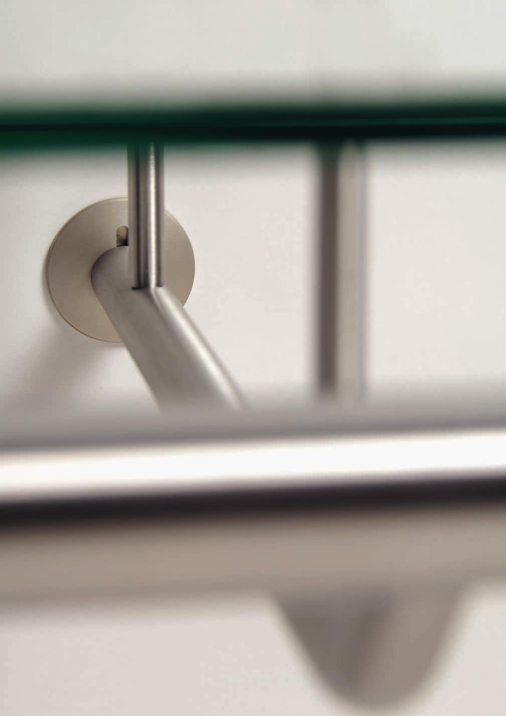
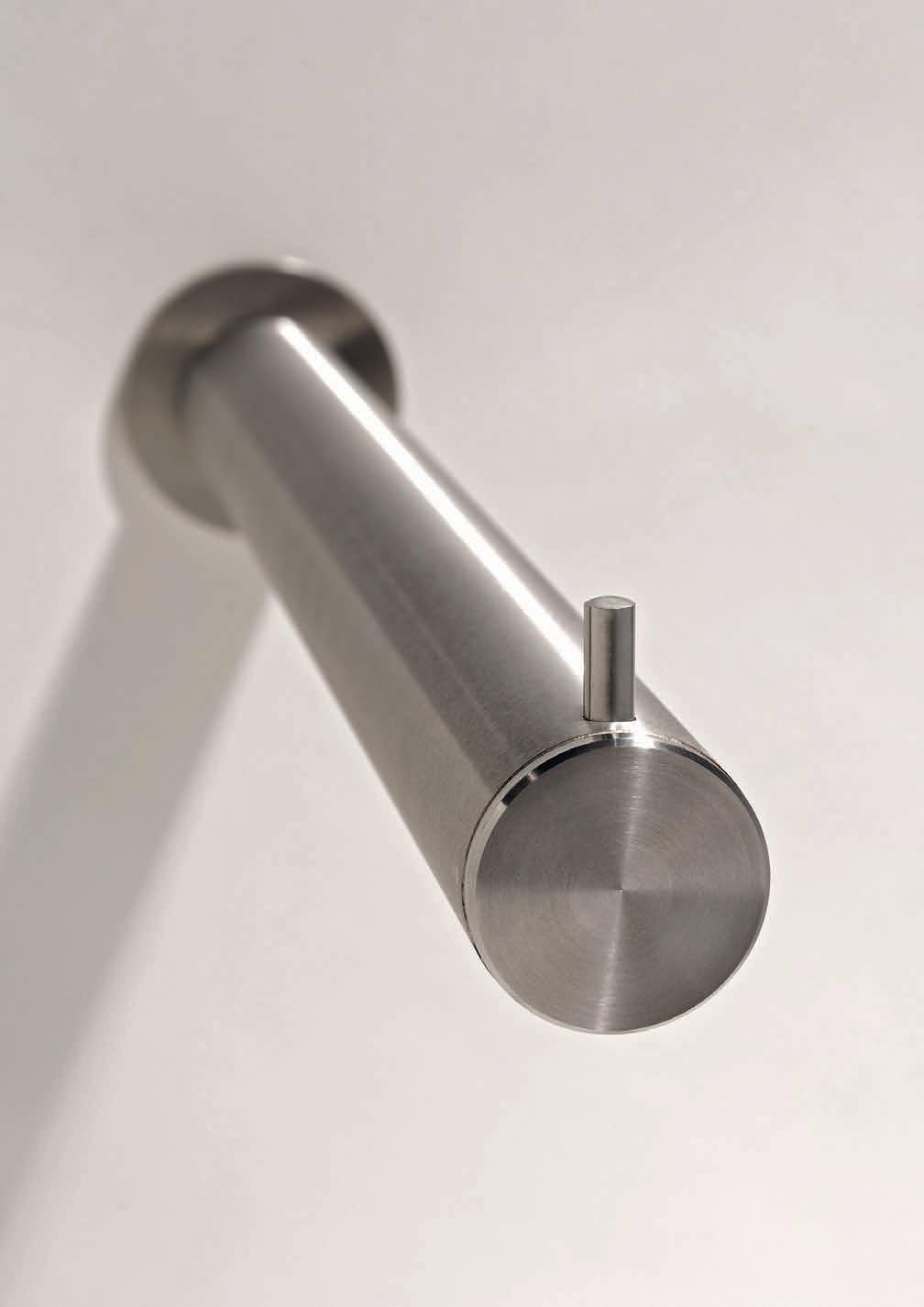
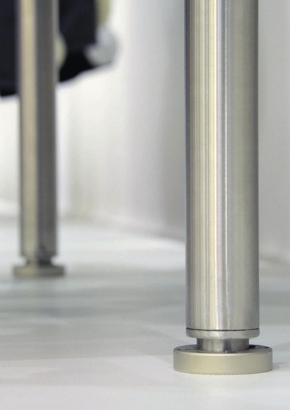
3 Perfoplug is a puck, or plug socket system that enables one to assemble all kinds of wall presentations. You can decide where to attach it, which quantity is desired, and which bolt pattern to use. We have set the standard at a 600 mm axis distance between centres of each presentation. There are six groups of products within the overall Perfoplug program. Our first program consists of matt nickel aluminum plug sockets that assume a conical shape towards the back side. The Ø15 mm rounded-off pins are elegant and refined. These are often used in shoe shops, fashion, lingerie and accessories, but also by private projects. Has the same technique as Perfoplug Base but comes in a more luxurious and robust design. The plug sockets are made of brushed stainless steel with compatible solid Ø20 mm or Ø30 mm brushed stainless steel tube. Perfoplug Premium can carry a heavier load and has a luxurious appearance. As the name implies, this is the light version of the Base program. The insert parts have a diameter of 12 mm. Perfoplug Lite is widely used in the lingerie sector. This program within the Perfoplug family contains two sub groups of diameters, Ø4 and Ø8 mm. The looks of this slim system makes Perfoplug Fine perfect for presenting lightweight products. In this program floor sockets are available with solid Ø15 mm tube, but there is also a heavier version where Ø25 mm or Ø30 mm tubes are available. This is a very stable system and fits perfectly onto the adapter. These series are especially fit for developing customized products. SPECIAL FEATURES: The plug sockets do not twist due to the sharp serrated edges at the back. A relatively large part of the plugs is in contact with the back wall. In comparison with other systems it is therefore stronger and can carry a heavier maximum load (the wood stays intact for a longer time). The Perfoplug system has many assembly possibilities. Not only assembly on standard plates but also on stone, concrete, glass, etc. Many similar systems start to sag under normal load, but the Perfoplug pins are bend slightly upwards because the pins are produced with an angle at the pin s end. The different pieces fit perfectly because the section of the pin inserted in the wall is conical. Furthermore, we have a hugely diverse range of insertable parts. Many different lengths are available as well. We even supply several adaptors that allow you to make customized insertable parts. Next to the plug sockets and the tubes, this documentation also contains the different assembly pieces, and instructions are available per assembly. Most pieces show maximum load. Calculations have been made to ensure minimal sag under maximum load. During this calculation we have only taken the maximum load of the sockets into account, not the load of the wooden panels. The quality of the base material the sockets are inserted in defines whether the maximum load can be safely achieved or not. We advise against the use of chipboard, please use MDF or birch plywood. General note:: This documentation has been produced with the utmost care. The information is non-binding and we accept no responsibility for its correctness. We are not liable for print or layout errors. In the interest of development, details are subject to change without prior notice.

 is applied to the stainless steel product.")

4 NEW COLOURS For many years we have been successfull with the Perfoplug puck system. The stainless steel insert parts give stores a luxurious look. Yet sometimes we get the question whether this system is also available in other materials. This is now possible. That is, we can now colour the stainless steel insert parts into various metal colours such as copper, bronze, brass, gold and more. During a unique process, the stainless steel gets its new colour and a harder and smoother surface layer (which is even more solid than chrome) is applied to the stainless steel product. During this treatment, the structure of the stainless steel is not affected. So if it is polished, it remains polished and when it is brushed this appearance remains unchanged. A second possibility is to manufacture the insert parts of aluminum and anodise these. This, too, offers a wide range of colours to apply. Please pay attention to the fact that aluminum parts have lower load capacities than the stainless steel insert parts. This gives a % lower maximum load capacity. Both ways of colouring come with additional costs. This is highly dependent on the volume and dimensions of the desired Perfoplug products. Please do not hesitate to ask us about the many possibilities.
5 BASE
6 PERFOPLUG BASE Plug sockets page 1 Assembly instructions page 2-3 Assembly material page 4-6 Front arms, Glass holders page 7-10 Shoe presentations page 10 Miscellaneous page 11 Hanging brackets page Fitting room accessories page 14


7 1 PLUG SOCKET Conical plug socket with sharp serrated edging for firm positioning. Anodized Aluminum satin nickel-plated Load cap. Depth See assembly instructions Stainless Steel See assembly instructions Ø 35 Ø Ø PLUG SOCKET WITH POSITION RIDGES Conical plug socket. On the back side two position ridges have been added to allow use with CNC fraise. Also for fast and easy assembly. Anodized Aluminum satin nickel-plated Load cap. Depth See assembly instructions Ø 35 Ø SCREW SOCKET TO BE USED WITH WOOD Conical screw socket to be screwed and glued into wooden frame. For retrofitting in existing panels using a minimum construction depth of 45 mm. Minimum panel thickness at least 18 mm. Anodized Aluminum satin nickel-plated Load cap. Depth See assembly Ø instructions WALL PLUG SOCKET Conical plug socket to be mounted on wall. Includes plastic plug S20. Anodized Aluminum satin nickel-plated Load cap. Depth See assembly Ø instructions

, the maximum loads using the collar nut Ø60mm are 17 and")
, the maximum loads using the Ø60 mm collar nut are 20 and 24 kg respectively.")
8 2 ASSEMBLY INSTRUCTIONS PLUG SOCKET (MOUNTING ON PLATES) 1. Accurately drill a Ø16 mm hole when using the standard assembly set containing a nut and two rings. 2. Accurately drill a Ø 20.2 mm hole when using the Ø60 mm collar nut. 3. Tighten plug socket and align it vertically using assembly wrench. 4. Maximum load depends heavily on type of plate material. The loads mentioned below have been based on at least 18 mm thick plates. When using a good quality chipboard and the standard assembly set the maximum loads are 15 and 16 kg (Ø35 and Ø40 mm plug socket respectively), the maximum loads using the collar nut Ø60mm are 17 and 19 kg respectively. However, we recommend the use of MDF or plywood, since these materials have proved to be a lot more stable. In this case the maximum loads using the standard assembly set are 17 and 19 kg (Ø35 and Ø40 mm plug socket), the maximum loads using the Ø60 mm collar nut are 20 and 24 kg respectively. To prevent the panel from bending it is advisable to attach vertical profiles lengthwise. ASSEMBLY INSTRUCTIONS PLUG SOCKET (MOUNTING ON GLASS) 1. Accurately drill (or have drilled) a hole of Ø22 mm. 2. Place the first glass ring over the plug socket, insert in hole and place second ring. 3. Tighten decorative nut with hook wrench ( ). Glass thickness may vary between 8-15 mm. 4. Use the assembly wrench to vertically align the plug socket. 5. The maximum load of the plug socket using glass depends entirely of the maximum load the glass can carry. For more information contact your glass supplier. ø 16mm 24mm mm depth: 5mm ASSEMBLY INSTRUCTIONS PLUG SOCKET WITH POSITION RIDGES 1. Hole size is Ø16 mm through-and-through. 2. The size of the two notches for the position ridges is Ø5 mm, the notches are 5 mm deep. 3. Attention: the position ridges should be located in a horizontal line to the hole, so at square angles with the vertically positioned notches on the front side of the plug socket. 4. The total distance between the ends of the notches should be 24 mm with a mm margin. 5. Also see diagram inlay in picture. 6. Maximum load depends heavily on type of plate material. The loads mentioned below have been based on at least 18 mm thick plates. When using a good quality chipboard and the standard assembly set the maximum loads are 15 and 16 kg (Ø35 and Ø40 mm plug socket respectively). However, we recommend the use of MDF or plywood, these materials have proved to be a lot more stable. In this case the maximum loads using the standard assembly set are 17 and 19 kg (Ø35 and Ø40 mm plug socket), the maximum loads using the Ø60 mm collar nut are 20 and 24 kg respectively. To prevent the panel from bending it is advisable to attach vertical profiles lengthwise.
, to the glue grooves of the mounting flange and in the hole in the panel. 4. Insert the flange into the hole and tighten onto panel using plywood screws Ø3 x 18 mm.")

. 1. Accurately drill a Ø15 mm hole. 2. Clean out hole by blowing and degrease plug socket. 3.")
9 3 ASSEMBLY INSTRUCTIONS MOUNTING FLANGE 1. Accurately drill a Ø20.2 mm hole. 2. Clean out hole by blowing and degrease mounting flange. 3. Apply glue, Araldite 2012 (setting time is 4 minutes), to the glue grooves of the mounting flange and in the hole in the panel. 4. Insert the flange into the hole and tighten onto panel using plywood screws Ø3 x 18 mm. 5. Insert the plug socket Ø35 mm into the flange and fasten. 6. Align the plug socket vertically using the assembly wrench. When needed use spacer ring(s) to align. 7. Attention: The use of chipboard is not advisable here, as maximum load is only 8 kg per plug socket. MDF, solid wood or plywood can take a considerably larger load, depending on material used and thickness, the maximum load lies between 14 and 18 kg. ASSEMBLY INSTRUCTIONS PLUG SOCKET (WOOD, PLATE AND SOLID WOOD). 1. Accurately drill a Ø15 mm hole. 2. Clean out hole by blowing and degrease plug socket. 3. Apply glue, Araldite 2012 (setting time is 4 minutes), to the glue grooves of the plug socket. 4. Insert the assembly wrench into the plug socket and using a hammer tap the plug socket until the thread in the hole. 5. Tighten plug socket with assembly wrench until the shoulder touches the wood and align the plug socket vertically. 6. Attention: The use of chipboard is not advisable here, as the maximum load is only 8 kg per plug socket. MDF, solid wood or plywood can take a considerably larger load, depending on material used and thickness the maximum load lies between 14 and 18 kg. ASSEMBLY INSTRUCTIONS WALL PLUG SOCKET 1. Make sure the letters TOP on the drilling jig point upwards. 2. Accurately drill a Ø20 mm hole with a minimum depth of mm. (Attention: minimum drill bit length 25 cm) 3. Push the plastic plug into the hole. When performing masonry push the plug in 15 mm, in the case of concrete push it in 25 mm. 4. Fasten the wall plug socket using the assembly wrench into the plastic plug until the shoulder hits the wall, and align the plug socket vertically. 5. The maximum load in this case is highly dependent on the state and the type of wall.


10 4 ASSEMBLY SET Assembly set for plug socket. Consists of a Ø70 mm counter disk, serrated ring and M16x1 nut. Maximum plate thickness 19 mm. Zinc-coated Steel Load cap. See assembly Ø instructions COLLAR NUT For heavy duty assembly with plug socket. With two 4.3 mm screw holes. Plate thickness 18 or 22 mm. The collar nut can not be used in combination with the plug socket with position ridges! Use cotter wrench to tighten ( ). Raw Aluminum Load cap. Depth See assembly instructions Ø 60 Ø SET OF GLASS RINGS To be used in assembly of plug socket on glass, sold in pairs. Clear Plastic Ø DECORATIONAL NUT FOR GLASS Nicely finished nut for assembly of plug socket onto glass (minimum 6 to maximum 16 mm) To attach, use hook wrench with pin ( ). Anodized Aluminum satin nickel-plated Load cap. Depth See assembly Ø instructions


11 5 SPACER RING To be used in combination with mounting flange, in order to be able to align the plug socket. Raw Aluminum Depth Ø MOUNTING FLANGE It is possible to use this assembly without attaching it to the back side. To be fastened on the front side, after which the plug socket can be inserted. Minimum depth 30 mm. Minimum wall thickness 18 mm. Raw Aluminum Load cap. Depth See assembly Ø instructions DRILLING JIG Drilling jig for wall plug socket, to make a hole in the right angle. With alignment grooves and TOP indication. Stainless Steel ASSEMBLY WRENCH Used to vertically align plug socket. Used for all sockets of the Base and Premium series except plug socket with position ridges. Stainless Steel

12 6 COTTER WRENCH Wrench for collar nut fastening HOOK WRENCH WITH PIN Wrench for fastening of decorational nut for glass shelf STAINLESS STEEL CLEANER & POLISH Cleans, shines and protects stainless steel in one application. Volume 600 ml
13 7 FRONT ARM WITH CAP Straight pin with conically shaped end cap. Load cap. Length FRONT ARM WITH STIFT Straight pin with stift Ø5 mm at the end. Load cap. Length CARRYING ARM FOR GLASS WITH CAP Straight pin with conical end cap and rubber glass rings at front and back for glass shelf. Load cap. Length CARRYING ARM FOR GLASS Straight pin with rubber glass rings at front and back for glass shelf. Load cap. Length
 and glued in wooden shelf. Shelf must be at least 38 mm thick. Drill diameter Ø15.2 mm.")

14 8 CARRYING ARM FOR WOOD Straight pin with two sunk-in holes Ø4 mm. For wooden shelf. Load cap. Length CARRYING ARM FOR BLIND ASSEMBLY Straight pin to be fully inserted (long bore) and glued in wooden shelf. Shelf must be at least 38 mm thick. Drill diameter Ø15.2 mm. Note: allways use pairwise. Load cap. Length PRESENTATION PIN Straight pin converted at the end by 20. Load cap. Length Ø 8 Ø 8 Ø 8 Ø PRESENTATION PIN WITH STIFT Straight pin with a stift at the end. Load cap. Length Ø 8 Ø 8 Ø 8 Ø


15 9 TIE PRESENTATION ARM Diagonal pin for 18 ties. Load cap. Length FRONT ARM SLOPING Diagonal pin with 7 or 8 studs for clothes hangers. Load cap. Length FRONT ARM STEPPED Stepped pin with conical cap at the end. Load cap. Height Depth HAT/HELMET HOLDER Holder with plastic top. Load cap. 14 Ø 12 Height 225 Depth


16 10 GLASS HOLDER Glass support for 8 mm glass shelf. Minimal two needed per shelf. Anodized Aluminum satin nickel-plated Load cap. Depth 9 Ø MONO GLASS HOLDER Single glass shelf holder for 6/8 mm glass with plastic clamp screws. Does not tilt. Anodized Aluminum satin nickel-plated Load cap. Depth 4 Ø SHOE RACK 600 Consists of two diagonal pins (bolt pattern 600 mm) and three crossbeams which can be adjusted in different positions. Load cap. Width Depth SHOE BRACKET To present one shoe. Load cap. 3 Ø 6 Width 185 Depth

. Stainless Steel 72.2246.")


17 11 WOOD ADAPTER For a small wooden shelf or acrylic shelf. Minimum thickness of wood is 16 mm and acrylic 12 mm and up. Drill a hole of Ø5 mm x 32 mm. Adapter with wood thread for bonding (two components glue). Stainless Steel SIGN HOLDER Holder for 4 mm thick advertisement sign. The sign can be attached at the back with two M4 screws. Anodized Aluminum satin nickel-plated Load cap. Depth 2 Ø PANEL HOLDER Holder with two holes Ø3.8 mm to attach panels or similar. Axis size of the holes is 22 mm. Use spax screws Ø3.5 mm. Raw Aluminum Depth Ø ADAPTER For various applications. To be used as base for customized presentation arms. Length


18 12 CARRIER ARM FOR HANGING BRACKET Carrier arm to be used with transverse carrier tube. Load cap. Depth CARRIER ARM FOR HANGING BRACKET WITH SHELF SUPPORT Carrier arm to be used with transverse carrier tube. Has two pins with a hole for protective support as well as thread M4 to attach thoroughly. Designed to support wooden or glass shelf. Load cap. Height Depth SHELF SUPPORT FOR HANGING BRACKET For a fixed attachment of a shelf onto the carrier arm for hanging bracket with shelf support. Allways make use of this support when using oversized shelfs. Including screws and protective glass supports. Height Width Depth ASSEMBLY INSTRUCTIONS HANGING BRACKET Turn the carrier arms into the holes of the carrier tube and attach the construction to the plug sockets. PROPERTIES The carrier arms points upwards at the ends. Because of this, the clothes hangers, as opposed to most other socket systems, can be moved along the whole length of the carrier tube. The separate delivery of the carrier arms and the carrier tube saves space during transport and storage. Furthermore, one can increase the maximum load by using more carrier arms. The length of the carrier tube can be adapted to the customer s needs on demand. It is also possible to order other carrier arms later on when one decides to use the version with the pins to support a shelf, or want to change the other way around, from shelf-carrier arms to regular ones.

 and amount of holes at client s choice. Width Ø 25.. 72.2122.")


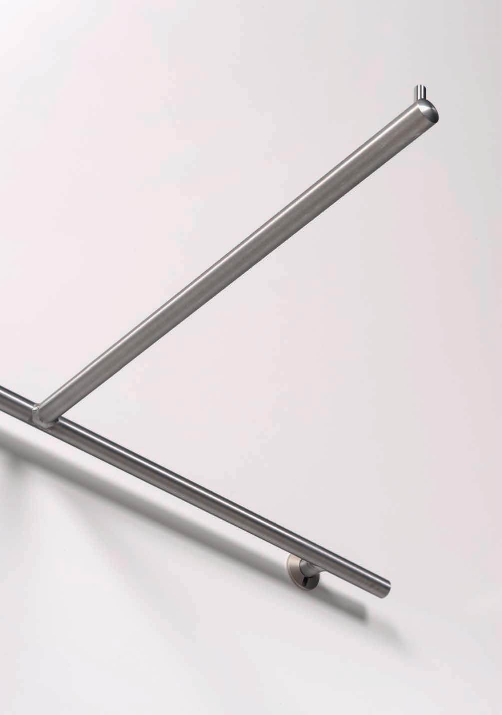
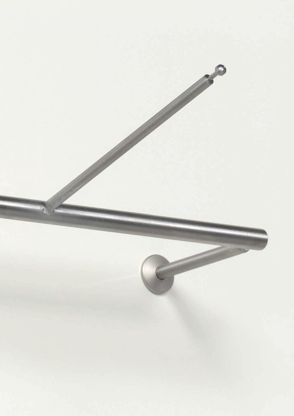
19 13 CARRIER TUBE FOR HANGING BRACKET Transverse carrier tube for hanging bracket with Ø35 mm end disc. Has three flow drilled holes, axis size 300 mm. Width Ø CARRIER TUBE FOR HANGING BRACKET Transverse carrier tube for hanging bracket with Ø35 mm end disc. Sizing (length) and amount of holes at client s choice. Width Ø T-ARM T-shaped arm with extra support for higher load and to prevent twisting. A second plug socket is needed here at a vertical axis distance of 200 mm. The carrier tube has a diameter of Ø20 mm with a Ø30 mm end disc. The arm points upwards at the end so the clothes hangers can slide all the way through. Load cap. Width Depth TUBE HOLDER Ø25 For mounting a tube Ø25 mm under a wooden shelf. With four screw holes Ø4.3 mm axis 21.5 mm. Height Depth Ø 10 / Ø


20 14 FLANGE STAINLESS STEEL Wall flange out of massive stainless steel including three sunk-in holes. Stainless Steel Depth Ø 60 / Ø FITTING ROOM CURTAIN ROD Rod Ø20 mm for fitting room curtain. Including assembly parts for blind assembling. Length is intermediate size. Length Ø FITTING ROOM HOOK Hook for fitting room. For bonding into wooden panels. Minimum wall thickness is 19 mm. Please note: only for light load. Length Ø 12 / FITTING ROOM HOOK Screw hook for fitting rooms with disc Ø20mm. Includes bolt M6 x 35 mm and a washer. Suitable for panels with a thickness of 16 to 22mm. Length Ø 12 /
21 PREMIUM
22 PERFOPLUG PREMIUM Plug sockets page 15 Assembly material page Assembly instruction page 16 Front arms page 17 Glass holders page 18 Shelf arms page Hanging brackets page Support bar, accessories page 21-22


23 15 PLUG SOCKET Luxurious flat plug socket with sharp serrated edging to ensure fixed position. Load cap. Depth See assembly Ø instructions COVERING CAP To cover the opening in unused plug sockets. Stainless Steel ASSEMBLY SET Assembly set for plug socket. Consists of a Ø70 mm counter disk, serrated ring and M16x1 nut. Maximum plate thickness 19 mm. Zinc-coated Steel Load cap. See assembly Ø instructions COLLAR NUT For heavy duty assembly with plug socket. With two 4.3 mm screw holes. Plate thickness 18 or 22 mm. Use cotter wrench to tighten ( ). Raw Aluminum Load cap. Depth See assembly instructions Ø 60 Ø

24 16 ASSEMBLY INSTRUCTIONS PLUG SOCKET 1. Accurately drill a Ø16 mm hole when using the standard assembly set (consists of one bolt and two rings) 2. Accurately drill a Ø20.2 mm hole when using the Ø60 mm collar nut. 3. Fasten the plug socket and align it vertically using the assembly wrench. 4. Maximum load depends heavily on type of plate material. Using a good quality chipboard and the standard attachment set, the maximum load is 20 kg; using the Ø60 mm collar nut it is 27 kg. However, we recommend the use of MDF or plywood, these materials have proved to be a lot more stable. In this case the maximum load using the standard assembly set is 26 kg, the maximum load using the Ø60 mm collar nut is 35 kg. To prevent the panel from bending it is advisable to attach vertical profiles lengthwise. ASSEMBLY WRENCH Used to align the plug socket vertically. Stainless Steel COTTER WRENCH Wrench for collar nut fastening
25 17 FRONT ARM 100 Straight pin with a Ø5 mm stift at the end. Load cap. Length 35 Ø FRONT ARM 200 Straight pin with a Ø5 mm stift at the end. Load cap. Length 30 Ø FRONT ARM 300 Straight pin with a Ø5 mm stift at the end. Load cap. Length 27 Ø FRONT ARM 400 Straight pin with a Ø5 mm stift at the end. Load cap. Length 23 Ø
26 18 CARRYING ARM FOR GLASS 200 Straight pin with two protective supports for glass. For glass shelf. Load cap. Length 25 Ø CARRYING ARM FOR GLASS 300 Straight pin with two protective supports for glass. For glass shelf. Load cap. Length 22 Ø CARRYING ARM FOR GLASS 400 Straight pin with two protective supports for glass. For glass shelf. Load cap. Length 18 Ø CARRYING ARM FOR WOOD 200 Straight pin with two sunk-in holes Ø5.2 mm. For wooden shelf. Load cap. Length 32 Ø


27 19 CARRYING ARM FOR WOOD 300 Straight pin with two sunk-in holes Ø5.2 mm. For wooden shelf. Load cap. Length 30 Ø CARRYING ARM FOR WOOD 400 Straight pin with two sunk-in holes Ø5.2 mm. For wooden shelf. Load cap. Length 25 Ø FRONT ARM SLOPING Diagonal pin with seven Ø5 mm studs for clothes hangers. Load cap. Depth 25 Ø FRONT ARM STEPPED Stepped pin with Ø8 mm studs at the end. Load cap. Height 25 Ø Depth


28 20 CARRIER ARM FOR HANGING BRACKET Carrier arm to be used with transverse carrier tube. Load cap. Depth 30 Ø CARRIER ARM FOR HANGING BRACKET WITH SHELF SUPPORT Carrier arm to be used with transverse carrier tube. Has two pins with a hole for protective support as well as thread M4 to attach thoroughly. Designed to support wooden or glass shelf. Load cap. 30 Ø 20 Height 100 Depth ASSEMBLY INSTRUCTIONS HANGING BRACKET Turn the carrier arms into the holes of the carrier tube and attach the construction to the plug sockets. PROPERTIES The carrier arms point upwards at the ends. Because of this, the clothes hangers, as opposed to most other socket systems, can be moved along the whole length of the carrier tube. The separate delivery of the carrier arms and the carrier tube saves space during transport and storage. Furthermore, one can increase the maximum load by using more carrier arms. The length of the carrier tube can be adapted to the customer s needs on demand. It is also possible to order other carrier arms later on when one decides to use the version with the pins to support a shelf, or want to change the other way around, from shelf-carrier arms to regular ones. CARRIER TUBE FOR HANGING BRACKET Transverse carrier tube for hanging bracket with Ø5 mm stifts at each end. Sizing (length) and the amount of holes at client s choice. Width Ø


29 21 CARRIER TUBE FOR HANGING BRACKET 1160 Transverse carrier tube for hanging bracket with Ø5 mm stifts at each end. Has three flow drilled holes, axis 300 mm. Width Ø CARRIER ARMS FOR SUPPORT BAR Carrier arms for support bar. Sold in pairs. Load cap. Depth 25 Ø STRIP FOR SUPPORT BAR Luxury support bar made of flat brushed stainless steel strip. All kinds of pins can be hooked onto it, axis 600 mm. To be used with carrier arms. Height Width Depth PRESENTATION HOOK Straight pin for support bar converted at the end by 20. Load cap. Length Ø 6 Ø 6 Ø


30 22 FRONT ARM SUPPORT BAR Straight pin for support bar with end-notch. Load cap. Length 7 7 Ø 20 Ø FRONT ARM SLOPING FOR SUPPORT BAR Diagonal pin for support bar with 6 notches for clothes hangers. Load cap. Depth 7 Ø CARRIER ARM FOR HANGING BAR Carrier arms for hanging bar. Sold in pairs. To be used with strip. Load cap. Depth Ø 20 Ø STRIP FOR HANGING BAR Luxury hanging bar made of brushed stainless strip, using transparent plastic top profile for protection of hangers, pitch 600 mm. To be used with carrier arms. Height Width Depth
31 LITE
32 PERFOPLUG LITE Plug sockets page 23 Assembly materials page Assembly instructions page 24 Front arms page 25 Carrier arms glass page 26 Carrier arms wood page 26 Front arm sloping page 26 Hanging brackets page 27-28


33 23 PLUG SOCKET LITE Conical plug socket with sharp serrated edging for firm positioning. Anodized Aluminum satin nickel-plated Load cap. Depth See assembly Ø instructions Stainless Steel See assembly Ø instructions PLUG SOCKET LITE WITH POSITION RIDGES Conical plug socket. On the back side two position ridges have been added to allow use with CNC fraise. Also for fast and easy assembly. Anodized Aluminum satin nickel-plated Load cap. Depth See assembly Ø instructions ASSEMBLY SET Assembly set for plug socket. Consists of a Ø50 mm counter disk, serrated ring and M16x1 nut. Maximum plate thickness 19 mm. Zinc-coated Steel Load cap. See assembly Ø instructions COLLAR NUT For heavy duty assembly with plug socket. With two 4.3 mm screw holes. Plate thickness 18 or 22 mm. Use cotter wrench to tighten ( ). Raw Aluminum Load cap. Depth See assembly instructions Ø 60 Ø

 1. Accurately drill a Ø20.")

34 24 ASSEMBLY INSTRUCTIONS PLUG SOCKET (MOUNTING ON PLATES USING THE STANDARD ASSEMBLY SET) 1. Accurately drill a Ø16 mm hole. 2. Tighten plug socket and align it vertically using assembly wrench. 3. Maximum load depends heavily on type of plate material. The loads mentioned below have been based on at least 18 mm thick plates. When using a good quality chipboard the maximum load is 10 kg. However, we recommend the use of MDF or plywood, these materials have proved to be a lot more stable. In this case the maximum load is 12 kg. To prevent the panel from bending it is advisable to attach vertical profiles lengthwise. ASSEMBLY INSTRUCTIONS PLUG SOCKET (MOUNTING ON PLATES USING THE Ø60 MM COLAR NUT) 1. Accurately drill a Ø20.2 mm hole. 2. Tighten plug socket and align it vertically using assembly wrench. 3. Maximum load depends heavily on type of plate material. The loads mentioned below have been based on at least 18 mm thick plates. When using a good quality chipboard the maximum load is 13 kg. However, we recommend the use of MDF or plywood, these materials have proved to be a lot more stable. In this case the maximum load is 15 kg. To prevent the panel from bending it is advisable to attach vertical profiles lengthwise. ø 16mm 5mm depth: 5mm 24mm +0.1 ASSEMBLY INSTRUCTIONS PLUG SOCKET WITH POSITION RIDGES 1. Hole size is Ø16 mm through-and-through and the size of the two notches for the position ridges is Ø5 mm, the notches are 5 mm deep. (Attention: the position ridges should be located in a horizontal line to the hole, so at square angles of the vertically positioned notches on the front side of the plug socket.) 2. The total distance between the ends of the notches should be 24 mm with a mm margin. (Also see diagram inlay in picture.) 3. Maximum load depends heavily on type of plate material. The loads mentioned below have been based on at least 18 mm thick plates. When using a good quality chipboard and the standard assembly set the maximum load is 10 kg. However, we recommend the use of MDF or plywood, these materials have proved to be a lot more stable. In this case the maximum load using the standard assembly set is 12 kg. To prevent the panel from bending it is advisable to attach vertical profiles lengthwise.


35 25 ASSEMBLY WRENCH Used to vertically align plug socket. Used for all plug sockets except plug sockets with position ridges. Stainless Steel COTTER WRENCH Wrench for collar nut fastening FRONT ARM Ø12 WITH STIFT Straight pin with stift Ø5 mm at the end. Load cap. Length Ø 12 Ø 12 Ø 12 Ø T FRONT ARM Ø12 WITH STIFT Horizontal bracket between two plug sockets with straight pin Ø12 mm and with stift Ø5 mm at the end. Axis of the plug sockets is 400 mm. Load cap. Width Length 15 Ø


36 26 CARRIER ARM FOR GLASS Straight pin with rubber glass rings at front and back for glass shelf. Load cap. Length Ø 12 Ø 12 Ø CARRIER ARM FOR WOOD Straight pin with two sunk-in holes Ø4 mm. For wooden shelf. Load cap. Length Ø 12 Ø FRONT ARM SLOPING Diagonal pin with 7 stifts for clothes hangers. Load cap. Length 11 Ø
 and the amount of holes at client s choice. Length.")


37 27 CARRIER ARM FOR HANGING BRACKET Carrier arm to be used with transverse carrier tube. Load cap. Length 10 Ø CARRIER TUBE FOR HANGING BRACKET Transverse carrier tube for hanging bracket with Ø5 mm stifts at each end. Sizing (length) and the amount of holes at client s choice. Length CARRIER TUBE FOR HANGING BRACKET 1160 Transverse carrier tube for hanging bracket with Ø5 mm stifts at each end. With two drilled holes, axis 400 mm. Length ASSEMBLY INSTRUCTIONS HANGING BRACKET: Put the carrier arms into the holes of the carrier tube and attach the construction to the plug sockets. PROPERTIES: The carrier arms point upwards at the ends. Because of this, the clothes hangers, as opposed to most other socket systems, can be moved along the whole length of the carrier tube. The separate delivery of the carrier arms and the carrier tube saves space during transport and storage. Furthermore, one can increase the maximum load by using more carrier arms. The length of the carrier tube can be adapted to the customer s needs on demand.
38 28
39 FINE
40 PERFOPLUG FINE Plug sockets Ø4 page 29 Assembly instructions Ø4 page 30 Assembly material Ø4 page 31 Presentation pins Ø4 page 31 Shoe bracket Ø4 page 31 Glasses presentations Ø4 page 32 Plug sockets Ø8 page 33 Assembly instructions Ø8 page 34 Assembly material Ø8 page 35 Front arms Ø8 page 36 Shelf arms Ø8 page 36 Slanted arm Ø8 page 36 Shoe bracket Ø8 page 37 Glasses presentation Ø8 page 37 Accessories Ø8 page 37-38


41 29 PLUG SOCKET Ø4 Conical plug socket including assembly set (nut and disk). Fit for accessories with a diameter of Ø4 mm. Anodized Aluminum satin nickel-plated Load cap. See assembly instructions Ø 14.5 Length PLUG SOCKET Ø4 SPECTACLE Same as above, only this plug socket is especially made for the MONO glasses holder. Anodized Aluminum satin nickel-plated Load cap. See assembly instructions Ø 14.5 Length BRIL PLUG SOCKET Ø4 FOR BONDING Conical plug socket for bonding into wood. Minimum wall thickness is 16 mm. Fit for accessories with a diameter of Ø4 mm. Anodized Aluminum satin nickel-plated Load cap. See assembly instructions Ø 14.5 Depth WALL PLUG SOCKET Ø4 Conical plug socket to be mounted on wall. Includes plastic plug. Fit for accessories with a diameter of Ø4 mm. Anodized Aluminum satin nickel-plated Ø 14.5 Depth


42 30 ASSEMBLY INSTRUCTIONS PLUG SOCKET (MOUNTING ON PLATES) 1. Accurately drill a Ø8 mm hole and place the plug socket. 2. To tighten the nut, use a wrench no To align the plug socket vertically, use a hexagon wrench no Load capacity: only for lightweight products such as accessories and glasses. ASSEMBLY INSTRUCTIONS PLUG SOCKET (MOUNTING ON GLASS) 1. Accurately drill (or have drilled) a Ø10 mm hole. 2. Place the first glass ring over the plug socket, insert in hole and place second ring. 3. Tighten the nut. Glass thickness may vary between 6 and 15 mm. 4. To align the plug socket vertically, use a hexagon wrench no Load capacity: only for lightweight products such as accessories and glasses. ASSEMBLY INSTRUCTIONS PLUG SOCKET FOR BONDING 1. Accurately drill a Ø8 mm hole. 2. Clean out the hole by blowing and degrease plug socket. 3. Aply glue, Araldite 2012, to the glue grooves of the plug socket. 4. Insert the plug socket with rotating motion into the wood. 5. To align the plug socket vertically, use a hexagon wrench no Load capacity: only for lightweight products such as accessories and glasses. ASSEMBLY INSTRUCTIONS WALL PLUG SOCKET 1. Accurately drill a Ø10 mm hole with a depth of 37 mm minimum. 2. Clean out the hole by blowing. 3. Insert the included plastic plug into the hole. 4. Tighten and align the plug socket wall vertically, into the plastic plug, using a hexagon wrench no Load capacity: only for lightweight products such as accessories and glasses.

.")


43 31 SET OF GLASS RINGS To be used in assembly of plug socket on glass, sold in pairs. Clear Plastic Ø DECORATIONAL NUT FOR GLASS Nicely finished nut for assembly of plug socket onto glass (minimum 6 to maximum 16 mm). Raw Aluminum Depth PRESENTATION PIN Ø4 Presentation pin converted at the end by 20. For load, see assembly instructions. Ø 4 Ø 4 Ø 4 Length SHOE BRACKET Ø4 Single shoe presentation. Axis size is 190 mm. Stainless Steel Ø 4 Width 194 Depth

 Ø 4 Width 180 Depth 165 72.5460.")


44 32 MONO GLASSES HOLDER Single spectacle presentation. IMPORTANT: use only in combination with the special plug socket Ø4 mm spectacle. ( BRIL) Ø 4 Width 180 Depth SOLO GLASSES HOLDER Single spectacle presentation. Axis size is 190 mm. Ø 4 Width 200 Depth DUO GLASSES HOLDER Dual spectacle presentation. Axis size is 380 mm. Ø 4 Width 390 Depth TRIO GLASSES HOLDER Triple spectacle presentation. Axis size is 570 mm. Ø 4 Width 580 Depth


45 33 PLUG SOCKET Ø8 Conical plug socket including plain nut Ø25 mm with two screw holes. Fit for accessories with a diameter of Ø8 mm. Anodized Aluminum satin nickel-plated Ø 22 Depth PLUG SOCKED Ø8 FOR BONDING Conical plug socket for bonding into wood. Minimum wall thickness is 16 mm. Fit for accessories with a diameter of Ø8 mm. Anodized Aluminum satin nickel-plated Ø 22 Depth WALL PLUG SOCKET Ø8 Conical plug socket to be mounted on wall. Includes plastic plug. Fit for accessories with a diameter of Ø8 mm. Anodized Aluminum satin nickel-plated Depth


46 34 ASSEMBLY INSTRUCTIONS PLUG SOCKET (MOUNTING ON PLATES) 1. Accurately drill a Ø12 mm hole and place the plug socket. 2. To tighten the plain nut, use hook wrench with pin ( ). For extra security, the use of two screws through the holes is possible. 3. To align the plug socket vertically, use a hexagon wrench no The maximum load is 3 kg per plug socket. ASSEMBLY INSTRUCTIONS PLUG SOCKET (MOUNTING ON GLASS) 1. Accurately drill (or have drilled) a Ø14 mm hole. 2. Place the first glass ring over the plug socket, insert in hole and place second ring. 3. Tighten the nut. Glass thickness may vary between 8 and 15 mm. 4. To align the plug socket vertically, use a hexagon wrench no The maximum load is 3 kg per plug socket. ASSEMBLY INSTRUCTIONS PLUG SOCKET FOR BONDING 1. Accurately drill a Ø12 mm hole. 2. Clean out the hole by blowing and degrease plug socket. 3. Aply glue, Araldite 2012, to the glue grooves of the plug socket. 4. Insert the plug socket with rotating motion into the wood. 5. To align the plug socket vertically, use a hexagon wrench no The maximum load is 2.5 kg per plug socket. ASSEMBLY INSTRUCTIONS WALL PLUG SOCKET 1. Accurately drill a Ø14 mm hole, with a minimum depth of mm, using the drilling jig. Make sure the word TOP on the drilling jig point upwards. 2. Clean out the hole by blowing. 3. Push the plastic plug into the hole. When performing masonry push the plug in 6 mm, in the case of concrete push it in 18 mm. 4. Tighten and align the wall plug socket vertically, into the plastic plug, using a hexagon wrench no The maximum load is 3.5 kg per plug socket.

.")

47 35 SET OF GLASS RINGS To be used in assembly of plug socket on glass, sold in pairs. Clear Plastic Ø DECORATIONAL NUT FOR GLASS Nicely finished nut for assembly of plug socket onto glass (minimum 6 to maximum 16 mm). Raw Aluminum Ø 25 Length DRILLING JIG Drilling jig for wall plug socket, to make a hole in the right angle. Has alignment grooves and TOP indication. Stainless Steel


48 36 FRONT ARM Straight pin with stift at end. Load cap Ø 8 Ø 8 Ø 8 Ø 8 Ø 8 Length PRESENTATION ARM Straight pin converted at the end by 20. Load cap Ø 8 Ø 8 Ø 8 Ø 8 Ø 8 Length CARRYING ARM GLASS/WOOD Staight pin with two rubber rings for lightweight glass- wooden shelf. Load cap Ø 8 Ø 8 Ø 8 Ø 8 Length FRONT ARM SLOPING Curved sloping pin with 7 studs. Load cap. 2.5 Ø 8 Length


49 37 SHOE ARM Straight pin to present shoes. Use pairwise per shoe. Load cap. 2.5 Ø 8 Length GLASS HOLDER FOR GLASSES Glass holder for 6 mm glass. Due to the distance of the glass of 33 mm from the wall, the legs of the spectacles can hang over the edge of the shelf. Use at least two holders a shelf. Adviced axis size is 190 mm per spectacle. Anodized Aluminum satin nickel-plated Load cap. 2.5 Ø 17.5 Length PANEL HOLDER Holder with two holes Ø3.5 mm to attach panels or similar. Axis size of the holes is 17 mm. Raw Aluminum Ø 25 Depth
50 38
51 FLOOR
52 PERFOPLUG FLOOR Duckboard plug sockets page 39 Assembly instructions page 39 Assembly material page Insertable parts for metal, wood and glass page Shoe holders page 42 Price card holders page 42 Floor sockets Ø60 and Ø40 page 43 Assembly material page 43 Assembly instructions page 44 Caps page 45 Adaptors page 45


53 39 DUCKBOARD PLUG SOCKET Plug socket to be attached to duckboard, with a sharp serrated edging for fixed positioning. Ø 40 Depth DUCKBOARD PLUG SOCKET SQUARE Plug socket to be attached to duckboard, with a sharp serrated edging for fixed positioning. Anodized Aluminum satin nickel-plated 40x40 Depth COLLAR NUT For assembly with duckboard plug socket. Has two 4,3 mm screw holes. Plate thickness 18 or 22 mm. Use cotter wrench to tighten ( ). Raw Aluminum Ø 60 Ø 60 Depth ASSEMBLY INSTRUCTIONS DUCKBOARD PLUG SOCKET 1. Accurately drill a Ø20.2 mm hole. 2. Place the Ø60 mm collar nut and the duckboard plug socket. 3. Align with the assembly wrench and tighten using the cotter wrench. ( )


54 40 ASSEMBLY WRENCH Use to align duckboard plug socket. Stainless Steel COTTER WRENCH Wrench for collar nut tightening FLOOR PIN Upright pin to make custom presentations. Height DECO PLATFORM Upright pin with horizontal platform. Height Width Depth


55 41 DECO PLATFORM SLOPING Upright pin with diagonal platform. Height Width Depth PLATFORM PIN Upright pin with horizontal flange with four mounting holes for a wooden platform. Height PLATFORM PIN SLOPING Upright pin with diagonal flange with four mounting holes for a wooden platform. Height FLOOR PIN FOR GLASS Upright pin to support horizontal glass surface. Hole in glass should be Ø12 mm. Includes plastic glass rings and socket head screw. Height


56 42 SHOE PRESENTER Upright pin with slanted platform to present a shoe. Height SIGN HOLDER STAND Upright pin with support for a sign holder. Available in several heights and widths on request. Comes without acrylic sign holder. Ø 12

 Floor socket for existing concrete floor.")


57 43 FLOOR SOCKET (FS Ø 60) Floor socket for wooden floor. Includes assembly parts. This is a very stable system that fits perfectly on the adapter. Compatible with plate thickness of mm. The standard thickness is 38 mm. Anodized Aluminum satin nickel-plated Ø 60 Depth FLOOR SOCKET (FS Ø 60) Floor socket for existing concrete floor. This is a very stable system that fits perfectly on the adapter. Anodized Aluminum satin nickel-plated Ø 60 Depth FLOOR SOCKET (FS Ø 40) Floor socket for wooden floor with sharp serrated edging for firm positioning. Includes Ø60 mm counter nut. This is a very stable system that fits perfectly on the adapter. Compatible with plate thickness of mm. Anodized Aluminum satin nickel-plated Ø 40 Depth HOOK WRENCH WITH PIN MM Wrench to attach counter nut of floor socket Ø


58 44 ASSEMBLY INSTRUCTIONS FLOOR SOCKET Ø 60 ON WOOD 1. Accurately drill a Ø35 mm hole straight into the wood. 2. Drill four Ø7 mm holes crossways outside of the inner hole with a axis of 50 mm. 3. Insert the floor socket in the hole and place the Ø80 mm washer ring. 4. Put the 4 socket head screws with their washers through the four holes onto the floor socket and tighten firmly. The bolts that are delivered are compatible with 38 mm thick plates. Other lengths are available on request. ASSEMBLY INSTRUCTIONS FLOOR SOCKET Ø 60 ON CONCRETE FLOOR 1. Accurately drill a Ø40 mm hole into the concrete that is 150 mm deep. 2. Clean the hole and clear all dust. 3. Inject chemical anchor in hole (Hilti HIT-HY 150) by pouring in a circle turning. 4. Insert the floor socket precisely in the middle of the hole while turning. Also see instruc-tion manual for chemical anchor. ASSEMBLY INSTRUCTIONS FLOOR SOCKET Ø 40 ON WOOD 1. Accurately drill a Ø28 mm straight hole into the wood. 2. Put floor socket through hole. 3. Tighten counter nut Ø60 mm using hook wrench with pin. ( )


59 45 COVER PLATE FS Ø 60 To cover the opening of unused floor socket Ø 60. Anodized Aluminum satin nickel-plated Ø COVER PLATE FS Ø 40 To cover the opening of unused floor socket Ø 40. Anodized Aluminum satin nickel-plated Ø ADAPTER FS Ø 60 Conical insertable adapter for Ø60 mm wood/concrete floor socket. Ø25x2 mm or Ø30x2 mm tubes can be shrunk/welded onto this adapter for custom applications. Stainless Steel Ø 20.5 Ø ADAPTER FS Ø 40 Conical insertable adapter for Ø40 mm wood floor socket. Ø25x2 mm or Ø30x2 mm tubes can be shrunk/welded onto this adapter for custom applications. Stainless Steel Ø 20.5 Ø
60 Perfotube b.v. P.O. Box 115 NL-3925 ZJ Scherpenzeel Visit address: Hooge Hoek 13a NL-3927 GG Renswoude The Netherlands +31 (0) (0)
Organisational Kitchen Fittings Kitchen Cabinet Accessories
 Kitchen waste bin systems Single waste bin, capacity 1 litres Carcase width: Min. 400 mm For door mounting: For left and right hand use Installation: Screw fixing to side panel Housing: Steel, plastic
Interior Equipment/Shop Fittings
 Interior Equipment/ Contents Room and Frontwall Systems DIFLEX Adjusting foot for raised floors Hook-in profile Hook-in profile Eilox SHOPTEC Shopfitting system Wall channel Bracket Column Accessories
aluminium profile system
 aluminium profile system 63 AME System aluminium profiles overview series profiles introduction 80x80 x80 x80/180 x Aluminium profiles are provided with longitudinal grooves which can be used in conjunction
Section 11 CABLE & ROD SYSTEMS, SIGN FIXING & SIGN STANDOFFS. Web. acrylicdesign.ie .
 Section 11 CABLE & ROD SYSTEMS, SIGN FIXING & SIGN STANDOFFS Web. acrylicdesign.ie Email. sales@acrylicdesign.ie Acrylic Design 2004-2015 Mobile Cable System Components Single panel clamp Stand Off for
Table and Furniture Base Fittings Plinth Adjusting Fittings
 Adjusting screw with M8 or M thread Rigid, for glide inserts, steel thread Finish/Colour: Black, thread galvanized Version: With acceptance Ø30 mm Thread M8 650.22.381 M 650.22.382 Packing: 1 or 0 pcs.
Connector Technology, Shelf Supports Connection Fittings
 MODULAR Connection fitting for recess mounting Finish: Burnished : For recess mounting The plate should allways be installed so that the supporting plate butts against the end of the recess. For rapid
Installation Instructions
 by Plato Woodwork Installation Instructions Plato Woodwork, Inc. 200 Third Street SW P.O. Box 98 Plato, MN 55370 www.platowoodwork.com 800.328.5924 SECTION GUIDE GETTING STARTED PAGE # Installation Methods...
MM340 Installation Instructions IMPORTANT SAFETY INSTRUCTIONS - SAVE THESE INSTRUCTIONS
 MM30 Installation Instructions IMPORTANT SAFETY INSTRUCTIONS - SAVE THESE INSTRUCTIONS Please read this entire manual before you begin. Do not unpack any contents until you verify all requirements on PAGE.
ELEGANCE SHOWER DOOR/ENCLOSURE INSTALLATION INSTRUCTIONS. Style A Style B Style C Style D
 ELEGANCE SHOWER DOOR/ENCLOSURE INSTALLATION INSTRUCTIONS IMPORTANT DreamLine reserves the right to alter, modify or redesign products at any time without prior notice. For the latest up-to-date technical
aluline 1 These aluboard8 rails are black anodised, as per customer s request.
 p. 8 aluline These aluboard8 rails are black anodised, as per customer s request. 2 The steel shelves are powder coated in black in order to match with the rails. 5 Of course, the mobile shop stands made
Ready To Go SimpleSpec tm. Installation Manual. For more information, please visit 3-form.com or call
 Contents Overview ( 1) 3/8" Varia Panel = Cable Tensioner with Cover Plate KIT Stainless Steel: 3-15-1636-K Black Oxide: 3-15-2005-K Cable Tensioner with Cover Plate SS: 3-15-1636 BO: 3-15-2005 + M8 Thread
MM540 Installation Instructions IMPORTANT SAFETY INSTRUCTIONS - SAVE THESE INSTRUCTIONS
 MM50 Installation Instructions IMPORTANT SAFETY INSTRUCTIONS - SAVE THESE INSTRUCTIONS Please read this entire manual before you begin. Do not unpack any contents until you verify all requirements on PAGE.
Interior Equipment, Shop Fittings
 Interior Equipment, Häfele, the brand you can trust. The innovator of functionality. Contents Room and Frontwall Systems DIFLEX Adjusting foot for raised floors Hook-in profile Eilox SHOPTEC Shopfitting
i-puc Merchandising & Display System Creative Display Solutions
 i-puc Creative Display Solutions i-puc Discreet in appearance and amazingly versatile in application, this cleverly engineered display program provides a distinctive innovation in puck based merchandising
Storage Cabinets 9000 Series Assembly Instructions
 Storage Cabinets 9000 Series Assembly Instructions Thank you for selecting Salsbury s storage cabinets. We are confident that the quality and construction of the cabinets will prove to be a good investment.
Leveling Feet, Base Plates and Casters
 Leveling Feet, Base Plates and Casters 77 Leveling Foot 1 1 Fastening to profile end Fastening in T-slot of profile For leveling tables and light equipment. Ratchet-type height adjustment requires no tools.
Adjustable Feet Castors Accessories for Floor Elements
 Adjustable Feet Castors Accessories for Floor Elements Products in this section Levelling Knuckle Feet Threaded spindles for infinite height adjustment Metal or plastic foot plate Knuckle Feet X Compatible
MM750 Installation Instructions
 MM750 Installation Instructions IMPORTANT SAFETY INSTRUCTIONS - SAVE THESE INSTRUCTIONS Please read this entire manual before you begin. Do not unpack any contents until you verify all requirements on
INSTALLATION GUIDE DUOFUSE SLAT WALL SYSTEM
 06/2013 ENG 1 INSTALLATION GUIDE DUOFUSE SLAT WALL SYSTEM The Duofuse wood composite slat wall system is much more durable than wooden fences, and correct installation is necessary to enjoy the fences
Wooden Frame Type Instruction Manual
 Wooden Frame TypeInstruction Manual Thank you for selecting our product. Before starting installation, please read this manual thoroughly to ensure correct installation. Please keep this manual at hand
Door Hinges Drill-in Hinges
 Drill-in hinge StarTec Frame part For timber lining frames For rebated doors Maintenance-free friction bearing To use in combination with receiver Max. door weight: 40 kg Knuckle: Ø15 mm Drilling bit Ø7.2
Aluminum Frame Type Instruction Manual
 Aluminum Frame TypeInstruction Manual Thank you for selecting our product. Before starting installation, please read this manual thoroughly to ensure correct installation. Please keep this manual at hand
Piazzola Pergola Awning Manufacturing and installation guide
 Piazzola Pergola Awning Manufacturing and installation guide Date Changes Page General information Maximum and minimum width Width Projection 150 to 349 cm 350 to 500 cm From 200 to 250 cm X From 251 to
FURNITURE HARDWARE & ACCESSORIES - PART 2 : SHELF SUPPORT AND SHELVING SYSTEMS
 www.hafeleindia.com FURNITURE HARDWARE & ACCESSORIES - PART 2 : SHELF SUPPORT AND SHELVING SYSTEMS ABOUT ITALIANA FERRAMENTA ITALIANA FERRAMENTA is specialized in the production of high quality accessories
SAM. Model: STV-C65 LCD Mobile Visualized Stand Instruction Manual. Weight Capacity: 1251bs / 56.7kg Suits LCD Flat Panel Display: 42"-55" Page 20
 SAM Model: STV-C65 LCD Mobile Visualized Stand Instruction Manual Weight Capacity: 1251bs / 56.7kg Suits LCD Flat Panel Display: 42"-55" 20 Step 6 LCD Mobile Lift Stand Model: STV-C65 Cable management
Greenhouse Assembly Instructions
 Greenhouse Assembly Instructions Our Help Line provides support and advice to customers of Summer Garden Buildings after ordering. For advice before you buy you can phone us free 7 days a week on 0800
OPERATIONS MANUAL. Port-O-Slitter
 Tapco Products Company The World Leader in Specialty Tools for the Professional Port-O-Slitter OPERATIONS MANUAL General instructions, set up, accessories and guide to using your portable precision slitting,
Equilibrium. Conference Table. Installation Instruction. Revision B 11/07/16
 Equilibrium Conference Table Installation Instruction Revision B 11/07/16 Equilibrium End User Agreement Enwork Equilibrium table bases must be installed directly onto a four inch minimum thickness concrete
Installation Instruction
 Tools Needed for Assembly Stud finder (for wood stud wall) Pencil Mark Electric drill Wood Stud Wall Installation Step 1. Locate the Wood Studs Installation Instruction Drill bit (for wood stud wall) Masonry
GROWING BETTER THROUGH DESIGN. 6ft Lean-To LEAN-TO. Assembly Instructions 04/02
 GROWING BETTER THROUGH DESIGN 6ft Lean-To LEAN-TO Assembly Instructions 04/02 6ft Lean-To Greenhouse Base Plan Introduction/Tools/Contents / / Contents This is a copy of our Lean-To greenhouse base plan.
Tailor-made services for the benefit of your image TECHNICAL CATALOGUE STANDARD PRODUCTS.
 Tailor-made services for the benefit of your image TECHNICAL CATALOGUE STANDARD PRODUCTS www.huguenin-sandoz.ch info@huguenin-sandoz.ch WATCH STANDS ADAPTABLE TO YOUR REQUIREMENTS Standard watch stands
Heavy-Duty Bypass Track System
 Heavy-Duty Bypass Track System Please Note: This track system must be installed with the screws going into a solid surface such as studs or a header. Due to the spacing of the holes on these Brackets,
Wall mounting bracket
 Install Manual Wall mounting bracket Please read this manual carefully before operating your set and retain it for future reference. OSW200 P/NO : MFL63640578 (1502-REV01) www.lg.com COMPONENT Install
GlideRite Retractable Cover System For Hot Spot Spas (SE & SLX only)
") List of Contents Quantity Description 12 #10 x 1 ½ Flat Head Phillips Screw (see pg. 2) 2 #10 x ½ Pan Head Phillips Screw (see pg. 2) 8 ¼ x 2 ½ Lag Bolt (see pg. 2) 7 ¼ 20 x 5 / 8 Hex Head Bolt (see pg.
List of Contents Quantity Description 12 #10 x 1 ½ Flat Head Phillips Screw (see pg. 2) 2 #10 x ½ Pan Head Phillips Screw (see pg. 2) 8 ¼ x 2 ½ Lag Bolt (see pg. 2) 7 ¼ 20 x 5 / 8 Hex Head Bolt (see pg.
FEET, WHEELS, FLOOR FASTENINGS, SUPPORTS
 SYSTEM COMPONENTS FEET, WHEELS, FLOOR FASTENINGS, SUPPORTS s t r oppu S, s gn i n e t s af r oo l F, s l eehw, t e ef FEET, WHEELS, FLOOR FASTENINGS, SUPPORTS 136 MINITEC PROFILE SYSTEM BASE AND TRANSPORT
TITAN2-EDGE Public Access Computer Station Dual Track
 TITAN2-EDGE Public Access Computer Station Dual Track TITAN2-EDGE Rev A 6/17 Model TITAN2-EDGE ASSEMBLY AND ADJUSTMENT TITAN2-EDGE PARTS AND TOOLS PLEASE REVIEW these instructions before beginning the
Installation Instructions
 Supafold Slide Aside System Three Fold Room Divider Installation Instructions Distinctive Doors Ltd Supafold Slide Aside Internal Folding System IMPORTANT: Before proceeding with the installation, and
Kai Installation Instructions
 Kai Installation Instructions Before Beginning Installation Read through the entire instruction thoroughly A minimum of 2 people are required for this assembly These instructions reflect typical assemblies;
Track Rack. * Track Racks are not lockable
 The Track Rack s unique staggered, sliding hook design creates the greatest parking efficiency while still providing easy access to any particular bike. When adding or removing a bike to the rack, simply
Installation Instructions
 Installation Instructions 000964 Revision F Installation Instructions for PIRIT Read this manual fully prior to starting installation. Call American eating Customer ervice with any questions. What you
INSTALLATION MANUAL H A
 INSTALLATION MANUAL CABINET RACK CR-43-6 (4-UNIT SIZE) Be sure to read this installation manual thoroughly before installing this Cabinet Rack. For the mounting procedures of the components and the relevant
GlideRite Retractable Cover System For HotSpring & Tiger River Spas (except Classic & pre-2000 Landmark Spas)
") List of Contents Quantity Description 12 #10 x 1 ½ Flat Head Phillips Screw (see pg. 2) 2 #10 x ½ Pan Head Phillips Screw (see pg. 2) 8 ¼ x 2 ½ Lag Bolt (see pg. 2) 7 ¼ 20 x 5 / 8 Hex Head Bolt (see pg.
List of Contents Quantity Description 12 #10 x 1 ½ Flat Head Phillips Screw (see pg. 2) 2 #10 x ½ Pan Head Phillips Screw (see pg. 2) 8 ¼ x 2 ½ Lag Bolt (see pg. 2) 7 ¼ 20 x 5 / 8 Hex Head Bolt (see pg.
TIRE RACK INSTALLATION INSTRUCTIONS Dodge Sprinter
 Aluminess Products Inc 9402 Wheatlands Ct. #A Santee, CA 92071 619-449-9930 TIRE RACK INSTALLATION INSTRUCTIONS 07-11 Dodge Sprinter Please read before beginning Stainless steel hardware may bind together
Kitchen Fittings Hanging Cabinets and Accessories
 Cabinet hanger Knock-in version, load bearing capacity 130 kg/pair Depth adjustment Finish: Galvanized Concealed mounting of cabinet hanger behind the rear panel (Min. 16 mm free space required) Mounting
Installation and Assembly - Universal Articulating Swivel Double-Arm for 42" - 60" Plasma Screens
 Installation and Assembly - Universal Articulating Swivel Double-Arm for 42" - 60" Plasma Screens Models: PLAV 70-UNL, PLAV 70-UNL-S PLAV 70-UNLP, PLAV 70-UNLP-S R This product is UL Listed. It must be
Downtown Rack. Custom logo option available
 Custom logo option available Downtown Rack The Downtown Rack uses thick, square-tube construction that can t be cut with a pipe cutter. The extended width of the Downtown Rack makes for easy bike parking
SB-WM-ART1-M-BL. Weatherproof Universal Single-Arm Articulating Mount for Medium Displays INSTALLATION MANUAL
 SB-WM-ART1-M-BL Weatherproof Universal Single-Arm Articulating Mount for Medium Displays INSTALLATION MANUAL WARNING The maximum weight of this wall mount is 90 lbs (41 kg). Use with heavier than the maximum
CIC 200 PLASTIC SCREW ANCHOR ASSORTMENT WITH PHILLIPS BINDING HEAD METAL SCREWS. 6 x 3/4 P/N x 1 METAL SCREW P/N x 3/4 METAL SCREW
 A21-1 1160 CIC 200 PLASTIC SCREW ANCHOR ASSORTMENT WITH PHILLIPS BINDING HEAD S For light duty applications in solid materials Color coded diameters for easy identifi cation Acid resistant NYLON FLANGED:
FABA. Installation Instructions. Conductor Bar System. Publication #FABA-03 3/1/04 Part Number: Copyright 2004 Electromotive Systems
 FABA Conductor Bar System Installation Instructions Publication #FABA-03 3/1/04 Part Number: 005-1062 Copyright 2004 Electromotive Systems 1S 100 Z Installation Instructions Contents: Basic Diagram - -
Quill Stop V2 Installation Guide 11/16/2014
 Thank you for purchasing the Quill Stop for the Sieg X3 (Grizzly G0463) and SX3 (Grizzly G0619) mills. Your feedback is always appreciated. Please email questions and comments to gregpriest@cox.net. What
SB-WM-ART2-L-BL SB-WM-ART2-XL-BL
 SB-WM-ART2-L-BL SB-WM-ART2-XL-BL Weatherproof Universal Dual-Arm Articulating Mount for Large TVs INSTALLATION MANUAL WARNING The maximum weight of this wall mount is 150 lbs (68.04 kg). Use with heavier
PUSH-PULL-PROPS. and accessories ROBUSTA-GAUKEL GMBH MOUNTING TECHNOLOGY &CO.KG
 PUSH-PULL-PROPS and accessories MOUNTING TECHNOLOGY ROBUSTA-GAUKEL GMBH &CO.KG MOUNTING TECHNOLOGY PUSH-PULL-PROPS AND ACCESSORIES INDEX General information...................... 3 Push-pull-prop Type
Gardman Lean-to Greenhouse Assembly Instructions
 Page 1 Gardman Lean-to Greenhouse Assembly Instructions Our Help Line provides support and advice to customers of Summer Garden Buildings after ordering. For advice before you buy you can phone us free
BioPrism Solid Surface
 Please read all instructions before installing products. These instructions are intended for use with InPro s standard toilet partitions, which include 58 high doors and wall panels, when deviating from
INSTALLATION INSTRUCTIONS
 INSTALLATION INSTRUCTIONS SOLID PHENOLIC TOILET PARTITIONS 1080 DuraLineSeries Class-A Fire Rated Includes Institutional Hardware Option.67 IMPORTANT: Storage and Handling Information on last page. Review
Mount to the Wall INSTALLATION MANUAL
 Mount to the Wall 15 Locate the Wooden Studs This step applies to wooden stud wall installation only. Determine and mark the exact locations of two stud centers on the wall. Wooden studs should be spaced
Fastener Type Chart. Fastener Categories. Sheet Metal Screws Fully threaded screws with a point for use in sheet metal. Abbreviated SMS.
 Fastener Categories Wood Screws Machine Screws Thread Cutting Machine Screws Screws with a smooth shank and tapered point for use in wood. Abbreviated WS. Screws with threads for use with a nut or tapped
Material Packing Brown Grey Pine Black White
 RTA Connectors Minifix Zinc alloy For housing: 12 or 18 Bolt hole: Ø 7 or 8, depending on choice of connecting bolt Drilling distance B: Distance from centre of Minifix housing to shelf front edge (24
TYPICAL STANDOFF GLASS RAIL ELEVATION TYPICAL SECTION RS0B20 WITH RECTANGULAR BACK PLATE TYPICAL STAIRS
 Revisions By: CRL SRS STANDOFF RAILING SYSTEM CRL GLASS RAIL S RS0B20 w/ RECTANGULAR BACK PLATE CRL'S GLASS RAIL S CAN BE USED FOR MOUNTING GLASS PANELS UP TO 3/4" (19 MM) IN THICKNESS. THE 4" X 8" (102
SM-RAZOR-ART2-L / SM-RAZOR-ART2-XL
 SM-RAZOR-ART2-L / SM-RAZOR-ART2-XL Strong Razor Series Articulating Mount for Large and Extra Large Displays INSTRUCTION MANUAL Installation Manual Warnings: Installation of this product should be done
Installation and Assembly - Universal Articulating Swivel Double-Arm for 42" - 60" Plasma Screens
 Installation and Assembly - Universal Articulating Swivel Double-Arm for 42" - 60" Plasma Screens Models: PLAV 70-UNL, PLAV 70-UNL-S PLAV 70-UNLP, PLAV 70-UNLP-S R This product is UL Listed. It must be
The Festival Assembly Instructions
 The Festival Assembly Instructions Toll Free: 866.768.8465 Hours: 9-5 Monday-Friday EST www.homeplacestructures.com Package ships as shown CONTACT INFORMATION: HomePlace Structures 301 Commerce Drive New
Assembly Instructions
 InTandem Table System November 20 InTandem Table System - Worksurface #4 x/" 4 wood screw power beam Tools Provided T-0 Extended Torx Driver T-25 Torx Driver Additional Tools Required Soft protective
OPERATIONS MANUAL. Port-O-Slitter
 OPERATIONS MANUAL Port-O-Slitter General instructions, set up, accessories and guide to using your portable precision slitting, rib forming and perforating system Saves hours on large siding jobs! Featuring:
Table and Furniture Base Fittings Table Legs and Table Bases
 Square Stainless steel coloured laquered square Bright laquered square Area of application: For table and coffee tables Material: Plastic glide Finish/Colour: Table leg brushed, glide black Cross section:
TRUE TECHNICAL SERVICE MANUAL - ALL MODELS. DOORS/DRAWERS/LIDS
 DOORS/DRAWERS/LIDS 55 56 NOTES DOORS/DRAWERS/LIDS Springs 97 TORSION SPRING REPLACEMENT GDM RADIUS FRONT - SWING DOOR INSTALLATION INSTRUCTIONS Tools Required (2) - 1 8" drift Punch (forged) Needle-Nose
Mobile Weapons Storage System Specifications
 Mobile Weapons Storage System Specifications Whatever your weapon storage needs, Hi-Density s customized Weapons Storage System will be designed to fit your unique specifications. We recognize that security
WALL SHELVING SYSTEM 250/750
 468 2/7 Installation Example Ceiling Height (CH) : 2800 mm Ceiling Height (CH) : 28 mm Corner Installation 2 design panels are used to cover mm space in case of ceiling height 28 mm. Corner Example 469
BEST PRACTICE GUIDE. Socket Bases. Working with Concrete Slabs
 Working with Concrete Slabs When working with concrete slabs the barrier protection can be erected in three ways - with socket bases, adjustable slab edge brackets and multi slab clamps. Socket Bases 1
CROWN IMPERIAL ASSEMBLY INSTRUCTIONS
 CROWN IMPERIAL ASSEMBLY INSTRUCTIONS Standard Drawer Box Page 1 of 14 Standard Drawer Box Parts Parts Supplied B C D A E F G Page 2 of 14 Part Letter Part Name Quantity 300-600 Deep Pan A Base Panel 1
TITAN INDUSTRIAL RACK 4-FOOT TALL / 3-SHELF
 TITAN INDUSTRIAL RACK 4-FOOT TALL / 3-SHELF DXST4500 IMPORTANT: Please read this manual carefully before assembling this storage rack and save it for reference INSTRUCTION MANUAL 3 TABLE OF CONTENTS TECHNICAL
This manual will aid in the assembly of the FireBall V90 and FireBall X90. The assembly of both machines will be identical, unless specified.
 This manual will aid in the assembly of the FireBall V90 and FireBall X90. The assembly of both machines will be identical, unless specified. Step #1 Lay all parts out to verify quantities. (2) 2 x 25-1/4
Installation Manual Flat Track Series
 Manual Flat Track Series Contents Safety...1 Parts...2 Hardware.......................................... 2 Tools Required..................................... 4.............................................
Lift-off hinge. Rising hinge. Standard hinge. Heavy duty hinge. Parliament hinge. Spring hinge. Double action spring hinge. Concealed mortise hinge
 Door Hinges Contents Butt hinges Lift-off hinge Rising hinge Standard hinge Heavy duty hinge Parliament hinge Spring hinge Double action spring hinge Concealed hinges Concealed mortise hinge Pivot door
MantelMount. TM1A Installation Instructions IMPORTANT SAFETY INSTRUCTIONS - SAVE THESE INSTRUCTIONS
 MantelMount TMA Installation Instructions IMPORTANT SAFETY INSTRUCTIONS - SAVE THESE INSTRUCTIONS TM Thank you for choosing the MantelMount television wall mount. Please read this entire manual before
Sales & Service. JFK - Just For Kids. sasportonline.com. 135 Forestview Road 7879 Will Rogers Blvd.
 Sales & Service sasportonline.com SA Sport (Canada) SA Sport (U.S.A.) 135 Forestview Road 7879 Will Rogers Blvd. P.O. Box 40 Fort Worth, Texas Orillia, Ontario USA 76140 Canada L3V 6H9 Telephone: (705)
6.1. PUSH-PULL-PROPS and accessories
 6 6.1. PUSH-PULL-PROPS and accessories MOUNTING TECHNOLOGY 6 GENERAL INFORMATION PUSH-PULL-PROPS AND ACCESSORIES INDEX General information....................... 3 Push-pull-props Type R.....................
INSTALLATION INSTRUCTIONS
 INSTALLATION INSTRUCTIONS LAMINATED P LASTIC TOILET PArTITIONS 1540 ClassicSeries with Options IMPORTANT: Storage and Handling Information on last page. For faster, easier installation, please review these
Assembly instructions
 Commission: Order no.: Rondo Pavilion PR Ø3.9 Technical changes reserved Assembly instructions As at: 05.011 Sliding door Dear Garden lover, we congratulate you on the purchase of a quality product from
LifeGear G1 /HOME GYM ITEM NO.: 63100
 LifeGear G1 /HOME GYM ITEM NO.: 63100 OWNER S MANUAL IMPORTANT: Read all instructions carefully before using this product. Retain this owner s manual for future reference. The specifications of this product
ACCESSORIES. Wooden Dowels. Fasteners. Miscellaneous. Shelf Supports
 ACCESSORIES ACCESSORIES Fasteners PMI has a variety of Fasteners and Connectors for any application. Euro-Bolts, Spiral Cam Connectors, Screws and Sleeves - we have your solution! Shelf Supports Assorted
Swerve Rack CUSTOM RACKS AVAILABLE
 CUSTOM RACKS AVAILABLE Swerve Rack The design of the Swerve mirrors the bike frame, thus providing superior bike support while making it easy to secure both the bike frame and wheel with a standard u-lock.
E N G L I S H GARDEN SHED. Assembly Instructions. Suitable for Models WITH VARYING DEPTHS
 GARDEN SHED Assembly Instructions Suitable for Models 6' Wide 8' Wide 0' Wide WITH VARYING DEPTHS GI0003 November 0 INSTALLATION ADVICE It's Not That Difficult! The construction of your shed isn't as complicated
BY ALIEN TECHNOLOGIES CORP
 BY ALIEN TECHNOLOGIES CORP Assembly Instructions TopLift Pros YOU MAY ALSO REVIEW OUR ASSEMBLY VIDEO, PLAY AND PAUSE AT YOUR CONVENIENCE. JUST VISIT US AT WWW.TOPLIFTPROS.COM AND GO TO Customer Support
 www.hafeleindia.com www.hafeleindia.com Silver Gold Rose Gold Graphite Dark Bronze PROFIN : ONE RANGE. MANY SOLUTIONS. 2. Stack Modular Shelving Pg. 23-32 3. Rail Door Profiles Pg. 33-41 1. Gola Profiles
ASSEMBLY AND CARE INSTRUCTIONS JUST FOR KIDS 355
 ASSEMBLY AND CARE INSTRUCTIONS VERSION: 8920100 (Revised 06/16) JUST FOR KIDS 355 SALES AND SERVICE spiethamerica.com Canada and International 135 Forestview Road, PO Box 40 Orillia, Ontario, Canada L3V
FINISTA SLIM ALUMINIUM SYSTEM. Finista Slim Aluminium System. > Multifunctional, Versatile, Simple
 INIST SLIM LUMINIUM SYSTM inista Slim luminium System > Multifunctional, Versatile, Simple inista Slim luminium System The inista Slim luminium System is a multifunctional shelving program that will allow
Post-Paint>Fuselage>Interior>Controls>Fit rudder pedals
 Post-Paint>Fuselage>Interior>Controls>Fit rudder pedals Objectives of this task: To fit the rudder pedals and steering links to the aircraft, and fit the rudder cable to the rudder pedals and set the deflection
Melamine Plastic Laminate. Toilet Partition Installation Manual
 Melamine Plastic Laminate Toilet Partition Installation Manual PHONE: FAX: 1-866-317-2786 ATTENTION DO NOT MIX FASTENER PACKS EACH FASTENER PACK HAS THE NECESSARY BOLTS, BARRELS AND SCREWS TO INSTALL THE
Clearview Railing System Installation Instructions
 Clearview Railing System Installation Instructions Disclaimer: AGS Stainless, Inc. has its Clearview Railing Systems designed by a professional engineer to meet the requirements of the latest national
BIKE FILE (301)
") B IK E F I L E High Efficiency The Bike File is our most space efficient u-lock compatible product. Sturdy sliding hangers allow nine bikes to be securely stored in an eight-foot section while allowing
B IK E F I L E High Efficiency The Bike File is our most space efficient u-lock compatible product. Sturdy sliding hangers allow nine bikes to be securely stored in an eight-foot section while allowing
18600 Angular Momentum
 18600 Angular Momentum Experiment 1 - Collisions Involving Rotation Setup: Place the kit contents on a laboratory bench or table. Refer to Figure 1, Section A. Tip the angular momentum apparatus base on
The following instructions will guide you through the installation of your new vinyl railing stair kit.
 Installation Guide Vinyl Standard Stair Railing Tools Required Protective eye glasses Tape measure Variable speed drill/screwdriver Rotary hammer or hammer drill and masonry percussion bit recommended
Kiosk Solution W1000. Installation and Assembly Instructions July 2015 Edition
 Kiosk Solution W1000 Installation and Assembly Instructions July 2015 Edition All product names mentioned in this document are the trademarks, brands or registered trademarks of their respective owner.
HOUSE PARTS PACKED IN HOUSE BOX PARTS IN PLASTIC BAG (HARDWARE) PARTS IN SMALL PLASTIC BAG (FLOOR CLIPS) PARTS PACKED IN BUNDLE
 PARTS IN SMALL PLASTIC BAG (FLOOR CLIPS) PARTS PACKED IN BUNDLE") Check parts against this list before starting assembly. Refer to illustrations on pages 6 and 7 to view house parts. If any shortages are found, refer to Packing Slip for claim instructions. Item 3 5 6
Check parts against this list before starting assembly. Refer to illustrations on pages 6 and 7 to view house parts. If any shortages are found, refer to Packing Slip for claim instructions. Item 3 5 6
 800-753-9688 sales@novadisplay.com www.novadisplay.com 6.0mm Rod Fixings Components 6mm Basic Rod Fixings RAS TOP/BOTTOM FIXINGS FOR ROD - Includes Spring Tensioner, top/ceiling and bottom/floor fixings
ROCKWELL. Two Panel Door. Half X Door. Double X Door. Z Combination Door
 ROCKWELL 4 in 1 DOOR Choose between four door styles with this Door Kit. Our versatile Rockwell Door Kit is very easy to assemble. All materials and hardware needed to assemble any of the four styles are
TITAN INDUSTRIAL RACK 6-FOOT TALL / 4-SHELF
 TITAN INDUSTRIAL RACK 6-FOOT TALL / 4-SHELF DXST10000 IMPORTANT: Please read this manual carefully before assembling this storage rack and save it for reference INSTRUCTION MANUAL 3 TABLE OF CONTENTS
Elo Touch Solutions Wallmounting Kit for the 7001L IDS Touchmonitors
 Installation Manual Elo Touch Solutions Wallmounting Kit for the 7001L IDS Touchmonitors SW602083 Rev E Table of Contents Chapter 1: Safety Warning... 3 Chapter 2: Kit Contents... 4 Included in Kit...
Parts list continues on Page 2 HOUSE PARTS PACKED IN HOUSE BOX PARTS IN SMALL PLASTIC BAG (HARDWARE) POST PARTS PACKED IN THIS BOX (LARGE PLASTIC BAG)
 POST PARTS PACKED IN THIS BOX (LARGE PLASTIC BAG)") Form 05-07 Instructions and Parts List MSS- Martin Safety System NOTES: () A complete system is packed in two boxes post box and house box. House box contains hardware for both post and house assembly.
Form 05-07 Instructions and Parts List MSS- Martin Safety System NOTES: () A complete system is packed in two boxes post box and house box. House box contains hardware for both post and house assembly.