Question: My polarity switch appears to be defective. How can I replace it on my own?
|
|
|
- Barbra Pierce
- 5 years ago
- Views:
Transcription

1 Title: Replacing the polarity switch on an Axopatch 200B. Question: My polarity switch appears to be defective. How can I replace it on my own? Answer: This is a very difficult procedure. We highly recommend that it be done by a Molecular Devices technician. However, a skilled electronics technician should be able to follow the steps outlined below. STEP 1: Remove the top cover by removing 4 screws. STEP 2: Remove the two top side covers, using a sharp object to pry them out:


2 STEP 3: Turn the unit upside down and remove the bottom cover by removing 4 screws:
.")
3 STEP 4: Remove bottom side covers, using a sharp object to pry them open. The front bar is highlighted for STEP 5. STEP 5: Remove the bottom front bar (highlighted above). 4 screws on top; 4 screws on the side (2 per side); and the three screws from the front panel. Bottom screws:


4 Side screws (the two highlighted plus 2 on opposite side):
.")
5 Front panel screws: STEP 6: Remove the top front bar. 3 front panel screws and 4 side screws (2 on each side). Side Screws (2 also on opposite side):


6 3 front panel screws:
. Notice 12 legs at the rear of the switch and 2 legs in front.")
7 STEP 7: Turn unit upside down and remove the solder from the polarity switch (14 legs total). Notice 12 legs at the rear of the switch and 2 legs in front.

8 STEP 8: Turn unit right-side up and remove 6 jumper cable connections. 3 from the front panel and 3 from the main board:

9 STEP 9: Remove caps from bottom front panel potentiometers and switches (Lag; meter reading; Mode; Filter; Leak Subtraction). You can probably use a fingernail to pry them out. For testing in one of the upcoming steps, leave the Mode in V-Clamp and the meter reading Vm.

10 STEP 10: Using a straight hex wrench, unscrew the potentiometers and switches. The wrench will need to fit inside the hole opened by the cap.

11 STEP 11: Remove the hex screws and washers still holding the 5 pots and switches attached to the front panel.

12 STEP 12: Remove the cap from the Series Resistance potentiometer by using a small Allen wrench into the small opening on the side of the dial. With the cap removed, use a forked tool to unscrew the Series Resistance dial.

13 STEP 13: Turn unit upside down. Inspect the polarity switch solders to make sure that all solder is gone from the legs. This is a very important step. Take your time to ensure that the switch is no longer attached or you will damage the PCB when prying out the switch.

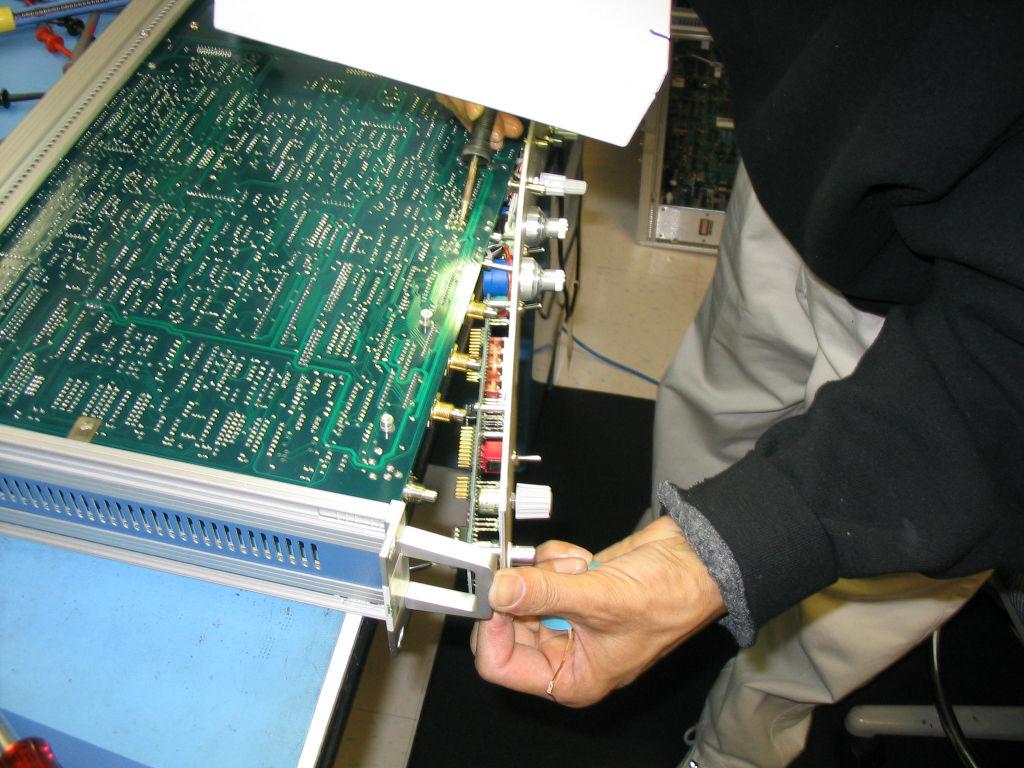
14 STEP 14:

15 Turn unit right-side up. Pry open the front panel (see picture above) and pull the switch out. STEP 15: Clean the holes from the switch on the PCB. Use a solder iron with a Kimwipe. The holes need to be completely free of obstructions. STEP 16: Throw away the old switch. STEP 17: Put the new switch into position. You will need to gently pry open the front panel.

16 STEP 18: Before soldering the switch on, put hex screws back on front panel Series Resistance potentiometer. This will ensure that the front panel is snugly attached before proceeding further. STEP 19: Check top and bottom to make sure that the polarity switch fit into its holes:

17 STEP 20: Solder legs of polarity switch to PCB. STEP 21: Reattach jumpers to front panel and main board (from STEP 8). STEP 22: Before proceeding further, this is a good point to stop and test the functionality of the switch. Using the front panel Holding Command and observing Vm on the meter, make sure that the switch works in the positive (+), negative (-) and OFF positions. STEP 23: Clean the solder joints you make using a sharp scraper and a light metal brush:


18 STEP 24:

19 Replace bottom front bar. Insert side screws first, then loosely attach bottom 4 screws, and finally the front panel screws. Tighten the bottom screws: STEP 25: Replace top front bar. Insert side screw first; then front screws:

20 STEP 26: Make another round to make sure all screws from top and bottom bars are tight. STEP 27: Make sure the wire going from the front panel Scaled Output is in its groove on the side panel. Use some tape if necessary

21 STEP 28: Place the remaining hex screws on the front panel pots and switches.

22 STEP 29: Replace the dials (leave the Series Resistance last). As you place the dial back on, make sure that its setting is in its lowest position before tightening it. You will have to use one hand to keep the switches from turning as you tighten them (see picture). Put the caps back on.


23 STEP 30:
 to turn the dial completely counterclockwise.")
24 Replace the Series Resistance dial. The first step is to use the forked screwdriver to tighten the dial while using your other hand to keep the zero reading position at the top. Once the dial is tight, use a sharp object (such as the tip of an Allen wrench) to turn the dial completely counterclockwise. Put the cap on and tighten it, again while keeping a zero reading position at the top. The dial in position, before tightening: The forked screwdriver in position:

25 After tightening the dial with the zero position at the top, using an Allen wrench to turn the dial completely counterclockwise:


26 Tightening the cap while keeping a zero position on the dials:

27 STEP 31: Replace the bottom cover. You may need to pop it in first: STEP 32: Replace all side panels by popping them in. Make sure that the side screws are tight or you won t be able to put the panels in.

28 STEP 33: Replace the top cover and you are done:

29
LITTLE NERD v1.1 Assembly Guide
 last update: 9. 3. 2016 LITTLE NERD v1.1 Assembly Guide bastl instruments.com INTRODUCTION This guide is for building Little Nerd module from Bastl Instruments. It is good to have basic soldering skills
Basic steps to time the Gammill quilting machine s rotary sewing hook
 Basic steps to time the Gammill quilting machine s rotary sewing hook 1.) Turn the machine off and unplug it. 2.) With the needle bar in the raised position, remove the bobbin and bobbin case. 3.) Remove
MAG-CONV Basic, 48, 48R & Midline Front Mount
 Parts Required: Tools Used: Mag Wheels Brakes Brake Rods Mounting Bracket Anti Tippers 7/16" Wrench Screw Driver Rubber Mallet 5/8 Wrench 5mm Allen Wrench Step Execution Figures 1 Remove front 5" total
Strata. urniture. Adriana Instructions. Parts in the Arm Box: Parts in the Body Box: Watch our assembly videos at
 1A Watch our assembly videos at www.strataf.com/videos Parts in the Arm Box: Arm - Outside View Arm - Inside View 1B Parts in the Body Box: Back Deck x 1 Seat Deck x 1 with the Feet attached Back Panel
KASTLE v1.5 - Assembly Guide
 last update: 14. 12. 2017 KASTLE v1.5 - Assembly Guide bastl-instruments.com INTRODUCTION Welcome to the assembly guide for the Kastle kit - mini modular synthesizer. It is suitable for beginners. It is
MULTI-ACTIVITY PLAY TABLE
 ASSEMBLY INSTRUCTIONS! WARNING: CHOKING HAZARD - Small parts. Not for children under 3 years.! CAUTION: Adult assembly required. C 2006 Melissa and Doug, Inc. All Rights Reserved www.melissaanddoug.com
MODULAR BUMPER INSTALLATION MANUAL
 MODULAR BUMPER INSTALLATION MANUAL Parts List* 1 Center section 1 Side extension, passenger / right 1 Side extension, driver / left 1 Side cap, passenger / right 1 Side cap, driver / left 1 Brush guard,
Not Included: Knob - Save From Original Pot
 Replacement Illuminator - Nikon Labophot dditional Items Included ut Not Shown: PN 056 Hex Key.5mm (for pot install - M screws) PN 060 Hex Key mm Short rm (for microscope bottom cover) PN 099 Hex Key 5mm
Removing outter components
 Y Axis Motor Replacement Replacing the Y axis motor is a process that requires the individual to be somewhat mechanically inclined and can follow detailed instructions. If any of the following steps are
Jenny Legs Assembly Instructions
 Jenny Legs Assembly Instructions R EXTENDED PHILLIPS BIT MM ALLEN WRENCH 6MM HEX DRIVE /" 007 Steelcase Inc. Grand Rapids, MI 90 U.S.A. Printed in U.S.A. Page of 6 88000 Rev F Jenny Club Instructions:
ELECRAFT Application Note
 ELECRAFT Application Note Front Panel Microphone Circuit Modification Revision A, November 12, 2008 Copyright 2008, Elecraft, Inc., All Rights Reserved Background Some K3 owners have noted distorted transmit
ELEVEN COLLABORATIVE. CONFERENCE TOPS Assembly Instructions
 ELEVEN COLLABORATIVE Table of Contents SUPPORT BRACE ASSEMBLY.... 3 TABLE BASE FRAME ASSEMBLY.... 4 LEG ATTACHMENT.... 5 TOP JOINING PLATE ASSEMBLY... 6 TOP CLAMP/TOP SPACER INSTALLATION.... 7 TOP PLACEMENT
Fortress Fe Posts must always be secured to the deck framing. Fortress Fe Posts should never be attached to only the deck boards.
 Installation Instructions for Fortress Horizontal Cable Panel System with UB-05 Brackets and Fe Posts It is the responsibility of the installer to meet all code and safety requirements, and to obtain all
BL-ER-P Ethernet Radio Unit for Pedestal Installation Guide
 Assemble the Antenna Riser 1. Remove the antenna riser assembly and the antenna from its packaging. 2. Remove the plastic cap, the nut, and the lock washer from the stem of the antenna. 3. Put the stem
Removing and Replacing the Y-truck
 Service Documentation Removing and Replacing the Y-truck To remove and replace the Y-truck you will need the following tools: 4mm Allen wrench 12mm stamped flat wrench #2 Phillips screwdriver (magnetic
Explorer Wiring Kit (assembled)
") Explorer Wiring Kit (assembled) For Vintage, Firestorm & Standard Series Please Read All Instructions Before Beginning. Tools you will need: Soldering Iron (35 watt preferably) Solder Wet Sponge Wire Clippers
Explorer Wiring Kit (assembled) For Vintage, Firestorm & Standard Series Please Read All Instructions Before Beginning. Tools you will need: Soldering Iron (35 watt preferably) Solder Wet Sponge Wire Clippers
WATCH VIDEO INSTALL! HOW-TO INSTALL CV-TL-80S-EB. Page: Instructions for Installation on: Toyota Land Cruiser 80 Series
 Clearview Towing Mirrors (Electric Power Adjustable) CV-TL-80S-EB Instructions for Installation on: Toyota Land Cruiser 80 Series 1990-1997 Page: 1 OF 13 Clearview s premiere line of replacement towing
mila-wall (Series100) General Operating Instructions page 1 of 15
 General Operating Instructions page 1 of 15") mila-wall (Series100) General Operating Instructions page 1 of 15 Step #1: Before setting up walls, lower adjustable leveling feet on each panel approximately 1". This will allow access to the threaded
mila-wall (Series100) General Operating Instructions page 1 of 15 Step #1: Before setting up walls, lower adjustable leveling feet on each panel approximately 1". This will allow access to the threaded
Motorized or Crank Operated Fortress Zipper Track Shade with Housing and Side Track Installation Instructions
 Motorized or Crank Operated Fortress Zipper Track Shade with Housing and Side Track Installation Instructions Tools Needed Drill 3/8 Metal Drill Bit ¼ Masonry Drill Bit Measuring Tape Pencil 4 Level Phillips
The Phoenix. Professional Quilting Frame. Copyright January 1, 2016 Jim M. Bagley, GraceWood, Inc (Reproduction Prohibited) Version 2.
 Version 2.") The Phoenix Professional Quilting Frame Copyright January 1, 2016 Jim M. Bagley, GraceWood, Inc (Reproduction Prohibited) Version 2.1 1 The Phoenix Professional Quilting Frame Parts List Box 1...3 Box
The Phoenix Professional Quilting Frame Copyright January 1, 2016 Jim M. Bagley, GraceWood, Inc (Reproduction Prohibited) Version 2.1 1 The Phoenix Professional Quilting Frame Parts List Box 1...3 Box
US RACK, Inc Falcon Drive, Madera, CA
 US RACK, Inc - 2850 Falcon Drive, Madera, CA 93637-559-661-3050 INSTALLATION AND USE INSTRUCTIONS for Long-John Extension Ladder Rack WARNING: Do NOT attempt to install or use this rack without following
PAC-12 Kit Contents. Tools Needed Soldering iron Phillips screwdriver Wire stripper Wrenches, 7/16 and 1/2 Terminal crimp tool Pliers Solder
 PAC-2 Kit Contents Part Quantity Screws: 8/32 x 3/8 Screws: 8-32 x 5/6 Screw: 8-32 x /4 #8 internal tooth washers #8 solder lug ring terminals Bolt: Aluminum, /4-20 x.5 /4 internal tooth washer Nut: Aluminum
OpenROV. Guide 3 - Electronics. We will now move to the assembly of the electronics that will control the ROV. Written By: OpenROV
 OpenROV Guide 3 - Electronics We will now move to the assembly of the electronics that will control the ROV. Written By: OpenROV 2017 openrov.dozuki.com Page 1 of 33 INTRODUCTION We will introduce soldering
16 STEEL CABINET HEAVY DUTY
 HEAVY DUTY 16 STEEL CABINET ASSEMBLY INSTRUCTIONS SIX DRAWER BASE CABINET 12-2013 Parts List Part No Description Qty Image SIX DRAWER BASE CABINET Part No Description Qty Image SB-1 Cabinet Body 1 SLD-01
2-Door EXO-Top Roof Rack System
 Page 1/29 Part 13516.01 2-Door EXO-Top Roof Rack System! WARNING The EXO-Top Roof Rack System is rated to a dynamic 300 lb, evenly distributed load. Further loading could result in serious injury or death.
Wildeck Overhead Safety Gate. General
 Wildeck Overhead Safety Gate General Safe and efficient movement of palleted material to and from your mezzanine is a requirement, and the Wildeck Overhead Safety Gate delivers every time. Workers on the
Spiderbeam Balun Construction Guide
 BALUN CONSTRUCTION GUIDE Ver. 1.0 1 The components of the Balun Kit are in a plastic bag. Most of the components are inside the plastic case of the balun. The aluminum U-profile and the RG-142 Teflon Coax
Installation Instructions
 Installation Instructions Walk-in Shower Screen with 180 o Return Panel (700 + 350mm & 900 + 350mm) Installation Instructions Parts supplied A B C D Wall Channel (x1) Wall fixing screw (x6) Return Straight
Vir Stil Console Lavatory INSTALLATION INSTRUCTIONS
 THANK YOU FOR CHOOSING KALLISTA We appreciate your commitment to Kallista quality products. Please take a moment to review this manual before you install your Kallista product. If you encounter any installation
High Rise Sit-Stand Desk Converter
 High Rise Sit-Stand Desk Converter Assembly Instructions for Model DC300 Patent Pending PRE-ASSEMBLY Please read all instructions before beginning assembly. We strongly recommend you watch the video at
AUTOMATIC ADVANCE MANUAL
 AUTOMATIC ADVANCE MANUAL AVL Looms, Inc. 3851 Morrow Lane, Suite #9 Chico, CA 95928-8305 530 893-4915 530 893-1372 fax # info@avlusa.com www.avlusa.com Copyright 2009 TABLE OF CONTENTS Page # I. Parts.........................
Assembly Instructions Nevins Phone Booth
 Assembly Instructions Nevins Phone Booth Included Hardware Tools Required supplied by installer Drill & Bit Bolt A - (16) 1/4-20 x 1-1/2 hex head Bolt B - (20) 1/4-20 x 2-1/2 phillips head Screw 1 - (24)
INSTALLATION MANUAL FRONT. See pages 2 and 3 of this manual for configuration options. Level of Difficulty. Product Photo (center section only)
") INSTALLATION MANUAL FRONT Level of Difficulty Moderate Product Photo (center section only) All hardware listed below will be provided with the bumpers center section. Additional hardware will be supplied
INSTALLATION MANUAL FRONT Level of Difficulty Moderate Product Photo (center section only) All hardware listed below will be provided with the bumpers center section. Additional hardware will be supplied
Using the Parkwood Instruments KXer-Single Paddle
 Page 1 Using the Parkwood Instruments KXer-Single Paddle Parkwood Instruments 2626 Parkwood Drive Speedway, IN 46224 Makers of Innovative Keys, Paddles, and Bugs Web Address: http://wb9lpu.googlepages.com
/ Rudder Installation Guide
 / Rudder Installation Guide Parts List Part # Part Description Qty Part # Part Description Qty 1030 Plastic Bead 1 1195 Rope; 1/8" Black Nylon 1 @ 9 1044 1/4-20 x 5/8" Pan Head Bolt 2 1353 Sliding Track
Riverside. Windhaven Queen Storage Bed Assembly Instructions
 Queen Storage Bed Page 1 of 7 2 pcs. 4 pcs. 4 pcs. 4 pcs. 2 pcs. 5/0 Queen Storage Bed 50773 -- 5/0 Storage Footboard w/platform Note: The 50773 Storage Footboard can be used with the 50770 Panel Headboard
Installing the Profile Privacy Panel. Assemble top mounting bracket. Prerequisites. Tools
 Installing the Profile Privacy Panel Complete these instructions to install the Profile Privacy Panel. Privacy panels are available in various heights to match tiers and include mounting hardware for slat
Wall Mount Assembly and Mounting Guide (55 /84 )
") Microsoft Surface Hub Wall Mount Assembly and Mounting Guide (55 /84 ) For mounting on a wall with wood studs These instructions assume wood-stud wall construction with 2-by-4 studs spaced 16 inches apart,
Microsoft Surface Hub Wall Mount Assembly and Mounting Guide (55 /84 ) For mounting on a wall with wood studs These instructions assume wood-stud wall construction with 2-by-4 studs spaced 16 inches apart,
Assembly Instructions for model: VMPR1
 Assembly Instructions for model: VMPR1 Congratulations on your purchase! The VMPR1 ceiling mount provides a unique, simplified method of ceiling mounting inverted LCD/DLP projectors. Its low profile design
Corded Honeycomb Shades
 Corded Honeycomb Shades Remove shade from package. Save packaging until shade is installed and working to your satisfaction. Level Tape Measure Pencil Power drill Screwdriver s for different mounting surface:
3,500/4,500lb. Vertical Cable Feighner Lift
 3,500/4,500lb. Vertical Cable Feighner Lift CAUTION - PUT SAFETY FIRST 1. Before attempting to install or operate this lift, study and fully understand the proper operating procedures and safety precautions
3-1/4 HP VARIABLE SPEED PLUNGE ROUTER
 IMPORTANT INFORMATION 2-YEAR LIMITED WARRANTY FOR THIS PLUNGE ROUTER KING CANADA TOOLS OFFERS A 2-YEAR LIMITED WARANTY FOR NON-COMMERCIAL USE. 3-1/4 HP VARIABLE SPEED PLUNGE ROUTER PROOF OF PURCHASE Please
Riverside. Harbor Hill Queen Storage Bed Assembly Instructions
 Queen Storage Bed Page 1 of 7 8 pcs. 8 pcs. 1 pc. 2 pcs. 3 pcs. 3 pcs. 4 pcs. 4 pcs. 4 pcs. 1 pc. 1 pc. 8 pcs. 8 pcs. 8 pcs. 2 pcs. 8 pcs. 1 pc. 25770 -- 4/6-5/0 Panel Headboard (NOTE: the 25775 Leather
INSTALLATION MANUAL PBL-UMP
 INSTALLATION MANUAL PBL-UMP Table of Contents Warning Statements... 4 Parts List... 5 Installation Tools... 5 Features... 7 Projector Preparation... 8 Bracket Installation... 10 Leveling the Mounting Bracket...
Clearview Railing System Installation Instructions
 Clearview Railing System Installation Instructions Disclaimer: AGS Stainless, Inc. has its Clearview Railing Systems designed by a professional engineer to meet the requirements of the latest national
HDL(M)6 Nut/Screw Assembly
6 Nut/Screw Assembly") HDL(M)6 Nut/Screw Assembly Remove, repair, and reassemble the nut and screw assembly in your HDL series double lock vise. In these instructions when we refer to the front of the vise or nut/screw assembly,
HDL(M)6 Nut/Screw Assembly Remove, repair, and reassemble the nut and screw assembly in your HDL series double lock vise. In these instructions when we refer to the front of the vise or nut/screw assembly,
compile system INSTALLATION GUIDE Updated January 2019
 INSTALLATION GUIDE Updated January 09 compile system Table of Contents Panels 0 Quick Connect Clips 0 Lock Clips 0 Panel Trims 0 Privacy Glass 0 Post Base Covers 04 Electrical 04 Power Distribution Harness
Model 333 Single Channel USB Chromatography Data System Relay ( Contact Closure ) Installation
 Installation") Remove the four screws holding the Model 333 A/D board in the stand-alone box. If the 333 is installed in a GC or HPLC, remove the four hex head screws from the outside of the instrument which secure the
Remove the four screws holding the Model 333 A/D board in the stand-alone box. If the 333 is installed in a GC or HPLC, remove the four hex head screws from the outside of the instrument which secure the
MOTORIZED STANDARD SHADE WITH CABLES Installation Instructions
 Tools Needed Drill Measuring Tape Pencil 2 Level Plumb Line ¼ Masonry Drill Bit Hammer Linesmans Pliers Cable Cutters Phillips & Flat-Head Screw Driver 11/32 Socket or Open End Wrench 5/32 Allen Wrench
Riverside. Oakmont Queen Storage Bed Assembly Instructions
 Queen Storage Bed Page 1 of 7 8 pcs. 8 pcs. 1 pc. 1 pc. 8 pcs. 8 pcs. 8 pcs. 8 pcs. 1 pc. 1 pc. 20270 --5/0 Sleigh Headboard 20274 --5/0-6/6 Bed Rails 20273 -- 5/0 Storage Footboard, Panels, Slats Queen
Fortress Fe Posts must always be secured to the deck framing. Fortress Fe Posts should never be attached to only the deck boards.
 Installation Instructions for FortressCable H-Series Cable Panel System With UB-05 Brackets and Fe Posts It is the responsibility of the installer to meet all code and safety requirements, and to obtain
INSTALLATION MANUAL PBC-UMS
 INSTALLATION MANUAL. PBC-UMS Premier Mounts 3130 E. Miraloma Avenue Anaheim, CA 92806 Phone: (800) 368-9700 Fax: (800) 832-4888 mounts@mounts.com www.mounts.com Rev. 01 PBL-110 Projector Mount Page 2 Installation
Riverside. Harbor Hill King Storage Bed Assembly Instructions
 King Storage Bed Page 1 of 7 8 pcs. 8 pcs. 1 pc. 2 pcs. 6 pcs. 3 pcs. 4 pcs. 4 pcs. 4 pcs. 1 pc. 1 pc. 2 pcs. 8 pcs. 8 pcs. 8 pcs. 8 pcs. 25780 -- 6/0-6/6 Panel Headboard (NOTE: the 25785 Leather Headboard
Standard Kit #1 (3-way switch)
") Standard Kit #1 (3-way switch) Please Read All Instructions Before Beginning. Tools you will need: Soldering Iron (35 watt preferably) Solder Wet Sponge Wire Clippers 3/8 Drill Bit 1/4 Drill Bit Variable
Standard Kit #1 (3-way switch) Please Read All Instructions Before Beginning. Tools you will need: Soldering Iron (35 watt preferably) Solder Wet Sponge Wire Clippers 3/8 Drill Bit 1/4 Drill Bit Variable
INSTALL LOAD BED TRACKS
 Universal LOAD BED TRAY & Load BArs TRBU001 / KRLBUNI1 INSTALL TIME: 2.5 Hours READ ME FIRST: Thank you for purchasing a Front Runner Slimline II Load Bed Rack or Load Bar Kit. Your Kit will contain the
STEP 1 STEP 6 STEP 5 STEP 1 STEP 3 STEP 4 STEP 7
 Step 1:Attach the tube join support by sliding in tube into legs, make sure height of the 2 legs are the same. Step 2:Attach the second join support in front of the tube join support using provided allen
Chapter 6 Frame And Lens Repairs
 Chapter 6 Frame And Lens Repairs 6.1 General Information All maintenance on the frame of the EXO Full-Face mask can be accomplished with common hand tools. 6.2 Lens Replacement Tools required: Dow DC-111
The ability to make basic voltage and resistance measurements using a digital multimeter
 Congratulations on your purchase of a new OneShot chassis! The PC01 OneShot combines a rugged enclosure, power supply, and discrete instrument DI in a compact 1/4U package. A few minutes of assembly are
Q-Zone Hoop-Frame. Assembly Instructions. Copyright July 11, 2018 Grace Company (Reproduction Prohibited) Version 1.8
 Version 1.8") Q-Zone Hoop-Frame Assembly Instructions Copyright July 11, 2018 Grace Company (Reproduction Prohibited) Version 1.8 Table of Contents Table of Contents... i Warranty... ii Parts List Box 1...iii Box 2...
Q-Zone Hoop-Frame Assembly Instructions Copyright July 11, 2018 Grace Company (Reproduction Prohibited) Version 1.8 Table of Contents Table of Contents... i Warranty... ii Parts List Box 1...iii Box 2...
CALLAS THERMOSTATIC SHOWER SET
 SKU(s): 925945 CALLAS THERMOSTATIC SHOWER SET BEFORE YOU BEGIN We recommend consulting a professional if you are unfamiliar with installing plumbing fixtures. Signature Hardware accepts no liability for
Assembly Instructions Nevins Phone Booth
 Assembly Instructions Nevins Phone Booth Included Hardware Tools Required supplied by installer Drill & Bit Socket Wrench Bolt A - (16) 1/4-20 x 1-1/2 hex head Bolt B - (20) 1/4-20 x 2-1/4 phillips head
MALEKO WALL-MOUNT FAUCET INSTALLATION
 SKU(s): 934146 BEFORE YOU BEGIN We recommend consulting a professional if you are unfamiliar with installing bathroom fixtures and plumbing. Signature Hardware accepts no liability for any damage to the
Baby Grande or Grande Crank Shade with Cables and Housing Installation Instructions
 Baby Grande or Grande Crank Shade with Cables and Housing Installation Instructions Tools Needed Drill 3/8 Metal Drill Bit Screwdriver (Flat & Phillips) Measuring Tape Pencil 4 Level Plumb Line ¼ Masonry
ABC V1.0 ASSEMBLY IMPORTANT!
 ABC V1.0 ASSEMBLY Before starting this kit, prepare the following tools: Soldering iron (15-20W will do), flush cutters, no.2 hex screwdriver or allen key and phillips screwdriver. Also briefly go through
Orion m Series Welding System User Manual
 Orion m Series Welding System User Manual Table of Contents Chapter 1: Setup and Assembly... p.5 What is in the Box... p.5 Darkening Lens & Power Supply Setup... p.5 Microscope Arm Setup... p.6 Microscope
STEP 1 : DESTROYER FRONT BUMPER INSTALL GATHER YOUR TOOLS AND LAY OUT YOUR PARTS... *shorty bumper to show hardware* Tools Required:
 DESTROYER FRONT BUMPER INSTALL JL STEP 1 : GATHER YOUR TOOLS AND LAY OUT YOUR PARTS... Tools Required: - Utility knife - 11/16 Deep socket - Ratchet - 11/16 Crescent wrench - Ratchet Extension - 1/4 socket
Thanks for shopping with Improvements! Wood Single Chaise Lounge Item #425994
 Thanks for shopping with Improvements! Wood Single Chaise Lounge Item #425994 Note: Read these instructions carefully before assembling. Find a clean, smooth area on which to work, such as a carpet, in
Closet Wall Drawer Unit
 88 5531 751 Closet Wall Drawer Unit A. B. C. Shelf D. E. F. For assembly see instructions in carton 88 5531 752. 88 5531 752 Closet Wall Drawer Unit G. H. I. Plinth M. Bottom L. N. 2 pc. J. K. O. Drawer
MODEL SK61732 COMPRESSOR SERVICE KIT
 MODEL SK61732 COMPRESSOR SERVICE KIT For use on 607 and 617 Model Compressors with.32 Stroke WARNING: Unplug the compressor before beginning disassembly. CAUTION: Improper assembly or use of damaged parts
BALANTINE WALL-MOUNT FAUCET INSTALLATION
 SKU(s): 911574, 911575 BALANTINE WALL-MOUNT FAUCET INSTALLATION BEFORE YOU BEGIN We recommend consulting a professional if you are unfamiliar with installing bathroom fixtures and plumbing. Signature Hardware
HEAVY DUTY 11 STEEL CABINET
 HEAVY DUTY STEEL CABINET ASSEMBLY INSTRUCTIONS ONE DRAWER BASE CABINET 05-206 Parts List Part No Description Qty Image ONE DRAWER BASE CABINET Part No Description Qty Image SB- Cabinet Body EH-0 Euro Hinge
Footprint Mobile Assembly Instructions
 Footprint Mobile Assembly Instructions 1998754 Revision -1 Complete Series Master Packet If you have any questions concerning these instructions, please call Kimball Office Customer Service. 20 Kimball
WILLIS WALL-MOUNT FAUCET INSTALLATION
 SKU(s): 924620 BEFORE YOU BEGIN We recommend consulting a professional if you are unfamiliar with installing bathroom fixtures and plumbing. Signature Hardware accepts no liability for any damage to the
SALEM ICE CABIN 80A MINI-BREAKER INSTALLATION
 Introduction Some Ice (House) Cabin trailers may operate slowly and/or stop operating after five seconds of use. The cause is the main power for the dual polarity solenoid, which is supplied by a 10AWG
Installation Guide. Mounting Kit for Mounting Philips Avalon CTS Cordless Fetal Transducer System on Wall, 2'' Post, Rail, or Slide-on Mounting Plate
 Installation Guide Mounting Kit for Mounting Philips Avalon CTS Cordless Fetal Transducer System on Wall, 2'' Post, Rail, or Slide-on Mounting Plate The purpose of this guide is to: 1. Describe mounting
Fortress Fe Posts must always be secured to the deck framing. Fortress Fe Posts should never be attached to only the deck boards.
 Installation Instructions for FortressCable H-Series Stair Panels with Simplified Stair Bracket SSB-05 and Fe Posts It is the responsibility of the installer to meet all code and safety requirements, and
Step 1: The larger tower box contains the tower machine, a set of Silver 100 Lid Keys, and a set of Black 002 Coin Box Keys
 2 3 Step 1: Each tower is shipped as two boxes the large tower box and the smaller stand box. Open each of the boxes and inventory each of the parts before starting assembly to ensure all parts have arrived.
ROS-APT Caucus Plinth Table with Trough Note: Details apply, however the actual configuration of your table may vary from what is depicted here.
 ROS-APT Caucus Plinth Table with Trough Note: Details apply, however the actual configuration of your table may vary from what is depicted here. Parts List - Tables Tops, Top Insert Panels and Base panels
REPAIR INSTRUCTIONS. Cat. No Cat. No MILWAUKEE ELECTRIC TOOL CORPORATION. SDS Max Demolition Hammer. SDS Max Rotary Hammer
 Cat. No. 9-0 SDS Max Demolition Hammer Cat. No. -0 SDS Max Rotary Hammer MILWAUKEE ELECTRIC TOOL CORPORATION W. LISBON ROAD BROOKFIELD, WISCONSIN 00-0 8-9-0 d 000 8-9-0 d Special Tools Require Forcing
Continuum Frame Assembly Instructions
 Continuum Frame Assembly Instructions Copyright January 1, 2017 Jim M. Bagley, GraceWood, Inc (Reproduction Prohibited) Version 2.2 Table of Contents Continuum Frame Table of Contents... i Warranty...ii
BHJ Products, Inc. Parts List & Instructions
 Product Name: O-Ring Groove Cutter Adjustable Tool Block Upgrade Page 1 of 5 Prototype Kit Contents: 1x Adjustable Tool Block 1x Adjustable Tool Holder 1x Graduated Adjusting Screw 1x 1/8 Registration
Standard Kit #1 (5-way switch)
") Standard Kit #1 (5-way switch) Please Read All Instructions Before Beginning. Tools you will need: Soldering Iron (35 watt preferably) Solder Wet Sponge Wire Clippers 3/8 Drill Bit 1/4 Drill Bit Variable
Standard Kit #1 (5-way switch) Please Read All Instructions Before Beginning. Tools you will need: Soldering Iron (35 watt preferably) Solder Wet Sponge Wire Clippers 3/8 Drill Bit 1/4 Drill Bit Variable
This manual will aid in the assembly of the FireBall V90 and FireBall X90. The assembly of both machines will be identical, unless specified.
 This manual will aid in the assembly of the FireBall V90 and FireBall X90. The assembly of both machines will be identical, unless specified. Step #1 Lay all parts out to verify quantities. (2) 2 x 25-1/4
Bodyspray INSTALLATION INSTRUCTIONS
 Bodyspray P22077 P22079 2014 KALLISTA 1 of 8 THANK YOU FOR CHOOSING KALLISTA Bodyspray We appreciate your commitment to KALLISTA quality products. Please take a moment to review this manual before you
Installation instructions, accessories. Rails. Volvo Car Corporation Gothenburg, Sweden. Instruction No Version Part. No
 Instruction No Version Part. No. 8685942 1.0 Rails J8401014 Page 1 / 9 Equipment A0000162 A0000161 J8401006 Page 2 / 9 INTRODUCTION Read through all of the instructions before starting installation. Notifications
ASSEMBLY AND ADJUSTMENT
 EPPA MONITOR ARM EPPA Rev A 10/17 Model EPPA-XXX ASSEMBLY AND ADJUSTMENT EPPA MONITOR ARM PARTS AND TOOLS PLEASE REVIEW these instructions before beginning the assembly and adjustment procedures. Check
FLIP TARP SINGLE & DOUBLE UNDERBODY TRAILERS
 1-800-248-7717 1002 N. 15th Street, Middlesboro, KY 40965 FLIP TARP SINGLE & DOUBLE UNDERBODY TRAILERS INSTALLATION INSTRUCTIONS Congratulations on your purchase of a Mountain Flip Tarp Trailer system.
Workbench Instructions for Assembly
 Workbench Instructions for Assembly FlexWorks is a trademark of Lista International Corporation. Making Workspace Work is a trademark of Lista International Corporation. Document Number: MD002A3 Print
HARVIL 3-IN-1 FLIP TABLE ASSEMBLY INSTRUCTIONS
 HARVIL 3-IN-1 FLIP TABLE ASSEMBLY INSTRUCTIONS NGD1018/1022 THANK YOU! Thank you for your purchase of this Harvil product. We work around the clock and around the globe to ensure that Harvil products maintain
iphone 1st Generation Battery Replacement Written By: irobot ifixit CC BY-NC-SA Page 1 of 15
 Written By: irobot ifixit CC BY-NC-SA www.ifixit.com Page 1 of 15 INTRODUCTION Battery not lasting long? Swap it out (requires soldering). TOOLS: Probe and Pick Set (1) Desoldering Braid (1) SIM Card Eject
Model: SS660-OB Stainless Steel Floor Scale Series. Installation, Set-Up and Operation Manual
 SCALE WORKS, INC. Model: SS660-OB Stainless Steel Floor Scale Series (On-Board Junction Box) Installation, Set-Up and Operation Manual Cambridge Scale Works, Inc. P.O. Box 670 Honey Brook, PA. 19344 (800)
S OLAR RADIATION S HIELD MANUAL
 S OLAR RADIATION S HIELD MANUAL This instruction manual is designed to take you step-by-step through the process required to assemble and mount your Solar Radiation Shield. Please take the time to read
Driver/Left Top. Support Bracket
 PARTS LIST: 1 Grille Guard 8 10mm Lock Washers 1 Driver/Left Frame Bracket 8 10mm Hex Nuts 1 Passenger/Right Frame Bracket 2 8-1.25mm x 25mm Button Head Bolts 1 Driver/Left Bottom Support Bracket 2 8mm
READ CAREFULLY - FAILURE TO FOLLOW INSTRUCTIONS AND SAFETY RULES MAY RESULT IN SERIOUS INJURY
 Owner s Manual LSV50120B LS5000B leg bundle LS5021B post bundle LS5022B cradle bundle V50120B straight LS5003B spreader bundle LS5004B bunk bundle LS4005B accessory box LS2005B wheel LS5007B diag bundle
PULL-THRU USER S MANUAL
 PULL-THRU USER S MANUAL G14x Part # 310 120 177 G20 Part # 310 120 188 G20x Part # 310 120 186 G40x Part # 310 120 163 TABLE OF CONTENTS SECTION 1 PCB DESIGN AND MOUNTING SECTION 2 MOUNTING ADAPTER TO
A A A
 Hatsan Escort GA Akita Adjustable A..0.03 A..0.03 A..30.03 3 Four Position Adjustable Scorpion Recoil Pad Adjustable Soft Touch Padded Cheekrest 3 70.0795.0 Hatsan Escort GA Akita Adjustable [] M8 x.5
Giraud Tool Company, Inc.
 Motor Upgrade for Gracey Trimmer This package is intended to allow the user to upgrade their Gracey trimmer with a higher rpm motor and convenience features not found in the production offering. This upgrade
SAFETY INSTRUCTIONS. Wear protective clothing, including safety glasses and steel toe boots.
 SAFETY INSTRUCTIONS Wear protective clothing, including safety glasses and steel toe boots. DO NOT allow loose clothing or long hair near machine operations. Keep work site and machine clean. Use brush
Traditional Wall Mounted Potfiller
 TOOLS NEEDED FOR INSTALLATION 1/4 hex wrench (provided in installation kit) 3/32 hex wrench (provided in installation kit) Pencil or marker PTFE tape Small level, or carpenters square Power Drill with
OPERATIONAL MANUAL V1.0. Removing/Replacing Blades
 OPERATIONAL MANUAL V1.0 BLUEROCK WS-212 Wire Stripper Removing/Replacing Blades CAUTION!! IMPORTANT!! DANGER!! WARNING!! DISCONNECT MACHINE FROM POWER BEFORE PROCEEDING!! Estimated Completion Time: 90