Specifications Service Manuals
|
|
|
- Cameron Jefferson
- 5 years ago
- Views:
Transcription
1 Specifications Service Manuals
2 Specifications Calculation of max. acceleration a= F m Calculation of max. acceleration distance s= v x t 2 Calculation of max. acceleration time t= v F= belt tension (N) a a= acceleration (m/s²) m= mass (kg) v= velocity (m/s) s= distance (m) t= time (s) Type t a > 0,2 s t a < 0,2 s Minimum safty factor safty factor length strength F max (N) F 1,5 (N) max (N) 1,5 (N) (N) Belt size ELZ M 12 ELZZ M 09 ELZ, ELZT, ELSD, ELZU, ELZG 40, ELSZ 30/ M 15 ELZ, ELZT, ELSZ, ELSD, ELZU, ELZG 60, ELHZ, ELVZ 60 /80 DLZ 120 QLZ, QSZ 80 / QLSZ, QSSZ M 25 ELZZ M 12 ELZZ M 20 ELZ, ELZT, ELSZ, ELSD, ELZU, ELZG 80, DLZ, DSZ 160 / DLZT, DSZT, DLSZ 120 QLZ, QSZ M 30 ELHZ, ELVZ, ELZW M 48 ELZ, ELZT, ELSZ, ELSD, ELZG 100, QLZ, QSZ 100 DLZ 200 / DLSZ, DSSZ M 50 ELZ M 70 Weights Sizes Guidebody profile Internal profile guide rod Belt per pulley Toothed rack Standard carriage Carriage profile Coupling 30 1,07 kg/m - 0,15 kg/m 0,037 kg/m 0,06 kg - 0,176 kg 1,78 kg/m 0,007 kg 40 1,89 kg/m - 0,22 kg/m 0,074 kg/m 0,14 kg 0,70 kg/m 0,520 kg 3,49 kg/m 0,010 kg 60 3,83 kg/m - 0,61 kg/m 0,123 Kg/m 0,39 kg 0,81 kg/m 1,565 kg 7,49 kg/m 0,040 kg 80 7,40 kg/m - 0,88 kg/m 0,256 kg/m 1,04 kg 1,13 kg/m 2,644 kg 12,79 kg/m 0,085 kg 80S 7,40 kg/m - 0,88 kg/m 0,256 kg/m 1,04 kg 1,13 kg/m 3,520 kg 13,95 kg/m 0,085 kg ,3 kg/m - 1,58 kg/m 0,355 Kg/m 0,48 kg 2,75 kg/m 6,550 kg 19,98 kg/m 0,200 kg ,54 kg/m - 2,47 kg/m 0,480 kg/m 1,62 kg - 12,100 kg 28,05 kg/m 0,395 kg DL 120 5,61 kg/m 1,52 kg/m 0,22 kg/m 0,123 Kg/m 0,39 kg - 1,100 kg 4,15 kg/m 0,040 kg DL ,34 kg/m 3,73 kg/m 0,61 kg/m 0,256 kg/m 0,86 kg - 3,280 kg 7,99 kg/m 0,085 kg DL ,55 kg/m 3,48 kg/m 0,61 kg/m 0,355 Kg/m 0,688 kg - 4,950 kg 10,99 kg/m 0,200 kg DS ,52 kg/m 3,48 kg/m 1,40 kg/m 0,256 kg/m 0,86 kg - 2,250 kg 7,99 kg/m 0,085 kg QL 60 3,29 kg/m - 0,22 kg/m 0,123 Kg/m 0,39 kg - 0,456 kg 2,05 kg/m 0,040 kg QL 80 7,05 kg/m - 0,61 kg/m 0,256 kg/m 1,04 kg - 1,229 kg 3,85 kg/m 0,085 kg QL ,45 kg/m - 0,61 kg/m 0,355 Kg/m 0,688 kg - 2,920 kg 5,49 kg/m 0,200 kg QS 60 3,79 kg/m - 1,40 kg/m 0,123 Kg/m 0,39 kg - 0,860 Kg 2,05 kg/m 0,040 kg QS 80 6,82 kg/m - 2,40 kg/m 0,256 kg/m 1,04 kg - 2,339 kg 3,85 kg/m 0,085 kg QS ,55 kg/m - 3,20 kg/m 0,355 Kg/m 0,688 kg - 4,320 kg 5,49 kg/m 0,200 kg
3 Specifications Calculation of torsional twist x Nm x m f = L x M t max. x I p [ Nm x m ] f = max. twisting angle ( ) L = unit length M t max = max. torque (Nm) I p = see table ( /Nm²) Aluminium profiles Stiffness F25 (250 N/mm²) Thickness of anodizing coat20 to 30 mm Size I p Faktor Size I p Faktor Size I p Faktor EL 30 0,49000 /Nm x m DL 120 0,03282 /Nm x m QL 60 0,02995 /Nm x m EL 40 0,18000 /Nm x m DL 160 0,01286 /Nm x m QL 80 0,01257 /Nm x m EG 40 0,14000 /Nm x m DL 200 0,00787 /Nm x m QL 100 0,00705 /Nm x m EL 60 0,05765 /Nm x m DS 160 0,01336 /Nm x m QS 60 0,03797 /Nm x m EG 60 0,04387 /Nm x m QS 80 0,01563 /Nm x m EL 80 0,01463 /Nm x m QS 100 0,00644 /Nm x m EG 80 0,01511 /Nm x m EL 100 0,00492 /Nm x m EL 125 0,00616 /Nm x m Diagram for maximum rpm of screw units Ball Screw units Acme Screw units n max. = table value x 0,8
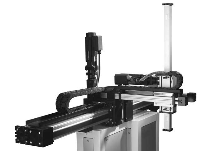
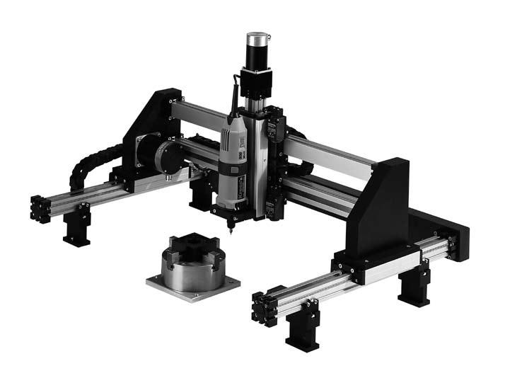
4 Applications in use
5 Service Manual for EL Units
 and push the wiper end plate (4) to the side.")
 of carriage (5) for greaser nipple. The ball screw nut can be filled with grease gun. For mass of greasing look at table below.")
6 Service Manual for EL units Lubrication Acme Screw, sizes EG / EL 30, 40 - Drive the carriage to one side - To reach screw, unscrew set screw (3) - Lift the coverband (6) - Now grease screw with a slim brush. Ball Screw, sizes EG / EL 30, 40 - Unscrew the cylindric screws (1) and push the wiper end plate (4) to the side. - Unbend screws (2), push slide (5) to other side - Unscrew the grub screws (3) and lift the coverband (6). - Grease can be filled now with grease gun. For mass of greasing look at table below. Screw, sizes EG 60, 80 / EL Look at wiper end plate (4) of carriage (5) for greaser nipple. The ball screw nut can be filled with grease gun. For mass of greasing look at table below. Screw greasing every working hours. Type Pitch Regreasing Type Pitch Regreasing 30 Kg 08 x 2,5 0,01 g 60 Kg 20 x 05 3,00 g 40 Kg 16 x 05 1,33 g 80 Kg 25 x 25 3,00 g 40 Kg 16 x 10 0,84 g 80 / 100 Kg 32 x 05 3,00 g 60 Kg 25 x 05 2,00 g 80 / 100 Kg 32 x 10 4,00 g 60 Kg 25 x 10 3,00 g 100 Kg 32 x 32 4,00 g 60 Kg 20 x 20 3,00 g 125 Kg 40 x 10 4,00 g
, where the tanks for the strippers can be filled with an oil gun. Viscosity of oil: 200 mm²/s, T= 40 C.")
7 Service Manual for EL units Lubrication, Changing Cover Band Guiding rods EL Rods will be greased by the strippers of carriage. There are 2 oil nipples in each wiper end plate (4), where the tanks for the strippers can be filled with an oil gun. Viscosity of oil: 200 mm²/s, T= 40 C. Interval of greasing depends on environmental conditions, min. once a month. Minimum stroke must be same than length of slide. EL 100, 125 Rollers should be greased each working hours or each 6 months with a grease gun. For greaser nipple look at the eccentric at carriage bottom. Use roller grease. Changing cover band EL 100, Unscrew cylindric screws (1), push plastic wiper endplate (4) to one bearing-block (7), - Unbend grub screws (2), push carriage (5) to other side - Unscrew screws (3) and pull out the coverband (6), size 100/125 units have an additional cover-band leader(9),which is the guide for the cover-band. - Mount the new coverband, fix the screws (3) at one side, tense the band with a pointed pliers and fix the screws (3), - Fix the carriage by the grub screws (2) and mount the wiper end plate (4).
8 Service Manual for EL units Changing Cover Band Changing cover-band and plastic guide roller against new slider system ELT / ELK 60, 80 - Unscrew cylindric screws (1) and dismount cover cap (2) on one side of the carriage (4). - Unscrew grub screws (3) on one side of the carriage (4). - Destroy the plastic guide roller (6) with a cutting nipper. - Be careful, don t destroy the hardened straight pin (7)!!!Attention!!!! Plastic guide roller can crack!!!! - Be sure that no fragments fall into the guiding-profile. - Pull out cover-band (8) out of the leading-nut receiver (10). - Dismount the plastic keys (9). - Mount and push in the cover-band (8) again like before (under the hardened straight pins (7). - Hook the plastic slider (11) under the straight pin (7) with the flat side to the middle of the carriage. - Fix the cover-band (8) on one side with the grub screw clamping (5) at the bearing block (12). - Tension the cover-band (8) from the opposite side of the unit and fix it with the grub screw clamping, too.
, - Mount the new coverband, fix the screws (3) at one side, tense the band with a pointed pliers and fix the screws (3), - Mount the wiper end plate (4).")
 on both sides of carriage (5) - Push the wiper end plates (4) to the side, - Unscrew the grub screwes (2) and pull out the old")
9 Service Manual for EL units Changing Cover Band Changing cover band size EL / EG 30, 40 - Unscrew cylindric screws (1), push plastic wiper endplate (4) to the side, - Unscrew screws (3) and pull out the coverband (6), - Mount the new coverband, fix the screws (3) at one side, tense the band with a pointed pliers and fix the screws (3), - Mount the wiper end plate (4). Changing cover band ELVZ / ELHZ 100, 125 S 2 Same mounting as ELT/ELK. Important: Measure the distance s between the corner of carriage and the head of the grub screw for belt-tension! Changing cover band ELHZ / ELVZ 60, 80 - Unscrew cylindric screws (1) on both sides of carriage (5) - Push the wiper end plates (4) to the side, - Unscrew the grub screwes (2) and pull out the old coverband (6), - Push the new coverband under both sliding block (8) in the carriage (5) and wiper end plates (4) into the bearing block (1) - Fix the grub screw (3) on one side, - Tense the coverband with a pointed pliers and fix the screws (3) on the opposite side.
 of the wiper endplate (4) and push it to the other bearing-block (7). - Pull the spring balance with force of table and measure the sag (f) of the belt.")
 must have the same distance between the corner of the carriage (5) and the head of the grub screw (2). - The grub screws (2) have to be secured by bonding.")
10 Service Manual for EL units Belt, Adjusting the Rollers Belt tension ELZ - Push the carriage (5) close to one bearing-block (7). - Unscrew grub screws (2) of the wiper endplate (4) and push it to the other bearing-block (7). - Pull the spring balance with force of table and measure the sag (f) of the belt. Compare the measured value with the table. - Tense or release the belt by the grub screws (2). - Both grub screws (2) must have the same distance between the corner of the carriage (5) and the head of the grub screw (2). - The grub screws (2) have to be secured by bonding. - Measure the distance (s) with a metal rule. - Mount the wiper endplate (4). Size Force N N N N N N Adjusting the rollers, sizes EL 40, 60 Adjusting the rollers, sizes EL 30, 80, 100, Fasten eccentric bolt with screw key (1) - Unscrew screw with hexagon socket screw key (2) as far as eccentric bolt can be turned, upper surface is stamped, broken line of stamp (3) must coincide with drawing groove of slide - Adjust at other side without initial tension - Stamps must be in same position and eccentric bolt must be adjusted into right direction. 10
11 Service Manual for D and Q Units 11
. - Insert the regreasing adapter (10) into the lubrication hole of the leading-nut receptacle (9). - Regrease now with grease gun.")
 and unscrew set screws (5). - Push carriage (6) to the side. - Release the set screw (7) and remove it using the sliding nut.")


12 Service Manual for D Q units Lubrication Leading-nut, size DLT/DLK 120, Drive the carriage to the service position (1). - Remove the fillister head screws (2) and dismount cover cap (3). - Remove the middle slider (4). - Insert the regreasing adapter (10) into the lubrication hole of the leading-nut receptacle (9). - Regrease now with grease gun. For the quantity of grease see table below. Leading-nut, size DLT/DLK / DST/DSK Drive the carriage to the service position (1). - Remove the fillister head screws (2) and dismount cover cap (3). - Remove the middle slider (4) and unscrew set screws (5). - Push carriage (6) to the side. - Release the set screw (7) and remove it using the sliding nut. - Pull out and lift the cover band (8), now the lubrication hole is visible in the leading-nut receptacle (9). - Regrease with grease gun. For the quantity of grease see table below. Screw greasing every working hours. Guiding rods DL 120, 160, 200 Runner blocks DS 160 Type Pitch Regreasing Type Pitch Regreasing 120 Kg 16 x 05 1,33 g 120/160 Kg 25 x 25 3,00 g 120 Kg 16 x 10 0,84 g 200 Kg 32 x 05 3,00 g 120 Kg 16 x 16 1,00 g 200 Kg 32 x 10 4,00 g 120/160 Kg 20 x 20 3,00 g 200 Kg 32 x 20 4,00 g 120/160 Kg 25 x 05 2,00 g 200 Kg 32 x 32 4,00 g 120/160 Kg 25 x 10 3,00 g Guiding rods QL 60, 80, 100 Runner blocks QS 60, 80, 100 Greasing is carried out through an oiled felt insert. The felt can be regreased through lubrication nipples attached laterally to the ends of the roller packs. - Dismount cover cap (1) - Drive the carriage through the service position until you can see the first lubricating nipple (2) in the lubrication hole. - Regrease felt now with an oil gun. - Move the carriage to the second lubricating nipple and regrease here as well. Oils with a viscosity of approx. 200 mm²/s at T=40 C are recommended. The required regreasing intervals depend on environmental conditions, the standard recommendation is once per month. To ensure a sufficient lubrication, the minimum stroke must equal the carriage length, so that sufficient greasing is achieved also in the final positions. 12
 for middle cover band (5) at the opposite bearing block. - Pull cover band out of bearing block and turn it to the side.")
.")
 < 2500 2500-6000 < 2500 2500-6000 < 2500 2500-6000 Kraft / Force (N) 20 10 20 10 40 20 Changing cover band DLZ 120, 160, 200 / DSZ 160 - Drive the")
13 Service Manual for D Q units Belt and Coverband Belt tension adjustment DLZ 120, 160, 200 / DSZ Push the carriage (1) close to one bearing block (2). - Remove fillister head screws (3). - Unscrew set screws (4) for middle cover band (5) at the opposite bearing block. - Pull cover band out of bearing block and turn it to the side. - Use springe balance (6) to exert the applicable amount of force (see table) on the center of the belt and measure the sag (f). - Compare the measured value with the diagram below, and tense or release belt as required by tightening or unscrewing the set screws (7). - The set screws (7) must be bonded in place with screw locking device. - Both screws (7) must be screwed in to exactly the same level. Check with sliding caliper. Baugröße / Size Hub / Stroke (mm) < < < Kraft / Force (N) Changing cover band DLZ 120, 160, 200 / DSZ Drive the carriage to servicing position - Remove fillister head screws (1) and wiper end plate (2) - Size 160: Unscrew set screws (3) at both bearing-block plates (4) and pull the cover band out of the bearing block - Size 120: Unscrew set screws and remove them with T-nut - Remove sliders (5) and (6) from both sides of the carriage (7) - Pull the cover bands (8) out of the carriage - Insert the new cover bands into the carriage (7) - Thread the lateral sliders (6) onto the cover band and insert it into the carriage with middle slider (5) - Size 160: Tighten cover bands on one side of the bearing block with set screws (3), tense cover band (8) at the other bearing block using pliers and tighten with set screws (3) - Size 120: Insert T-nut together with set screw into the bearing block and tighten cover band with set screw. 13
 until the eccentric bolt can be turned. - Adjust the gap dimension (A) between carriage and guide body profile by turning the eccentric bolts (3).")
 to adjust the carriage free of play by the touch (without initial tension) - Ensure that the eccentric bolts are adjusted to the right.")
14 Service Manual for D Q units Eccentric Bolt Adjusting the rollers size DL 120, 160, Dismount cover cap (5) from servicing hole - Fasten eccentric bolt with screw key (1) - Release screws with hexagon socket screw key (2) until the eccentric bolt can be turned. - Adjust the gap dimension (A) between carriage and guide body profile by turning the eccentric bolts (3). Turning towards + will increase the gap dimension. (DL120 approx. 1.8 mm, DL160 approx. 2.8 mm, DL120 approx. 3.0 mm). - Turn the eccentric bolts (4) to adjust the carriage free of play by the touch (without initial tension) - Ensure that the eccentric bolts are adjusted to the right. Adjusting the rollers size QL 60, 80, Dismount cover cap (5) from servicing hole - Fasten eccentric bolt with screw key (1) - Release screws with hexagon socket screw key (2) until the eccentric bolt can be turned. - Turn the eccentric bolts to adjust the carriage free of play (without initial tension) - Ensure that the eccentric bolts are adjusted to the right. 14
 on both sides of the unit and pull out the only the middle cover band (4) of the bearing-block plate ( 5).")
15 Service Manual for D Q units Belt Exchange S Changing belt of DL / DS 120, 160, Unscrew cylindric screws (1) and dismount cover caps (2) on both sides of the carriage. - Unscrew grub screws (3) on both sides of the unit and pull out the only the middle cover band (4) of the bearing-block plate ( 5). - Measure the reach of grub screws S (look at drawing) and make note of this value. - Unscrew grub crews (6) on both sides of the carriage. - Pull only the middle sliding blocks (7) out of the carriage. - Unscrew cylindric screws (8) at the bearing-block plates (5) and dismount them completely with the bearing-blocks (9) at both ends of the unit. - Pull out the belt-adjusters (11) completely with the belt out of the carriage (12) and the guiding-profile (10). - Unscrew the countersunk head screws (13) and dismount the belt-adjuster (11,14). Reconstruction of the unit in opposed order - Shorten the new belt to the length of the old one. - Push the belt with teeth side up to the carriage (10) into the slot of the guiding-profile (15) and push it with the ends thro ugh each bearing-block (8,9). - Mount the belt-adjusters (11,14) by the countersunk head screws (13) and lock them again with glue. - Push them again together with the belt into the guiding-profile (10) and then into the carriage (12). - Mount the bearing-block plates (8) again together with the bearing-blocks (9) at the ends of the unit. - Mount both belt-adjusters (11,14) with consideration of the reach of the grub-screws S and lock the grub screws (6) with glu e. - Pull the middle cover-band (4) through the carriage. - Pull in the middle sliding blocks (7) into slot of the carriage. - Mount the grub screws (3) on one side of the unit and tension the 3 cover-bands from the other side and fix them too by the grub-screws (3). 15
 on both sides of the carriage (8). - Unscrew cylindric screws (4) and the grub screws (5) at the bearing-block (6) and dismount them completely at both ends of the unit.")
16 Service Manual for D Q units Belt Exchange Changing belt of QL/QS 60,80,100 - Unscrew cylindric screws (1) and dismount cover caps (2) on both sides of the carriage. - Unscrew cylindric screws (3) on both sides of the carriage (8). - Unscrew cylindric screws (4) and the grub screws (5) at the bearing-block (6) and dismount them completely at both ends of the unit. - Pull out the belt-adjusters (7) completely with the belt out of the carriage (12) and the guiding-profile (10). - Press the belt sideways out of both belt-adjusters (7). - Pull the belt completely out of the bearing-blocks (6). Reconstruction of the unit in opposed order - Shorten the new belt to the length of the old one. - Push the belt with teeth side up to the carriage (8) into the slot of the guiding-profile (11) and push it with the ends through each bearing-block (6). - Press the belt again into the belt-adjusters (7). - Push them again together with the belt into the guiding-profile (10) and then into the carriage (8). - Mount the bearing-blocks (6) again. - Mount both belt-adjusters (7) and lock the cylindric screws (6) with glue. You have to tension the belt with dosed force and test the soft running of the pulleys by turning them. - Mount the cover caps (2) again East 49th Street Cleveland, OH USA (216) Toll Free: (800) Fax: (216) nook@nookind.com For more information visit: ISO 9001:2000 REGISTERED COMPANY 16
Our service team is at your disposal for further information. Franke GmbH Obere Bahnstr Aalen Germany Tel.: /920-0 Fax.
 Our service team is at your disposal for further information. Franke GmbH Obere Bahnstr. 64 73431 Aalen Germany Tel.: 07361 /9200 Fax.: 07361/920120 www.frankegmbh.com www.frankebearings.de www.frankelinearguides.de
PREASSEMBLED ELEMENTS FOR LIFTING AND SLIDING DOORS
 PROFILE SYSTEM PRE-ASSEMBLED ELEMENTS FOR LIFTING AND SLIDING DOORS s r ood gni d i l s dna gni t f i l r o f s t neme l e de l bme s s a - er P PREASSEMBLED ELEMENTS FOR LIFTING AND SLIDING DOORS MINITEC
Roller Guides C-Rail Systems Linear Guide Systems Ball-Bearing Guide Bushes Ball-bush block guides Shafts Accessories for Linear Slides
 Roller Guides C-Rail Systems Linear Guide Systems Ball-Bearing Guide Bushes Ball-bush block guides Shafts Accessories for Linear Slides Application example linear systems, drives and accessories 1 2 3
CAM SYSTEM. Eccentric self-locking clamping devices. Set. CAM SYSTEM t. CAM SYSTEM t. Set. CAM SYSTEM s pag CAM SYSTEM s pag.
 Eccentric self-locking CAM SYSEM Set CAM SYSEM t pag. 12 CAM SYSEM t pag. 126 Set CAM SYSEM s pag. 127 CAM SYSEM s pag. 128 EDGE CLAMP pag. 130 123 CAM-SYSEM eccentric self-locking he CAM SYSEM has been
Piazzola Pergola Awning Manufacturing and installation guide
 Piazzola Pergola Awning Manufacturing and installation guide Date Changes Page General information Maximum and minimum width Width Projection 150 to 349 cm 350 to 500 cm From 200 to 250 cm X From 251 to
NEWS Part. N /0 MINITEC NEWS
 NEWS 2009 Part. N 95.0423/0 MINITEC NEWS 2009 1 TABLE OF CONTENT INTRODUCTION CONTENTS 3 END CAP Z WITH HAMMER TAPS 3 END CAP 45X45 VA 4 ANGLE 25 GD-Z 4 ANGLE 45X90 GD-Z 5 ANGLE 90 GD-Z 5 HINGE 19 S 6
52/8 04/2005 UNIVERSAL. Narrow Stitching Head. Operating-Instructions Spare parts list
 Operating-Instructions Spare parts list UNIVERSAL 52/8 04/2005 Narrow Stitching Head hohner Maschinenbau GmbH Gänsäcker 19, 78532 Tuttlingen, Telephone 07462 / 9468-0, Fax 07462 / 9468-20 hohner Maschinenbau
DICTATOR RTS Tube Door Closer
 Tube Door Closer RTS v long DICTATOR RTS Tube Door Closer The "Invisible" Door Closer The DICTATOR RTS tube door closer is built into the door and therefore is as good as invisible. The joint can only
Linear Units KLE Assembly guide
 Linear Units KLE Assembly guide Contents General safety information 2 Correct use 3 Improper use 3 Selecting suitable Linear Units KLE Design 4 Terms, geometry 5 General technical data 6 Assembly 6 Tools
FMT 250; FMT 250Q; FMT 250QSL. Repair instructions FMT 250Q / FMT 250QSL. Page 1 of 30
 Repair instructions FMT 250 FMT 250Q / FMT 250QSL Page 1 of 30 Contents 1. Models described 2. Technical data 3. Notes and requirements 4. Tools required 5. Lubricants and auxiliary substances required
TOOLS/PROCESSING SERVICES TOOLS + PROCESSING SERVICES
 TOOLS/PROCESSING SERVICES 7 TOOLS + PROCESSING SERVICES MINITEC PROFILE SYSTEM 583 TOOLS/PROCESSING SERVICES TOOLS s l oot TOOLS 584 MINITEC PROFILE SYSTEM BALL-HEADED KEY - Chrome plated, with handle
Clamping devices 521
 Clamping devices 521 522 Product overview Clamping devices Adjustable straps K0001 Hook clamps K0012 Goose-neck straps with long slot K0002 Page 526 Hook Clamps with collar K0013 Page 535 Equipped clamps
Removing and Replacing the Y-truck
 Service Documentation Removing and Replacing the Y-truck To remove and replace the Y-truck you will need the following tools: 4mm Allen wrench 12mm stamped flat wrench #2 Phillips screwdriver (magnetic
SPECIAL EXTRUSIONS AND ACCESSORIES
 PROFILE SYSTEM SPECIAL EXTRUSIONS s no i s u r t xe l a i c eps Import Belgium & Luxembourg Profilex s.a. 4A, Z.I. In den Allern L-9911 Troisvierges Tel: 00352/99 89 06 Fax: 00352/26 95 73 73 www.profilex-systems.com
MS25 OPERATION MANUAL
 SAFETY INSTRUCTIONS SPECIFICATIONS OPERATING INSTRUCTIONS MAINTENANCE ADJUSTMENTS REPLACEMENT OF PARTS MS25 DIAGRAM MS25 PARTS LIST MS25 OPERATION MANUAL SAFETY INSTRUCTIONS Please read these instructions
Enclosures, guards and partitions 6. Clamp Profiles Hangers Dual-Rod Mesh Hanger Lifting-Door System Door Security
 Clamp Profiles Hangers Dual-Rod Mesh Hanger Lifting-Door System Door Security Application example system solutions for enclosures and guards Components for building enclosures and guards 1 2 3 4 5 7 194
CONTENTS PRECAUTIONS BEFORE STARTING OPERATION PREPARATION FOR OPERATION CAUTIONS ON USE OPERATION
 CONTENTS PRECAUTIONS BEFORE STARTING OPERATION ------------------------------------- 1 PREPARATION FOR OPERATION 1. Adjustment of needle bar stop position ---------------------------------------------------------
Operating Manual. for CUTTING, PERFORATING, BENDING SLB120
 Operating Manual for CUTTING, PERFORATING, BENDING SLB120 31040\B06eng 0896 0 Contents 1. Scope of delivery... 1 2. Technical specifications... 1 3. Applications... 1 4. Commissioning... 2 5. Cutting...
AX1001. Smith/Functional training Combo-free weight ASSEMBLY INSTRUCTIONS
 AX1001 Smith/Functional training Combo-free weight ASSEMBLY INSTRUCTIONS EXPLODED DIAGRAM 83 84 84 85/86 87 87 88 89 90 91 62 64 64 64 64 64 64 65 65 65 65 66 66 65 66 66 65 63 63 66 67 68 55 66 66 70
INSTALLATION INSTRUCTION RRU DOUBLE LIGHT POLE MOUNT
 INSTALLATION INSTRUCTION RRU Double Light Pole Mount for installation of two RRU units on mast, towers or other vertical structures. CUE DEE YOUR INNOVATIVE PARTNER 1 CONTENTS 1. PRODUCT COVERED IN THIS
5 Maintenance 5.1 Guideway and Wipers
 5 Maintenance 5.1 Guideway and Wipers 5.1 Page 26 of 41 The grinding carriage runs with hardened rollers on hardened steel straps (2). The steel straps (2) are positioned on the grinding bed (1) and tensioned
I E D DIN EN ISO 9001 I T Y S Y S T E M. Reg. Nr
 HZR HZR - Projecting Part III Start-up, Maintenance and Repairs 2. Editon We automate motion Q U A L C E R T DIN EN ISO 9001 I T Y I F I E D S Y S T E M Reg. Nr. 36 38-01 Parker Hannifin GmbH & Co. KG
Material Packing Brown Grey Pine Black White
 RTA Connectors Minifix Zinc alloy For housing: 12 or 18 Bolt hole: Ø 7 or 8, depending on choice of connecting bolt Drilling distance B: Distance from centre of Minifix housing to shelf front edge (24
This is trial version
 Guiding components, Locating units, Dowel pins, Screws, Springs, Dateand recycling inserts, Retaining rings, Lifting devices, Clamping-systems, Thermal insulating sheets, Locating rings 1.01 1.02 Ordering
Side and rear window, assembly overview
 64-7 Side and rear window, assembly overview 1 - Side/rear window Removing Unbroken Page 64-9 Broken Page 64-11 Installing Page 64-13 Curing time Page 64-21 Re-sealing Page 64-25 2 - PUR adhesive sealant
RTI TECHNOLOGIES, INC.
 RTI TECHNOLOGIES, INC. BRC500 & BRC550 Arbor/Spindle Mechanism Adjustment & Service Technical Instructions The arbor/spindle mechanism of the BRC500/550 is designed to be robust for long life. Occasionally
Daily Maintenance. 2. Insert bobbin cases in to rotary hooks. Make sure bobbin thread is not over 2 inches long. Close bobbin case covers.
 Rotary hook 1. Open bobbin case covers and remove bobbin cases. Use brush to remove lint build up in and around rotary hooks. Compressed air may also be used. Daily Maintenance Cle aning Oiling Rotary
Thank you for purchasing out product! *Please read these instructions and follow them step by step. *
 Page 1 of 7 AD17 AA DS 4 X 16 T12 Thank you for purchasing out product! *Please read these instructions and follow them step by step. * STEP 1. Slide two support posts (REF. # 24) into the two outside
TECHNICAL INFORMATION
 TECHNICAL INFORMATION Models No. 2012NB Description 304mm (12") Automatic Thickness Planer CONCEPTION AND MAIN APPLICATIONS * Compact and light weight (27 Kg./59 lbs) automatic thickness planer for easier
RC-TEK Ltd. SKYSHARK 450 REFERENCE MANUAL. Copyright 2007 RC-TEK, All Rights Reserved
 RC-TEK Ltd. SKYSHARK 450 REFERENCE MANUAL Frame Assembly On each page of this manual the parts required for each step will be listed below along with a set of images showing the stages of each part of
HMZ Locknuts simple and reliable locking devices
 simple and reliable locking devices Technical Product Information A Member of the Schaeffler Group Application Characteristics Application The new HMZ locknuts are easy to handle, permitting accurate and
Instruction Manual. Manual Furniture Mover. Note: Owner/Operator must read and understand this instruction manual before using the furniture mover.
 Instruction Manual Manual Furniture Mover Note: Owner/Operator must read and understand this instruction manual before using the furniture mover. I - Contents 1. Application 2 Specifications 3.Assembly
FABA. Installation Instructions. Conductor Bar System. Publication #FABA-03 3/1/04 Part Number: Copyright 2004 Electromotive Systems
 FABA Conductor Bar System Installation Instructions Publication #FABA-03 3/1/04 Part Number: 005-1062 Copyright 2004 Electromotive Systems 1S 100 Z Installation Instructions Contents: Basic Diagram - -
Pull-down clamps. No Low height clamping jaws, model Bulle
 Pull-down clamps The wedge action of clamping jaws is the characteristic feature of these pull down clamps. It causes the pull down effect, which presses the workpiece against both, stop and machine table.
Part 7 Assembling the X axis
 Part 7 Assembling the X axis 1 2 The X axis is a key part of the printer, it carries the extruder on a carriage that moves the extruder laterally in the X axis. The x axis itself is moved vertically on
Number Wheeler P/N Description Set Rex P/N Notes Base 1 J Support, Right 1 J Support, Left 1 J Nut (M8)
") 1 603500 Base 1 J001 2 603501 Support, Right 1 J002 3 603502 Support, Left 1 J003 4 600328 Nut (M8) 4 5 600130 Spring Washer (8mm) 4 6 600344 Roll Pin (M6x30) 4 7 600129 Socket Hd Cap Screw (M8x25) 4 8
1 603500 Base 1 J001 2 603501 Support, Right 1 J002 3 603502 Support, Left 1 J003 4 600328 Nut (M8) 4 5 600130 Spring Washer (8mm) 4 6 600344 Roll Pin (M6x30) 4 7 600129 Socket Hd Cap Screw (M8x25) 4 8
WSG 8-115; 8-125; P; WSG ; WSG P; WSG PS; WSG P; WSG 15-70Inox
 Repair instructions Page of 47 Contents. Models described 2. Technical data 3. Notes and requirements 4. Tools required 5. Lubricants and auxiliary substances required 6. Disassembly 7. Assembly 8. Connection
Assembly Instructions
 P/N 8650/8655 Assembly Instructions NOTE: Your Sherline CNC Cam Grinder is double boxed and secured to a wooden shipping frame. Upon delivery, check the outer box for damage. If the box is damaged, take
MEFA mounting accessories
 MEFA mounting accessories Mounting accessories Base plates Page 5/2 Double holder Page 5/4 Height-adjustable suspensions Page 5/5 Pendular bolt joints Page 5/6 Trapeze hanger Page 5/7 Threaded hooks, distance
CS Unitec, Inc. 22 Harbor Avenue, Norwalk, CT Phone: Toll-free:
 CS Unitec, Inc. 22 Harbor Avenue, Norwalk, CT 06850 Phone: 203-853-9522 Toll-free: 800-700-5919 Email: info@csunitec.com CS Unitec, Inc. 22 Harbor Avenue, Norwalk, CT 06850 Phone: 203-853-9522 Toll-free:
PORTA-DOCK, INC. AP17 APD DS 4 X 16 T12 AW17 CPD DS 4 X 16 T12
 Page 1 of 7 PORTA-DOCK, INC. AP17 APD DS 4 X 16 T12 AW17 CPD DS 4 X 16 T12 *For Beige Decking Add the Letter B to Model* Thank you for purchasing out product! *Please read these instructions and follow
REPAIR INSTRUCTIONS. Cat. No Cat. No MILWAUKEE ELECTRIC TOOL CORPORATION. SDS Max Demolition Hammer. SDS Max Rotary Hammer
 Cat. No. 9-0 SDS Max Demolition Hammer Cat. No. -0 SDS Max Rotary Hammer MILWAUKEE ELECTRIC TOOL CORPORATION W. LISBON ROAD BROOKFIELD, WISCONSIN 00-0 8-9-0 d 000 8-9-0 d Special Tools Require Forcing
Durst Laborator 138 S
 Durst Laborator 138 S -I- G139 Durst Laborator 138 S Durst Laborator G 139 Servicing instructions L 1 3 8 S G 139 - Replacing the counterweight spring The special tool required for this purpose is supplied
ELECTRIC TOOL CORPORATION
 Cat. No. -0 / Hex Demolition Hammer Cat. No. 0-0 Spline Rotary Hammer MILWAUKEE ELECTRIC TOOL CORPORATION W. LISBON ROAD BROOKFIELD, WISCONSIN 00-0 -9-00 d 000 -9-00 d SpecialTools Require Forcing discs
Astro-Physics Inc. 400QMD Lubrication/Maintenance Guide
 Astro-Physics Inc. 400QMD Lubrication/Maintenance Guide The following guidelines should be followed to lubricate the three main parts of the 400QMD mount. The QMD stands for Quartz Micro-Drive controller.
Profile rail guides LLT. Mounting, maintenance and repair instructions
 Profile rail guides LLT Mounting, maintenance and repair instructions Contents 1 Profile rail guide system introduction.... 3 2 General instructions.... 4 2.1 Typical mounting examples.... 4 2.1.1 Rails...
Z14 MANUAL TÉCNICO TECHNICAL MANUAL
 Z14 MANUAL TÉCNICO TECHNICAL MANUAL Z14 TECHNICAL INSTRUCTIONS CONTENTS: 1.- Opening the machine 2.- Changing the bridge 3.- Checking if cleaning and greasing is needed 4.- Puller runner bolts 5.- Tray
Repair manual. Fifth-wheel coupling JSK 38/50
 Repair manual Fifth-wheel coupling JSK 38/5 ZDE 199 3 12 E 6/212 1 Foreword Table of contents Page Fifth wheel couplings are connecting parts that must comply with very high safety requirements and must
FBX1104P FBX1104 FBX1106P FBX1106
 FBX1104P FBX1104 FBX1106P FBX1106 Second edition : September 2004 No. 040037 INTRODUCTION Thank you for your purchasing Kansai Special's FBX Series. Read and study this instruction manual carefully before
Aluminium Cassette Standard
 Aluminium Cassette Standard Clearance setting 5 Fixed sidemaß Dimensions e BS N1 as t3 h10 h11 x 45 h8 h9 ±0,1 fs Ls Contact side FD with marker groove e Size Load rating Moment load rating Dimensions
POWERNAIL CO. Seal Kit Replacement Guide. Seal Kit for all Pneumatic Nailers: # A (Includes 1 of each seal for a pneumatic rebuild)
") POWERNAIL CO. Seal Kit Replacement Guide Seal Kit for all Pneumatic Nailers: # 09-200-3058A (Includes 1 of each seal for a pneumatic rebuild) Model 200 Model 445 445SN Surface Nailer Models: 445 FLEX Power
POWERNAIL CO. Seal Kit Replacement Guide Seal Kit for all Pneumatic Nailers: # 09-200-3058A (Includes 1 of each seal for a pneumatic rebuild) Model 200 Model 445 445SN Surface Nailer Models: 445 FLEX Power
HYDRAULIC CONTROL DETAILS PARTS LIST
 Always give model number, serial number and part number when ordering repair parts. HYDRAULIC CONTROL DETAILS PARTS LIST REF NO. PART NUMBER DESCRIPTION 1 101939 Hydraulic Tank 2 101940 Hydraulic Tank
OTECO INC. MODEL ,000 PSI 4-1/16 PORT DM GATE VALVE MAINTENANCE MANUAL
 Page 1 of 7 OTECO INC. MODEL 45 4 5,000 PSI 4-1/16 PORT DM GATE VALVE MAINTENANCE MANUAL Page 2 of 7 TABLE OF CONTENTS 1. Assembly Blowout 2. Repair Kit Contents & Technical Specifications 3. Disassembly
Hawko LED Flex & Accessories Installation Instructions
 LED Flex & Profiles Hawko LED Flex & Accessories Installation Instructions Contents Installation of IP20 LED Flex 4 Installation of IP67 LED Flex 6 Mounting Channel Installation 8 Mounting Clip Installation
Connector Technology, Shelf Supports Connection Fittings
 MODULAR Connection fitting for recess mounting Finish: Burnished : For recess mounting The plate should allways be installed so that the supporting plate butts against the end of the recess. For rapid
Please read through and understand this manual before using the tightening tool. Original manual
 MANUAL GEARED TRACK Tightening TOOL Please read through and understand this manual before using the tightening tool. Original manual December 2008 ENG www.olofsfors.se Tel. +46 (0)930-311 40 Olofsfors
Mounting the LM Guide
 Mounting Procedure and Maintenance Mounting the Marking on the Master and Combined Use Marking on the Master All LM rails mounted on the same plane are marked with the same serial number. The LM rail marked
600mm COMPOUND MITRE SAW ASSEMBLY INSTRUCTIONS. MODEL NO: MBS600D Part No: GC05/12
 600mm COMPOUND MITRE SAW MODEL NO: MBS600D Part No: 6461516 ASSEMBLY INSTRUCTIONS GC05/12 INTRODUCTION Thank you for purchasing this CLARKE Mitre Saw. Before attempting to use the product, it is essential
NEW. Perfect Fit Roller Blind System Measuring, assembly & fitting instructions
 NEW Perfect Fit Roller Blind System Measuring, assembly & fitting instructions Perfect Fit Roller Blind System Measuring, assembly & fitting instructions Clearance & seals Seal Check clearance around the
Shaft coupling: compensation of mismatching shaft ends (see page B 117) Flange bearing: linear drive bearing (see page B 96)
 Flange bearing: linear drive bearing (see page B 96)") Overview Linear Drives At the employment of linear drives, the directly or via a toothed belt driven spindle is the most frequently applied variant. Motor flange bearing End flange bearing (two angular
Overview Linear Drives At the employment of linear drives, the directly or via a toothed belt driven spindle is the most frequently applied variant. Motor flange bearing End flange bearing (two angular
mila-wall (Series100) General Operating Instructions page 1 of 15
 General Operating Instructions page 1 of 15") mila-wall (Series100) General Operating Instructions page 1 of 15 Step #1: Before setting up walls, lower adjustable leveling feet on each panel approximately 1". This will allow access to the threaded
mila-wall (Series100) General Operating Instructions page 1 of 15 Step #1: Before setting up walls, lower adjustable leveling feet on each panel approximately 1". This will allow access to the threaded
Sport-Thieme. Handball Goal. Assembly instruction. 3x2 m, Free-standing with Fixed Net Brackets
 Assembly instruction Sport-Thieme Handball Goal Cat.-no.: 115 0953 2392905 239 2918 113 6500 239 2400 239 2413 3x2 m, Free-standing with Fixed Net Brackets Thanks for choosing Sport-Thieme equipment! In
Name Standard or Description QTY.
 Part List Part Number Name Standard or Description QTY. 1 Base - 1 2 Nut Hexagon Nut ISO - 4032 - M3 19 3 Motor/Encoder Assembly Mabuchi RS-645VA and Encoder 1 1 4 M3x10 Screw ISO 7045 - M3 x 10 2 5 Steel
CHICKEN COOP & CHICKEN RUN. Tools required for assembly (not included)
") CHICKEN COOP & CHICKEN RUN ASSEMBLY MANUAL SKU# 6839 Tools required for assembly (not included) Distributed by: TRACTOR SUPPLY COMPANY 0 VIRGINIA WAY, BRENTWOOD, TN 3707 For customer support, call: -888-376-960
CHICKEN COOP & CHICKEN RUN ASSEMBLY MANUAL SKU# 6839 Tools required for assembly (not included) Distributed by: TRACTOR SUPPLY COMPANY 0 VIRGINIA WAY, BRENTWOOD, TN 3707 For customer support, call: -888-376-960
OPERATION & MAINTENANCE MANUAL
 OPERATION & MAINTENANCE MANUAL AUTOMATIC PECAN CRACKER Food Processing Equipment and Machinery Specializing in the Pecan Industry Mailing: PO Box 817, Mansfield, Louisiana 71052 Located: 280 Independence
Page 1. SureMotion Quick-Start Guide: LARSACC_QS 1st Edition - Revision A 03/15/16. Standard Steel Bolt/Screw Torque Specifications
 R K C T I Repair Kit Product Compatibility Repair Kit # Linear Actuator Assembly # LARSACC-013 LARSACC-014 LARSD2-08T12BP2C (12-in travel) LARSD2-08T24BP2C (24-in travel) C P I R K 1 ea Ball Screw with
M4 Foot Operated Underpinner Instruction Manual
 M4 Foot Operated Underpinner Instruction Manual M4 Walker Rd, Bardon Hill, Coalville, Leicestershire LE67 1TU, England Tel. +44 (0)130 1692, Fax +44 (0)130 16929 e mail sales@framerscorner.co.uk M4 Underpinner
MODEL 36 Di-Acro Hand Shear
 OPERATOR S MANUAL & INSTRUCTIONS MODEL 36 Di-Acro Hand Shear Di-Acro, Incorporated PO Box 9700 Canton, Ohio 44711 3713 Progress Street N.E. Canton, Ohio 44705 330-455-1942 330-455-0220 (fax) Revised 01/02
Fifth-wheel coupling JSK 38/50
 Repair manual Fifth-wheel coupling JSK 38/5 ZDE 199 3 12 E 6/25 1 LT SK38C-3 English RevA Foreword Table of contents Page Fifth wheel couplings are connecting parts that must comply with very high safety
Sport-Thieme Handball Goal, 3x2 m, Free-Standing or socketed
 Assembly instructions Art.-Nr.: 201 0915 203 4502 Sport-Thieme Handball Goal, 3x2 m, Free-Standing or socketed 0218214 2018 Sport-Thieme GmbH D-38367 Grasleben Germany sport-thieme.com info @sport-thieme.com
Screws. Introduction. 1. Nuts, bolts and screws used to clamp things together. Screws are used for two purposes:
 Screws Introduction Screws are used for two purposes: 1. To clamp things together. 2. To control motion. 1. Nuts, bolts and screws used to clamp things together. Nuts, bolts and screws that are used for
Replacing the Reciprocator on the SWF Compact Series Machine (601C and 1201C)
") Follow the instructions below to replace the reciprocator in the SWF Compact series machines. The tools required can be found in the tool kit that came with the machine. Preparation 1. First, place the
Follow the instructions below to replace the reciprocator in the SWF Compact series machines. The tools required can be found in the tool kit that came with the machine. Preparation 1. First, place the
S5 - Window. Outside view. Inside view
 S5 - Window Outside view Inside view Dometic Seitz GmbH 1 S5-Window.doc Exterior frame End cap Sealing rubber between exterior frame and wall (Foam rubber) Frame hinge strip Seal between exterior frame
Parts Catalog Collector 34 Model Gasoline
 Parts Catalog Table of Contents Side broom cpl. part 1 (97104618-1 6404-10)... 4 Side broom cpl. part 2 (97104618-2)... 6 Frame - Wheels (97104566)... 8 Covering V (97104640)... 10 Travel drive, part 1
Hawko Zhaga Systems Installation Instructions
 Hawko Zhaga Systems Installation Instructions Contents Wire Suspension Installation 4 Recessed Brackets 6 Fixed Suspension Rods 8 Swivel Suspension Rods 10 Surface Mount Ceiling 12 Surface Mount Wall
V-MOTION LITE USER GUIDE. Rat Rig All rights reserved.
 V-MOTION LITE USER GUIDE Rat Rig 2017. All rights reserved. PACKAGE CONTENTS 1 1x V-Motion Motor 2 1x Belt 3 1x 3mm Hex Key 4 1x AA Battery Pack (for 8x AA batteries)* 5 1x V-Motion Controller 6 2x Knob
SUMMARY. V-Lock SYSTEM BASIC ELEMENTS ACTUATORS. P V-Lock GENERAL INTRODUCTION 2. P V-Lock FIXING ELEMENTS 10 SUMMARY. P V-Lock ADAPTORS 17
 SUMMARY A3 V-Lock SYSTEM P V-Lock GENERAL INTRODUCTION 2 BASIC ELEMENTS P V-Lock FIXING ELEMENTS 10 P V-Lock ADAPTORS 17 SUMMARY P PROFILES 28 P V-Lock ACCESSORIES AND SPARE PARTS 32 1 A3 GENERAL INTRODUCTION
ESA-300 Full Breakout
 Interior View 0 Installation Instructions For use with ESA II Controler DORMA AUTOMATICS, Inc. 94 Sherwood Drive Toll-Free: 877-67-6 DL844-00 Lake Bluff, IL 60044 Fax: 877-4-7999 Rev. /07 Tools Required:
S48-L12-SC AND G48-L12-GC STEEL PORTA-DOCK S82 SC 6 X 12 PLATFORM AND G82 GC 6 X 12 PLATFORM
 PAGE 1 OF 6 PORTA-DOCK, INC. S48-L12-SC AND G48-L12-GC STEEL PORTA-DOCK S82 SC 6 X 12 PLATFORM AND G82 GC 6 X 12 PLATFORM Thank you for purchasing our product! *Please read these instructions and follow
Hydrajaws Safety Lifeline Tester
 Hydrajaws Safety Lifeline Tester Operating Instructions HYDR AJAWS LIMITED Hydrajaws Safety Lifeline Tester 4 5 1 6 7 2 3 9 10 8 12 11 TECHNICAL SPECIFICATIONS Load Gauges Range available: Analogue: 0-25kN/lb/f
AndyMark DART 12.
 AndyMark DART 12 Part Number Description QTY These Parts Are Pre-Assembled by AndyMark am-0031 Bearing, 3/16"ID (R3) 1 am-0209 Bearing, 3/8"ID 1614ZZ 2 am-1028 Screw, #10-32x3/8 Pan Head Philips 8 am-1121
LX1 Maintenance Manual for Model LX1B. Table of Contents 1. GENERAL DISASSEMBLY, ASSEMBLY AND ADJUSTMENT COMPONENTS...
 KTI KITO Technical Information LX1 Maintenance Manual for Model LX1B LX1-1.1.2 1 / 14 Edition: D 03.06 Table of Contents 1. GENERAL...2 2. DISASSEMBLY, ASSEMBLY AND ADJUSTMENT...2 3. COMPONENTS...3 4.
Leveling Feet, Base Plates and Casters
 Leveling Feet, Base Plates and Casters 77 Leveling Foot 1 1 Fastening to profile end Fastening in T-slot of profile For leveling tables and light equipment. Ratchet-type height adjustment requires no tools.
Table and Furniture Base Fittings Plinth Adjusting Fittings
 Adjusting screw with M8 or M thread Rigid, for glide inserts, steel thread Finish/Colour: Black, thread galvanized Version: With acceptance Ø30 mm Thread M8 650.22.381 M 650.22.382 Packing: 1 or 0 pcs.
Ball Rail Tables Maintenance Manual
 Industrial Hydraulics Electric Drives and Controls Linear Motion and Assembly Technologies Pneumatics Service Automation Mobile Hydraulics Ball Rail Tables Maintenance Manual The Drive and Control Company
Clamping bolts Eccentrical cams clamping units
 2.3 Shaft Clamping bolts Eccentrical cams clamping units 2.9 2.8 2.7 2.6 2.5 2.4 2.3 2.2 2.1 2.3 Clamping bolts, Eccentrical cams, Shaft clamping units Page 641 2.3 Clamping bolts, Eccentrical cams, Shaft
2.0. Contents Function control
 Contents 2.0 Drill bits 2.1 Medullary reamer heads 2.2 Burrs 2.3 Bone taps 2.4 Drill sleeves with serrated ends 2.5 Drill guides for plates 2.6 Aiming device 2.7 Pointed drill guide 2.8 Quick coupling
TECHNICAL INFORMATION Models No. Description
 TECHNICAL INFORMATION Models No. Description KP0810, KP0810C Power Planer 82mm (3-1/4") W PRODUCT P 1 /11 CONCEPT AND MAIN APPLICATIONS Model KP0810 features the following user-friendly advantages: *Left
Parts Catalog Admiral 28 Cylindrical Scrubber
 Parts Catalog Table of Contents Front bounce protection (97116834)... 4 Wheel suspension (97103725)... 6 Chassis (97115422)... 8 (97114763)... 10 Steering (97073738)... 12 Seat bracket (97118616)... 14
3.2.3 Rear Door Window and Quarter Window Carrier Assembly
 Tighten all bolts. Tighten bolts marked -1- and -2- in specified sequence. Tightening torque: 8 Nm Remaining bolts can be tightened in any sequence. Insert door window -3- through window recess without
LEG CURL IP-S1315 INSTALLATION INSTRUCTIONS
 LEG CURL IP-S35 INSTALLATION INSTRUCTIONS Copyright 2009. Star Trac by Unisen, Inc. All rights reserved, including those to reproduce this book or parts thereof in any form without first obtaining written
Operating Instructions
 Operating Instructions Holding the material against the angle gauge slide it into the forming head. Be sure that the material remains against the gauge until work is finished. NOTE: This machine will handle
400A 40113V, 401A 40120V, & 401AL 40120VL ALUMINUM VERTICAL 4000 LB LIFT INCLUDES SCREW LEG ASSEMBLY INSTRUCTIONS
 12/11/07 PAGE 1 OF 12 400A 40113V, 401A 40120V, & 401AL 40120VL ALUMINUM VERTICAL 4000 LB LIFT INCLUDES SCREW LEG ASSEMBLY INSTRUCTIONS Thank you for purchasing our product! *Please read these instructions
C11.16 CHRONO ACCESSORIES C11 SIDE HUNG WINDOWS
 C11 SIDE HUNG WINDOWS CHRONO ACCESSORIES 01.12.2018 Waregemstraat 5-9870 Zulte - Belgium - T. +32 9 388 88 81 - F. +32 9 388 88 21 - commercial@sobinco.com - www.sobinco.com CONTENTS 1. Window stays....03
TABLE OF CONTENTS REQUIRED TOOLS
 TABLE OF CONTENTS SECTION SECTION TITLE PAGE NO. 1 2 3 4 5 Assembling Mounting Structure Installing Bicycle Supports Mounting Rack to Wall Adding Sections Customizing Rack Configuration REQUIRED TOOLS
Table of Contents. B. Base Tool Changer...2 MC-16 Manual Tool Changer...2
 Table of Contents B. Base Tool Changer...2 MC-16 Manual Tool Changer...2 1. Product Overview... 2 1.1 Master Plate Assembly... 2 1.1.1 Optional Ratchet Knob... 2 1.2 Tool Plate... 3 1.3 Optional Modules...
Air Cooled Engine Technology. Roth 9 th Ch 2 Tools & Measuring Pages 21 43
 Roth 9 th Ch 2 Tools & Measuring Pages 21 43 1. A combination wrench has one end and one end. Box & Open Square & Round Ratcheting & Gear 2. A or flare nut wrench is used on metal tubing connection fittings.
S10C. Instructions. Version S10C-V1c
 S10C Instructions Version S10C-V1c To celebrate our fortieth anniversary, we have transformed the spinning wheel it all started with: the S10. The new S10 Concept spinning wheel makes it possible to customize
Table of Contents. B. Base Tool Changer...2 MC-36 Manual Tool Changer...2
 Table of Contents B. Base Tool Changer...2 MC-36 Manual Tool Changer...2 1. Product Overview... 2 1.1 Master Plate Assembly... 2 1.1.1 Optional Ratchet Knob... 2 1.2 Tool Plate... 3 1.3 Optional Modules...
SLIDING MECHANISM TROLLEY CATCH TROLLEY ASSEMBLY FLOOR GUIDE
 Set A Set B P7001 Standard Kit Glass Door FITTING INSTRUCTIONS SUGGESTED TOOLS DRILL MITRE/CHOP SAW TAPE MEASURE (Image for reference only) HACKSAW POCKER DOOR KIT SHORT / LONG Z SECTION LONG Z SECTION