Department of Electrical and Computer Systems Engineering
|
|
|
- Theresa Goodwin
- 5 years ago
- Views:
Transcription

1 Department of Electrical and Computer Systems Engineering Technical Report MECSE G Overlay 10G DWDM Photonic Transmission Systems Using Advanced Modulation Formats L.N. Binh
2 MECSE : "40G Overlay 10G DWDM Photonic Transmission Systems Using Advanced...", L.N. Binh 40G OVERLAY 10G DWDM PHOTONIC TRANSMISSION SYSTEMS USING ADVANCED MODULATION FORMATS Le Nguyen Binh, BE(Hons), PhD (W.A.), C.Eng., MIEEE, MIET Laboratory for Optical Communications and Applied Photonics, Centre for Telecommunications and Information Engineering, Department of Electrical and Computer Systems Engineering, Monash University, Clayton, Victoria 3168 AUSTRALIA
3 MECSE : "40G Overlay 10G DWDM Photonic Transmission Systems Using Advanced...", L.N. Binh Summary Advanced modulation techniques by manipulating the amplitude or phase of the optical carrier in either coherent or incoherent, via the different phase coding, fashions are attracting significant interests from the optical transmission systems and networks communities. Further more the signal formats such as return to zero (RZ), non-return-zero (NRZ) or carrier suppressed RZ or NRZ add also a new dimension to minimize the effects of nonlinearity on the pulse distortion. The combination of the modulation and pulse formats can be combined to achieve the best transmission performance. This report presents: An overview of the development of optical fiber communications in the last three decades and current spearheading directions of photonic transmission, the employment of advanced modulation formats. An fundamental understandings of the modulation formats, the structures of the transmitters and receivers. The experimental test bed is described. The experimental set up for transmission of modulation formatted signals, NRZ, RZ, CS-RZ, NRZ- DPSK, RZ-DPSK, CS_RZ DPSK etc over the optically amplified dispersion compensating channels. The dispersion tolerances of all modulation formats can be evaluated by using the transmission length of 1-4 km of SSMF and compared with back-to-back transmission. The system performance for all modulation formats of the transmission distance of 320 km and dispersion compensating set at 328 km equivalent length. The impact of the effects of the filtering of the photonic components such as the multiplexers and demultiplexers and optical filters at the receiver. Two types of optical filters: the thin film stack type and the array waveguide array grating. The measurement of the effects of either 10 G or 40 G on 40 G and 10 G channels respectively when transmitted simultaneously. Impacts of nonlinear effects on transmission performance of amplitude and phase difference modulation format.
4 MECSE : "40G Overlay 10G DWDM TABLE Photonic OF Transmission CONTENTS Systems Using Advanced...", L.N. Binh 1 INTRODUCTORY REMARKS ADVANCED MODULATION FORMATS AND PHOTONIC TRANSMISSION SYSTEMS PHOTONIC TRANSMISSION TEST-BEDS MODULATION FORMATS AND TRANSMISSION SYSTEMS Optical Spectra of Modulation Format Lightwave Signals Eye diagrams of the 40G transmitted waveforms DISPERSION TOLERANCE OF DIFFERENT MODULATION FORMATS NRZ-ASK NRZ DPSK RZ Format CS-RZ RZ-DPSK CS RZ-DPSK GB/S TRANSMISSION: LONG HAUL TRANSMISSION 50 KM AND 320 KM OPTICAL TRANSMISSION EFFECTS ON MODULATION FORMATS Transmission over 50 Km dispersion compensated span Transmission over 320 Km SSMF dispersion compensated multi-span 328 KM SSMF + DCF320 transmission OPTICAL FILTER EFFECTS ON MODULATION FORMATS Filters used in the demonstration (Telstra Labs): PIRI AWG Mux/Demux Filter 0.45 nm Testbed set up Optical Spectra of Modulation Formats Spectrum of NRZ,RZ and CSRZ Spectrum of NRZ-DPSK, RZ-DPSK and CSRZ-DPSK Effects of Filter passband on system performance Effect of single filter Effects of double Filters MUTUAL IMPACT OF ADJACENT 10G/40G CHANNELS IN OVERLAY TRANSMISSION km SSMF + DCF for 320 km Tx: Impact of Adjacent 10G/40G Channels DISPERSION TOLERANCE AND SENSITIVITY OF VARIOUS MODULATION FORMATS RZ-ASK CSRZ-ASK NRZ-ASK RZ-DPSK CSRZ- DPSK FILTER EFFECTS BACK TO BACK JUST WITH NEL AWG AND 2 NEL AWG CASCADED WITHOUT SPLITTER Single NELAWG filter: Cascaded NELAWG filters ASK DPSK NON-LINEAR EFFECTS (DCF+50KMSSMF; 50KM SSMF + DCF; 234KM SMF+DCF FOR 230 KM) DCF 50km SMF transmission RZ-DPSK...44
5 MECSE : "40G Overlay 10G DWDM Photonic Transmission Systems Using Advanced...", L.N. Binh CSRZ-DPSK CSRZ-DPSK RZ-DPSK CSRZ-ASK RZ-ASK km SMF + DCF Transmission CSRZ-DPSK RZ-DPSK * 234KM SMF AND DCF FOR 230 KM TRANSMISSION Filter Effects with the same set up for comparison CSRZ-DPSK Filter Effects RZ-DPSK Filter Effects RZ-ASK Filter Effects CONCLUDING REMARKS AND FURTHER WORKS...53
6 MECSE : "40G Overlay 10G DWDM TABLE Photonic OF Transmission FIGURES Systems Using Advanced...", L.N. Binh Figure 8 Optical spectra of CS-RZ ASK, NRZ-ASK and RZ-ASK base rate 40 G Figure 9 Optical spectra of CS-RZ DPSK, NRZ DPSK and Rz DPSK base rate 40 G Figure 10 Optical spectra at the output of a thin film filter with a passband of 1.2 nm and AWG demux of 0.5 nm passband. Channel bit rate is 40 Gb/s and RZ ASK format...error! Bookmark not defined. Figure 11 Optical spectra of NRZ-ASK base rate 40 G after the optical filters thin film 1.2 nm and NEL AWG 0.5 nm passband and no filter. Minimum effect on the spectrum Figure 12 Optical spectra of CS-RZ base rate 40 G after optical filters thin film and AWG types Figure Figure Figure Figure 16 BER versus receiver sensitivity (-10dB) for NRZ format transmission back to back (0km) and 1-4 km of SSMF Figure 17 BER versus receiver power obtained for NRZ DPSK format with back-to-back (0km) and 1-4 m SSMF Figure 18 BER versus Rx sensitivity (-10dB) modulation format RZ ASK Figure 19 BER versus Rx sensitivity (-10dB) modulation format CS_RZ ASK. Yellow dots are for back-toback Figure 20 BER versus receiver sensitivity (-10dB) power obtained for RZ DPSK format with back-to-back (0km) and 1-4 m SSMF Figure 21 BER versus receiver sensitivity (-10dB) power obtained for CS-RZ DPSK format with back-to-back (0km) and 1-4 m SSMF.. Note the ~3-4dB improvement of the RZ type DPSK s over ASK formats Figure 22 Summary of Penalty v Distance for the Various Modulation Formats Figure km SSMF +DCFM Transmission system set-up Figure 24: Receiver sensitivity of the CSRZ-DPSK modulation format. Transmission distance= 50 km SSMF + Sumitomo DCFM (-850 source wavelength lamda 5 = nm CSRZ-DPSK transmission after 50 km SSMF and DCFM (-850 ps/nm at 1550 nm) Figure 25 Optical transmission over 50 km of SSMF + DCFM (total dispersion -850 ps/nm); Modulation format = RZ DPSK, Eye diagram captured at dbm at the power meter (1:10 FC port). Note: full clock recovery used for sampling the EA 44E. Lamda 5 = nm Figure 26: RZ-DPSK (blue) and CSRZ-DPSK (red) modulation format transmission distance= 50 km SSMF + Sumitomo DCFM (-850 source wavelength Lamda 1= nm. MUX and DEMUX NEL-AWG circulant filter and spacing demultiplexing Figure 27 Optical transmission over 50 km of SSMF + DCFM (total dispersion -850 ps/nm); Modulation format = CSRZ DPSK (red) and RZ-DPSK (blue), Eye diagram captured. Note: full clock recovery used for sampling the EA 44E. Lamda 16 = nm Figure KM SSMF DCF Transmission with CSRZ-DPSK and RZ DPSK formats Figure 29 Transmission system: 328 kmssmf + DCM320 compensating fibers. Note: MUX is NEL AWG 0.5 nm 100 GHz Spacing and DEMUX is 1.2 nm OF (thin film structure) (see red curve) blue is for NEL- AWG+NEL-AWG (100 GHz spacing and 0.5 nm BW) as MUX and DEMUX Figure 30 Experimental set-up to measure the optical filtering on modulation formats Optical filters:one FILTER NEL AWG ONLY Figure 31 BER versus received optical power (at the power meter 1;10 coupler before Rx). Note: blue CSRZ-DPSK; red RZ DPSK; green NRZ ASK; yellow CSRZ- ASK; c RZ-ASK; Note bien: only one optical filter NEL AWG is used Figure 32 Experimental set up OPTICAL FILTRER EFFECTS (TWO FILTERS NEL AWG +EDFA +NEL- AWG +EDFA) ON MODULATION FORMAT. Note: only CSRZ-DPSK and RZ-DPSK gives recorded BER, EDFA1 = 176 mw pump power saturation mode; EDFA2 = 132 mw pump power saturation mode Figure 33 BER versus received optical power (at the power meter 1;10 coupler before Rx). Legends: blue CSRZ-DPSK (one NELAWG); red RZ DPSK(one NELAWG); green NRZ ASK(one NELAWG); yellow CSRZ- ASK (one NELAWG); c RZ-ASK(one NELAWG); Note: only one optical filter NEL AWG is used; Red o CSRZ DPSK TWO AWGs used; blue o RZ-DPSK TWO AWGs used Figure Km SSMF transmission experimental set-up Figure 35 Probability of error versus receiver sensitivity (dbm) for CS-RZ format blue dots for 1.2 nm thin film filter and yellow dots for 0.5 nm AWG filter (demux with 100 GHz spacing) Figure 36 Probability of error versus receiver sensitivity (dbm) for CS-RZ format blue dots for 1.2 nm thin film filter and yellow dots for two 0.5 nm AWG filter (demu with 100 GHz spacing)at the mux and demux stages... 36
7 MECSE : Figure KM "40G SSMF Overlay G DCF DWDM Transmission Photonic with Transmission CSRZ-DPSK Systems and RZ Using DPSK Advanced formats...", Notes: L.N. Binh The length of SSMF is selected to be 328 km as it gives the best BER which can be achieved (theoretically, dispersion is nearly completely compensated) Figure G impact on 10G channel: Probability of error versus receiver sensitivity (dbm)- effects of 40 G with 10G (NRZ-ASK) channel simultaneously transmitted for NRZ ASK and CS-RZ DPSK formats blue dots for 1.2 nm thin film filter and dots for 0.5 nm AWG filter (demux with 100 GHz spacing) Figure km transmission 40 G impact on 10G channel: Probability of error versus receiver sensitivity (dbm)- effects of 40 G (CS_RZ DPSK) with 10G (NRZ-ASK) channel simultaneously transmitted for NRZ ASK and CS-RZ DPSK formats blue dots for 1.2 nm thin film filter and dots for 0.5 nm AWG filter (demux with 100 GHz spacing) Figure 40 Impact on 40 G with 10 G channel transmission 320 km transmission: Probability of error versus receiver sensitivity (dbm)- effects of 40 G (CS_RZ DPSK) with 10G (NRZ-ASK) channel simultaneously transmitted for NRZ ASK and CS-RZ DPSK formats blue dots for 1.2 nm thin film filter and dots for two 0.5 nm AWG filter (demux with 200 GHz spacing) Figure 41 Experimental set up to measure the dispersion tolerance of different modulation formats Figure 42 BER as a function of receiver sensitivity with SSMF length as a parameter. Modulation format: RZ - ASK Figure 43 BER as a function of receiver sensitivity with SSMF length as a parameter. Modulation format: carrier-suppressed RZ Figure 44 BER as a function of receiver sensitivity with SSMF length as a parameter. Modulation format: RZ- ASK Figure 45 BER as a function of receiver sensitivity with SSMF length as a parameter. Modulation format: RZ- DPSK Figure 46 BER as a function of receiver sensitivity with SSMF length as a parameter. Modulation format: carrier-suppressed RZ-DPSK Figure 47 Experimental set up to measure the optical filtering effects on different modulation formats Figure 48 Experimental set up to measure the optical filtering effects on different modulation formats using two filters Figure 49 Effects of filtering - BER as a function of receiver sensitivity with modulation formats as a parameter: CSRZ ASK, RZ-ASK and CSRZ-ASK Figure 50 Effects of filtering - BER as a function of receiver sensitivity with modulation format of phase difference: RZ, NRZ and CSRZ Figure km DCF +SMF Transmission system set-up Figure 52 transmission over 50 km SSMF: BER versus Rx sensitivity. Modulation format: RZ-DPSK Figure 53 transmission over 50 km SSMF: BER versus Rx sensitivity. Modulation format: CSRZ-DPSK Figure 54 transmission over 50 km SSMF: BER versus Rx sensitivity. Modulation format: CSRZ and RZ- DPSK Figure 55 transmission over 50 km SSMF: BER versus Rx sensitivity with total launched power as a parameter. Modulation format: CSRZ-DPSK Figure 56 transmission over 50 km SSMF: BER versus Rx sensitivity with total launched power as a parameter. Modulation format: RZ-DPSK Figure 57 transmission over 50 km SSMF: BER versus Rx sensitivity with total launched power as a parameter. Modulation format: CSRZ-ASK Figure 58 transmission over 50 km SSMF: BER versus Rx sensitivity with total launched power as a parameter. Modulation format: RZ-ASK Figure 59 Transmission performance of dispersion managed fibres: 50km SMF + DCF Figure 60 Ttransmission over 50 km SSMF dispersion management: BER versus Rx sensitivity with total launched power as a parameter. Modulation format: CSRZ-DPSK Figure 61 Transmission over 50 km SSMF: BER versus Rx sensitivity with total launched power as a parameter. Modulation format: RZ-DPSK Figure 62 - Experiment setup: CSRZ DPSK 230km transmission, 234km SMF + DCF for 230km Figure 63 Figure 64 transmission over 234 km SSMF: BER versus Rx sensitivity with total launched power as a parameter. Modulation format: CSRZ-DPSK Figure 65 Measurement set-up of BER and Rx sensitivity due to filter effects Figure 66 Optical filtering effects: BER versus Rx sensitivity format CS_RZ DPSK Figure 67 Optical Spectra of filtered lightwave signals Figure 68 BER versus Rx sensitivity format RZ DPSK Figure 69 Optical Spectra of filtered lightwave signals- format RZ-DPSK Figure 70 BER versus Rx sensitivity format RZ ASK Figure 71 Optical spectra of filtered format RZ-ASK... 53
8 MECSE : "40G Overlay 10G DWDM Photonic Transmission Systems Using Advanced...", L.N. Binh 1 INTRODUCTORY REMARKS Increasing the data rates or basic bit rates is very critical for upgrading the transmission capacity of global telecommunication infrastructures. Over the last two decades we have been witnessed that the upgrading of the transmission rate from 2.5 Gb/s to 10 Gb/s and currently to 40 Gb/s then 160 Gb/s in the near future. The upgrading is essential to supply the information highways as demanded by the growing rate of the Internet. In certain routes of the telecommunication transmission sectors there needs to increase the transmission rates such that the upgraded channels can still be transmitted over the fiber channels without much altering the fundamental photonic structure of the system. The long-haul transmission system has evolved, for 10 Gb/s and higher bit rates, with in-line photonic dispersion compensation and dispersion management to overcome the distortion of the lightwave signals. Simultaneously the attenuation of the signals via the transmission and compensating fibers, are optically equalized with in-line discrete and distributed optical amplification components such as the rare-earth doped fiber amplifiers 1, Raman and parametric fiber amplifiers 2. Figure 1 shows the schematic diagram of a long haul transmission system in which lightwaves channels are multiplexed and transmitted in both directions. In-line optical amplification and dispersion compensation sub-systems are also included. The next step of upgrading the transmission network would be logical if 40 Gb/s basic rates are employed as several basic electronic and photonic components are now matured and stable for field deployment. This rate can be employed using the multi-level modulation to increase the rate to 160 Gb/s or higher. Once the rate is increased but required minimum changes of photonic and electronic components of the transmission systems, the modulation technique should be developed in order to minimize the signal spectra so as to transmit the information channels without severe distortion 3. The research works reported here present a number of advanced modulation techniques and the demonstration of the modulation, receiving and propagation of photonic signals over the transmission systems. The formats of non-return to zero (NRZ), return-to-zero (RZ) and carrier-suppressed (CS) NRZ and CS-RZ are used and associated with modulation formats such as amplitude and phase shift keying which are well-known in digital communication techniques. The challenge is that all these modulation formats are implemented in photonic domain. 1 R. Giles and T. Li, Optical Amplifiers Transform Long Distance Lightwave telecommunications, Proc. IEEE, vol. 84, No. 6, 1996, pp R.A. Baumgartner and R.L. Byer Optical Parametric Amplification IEEE J. Quantum Electronics, Vol. QE-15, No. 6, June 1979, pp See papers presented and included in the Proceedings of the IEEE Workshop on Advanced Modulation Formats, San Francisco, USA Feb 2004.
9 MECSE : "40G Overlay 10G DWDM Photonic Transmission Systems Using Advanced...", L.N. Binh Red Tx Blue Rx L1 BlueTx Red Rx L L3 L4 L5 L6 2 Optical Add- Drop Multiplexor MUX/DEMUX filters MUX/DEMUX filters Figure 1 Schematic diagram of a long haul photonic transmission system. L = length of the transmission fiber, dispersion compensating fibers (DCF) hidden in the optical amplifiers denoted. Two optical amplifiers are used one as optical pre-amp and the other booster amplifiers. Photonic muxes and demuxes are array waveguide (AWG) The report is thus organized as follows: Section 2 gives an overview of the development of optical fiber communications in the last three decades and current spearheading directions of photonic transmission, the employment of advanced modulation formats is given. Section 3 gives the fundamental understandings of the modulation formats, the structures of the transmitters and receivers. The experimental test bed is described. Section 4 outlines the experimental set up for transmission of modulation formatted signals, NRZ, RZ, CS-RZ, NRZ-DPSK, RZ-DPSK, CS_RZ DPSK etc over the optically amplified dispersion compensating channels. Section 4 investigates the dispersion tolerances of all modulation formats, the transmission length of 1-4 km of SSMF is used for this purpose as compared with back-to-back transmission. Section 5 gives the system performance for all modulation formats of the transmission distance of 320 km and dispersion compensating set at 328 km equivalent length. Section 6 considers the effects of the filtering of the photonic components such as the mu and demux and optical filters at the receiver. Two types of optical filters: the thin film stack type and the array waveguide array grating. Section 7 then measures the effects of either 10 G or 40 G on 40 G and 10 G channels respectively when they are transmitted simultaneously.
10 MECSE : 2 ADVANCED "40G MODULATION Overlay 10G DWDM FORMATS Photonic AND Transmission PHOTONIC Systems TRANSMISSION Using Advanced SYSTEMS...", L.N. Binh The proposal of guiding of lightwaves in dielectric optical multi-layers 4 has started the intense search for low loss optical waveguides. Then for practical implementation, the circular waveguides, the optical fibers, in the 1970s have their attenuation factors reduced down to an acceptable and then reaching the theoretical limits of Raleigh scattering intrinsic loss of silica fiber. Single mode optical fibers 5 6 were then developed in the late 1970 and the extensively employed in optical transmission system in the The bit rate at the time reaches to 140 Mb/s and then 565 Mb/s using intensity modulation and direct detection with in the pulse code modulation techniques for digital communications. The repeater distance reaches a maximum 40 Km with single mode optical fibers with a transmission loss of about 0.2 db/km in the 1550nm spectral window. This limitation of the repeaterless distance is due to principal factors: (i) the optical loss and (ii) the dispersion of the single mode due to the spectral purity of the transmitted lightwave pulses. System deployment was also extended further with a repeaterless span reaching 60 km with the applications of modulation techniques such as the amplitude and phase coherent communication method. Modulation methods such as the amplitude shift keying (ASK), phase shift keying (PSK) and differential PSK (DPSK), Continuous phase frequency shift keying (CPFSK) in association with the homodyne and heterodyne detection schemes. These modulation techniques offer a 3dB or 6dB improvement in the receiver sensitivity 7. These two hurdles have been overcome by the significant development and invention of (i) in-line optical amplification 8 and (ii) the single mode DFB lasers and (iii) the dispersion management by dispersion compensating fibers and other discrete photonic components such the fiber Bragg gratings. AT the same time we have also witnessed the tremendous development of the external modulators reaching several 10s of GHz in the modulating 3dB bandwidth and photonic components such the array waveguide gratings for multiplexing and demultiplexing lightwaves channels K.C. Kao and G.A. Hockham, Proc. IEEE, vol. 113, 1966, pp D. Marcuse Theory of Dielectric Optical Waveguides, 2 nd Ed., Academic Press, San Diego, A.W. Snyder Understanding Single Mode Optical Fibers, Proc IEEE, ; M. Monerie,IEEE J. Quantum Elect., vol. 18, 1082, pp.535; Elect Lett., vol. 18, 1982, pp L.B. Jeunhomme, Single mode fiber optics, Marcel Dekker, N.Y See chapters presented in S. Shamida, Ed. Coherent Lightwave Communications Technology, Chapman and Hall London P.C. Becker, N.A. Olsson and J.R. Simpson Erbium-doped Fibers Amplifiers, Academic Press, San Diego, A.P. Agrawal Lightwave Technology J. Wiley, N.J., Proceeding of the IEEE workshop on Advanced Modulation Formats, San Francisco CA Section FC Devices and Advanced Formats I : FC1 Integrated Devices for Advanced Modulation Formats, FC2 Single Sideband Demonstration using a Four Phase-Modulators Structure, FC3 Performance of AMI-RZ and DCS-RZ Single-Sideband Signals in an 80% Spectral-Efficient UDWDM Ultra-Long-Haul Transmission System, FC4 Optical 8-DPSK and Receiver with Direct Detection and Multilevel Electrical Signals Section FD Devices and Advanced Formats II : FD1 Partial Response Modulation - From Concept to Implementation.
11 MECSE : Modulation techniques "40G Overlay are now10g 11 reconsidered DWDM Photonic for ultra-high Transmission speed Systems and high Using capacity Advanced photonic...", L.N. transmission Binh systems 12 including (i) DPSK and DQPSK 13 (ii) Filtered modulation formats 14 (iii) CPFSK These modulation format signals are detected, after the propagation and amplification, using the direct detection with a single detector or balanced detectors optical receiving structures. Thus the differential coding is normally preferred as the coherence of the lightwaves is not very critical as compared with the coherent detection. Besides the linewidth of the DFB lasers are narrow enough for these modulation schemes 17. Therefore the principal objectives of the report are: To give an overview of the advanced modulation formats and associated coding techniques for long haul and high speed photonic transmission system; To describe in details the transmitting and receiving subsystems as well as the fiber propagation and dispersion compensating media and the optical amplifiers. To present the experimental set-up, measurement techniques and system performances To identify spearheading research and development directions and make some concluding remarks. 3 PHOTONIC TRANSMISSION TEST-BEDS FD2 Performance of Maximum Likelihood Sequence Estimation with Different Modulation Formats, FD3 Advantages of Frequency Shift Keying in 10-Gb/s Systems. 11 See Proceeding of the IEEE workshop on Advanced Modulation Formats, San Francisco CA Section ThD Networks and Systems ThD1 Performance of Advanced Modulation Formats in Spectrally Efficient Optical Networks, ThD2 40-Gb/s Upgradability of 10-Gb/s Systems ; section FA Modulation Formats and Fiber Nonlinearities : FA1 Waveform Degradation by SPM in Carrier-Suppressed Optical SSB Transmission with NRZ and RZ Formats; FA2 Application of Modulation Codes to Ghost Pulse Suppression. FA3 Impact of Optical Modulation Formats on SPM-Induced Limitation in Dispersion-Managed Optical Systems. A Simplified Modeling; Section 12 Proceeding of the IEEE workshop on Advanced Modulation Formats, San Francisco CA Section on Ultra Long Haul Transmission: ThA1 Chirped Return-to-Zero Formats for Ultra Long-Haul Fiber Communications, ThA2 Transmission of RZ-DQPSK over 6500 km with 0.66 bit/s/hz Spectral Efficiency 13 Proceeding of the IEEE workshop on Advanced Modulation Formats, San Francisco CA 2004.Section ThB Differential Quadrature Phase Shift Keying : ThB1 Highly Spectral Efficient Transmission with CSRZ-DQPSK ; ThB2 Comparison of Different DQPSK Transmitters with NRZ and RZ Impulse Shaping, ThB3 Comparison of Six Different RZ-DQPSK Transmitter Set-Ups Regarding their Tolerance towards Fiber impairments in 8x40Gb/s WDM Systems, ThB4 Generation of Arbitrary Quadrature-Amplitude Modulated Signals using a Single Dual-Drive Modulator ; Section ThC Differential Binary Phase Shift Keying : ThC1 Differential Phase Shift Keying for 10-Gb/s and 40-Gb/s Systems, ThC2 BER Depending Tolerances of DPSK Balanced Receiver at 43Gb/s, ThC3 Suppression of Stimulated Brillouin Scattering by using RZ-DPSK Format in Long- Span Unrepeatered Transmission System, ThC4 Performance of DPSK Signals with Nonlinear Phase Noise for Systems with Small Number of Fiber Spans. 14 Proceeding of the IEEE workshop on Advanced Modulation Formats, San Francisco CA 2004.Section on FB Optically Filtered Modulation Formats : FB1 Optically Filtered Modulation Formats and Their Transmission Performance, FB2 Spectral Reshaping by Narrow Optical Filtering toward High Information Spectral Density 40Gbit/s Transmission, FB3 Spectral Mode Splitting - Concepts and Applications 15 S.P. Majumder and M.S. Alam, Performance Analysis and simulation of optical direct detection FSK and DPSK systems, IEEE Publication. 16 M.M. Matalgah, and R.M. Radaydeh, Hybrid Frequency-Polarization Shift-Keying Modulation for Optical Transmission, J. LIGHTW.. TECH., VOL. 23, NO.. 3, March 2005, pp S. Savory and A. Hadjifotiou, Laser Linewidth Requirements for Optical DQPSK Systems, IEEE Photonic Tech Lett., Vol. 16, No.. 3, March 2004, pp
12 MECSE : Figure 2 shows the "40G schematic Overlay diagram 10G DWDM of a photonic Photonic communications Transmission Systems employing Using advanced Advanced modulation...", L.N. Binh formats. The transmitters would consist of a narrow linewidth laser source to generate lightwaves of wavelength conformed to the ITU grid. These lightwaves are combined and then modulated. This form is for laboratory experiments only. In practice each laser source would be modulated by an external modulation sub-system. Figure 3 shows the structure of a 40G transmitter in which two LiNbO3 optical interferometric modulators 18 (MZIM) are used. The MZIM can bee a single or dual drive type. We will demonstrate in a later section the formulation of these devices for generation of novel phase shift keying lightwave signals. The first MZIM is used to generate the periodic pulse trains or pulse carver. This is useful to generate the RZ format and suppression of the lightwave carriers if necessary. Thus if a RZ and CS is required then the MZIM is biased at the minimum transmission point, that is there are two lightwave carriers both are shifted by pi phase shift with respect to each other, hence suppression of the carrier as seen by the fiber, the transmission media. This is very important when the dispersion compensating fibers are used whose cores are much smaller than that of the transmission fibers, hence sensitive to nonlinear induced phase effects. A structure of a packaged MZIM and its operating characteristics are given in Figure 4. The second MZIM is used to switch on and off the pulse train and hence generate a random data sequence with or without the carrier suppression. In the case that a NRZ format is required, then the pulse carver is biased at the maximum transmission point. On the other hand the MZIM can be biased at the quadrature point (V pi/2 ) so as to preserve the linearity f the modulator. The transmission is obvious and consists of the ingle fibers of either the standard SMF ITU-G.652 or non-zero dispersion shifted fibers (NZ-DSF) ITU G.655. The dispersion and distortion of the lightwave signals are usually compensated by dispersion compensating fibers (DCF). As indicated in Figure 2 the DCFs are normally accompanied by two discrete optical amplifiers, the Erbium-doped optical amplifiers (EDFA), one is for preamplification to compensate the attenuation of the transmission span, the other is a booster amplifier for boosting the optical power of the channels to an acceptable, below the nonlinear limit level. The optical amplification can be implemented with in-line EDFAs or discrete and distributed Raman amplifiers. We assume in this work that the amplifiers are operating in the saturation mode. The receiving sub-system would take on: (i) single detector direct detection optical receiver (ii) the balanced detector receiving structure. For the later case the structure is well known that is it consists of single photodetector followed by electronic pre-amplifier and a main amplifier and an equalizer depending on whether the 18 LN Binh Lithium Niobate optical modulators, Int. Conf on Material and Technology Symposium M: Material and Devices, Singapore July 2005; Journal of Crystal Growth, January 2006, to appear.
13 MECSE : amplifier is a trans-impedance "40G Overlay 10G of a DWDM high impedance Photonic Transmission structure. The Systems structure Using of a Advanced balanced...", optical L.N. receiver Binh is shown in Figure 5. Figure 6 shows a pair of parallel DPSK balanced receiver with pi/4 phase shifting in each arm to form a DQPSK balanced receiver structure. Although this structure is not experimentally demonstrated, this type of receiver is employed in our SIMULINK model and is given here for future reference. A photonic Mach-Zehnder delay interferometer is used to delay one bit or two bit periods depending whether the PSK modulation is two or multi-level. Hence this interferometer acts as an optical phase comparator. Due to some fabrication imperfection the delay path would be tuned by a thermal electrode and driven y a DC voltage. Others mod. Schemes Duo-binary, SSB, VSB-RZ, AC-NRZ Pattern Gen. 40Gbps 40 Gbps CS-RZ RZ-CS Tx DWDM Tx 80 km NDSF 40 Gbit/s DWDM STM-192/OC-768 System 80 km NZ- NDSF 80 km NDSF or 120 km NDSF 120 km 120 km 160 km Raman optical amp. EDFA+DCM+EDFA (matched D(λ) slope) 80 km NDSF Line pre-amp DCM 40 Gbit/s Receiver BER Test Set 500 mw Raman pump lasers (1427nm & 1455 nm) DWDM Demux DISPERSION MOPPING Residual dispersion/pmd compensator (tuned FBG pair AWG disp comp) Figure 2 Schematic diagram of a 40G DWDM photonic communication system employing advanced modulation formats.
14 MECSE : "40G Overlay 10G DWDM Photonic Transmission Systems Using Advanced...", L.N. Binh 40 Gbit/s RZ-Carrier Suppressed Tx Pulse source modulator driven at 40 GHz RZ pulse FWHM ~ 9 ps GaAs HEMT multiplexer Mux after MZI DFB1 Pulse source DFB2 30 GHz Niobate DFB3 Modulator DFB N 40 GHz AWG A A CW optical sources GHz doubler?? Data Modulator 30 GHz Niobate Modulator 4:1 MUX DCM Booster optical amp with DCM OF Single drive MZI modulator 10 GHz synthesizer Power divider A GHz doubler 1:4 divider 10 Gb/s pattern generator Figure 3 Structure of external modulation for generation of advanced modulation format lightwave signals.
15 MECSE : "40G Overlay 10G DWDM Photonic Transmission Systems Using Advanced...", L.N. Binh External electro-optical interferometric intensity modulators CS-RZ, Duo-binary, SSB, Vestigial SSB RF input port Fibre pigtail 11 mm for pi-phase shift Packaged modulator Monash packaged 26 GHz MZI wideband modulator Optical DC transfer characteristics of the MZ intensity modulator (cs_rz, duo_binary, CS-RZ VSB) Figure 4 MZIM structure, packaged device and operating characteristics the transfer curve. Optical balanced receiver - DPSK Thermal tuning One-bit delay Balanced photo-detection -A Integrated Silica-Si Mach-Zhender interferometric waveguide phase comparator for DPSK detection Ultra-wideband Diff amp Figure 5 Structure of a balanced optical receiver consisting of a photonic Mach Zehnder delay interferometer acting as a phase comparator and detected by two photodetectors connected back to back then a single input electronic pre-amplifier or fed to a differential electronic amplifier.
16 MECSE : "40G Overlay 10G DWDM Photonic Transmission Systems Using Advanced...", L.N. Binh Figure 6 Balanced receiver structure for phase difference modulation format. Note it is a parallel structure of two DPSK balanced receiver with additional phase shifting of pi/4 4 MODULATION FORMATS AND TRANSMISSION SYSTEMS Our experimental set up is shown in Figure 7. The photonic components are tabulated in Table 1. The set up is used to investigate the back-to-back transmission ensuring an error free transmission prior to conduct experiments of the transmission over optical fibers. The length of the fiber is varied between 1 to 4 km length of Standard SMF (SSMF) with a dispersion factor of 17 ps/(nm.km). The transmitter can be set for different modulation formats such as RZ-ASK 19, NRZ-ASK, CS-RZ ASK, NRZ-DPSK, RZ-DPSK and CS-RZ DPSK formats. 19 The term amplitude shift keying (ASK) is used to distinguish it with the ON-OFF Keying (OOK) which usually used to indicate the intensity modulation direct detection scheme. While non-coherent is still used in this work the term ASK is used as the linewidth of the laser source is required to be narrow to minimize the dispersion effect.
17 MECSE : "40G Overlay 10G DWDM Photonic Transmission Systems Using Advanced...", L.N. Binh Photonic sub-systems Description Remarks Laser source Tunable laser set at nm for centred wavelength (lamda 5) and nm for lamda nm for lamda 16. Multiplexer and demultiplexer NEL-AWG = frequency spacing 100G 3 db BW of 0.5 nm. Circulating property so spectrum would appear cyclic (note the spectrum) - note of the channel input and out put e.g input at port 5 of Lamda 5 then output at port 8. Input Lamda 1 at port 1 then output at port 8 (Lamda 1). This demux is a NEL array waveguide product. The AWG has a circulant property and thus can be used as cascade Photonic transmitters (Tx) for different modulation format generation Clock Recovery Module Optical receiver In-line optical amplifiers filters. The Tx can be set at CSRZ-DPSK or RZ- DPSK, no DQPSK format facility is available. Clock recovery using 6 db splitter Balanced receiver used when DPSK format is used. Otherwise Discovery Semiconductor Lab Buddy DS-10H is employed. A MZD inteferometer with thermal tuning of the delay path included. EDFA 1 driven at 178 mw pump power (saturation mode). EDFA2 driven at 197 mw (saturation mode). Other components Optical attenuator is used to vary the optical power input at the receiver for setting the operating condition in the linear or nonlinear region. About 5 dbm is required to set the onset level of nonlinear operation. Optical attenuator is inserted in front of the receiver to ensure no damage of the photodetector. PRBS Bit pattern generator SHF-BPG 44 Error Analyser SHF model EA-44 cheated clock Direct synchronization of the sync signals to the error analyzer. If no cheated clock is indicated then a clock recovery moddule is used for synchronization and sampling of the received data sequence. A pair of external modulators of MZIM single drive. SHF model 5003 SHF module Tuning of MZ phase decoder at the Rx is necessary when lamda channels are changed All EDFAs are driven in the saturation mode Table 1 Photonic components and operating characteristics
18 MECSE : "40G Overlay 10G DWDM Photonic Transmission Systems Using Advanced...", L.N. Binh Figure 1: Basic Set-up 40G Tx clock PRBS km Cheated clock 1.2nm filter Attenuator Rx Error Analyser Figure 7 Schematic diagram of the experimental set-up for measurement of the dispersion tolerance of modulation formats. 4.1 Optical Spectra of Modulation Format Lightwave Signals The optical spectra are captured on the Photonetics optical spectrum analyzer (OSA) via an EDFA and the 1.2nm filter. Figure 8 and Figure 9 show the spectra of the channels under different modulation formats. Error! Reference source not found. to Figure 11 display these spectra at the output of optical filters. Clearly the CS- RZ format shows a moderate optical spectra with most of the signal energy contained in the signal. Unlike that of the NRZ and RZ formats there are carrier energy about 3-6 db above the signal level. Thus the CS-RZ would offer better performance in term of the BER and receiver sensitivity. Furthermore if the phase modulation is associated with this CS-RZ formats, the constant amplitude of the scheme would offer another dimension of improvement of the receiver sensitivity and more tolerant to the dispersion. Spect ral Responses f rom Various Modulat ion Format s CS-RZ NRZ RZ Wavel ength (nm) Figure 8 Optical spectra of CS-RZ ASK, NRZ-ASK and RZ-ASK base rate 40 G
19 MECSE : "40G Overlay 10G DWDM Photonic Transmission Systems Using Advanced...", L.N. Binh S pe c t r a l Re sponse s f r om Va r i ous M odul a t i on For ma t s CS-RZ DPSK NRZ DPSK RZ DPSK Wavelength (nm) Figure 9 Optical spectra of CS-RZ DPSK, NRZ DPSK and Rz DPSK base rate 40 G Spectra taken on Photonetics OSA of standard RZ modulation (a) exiting Tx (b) via 0.5nm AWG, (c) via 1.2nm tunable filter : RZ v AWG v 1.2nm Filter db Wavelength (nm) RZ AWG 1.2nm Error! Reference source not found. shows the optical spectra of the lightwave signals of different modulation formats after passing through the AWG multiplexer or deemultiplexer. The AWG noticeably narrow spectrum would reduce the sidelobe power spectral density. Although the 1.2nm filter is slightly off its center centre (hence the unbalanced look). It is observe that the filtered spectrum is unaffected. For the case of the AWG its passband is narrow (0.5 nm passband). We observe some reduction of the spectra and hence signal distortion would be expected. As above for NRZ-ASK and CS-RZ- ASK the 1.2nm filter does not significantly affect the lightwave signal spectra. However as discussed for the AWG, the spectra sidelobes are reduced. Figure 10 and Figure 11 show the optical spectra of the modulation formatted signals at the output of the optical filters.
20 MECSE : "40G Overlay 10G DWDM Photonic Transmission Systems Using Advanced...", L.N. Binh NRZ Signal, No filter and After filtering (1.2nm tunable, AWG) 0-10 NORMALISED PLOTS No f ilter 1.2nm Tunabl e Fi l ter NEL AWG Wavelength (nm) Figure 10 Optical spectra of NRZ-ASK base rate 40 G after the optical filters thin film 1.2 nm and NEL AWG 0.5 nm passband and no filter.- minimum effect on the spectrum. CS-RZ Signal, No filter and After filtering (1.2nm tunable, AWG) 10 NORMALISED PLOTS 0-10 No Filter 1.2nm Tunabl e Fi l ter AWG Wavelength (nm) Figure 11 Optical spectra of CS-RZ base rate 40 G after optical filters thin film and AWG types. 4.2 Eye diagrams of the 40G transmitted waveforms These were captured on Agilent 50 GHz plug-in at the output of the electronic amplifier followed the balanced receiver or the DS-10 single diode detector. Transmission fiber length: 0, 1, 2, 3, or 4km SSMF to evaluate the effects of dispersion and thus dispersion tolerance.


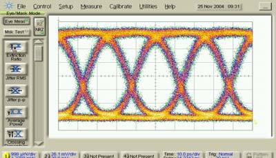


21 MECSE : "40G Overlay 10G DWDM Photonic Transmission Systems Using Advanced...", L.N. Binh RZ-ASK NRZ-ASK 0Km 1.0Km 2km 3km 4Km Figure 12 Samples of eye diagrams of ASK modulation formats SSMF length is a parameter.


22 MECSE : "40G Overlay 10G DWDM Photonic Transmission Systems Using Advanced...", L.N. Binh CS-RZ-ASK NRZ-DPSK 0 Km 1 Km 2 Km 3 Km 4 Km Figure 13 Samples of eye diagrams of phase difference NRZ-DPSK and CSRZ ASK modulation formats SSMF length is a parameter.


23 MECSE : "40G Overlay 10G DWDM Photonic Transmission Systems Using Advanced...", L.N. Binh RZ-DPSK CSRZ-DPSK 0 Km 1 Km 2 Km 3 Km 4 Km Figure 14 Samples of eye diagrams of phase difference modulation formats SSMF length is a parameter.
24 MECSE : "40G Overlay 10G DWDM Photonic Transmission Systems Using Advanced...", L.N. Binh 5 DISPERSION TOLERANCE OF DIFFERENT MODULATION FORMATS 40G sent via SMF first them amp and then 1.2nm filter to ensure no nonlinearities. Used "cheated clock" i.e. directly from PRBS generator to Error Analyser for non-dpsk fornats as we had to use a "LAB BUDDY" 45GHz Rx with in-built amp directly onto Error Analyser without an external electrical amplifier as it would distort the detected eye diagram. This means that the optical power is not sufficiently high to drive clock extractor. 5.1 NRZ-ASK 10-5 NRZ- ASK format 10-6 Error Probability km Received Power Level (dbm) Figure 15 BER versus receiver sensitivity (-10dB) for NRZ format transmission back to back (0km) and 1-4 km of SSMF.
25 MECSE : 5.2 NRZ DPSK "40G Overlay 10G DWDM Photonic Transmission Systems Using Advanced...", L.N. Binh km 10-6 Error Probability Received Power Level (dbm) Figure 16 BER versus receiver power obtained for NRZ DPSK format with back-to-back (0km) and 1-4 m SSMF. 5.3 RZ Format km Error Probability ,1,2 km 3km Received Power Level (dbm) Figure 17 BER versus Rx sensitivity (-10dB) modulation format RZ ASK
26 MECSE : 5.4 CS-RZ "40G Overlay 10G DWDM Photonic Transmission Systems Using Advanced...", L.N. Binh Error Probability km Received Power Level (dbm) Figure 18 BER versus Rx sensitivity (-10dB) modulation format CS_RZ ASK. Yellow dots are for back-toback. 5.5 RZ-DPSK Error Probability km Received Power Level (dbm) Figure 19 BER versus receiver sensitivity (-10dB) power obtained for RZ DPSK format with back-to-back (0km) and 1-4 m SSMF.
27 MECSE : 5.6 RZ-DPSK "40G Overlay 10G DWDM Photonic Transmission Systems Using Advanced...", L.N. Binh 10-5 Error Probability km Received Power Level (dbm) Figure 20 BER versus receiver sensitivity (-10dB) power obtained for CS-RZ DPSK format with back-to-back (0km) and 1-4 m SSMF.. Note the ~3-4dB improvement of the RZ type DPSK s over ASK formats.
28 MECSE : "40G Overlay 10G DWDM Photonic Transmission Systems Using Advanced...", L.N. Binh Modulation Format: Distance v Penalty Penalty (db) NRZ RZ CS RZ NRZ DPSK RZ DPSK CS RZ DPSK -2 1km 2km 3km 4km Distance (km) Figure 21 Power penalty as a function of the transmission distance for various modulation formats 6 40 GB/S TRANSMISSION: LONG HAUL TRANSMISSION 50 KM AND 320 KM OPTICAL TRANSMISSION EFFECTS ON MODULATION FORMATS 6.1 Transmission over 50 Km dispersion compensated span NEL-AWG 100G-0.5nm DCFM -850ps/nm SSMF Tx SHF5008 EDFA1 50 km EDFA2 NEL-AWG 100G-0.5nm AQ3105 SHF EA POWER METER CLK SHFEA4 4 Figure 22 Dispersion managed 50 km SSMF +DCFM transmission system set-up
29 MECSE : "40G Overlay 10G DWDM Photonic Transmission Systems Using Advanced...", L.N. Binh BER plot- CSRZ-DPSK 50 km SSMF+DCFM -850ps/nm lamda= nm 1e-005 1e-006 1e-007 BER 1e-008 1e-009 1e-010 1e-011 1e-012 1e PRx [dbm] Figure 23: Receiver sensitivity of the CSRZ-DPSK modulation format. Transmission distance= 50 km SSMF + Sumitomo DCFM (-850 source wavelength lamda 5 = nm CSRZ-DPSK transmission after 50 km SSMF and DCFM (-850 ps/nm at 1550 nm). 1e-005 BER - RZ-DPSK 50 km transmission + DCFM Sumitmo -850ps/nm 1e-006 1e-007 BER 1e-008 1e-009 1e-010 1e-011 1e-012 1e PRx [dbm] Figure 24 Optical transmission over 50 km of SSMF + DCFM (total dispersion -850 ps/nm); Modulation format = RZ DPSK, Eye diagram captured at dbm at the power meter (1:10 FC port). Note: full clock recovery used for sampling the EA 44E. Centre wavelength (lamda 5) = nm.
30 MECSE : "40G Overlay 10G DWDM Photonic Transmission Systems Using Advanced...", L.N. Binh BER RZ DPSK(blue)- CSRZ-DPSK(red) 50 km SSMF+DCFM -850ps/nm lamda1= nm 1e-005 1e-006 1e-007 BER 1e-008 1e-009 1e-010 1e-011 1e-012 1e PRx [dbm] Figure 25: RZ-DPSK (blue) and CSRZ-DPSK (red) modulation format transmission distance= 50 km SSMF + Sumitomo DCFM (-850 source wavelength (Lamda 1)= nm. MUX and DEMUX NEL-AWG circulant filter and spacing demultiplexing. Optical transmission over 50 km of SSMF + DCFM (total dispersion -850 ps/nm) Modulation format = CSRZ DPSK, Eye diagram captured at dbm at the power meter (1:10 FC port) BER: Lamda16( nm) transmission 50 km SSMF+DCFM(-850ps/nm) 1e-005 1e-006 1e-007 BER 1e-008 1e-009 1e-010 1e-011 1e-012 1e PRx [dbm] Figure 26 Optical transmission over dispersion managed 50 km of SSMF + DCFM (total dispersion -850 ps/nm); Modulation format = CSRZ DPSK (red) and RZ-DPSK (blue), Eye diagram captured. Note: full clock recovery used for sampling the EA 44E. Centre wavelength (Lamda 16) = nm
31 MECSE : 6.2 Transmission "40G over Overlay G Km SSMF DWDM dispersion Photonic Transmission compensated Systems multi-span Using 328 Advanced KM SSMF...", L.N. + DCF320 Binh transmission Tx SHF5008 NEL-AWG 100G-0.5nm EDFA1 SSMF 100 km EDFA2 DCF50 + DCF kmssmf NEL-AWG 100G-0.5nm AQ3105 SHF EA EDFA2 SSMF SSMF 2.2 km 100 km DCF90 + DCF90 POWER METER SSMF 100 km CLK SHFEA4 4 Figure 27 Optically amplified dispersion managed transmission: 328 KM SSMF DCF transmission with CSRZ-DPSK and RZ DPSK formats. BER - RZ-DPSK(r*) and CSRZ-DPSK(bo) 328 km SSMF+ 320DCF transmission 1e-005 1e-006 BER - RZ- CSRZ 1e-007 1e-008 1e-009 1e-010 1e-011 1e-012 1e-013 1e PRx -RZ -CSRZ Figure 28 Transmission system: dispersion management 328 kmssmf + DCM320 compensating fibers. Note: MUX is NEL AWG 0.5 nm 100 GHz Spacing and DEMUX is 1.2 nm OF (thin film structure) (see red curve) blue is for NEL-AWG+NEL-AWG (100 GHz spacing and 0.5 nm BW) as MUX and DEMUX 7 OPTICAL FILTER EFFECTS ON MODULATION FORMATS 7.1 Filters used in the demonstration (Telstra Labs): NEL AWG mux/demux filter 0.45 nm (3dB bandwidth) GHz spacing Piri AWG mux/demux filter 0.5 nm (3dB bandwidth) GHz spacing FBG 0.55 nm
32 MECSE : "40G Overlay AWG 10G 8 Channel DWDM Demux Photonic Transmission 0.35 nm Systems Using Advanced...", L.N. Binh JDS tunable filter 1.3 nm Santec 0.5 nm slow roll off. Notes: Pattern , gate by time (in Rx): 1ms; polarization has been optimally adjusted. Adjusting Variable Attenuator ANDO-AQ Operating at 40 Gbps with clock synchronized at GHz. At Rx, heater current: 15.5 ma ; heater Temp: 33.3 º C 7.2 PIRI AWG Mux/Demux Filter 0.45 nm NEL-AWG 100G-0.5nm NEL-AWG 100G-0.5nm AQ3105 SHF5003 Tx SHF5008 EDFA1 EDFA2 clk Lamda5 = nm 1:10 84EA SHF BPG44E POWER METER CLK Cheated CLK SHFEA4 4 Figure 29 Experimental set-up to measure the optical filtering on modulation formats Optical filters:one FILTER NEL AWG ONLY. 1e-005 BER plot 1e-006 1e-007 BER 1e-008 1e-009 1e-010 1e-011 1e-012 1e PRx [dbm] Figure 30 BER versus received optical power (at the power meter 1;10 coupler before Rx). Note: blue CSRZ-DPSK; red RZ DPSK; green NRZ ASK; yellow CSRZ- ASK; c RZ-ASK; Note bien: only one optical filter NEL AWG is used
33 MECSE : "40G Overlay 10G DWDM Photonic Transmission Systems Using Advanced...", L.N. Binh NEL-AWG NEL-AWG 100G-0.5nm 100G-0.5nm AQ3105 Tx SHF5008 EDFA1 EDFA2 SHF clk Lamda5 = nm 1:10 84EA SHF BPG44E POWER METER CLK Cheated CLK SHFEA4 4 Figure 31 Experimental set up OPTICAL FILTRER EFFECTS (TWO FILTERS NEL AWG +EDFA +NEL- AWG +EDFA) ON MODULATION FORMAT. Note: only CSRZ-DPSK and RZ-DPSK gives recorded BER, EDFA1 = 176 mw pump power saturation mode; EDFA2 = 132 mw pump power saturation mode 1e-005 BER plot 1e-006 1e-007 1e-008 BER 1e-009 1e-010 1e-011 1e-012 1e PRx [dbm] Figure 32 BER versus received optical power (at the power meter 1;10 coupler before Rx). Legends: blue CSRZ-DPSK (one NELAWG); red RZ DPSK(one NELAWG); green NRZ ASK(one NELAWG); yellow CSRZ- ASK (one NELAWG); c RZ-ASK(one NELAWG); Note: only one optical filter NEL AWG is used; Red o CSRZ DPSK TWO AWGs used; blue o RZ-DPSK TWO AWGs used 7.3 Testbed set up Figure 33 shows an example for one of the setup of the experiments.
34 MECSE : "40G Overlay 10G DWDM Photonic Transmission Systems Using Advanced...", L.N. Binh PM fibre NEL-AWG 100G-0.5nm DCFM -850ps/nm SSMF Tx SHF5003 EDFA1 50 km EDFA2 NEL-AWG 100G-0.5nm AQ3105 SHF EA POWER METER CLK SHFEA44 Figure Km SSMF transmission experimental set-up The details of the equipment are DPSK Optical Transmitter SHF 5003 Bit Pattern Generator model SHF BPG44E - SHF Communication Technologies DPSK Optical Receiver SHF 5008 Error Analyzer SHF EA 44 40G Clock Recovery Unit SHF 1120A Laser Source Anritsu. Max 8dBm Oscilloscope Tektronix. With 70GHz optical plug-in and Agilent. With 50GHz optical plug-in Spectrum Analyser Photonetics OSA. Filters: (i) NEL AWG Mux/Demmux 0.45nm bandwidth (ii) AWG JDS 8 channel Mux/Demux 0.35 nm (iii) JDS 1.2 nm (iv) Santec 0.5 nm slow roll-off. 7.4 Optical Spectra of Modulation Formats Centre wavelength of the light source is nm Spectrum of NRZ,RZ and CSRZ
35 MECSE : "40G Overlay 10G DWDM Photonic Transmission Systems Using Advanced...", L.N. Binh Optical Spectra of ASK Modulation Formats Power (dbm) Wavelength (nm) NRZ-ASK RZ-ASK CSRZ-ASK Figure 34 Optical spectra modulation formats amplitude shift keying of various formats Spectrum of NRZ-DPSK, RZ-DPSK and CSRZ-DPSK Optical Spectra of DPSK Modulation Formats CSRZ DPSK NRZ DPSK RZ DPSK Power (dbm) Wavelength (nm) Figure 35 Optical spectra modulation formats phase shift keying of various formats 7.5 Effects of Filter passband on system performance Effect of single filter CS-RZ at 40G through 1.2nm tunable and 100GHz AWG (0.5nm 3dB bandwidth):
36 MECSE : "40G Overlay 10G DWDM Photonic Transmission Systems Using Advanced...", L.N. Binh 10-5 Error Probability Received Power Level (dbm) Figure 36 Probability of error versus receiver sensitivity (dbm) for CS-RZ format blue dots for 1.2 nm thin film filter and yellow dots for 0.5 nm AWG filter (demux with 100 GHz spacing) The 100GHz AWG is obviously too narrow to pass the complete CS-RZ 40Gbit/s signal. However, 1.2nm (~150GHz) is far too wide for the standard ITU frequency grid Effects of double Filters 40G CS RZ DPSK muxed then demuxed via 2 NEL 100GHz AWG s cf 0ne AWG (3dB bandwidth is 0.5nm) + 1.2nm tunable filter- via attenuator only, no fiber. 2 AWG s obviously too narrow to pass 40G CS RZ DPSK sufficiently Error Probability AWG + 1.2nm AWG's Received Power Level (dbm)
37 MECSE : Figure 37 Probability "40G Overlay of error 10G versus DWDM receiver Photonic sensitivity Transmission (dbm) for Systems CS-RZ Using format Advanced blue dots...", for L.N. 1.2 Binh nm thin film filter and yellow dots for two 0.5 nm AWG filter (demuxed with 100 GHz spacing)at the mux and demux stages. 8 MUTUAL IMPACT OF ADJACENT 10G/40G CHANNELS IN OVERLAY TRANSMISSION Tx SHF5008 NEL-AWG 100G-0.5nm 328 KM SSMF + DCF320 transmission SSMF EDFA1 100 km EDFA2 DCF50 +DCF kmssmf NEL-AWG 100G-0.5nm AQ3105 Rx SHF5008 RF Amp PRx POWER METER CLK 6dB splitter EDFA2 DCF90 +DCF90 SHFEA44 SSMF SSMF 2.2 km 100 km SSMF 100 km Figure KM SSMF DCF Transmission with CSRZ-DPSK and RZ DPSK formats Notes: The length of SSMF is selected to be 328 km as it gives the best BER which can be achieved (theoretically, dispersion is nearly completely compensated) km SSMF + DCF for 320 km Tx: Impact of Adjacent 10G/40G Channels 320km transmission performance with a 10G NRZ ASK and a CS-RZ DPSK 40G channel to test adjacent and non-adjacent channel performance with a 100GHz AWG mux and a 1.2nm tunable filter at the input of the Rx. Significant penalty when adjacent 40G channel switched on due to the narrow width of the tunable filter. Non adjacent channel too far off to have any impact G@193.1 Error Probability G@ G@ G@ G@ Received Power Level (dbm)
38 MECSE : Figure G impact "40G Overlay on 10G 10G channel: DWDM Probability Photonic Transmission of error versus Systems receiver Using sensitivity Advanced (dbm)-...", effects L.N. Binh of 40 G with 10G (NRZ-ASK) channel simultaneously transmitted for NRZ ASK and CS-RZ DPSK formats blue dots for 1.2 nm thin film filter and dots for 0.5 nm AWG filter (demux with 100 GHz spacing). The set up of the transmission system with 320km SSMF and dispersion compensating module with 2 100GHz AWG s as muxes and Rx filter to measure the impact of adjacent CS-RZ DPSK 40G channel on 10G NRZ- ASK performance. No significant impact noted when 40G channel, adjacent or non-adjacent, is switched on. (Note: demo only as 40G channel would not actually perform well through such a narrow filtering arrangement) G@193.5 Error Probability G@ G@ G@ G@ Received Power Level (dbm) Figure km transmission 40 G impact on 10G channel: Probability of error versus receiver sensitivity (dbm)- effects of 40 G (CS_RZ DPSK) with 10G (NRZ-ASK) channel simultaneously transmitted for NRZ ASK and CS-RZ DPSK formats blue dots for 1.2 nm thin film filter and dots for 0.5 nm AWG filter (demux with 100 GHz spacing) Result shows that there is no appreciable impact on 10G signal of an adjacent 40G signal. For the case that two 100GHz AWG s are used as the mux and Rx filter for CS RZ DPSK transmission over 320km, we now measure the performance of the 40G stream transmitted simultaneously with adjacent and non-adjacent 10G channel. Note problem with using 2 AWG s at 40Gb/s as there is significant error floor. However we can see that 10G adjacent or non-adjacent creates no impact on 40G signal as expected. Small improvement with 40G channel on probably due to lower noise power contributed from EDFA.
39 MECSE : "40G Overlay 10G DWDM Photonic Transmission Systems Using Advanced...", L.N. Binh only Error Probability Received Power Level (dbm) Figure 41 Impact on 40 G with 10 G channel transmission 320 km transmission: Probability of error versus receiver sensitivity (dbm)- effects of 40 G (CS_RZ DPSK) with 10G (NRZ-ASK) channel simultaneously transmitted for NRZ ASK and CS-RZ DPSK formats blue dots for 1.2 nm thin film filter and dots for two 0.5 nm AWG filter (demux with 200 GHz spacing) 9 DISPERSION TOLERANCE AND SENSITIVITY OF VARIOUS MODULATION FORMATS EDFA 40 Gbps Tx PM Fibre SMF vary from 0-4 km Attn 1.2 nm filter Rx Elec Amp PRBS Cheated Clock Error Analyser Figure 42 Experimental set up to measure the dispersion tolerance of different modulation formats. Notes: 40Gbps Tx is SHF 5003 DPSK Transmitter which can generate both ASK and DPSK data In case of ASK, Lab Buddy Optical Receiver (45 GHz with built-in amplifier) is used In case of DPSK, SHF 5008 DPSK receiver is used (MZ 1 bit delay). Also, the Electrical Amp is utilized to drive the Error Analyser.
40 MECSE : JDS 1.2 nm "40G filter Overlay was utilized 10G DWDM after Photonic EDFA to Transmission decrease the ASE Systems noise Using level. Advanced...", L.N. Binh Power launched into SMF (right after the Tx) is low, hence nonlinearities do not have any impact. NRZ-ASK RZ-ASK CSRZ-ASK NRZ-DPSK RZ-DPSK CSRZ-DPSK Launched Power (dbm) Cheated Clock i.e. without using the Clock Recovery Unit, the Error Analyser directly using clock pulse of the PRBS. Laser Source: nm Pulse pattern of PRBS is 2^ RZ-ASK 1e-005 1e-006 BER plot 0 km 1 km 2 km 3 km 1e-007 BER 1e-008 1e-009 1e-010 1e-011 1e-012 1e PRx [dbm] Figure 43 BER as a function of receiver sensitivity with SSMF length as a parameter. Modulation format: RZ - ASK. measured BER and Received Power % note: received power = reading power (at the power meter) + 10 db (coupler 1:10) (Insertion loss)
41 MECSE : 9.2 CSRZ-ASK "40G Overlay 10G DWDM Photonic Transmission Systems Using Advanced...", L.N. Binh 1e-005 1e-006 1e-007 Dispersion Tolerance - CSRZ-ASK 1 km 0 km 2 km 3 km 4 km 1e-008 BER 1e-009 1e-010 1e-011 1e-012 1e PRx [dbm] Figure 44 BER as a function of receiver sensitivity with SSMF length as a parameter. Modulation format: carrier-suppressed RZ. 9.3 NRZ-ASK 1e-005 1e-006 1e-007 Dispersion Tolerance - NRZ-ASK 0 km 1 km 2 km 3 km 4 km 1e-008 BER 1e-009 1e-010 1e-011 1e-012 1e PRx [dbm] Figure 45 BER as a function of receiver sensitivity with SSMF length as a parameter. Modulation format: RZ- ASK.
42 MECSE : 9.4 RZ-DPSK "40G Overlay 10G DWDM Photonic Transmission Systems Using Advanced...", L.N. Binh 1e-005 1e-006 Dispersion Tolerance - RZ-DPSK 0 km 1 km 2 km 3 km 1e-007 1e-008 BER 1e-009 1e-010 1e-011 1e-012 1e PRx [dbm] Figure 46 BER as a function of receiver sensitivity with SSMF length as a parameter. Modulation format: RZ- DPSK. 9.5 CSRZ- DPSK 1e-005 1e-006 Dispersion Tolerance - CSRZ-DPSK 0 km 1 km 2 km 3 km 1e-007 1e-008 BER 1e-009 1e-010 1e-011 1e-012 1e PRx [dbm] Figure 47 BER as a function of receiver sensitivity with SSMF length as a parameter. Modulation format: carrier-suppressed RZ-DPSK. Note: NRZ DPSK does not work probably and drifting only work on PRBS pattern of 2^ FILTER EFFECTS BACK TO BACK JUST WITH NEL AWG AND 2 NEL AWG CASCADED WITHOUT SPLITTER 10.1 Single NELAWG filter:
43 MECSE : "40G Overlay 10G DWDM Photonic NEL-AWG Transmission Systems Using Advanced...", L.N. Binh 100G-0.5nm EDFA PM Fibre Attn 40 Gbps Tx Rx Elec Amp PRBS Cheated Clock Error Analyser Figure 48 Experimental set up to measure the optical filtering effects on different modulation formats 10.2 Cascaded NELAWG filters NEL-AWG NEL-AWG 100G-0.5nm 100G-0.5nm EDFA1 EDFA2 Attn PM Fibre 40 Gbps Tx Rx PRBS Cheated Clock Elec Amp Error Analyser Figure 49 Experimental set up to measure the optical filtering effects on different modulation formats using two filters. Notes: In this experiment, the 6 db splitter was not utilized, which is very significant for later on to understand that the Received Power with 6dB splitter will be higher ASK 1e-005 1e-006 Filter Effects - Single NELAWG and 2 NELAWG cascaded CSRZ-SingleNEL RZ- SingleNEL CSRZ - 2NELcascaded RZ - 2NELcascaded 1e-007 BER 1e-008 1e-009 1e-010 1e-011 1e-012 1e PRx [dbm] Figure 50 Effects of filtering - BER as a function of receiver sensitivity with modulation formats as a parameter: CSRZ ASK, RZ-ASK and CSRZ-ASK
44 MECSE : 10.4 DPSK "40G Overlay 10G DWDM Photonic Transmission Systems Using Advanced...", L.N. Binh 1e-005 1e-006 Filter Effects - DPSK - Single NELAWG and 2 NELAWG cascaded CSRZ-DPSK - SingleNEL RZ-DPSK - SingleNEL CSRZ-DPSK - 2NELCascaded RZ-DPSK - 2NELCascaded 1e-007 1e-008 BER 1e-009 1e-010 1e-011 1e-012 1e PRx [dbm] Figure 51 Effects of filtering - BER as a function of receiver sensitivity with modulation format of phase difference: RZ, NRZ and CSRZ. 11 NON-LINEAR EFFECTS (DCF+50KMSSMF; 50KM SSMF + DCF; 234KM SMF+DCF FOR 230 KM) 11.1 DCF 50km SMF transmission Tx SHF5003 PM fibre EDFA1 NEL-AWG 100G-0.5nm EDFA2 Attn DCFM -850ps/nm SSMF 50 km EDFA3 NEL-AWG 100G-0.5nm AQ3105 Rx SHF5008 BRPS RF Amp Ptx PRx 6dB splitter POWER METER CLK SHFEA44 Figure km DCF +SMF Transmission system set-up Photonic components driving conditions Laser source: tunable laser set at nm for centred wavelength (lamda 5) and nm for lamda nm for lamda 16. NEL-AWG = frequency spacing 100G 3 db BW of 0.5 nm. Circulating property so spectrum would appear cyclic (note the spectrum) - note of the channel input and out put e.g input at port 5 of Lamda 5 then output at port 8. Input Lamda 1 at port 1 then output at port 8 (Lamda 1). Tx can be set at CSRZ-DPSK or RZ- DPSK Clock recovery using 6 db splitter
45 MECSE : Tuning of "40G MZ Overlay phase decoder 10G DWDM at the Photonic Rx is necessary Transmission when lamda Systems channels Using are Advanced changed...", L.N. Binh EDFA 1 driven at 178 mw pump power (saturation mode). EDFA2 driven at 197 mw (saturation mode). Attenuator is used to vary the optical power input at the receiver. Notes: DCF has lower nonlinear power threshold. Hence, it is expected that nonlinearities starts their effects at lower launched power compared to 50km SMF-DCF Receiver Sensitivity Notes: Tune the wavelength of the laser source : lamda1 = nm, lamda5 = nm and lamda 16 = nm (according to ITU grid standard). This is to show that different channels through the Mux/Demux with different dispersiioncharacteristics- it is important to do mobbing for achievement of complete dispersion compensation. Mod formats implemented are: RZ-DPSK and CSRZ-DPSK.. Power launched into the Sumitomo DCFM was measured to be 7.1 dbm. It is expected that 40GHz clock Recovery unit was utilized. Use two NELAWG Mux/Demux filters 100GHz spacing 3dB bandwidth 0.45 nm - alike the currently deployed real 100 GHz spacing system. DCF module for dispersion compensation is: Sumitomo DCFM (-850 ps/nm@ 1550nm). Power used in the BER plot is the reading power at the power meter. The received power can easily be calculated by: Received Power = Reading power + 10dB (1:10 coupler) 0.7 (insertion loss of the coupler) Compare BER with different Tx wavelengths (showing the importance of mobbing/compensating dispersion on different channels in the system.) RZ-DPSK BER of RZ-DPSK System: DCFM + 50 km SSMF with various wavelengths 1e-005 λ 1 = nm λ 5 = nm λ 1e = nm 1e-007 BER 1e-008 1e-009 1e-010 1e-011 1e-012 1e PRx [dbm] Figure 53 transmission over 50 km SSMF: BER versus Rx sensitivity. Modulation format: RZ-DPSK.
46 MECSE : CSRZ-DPSK "40G Overlay 10G DWDM Photonic Transmission Systems Using Advanced...", L.N. Binh BER of CSRZ-DPSK System: DCFM + 50 km SSMF with various wavelengths 1e-005 λ 1 = nm λ 5 = nm λ 1e = nm 1e-007 BER 1e-008 1e-009 1e-010 1e-011 1e-012 1e PRx [dbm] Figure 54 transmission over 50 km SSMF: BER versus Rx sensitivity. Modulation format: CSRZ-DPSK At interested λ = nm, compare BER between CSRZ- DPSK and RZ-DPSK on the system of DCF- 50 km SMF 1e-005 BER of System: DCFM + 50 km SSMF at λ 5 = nm CSRZ-DPSK RZ-DPSK 1e-006 1e-007 BER 1e-008 1e-009 1e-010 1e-011 1e-012 1e PRx [dbm] Figure 55 transmission over 50 km SSMF: BER versus Rx sensitivity. Modulation format: CSRZ and RZ- DPSK.
47 MECSE : CSRZ-DPSK "40G Overlay 10G DWDM Photonic Transmission Systems Using Advanced...", L.N. Binh 1e-005 1e-006 CSRZ DPSK -- System: DCFM + 50km SSMF 2.8dBm 7.6dBm 11dBm 13dBm 0dBm 1e-007 BER 1e-008 1e-009 1e-010 1e-011 1e-012 1e PRx [dbm] Figure 56 Transmission over 50 km SSMF: BER versus Rx sensitivity with total launched power as a parameter. Modulation format: CSRZ-DPSK RZ-DPSK e-005 1e-006 RZ DPSK -- System: DCFM + 50km SSMF 2.8dBm 7.6dBm 11dBm 13dBm 0dBm BER 1e-007 1e-008 1e-009 1e-010 1e-011 1e-012 1e PRx [dbm] Figure 57 transmission over 50 km SSMF: BER versus Rx sensitivity with total launched power as a parameter. Modulation format: RZ-DPSK
48 MECSE : CSRZ-ASK "40G Overlay 10G DWDM Photonic Transmission Systems Using Advanced...", L.N. Binh e-005 CSRZ OOK -- System: DCFM + 50km SSMF 2.8dBm 7.6dBm 11dBm 1e-006 BER 1e-007 1e-008 1e-009 1e-010 1e-011 1e-012 1e PRx [dbm] Figure 58 transmission over 50 km SSMF: BER versus Rx sensitivity with total launched power as a parameter. Modulation format: CSRZ-ASK RZ-ASK e-005 RZ OOK -- System: DCFM + 50km SSMF 2.8dBm 7.6dBm 11dBm 13dBm 1e-006 BER 1e-007 1e-008 1e-009 1e-010 1e-011 1e-012 1e PRx [dbm] Figure 59 transmission over 50 km SSMF: BER versus Rx sensitivity with total launched power as a parameter. Modulation format: RZ-ASK km SMF + DCF Transmission Nonlinear effects Investigation by varying the launched power
49 MECSE : "40G Overlay 10G DWDM Photonic Transmission Systems Using Advanced...", L.N. Binh Tx SHF5003 PM fibre EDFA1 NEL-AWG 100G-0.5nm EDFA2 SSMF Attn 50 km DCFM -850ps/nm EDFA3 NEL-AWG 100G-0.5nm AQ3105 Rx SHF5008 BRPS RF Amp Ptx PRx 6dB splitter POWER METER CLK SHFEA44 Figure 60 Transmission performance of dispersion managed fibres: 50km SMF + DCF CSRZ-DPSK 1e-005 1e-006 CSRZ DPSK -- System: 50km SSMF + DCFM 2.8dBm 7.6dBm 11dBm 15.1dBm 16dBm 1e-007 BER 1e-008 1e-009 1e-010 1e-011 1e-012 1e PRx [dbm] Figure 61 Transmission over 50 km SSMF dispersion management: BER versus Rx sensitivity with total launched power as a parameter. Modulation format: CSRZ-DPSK
50 MECSE : RZ-DPSK "40G Overlay 10G DWDM Photonic Transmission Systems Using Advanced...", L.N. Binh 1e-005 1e-006 RZ DPSK 2.8dBm back2back 1e-007 BER 1e-008 1e-009 1e-010 1e-011 1e-012 1e PRx [dbm] Figure 62 Transmission over 50 km SSMF: BER versus Rx sensitivity with total launched power as a parameter. Modulation format: RZ-DPSK 12 * 234KM SMF AND DCF FOR 230 KM TRANSMISSION Tx SHF5003 PM fibre NEL-AWG 100G-0.5nm EDFA2 Attn 103km SMF EDFA3 DCF-90 EDFA1 PTx BRPS 50km SMF 31 km SMF EDFA6 DCF-90 EDFA5 100 km SMF EDFA4 EDFA7 NEL-AWG 100G-0.5nm AQ3105 Rx SHF5008 RF Amp PRx 6dB splitter POWER METER CLK SHFEA44 Notes: Figure 63 - Experiment setup: CSRZ DPSK 230km transmission, 234km SMF + DCF for 230km
51 MECSE : Mobbing "40G up the Overlay dispersion 10G to DWDM have the Photonic best BER Transmission - λ10 = Systems Using nm compared Advanced to λ5=...", L.N Binhnm. Hence, laser source is tuned to λ10. The nonlinear effect is explored by varying the optical power lauched into the SMF from 0dBm to 15dBm. The power lauched into the DCF is kept unchanged at 0dBm (nonlinearities are generated in SMF not DCF). 1e-005 1e-006 1e-007 CSRZ DPSK 230km Transmission 0dBm 3dBm 6dBm 9dBm 12dBm 15dBm BER 1e-008 1e-009 1e-010 1e-011 1e-012 1e PRx [dbm] Figure 64 Figure 65 transmission over 234 km SSMF: BER versus Rx sensitivity with total launched power as a parameter. Modulation format: CSRZ-DPSK Optical filter JDS 0.35 nm 100G/8channel Mux/Demux filter Filter Effects with the same set up for comparison. NEL-AWG 100G-0.5nm Tx SHF5003 PM fibre EDFA Aq3105 Attn OOK or DPSK Rx 84EA PRx POWER METER CLK SHFEA44 Figure 66 Measurement set-up of BER and Rx sensitivity due to filter effects
52 MECSE : CSRZ-DPSK "40G Overlay Filter Effects 10G DWDM Photonic Transmission Systems Using Advanced...", L.N. Binh BER plot for Filter Effects -- CSRZ-DPSK 1e-005 1e-006 Santec 0.6nm JDS 0.35 nm JDS 1.2 nm NELAWG 0.45nm 1e-007 BER 1e-008 1e-009 1e-010 1e-011 1e-012 1e PRx [dbm] Figure 67 Optical filtering effects: BER versus Rx sensitivity format CS_RZ DPSK Spectra of CSRZ-DPSK Filtered Signals Power (dbm) Wavelength (nm) Jds 0.3 nm Jds 1.2 nm NEL AWG Santec 0.6 nm Figure 68 Optical Spectra of filtered lightwave signals
53 MECSE : RZ-DPSK "40G Filter Overlay Effects 10G DWDM Photonic Transmission Systems Using Advanced...", L.N. Binh 1e-005 1e-006 BER plot for Filter Effects -- RZ-DPSK Santec 0.6nm JDS 0.35 nm JDS 1.2 nm NELAWG 0.45 nm 1e-007 BER 1e-008 1e-009 1e-010 1e-011 1e-012 1e PRx [dbm] Figure 69 BER versus Rx sensitivity format RZ DPSK Spectra of RZ-DPSK Filtered Signals 0-10 Power (dbm) Wavelength (nm) Jds 0.35 nm Jds 1.2 nm NELAWG Santec 0.6 nm Figure 70 Optical Spectra of filtered lightwave signals- format RZ-DPSK
54 MECSE : RZ-ASK "40G Filter Overlay Effects 10G DWDM Photonic Transmission Systems Using Advanced...", L.N. Binh 1e-005 1e-006 BER plot for Filter Effects -- RZ-ASK Santec 0.6nm JDS 0.35 nm JDS 1.2 nm NELAWG 0.45 nm 1e-007 BER 1e-008 1e-009 1e-010 1e-011 1e-012 1e PRx [dbm] Figure 71 BER versus Rx sensitivity format RZ ASK Spectra RZ-ASK Filtered Signals Power (dbm) Wavelength (nm) Jds 0.35 nm Jds 1.2 nm NELAWG Santec 0.6 nm Figure 72 Optical spectra of optically filtered format RZ-ASK CSRZ-DPSK nm JDS Mux/Demux filter and detuning the wavelength of laser source to ensure that such a narrow filter is still be applicable to 40G/s CSRZ-DPSK signal. 13 CONCLUDING REMARKS AND FURTHER WORKS The demonstration of the transmission of 40 Gb/s channels over 10 Gb/s DWDM optically amplified fibre communications systems has been proven that: It is possible to transmit 40Gb/s channels when the data sequence is encoded with amplitude and phase difference modulation. The formats CSRZ seems to offer the best performance and more dispersion tolerable than other reported formats. The impacts of optical filters employed in 10 Gb/s and 100 GHz channel spacing DWDM optically amplified system are minimal and should create no more than 2 db penalty. This can be easily compensated with optical amplification of either EDFA or Raman distributed amplification.


55 MECSE : The nonlinear "40G Overlay SPM effects 10G are DWDM also Photonic investigated Transmission and it proven Systems that Using the 40 Advanced Gb/s does...", not L.N. suffer, Binh especially when the CSRZ format is used. Our next stage of investigation is to demonstrate the transmission of 40 Gb/s over a commercial 10 Gb/s DWDM optically amplified fibre transmission system, the Siemens TranXpress Multiwavelength Transport System as shown in Figure 73. A polarization emulator will be inserted in the fibre transmission path to simulate the real PMD effects in installed transmission fibres. Once this demonstration is proven feasible we would arrange for permission to transmit 40 Gb/s channels over installed long haul transmission systems, e.g. Melbourne Sydney or Adelaide to Perth optical transmission link. Figure 73 The Siemens TranXpress Multiwavelength Transport System
40Gb/s Optical Transmission System Testbed
 The University of Kansas Technical Report 40Gb/s Optical Transmission System Testbed Ron Hui, Sen Zhang, Ashvini Ganesh, Chris Allen and Ken Demarest ITTC-FY2004-TR-22738-01 January 2004 Sponsor: Sprint
Department of Electrical and Computer Systems Engineering
 Department of Electrical and Computer Systems Engineering Technical Report MECSE-4-2005 DWDM Optically Amplified Transmission Systems - SIMULINK Models and Test-Bed: Part III DPSK L.N. Binh and Y.L.Cheung
Department of Electrical and Computer Systems Engineering
 Department of Electrical and Computer Systems Engineering Technical Report MECSE-5-2005 SIMULINK Models for Advanced Optical Communications: Part IV- DQPSK Modulation Format L.N. Binh and B. Laville SIMULINK
Department of Electrical and Computer Systems Engineering
 Department of Electrical and Computer Systems Engineering Technical Report MECSE-3-2005 DWDM Advanced Optical Communication Simulink Models: Part I Optical Spectra L.N Binh and Y.L. Cheung DWDM ADVANCED
Performance Limitations of WDM Optical Transmission System Due to Cross-Phase Modulation in Presence of Chromatic Dispersion
 Performance Limitations of WDM Optical Transmission System Due to Cross-Phase Modulation in Presence of Chromatic Dispersion M. A. Khayer Azad and M. S. Islam Institute of Information and Communication
A Technique to improve the Spectral efficiency by Phase shift keying modulation technique at 40 Gb/s in DWDM optical systems.
 A Technique to improve the Spectral efficiency by Phase shift keying modulation technique at 40 Gb/s in DWDM optical systems. A.V Ramprasad and M.Meenakshi Reserach scholar and Assistant professor, Department
SHF Communication Technologies AG
 SHF Communication Technologies AG Wilhelm-von-Siemens-Str. 23 Aufgang D 12277 Berlin Marienfelde Germany Phone ++49 30 / 772 05 10 Fax ++49 30 / 753 10 78 E-Mail: sales@shf.biz Web: http://www.shf.biz
Comparative Analysis Of Different Dispersion Compensation Techniques On 40 Gbps Dwdm System
 INTERNATIONAL JOURNAL OF TECHNOLOGY ENHANCEMENTS AND EMERGING ENGINEERING RESEARCH, VOL 3, ISSUE 06 34 Comparative Analysis Of Different Dispersion Compensation Techniques On 40 Gbps Dwdm System Meenakshi,
Dr. Monir Hossen ECE, KUET
 Dr. Monir Hossen ECE, KUET 1 Outlines of the Class Principles of WDM DWDM, CWDM, Bidirectional WDM Components of WDM AWG, filter Problems with WDM Four-wave mixing Stimulated Brillouin scattering WDM Network
40Gb/s & 100Gb/s Transport in the WAN Dr. Olga Vassilieva Fujitsu Laboratories of America, Inc. Richardson, Texas
 40Gb/s & 100Gb/s Transport in the WAN Dr. Olga Vassilieva Fujitsu Laboratories of America, Inc. Richardson, Texas All Rights Reserved, 2007 Fujitsu Laboratories of America, Inc. Outline Introduction Challenges
Design of Ultra High Capacity DWDM System with Different Modulation Formats
 Design of Ultra High Capacity DWDM System with Different Modulation Formats A. Nandhini 1, K. Gokulakrishnan 2 1 PG Scholar, Department of Electronics & Communication Engineering, Regional Center, Anna
CHAPTER 3 PERFORMANCE OF MODULATION FORMATS ON DWDM OPTICAL SYSTEMS
 67 CHAPTER 3 PERFORMANCE OF MODULATION FORMATS ON DWDM OPTICAL SYSTEMS 3.1 INTRODUCTION The need for higher transmission rate in Dense Wavelength Division optical systems necessitates the selection of
SUBMARINE SYSTEM UPGRADES WITH 25 GHZ CHANNEL SPACING USING DRZ AND RZ-DPSK MODULATION FORMATS
 SUBMARINE SYSTEM UPGRADES WITH 25 GHZ CHANNEL SPACING USING DRZ AND RZ-DPSK MODULATION FORMATS Jiping Wen, Chunmei Yu, Tiegang Zhou, Xiaoyan Fan, Liping Ma (Huawei Marine Networks Co Ltd) Email:
Optical Fiber Technology
 Optical Fiber Technology 18 (2012) 29 33 Contents lists available at SciVerse ScienceDirect Optical Fiber Technology www.elsevier.com/locate/yofte A novel WDM passive optical network architecture supporting
40Gb/s Coherent DP-PSK for Submarine Applications
 4Gb/s Coherent DP-PSK for Submarine Applications Jamie Gaudette, Elizabeth Rivera Hartling, Mark Hinds, John Sitch, Robert Hadaway Email: Nortel, 3 Carling Ave., Ottawa, ON, Canada
Spectrally Compact Optical Subcarrier Multiplexing with 42.6 Gbit/s AM-PSK Payload and 2.5Gbit/s NRZ Labels
 Spectrally Compact Optical Subcarrier Multiplexing with 42.6 Gbit/s AM-PSK Payload and 2.5Gbit/s NRZ Labels A.K. Mishra (1), A.D. Ellis (1), D. Cotter (1),F. Smyth (2), E. Connolly (2), L.P. Barry (2)
UNREPEATERED SYSTEMS: STATE OF THE ART
 UNREPEATERED SYSTEMS: STATE OF THE ART Hans Bissessur, Isabelle Brylski, Dominique Mongardien (Alcatel-Lucent Submarine Networks), Philippe Bousselet (Alcatel-Lucent Bell Labs) Email: < hans.bissessur@alcatel-lucent.com
All-Optical Signal Processing and Optical Regeneration
 1/36 All-Optical Signal Processing and Optical Regeneration Govind P. Agrawal Institute of Optics University of Rochester Rochester, NY 14627 c 2007 G. P. Agrawal Outline Introduction Major Nonlinear Effects
Performance Analysis Of Hybrid Optical OFDM System With High Order Dispersion Compensation
 Performance Analysis Of Hybrid Optical OFDM System With High Order Dispersion Compensation Manpreet Singh Student, University College of Engineering, Punjabi University, Patiala, India. Abstract Orthogonal
FWM Suppression in WDM Systems Using Advanced Modulation Formats
 FWM Suppression in WDM Systems Using Advanced Modulation Formats M.M. Ibrahim (eng.mohamed.ibrahim@gmail.com) and Moustafa H. Aly (drmosaly@gmail.com) OSA Member Arab Academy for Science, Technology and
π code 0 Changchun,130000,China Key Laboratory of National Defense.Changchun,130000,China Keywords:DPSK; CSRZ; atmospheric channel
 4th International Conference on Computer, Mechatronics, Control and Electronic Engineering (ICCMCEE 2015) Differential phase shift keying in the research on the effects of type pattern of space optical
Fiber-Optic Communication Systems
 Fiber-Optic Communication Systems Second Edition GOVIND P. AGRAWAL The Institute of Optics University of Rochester Rochester, NY A WILEY-iNTERSCIENCE PUBLICATION JOHN WILEY & SONS, INC. NEW YORK / CHICHESTER
Current Trends in Unrepeatered Systems
 Current Trends in Unrepeatered Systems Wayne Pelouch (Xtera, Inc.) Email: wayne.pelouch@xtera.com Xtera, Inc. 500 W. Bethany Drive, suite 100, Allen, TX 75013, USA. Abstract: The current trends in unrepeatered
Dynamic gain-tilt compensation using electronic variable optical attenuators and a thin film filter spectral tilt monitor
 Dynamic gain-tilt compensation using electronic variable optical attenuators and a thin film filter spectral tilt monitor P. S. Chan, C. Y. Chow, and H. K. Tsang Department of Electronic Engineering, The
Chirped Bragg Grating Dispersion Compensation in Dense Wavelength Division Multiplexing Optical Long-Haul Networks
 363 Chirped Bragg Grating Dispersion Compensation in Dense Wavelength Division Multiplexing Optical Long-Haul Networks CHAOUI Fahd 3, HAJAJI Anas 1, AGHZOUT Otman 2,4, CHAKKOUR Mounia 3, EL YAKHLOUFI Mounir
Photonics (OPTI 510R 2017) - Final exam. (May 8, 10:30am-12:30pm, R307)
 - Final exam. (May 8, 10:30am-12:30pm, R307)") Photonics (OPTI 510R 2017) - Final exam (May 8, 10:30am-12:30pm, R307) Problem 1: (30pts) You are tasked with building a high speed fiber communication link between San Francisco and Tokyo (Japan) which
Photonics (OPTI 510R 2017) - Final exam (May 8, 10:30am-12:30pm, R307) Problem 1: (30pts) You are tasked with building a high speed fiber communication link between San Francisco and Tokyo (Japan) which
An Amplified WDM-PON Using Broadband Light Source Seeded Optical Sources and a Novel Bidirectional Reach Extender
 Journal of the Optical Society of Korea Vol. 15, No. 3, September 2011, pp. 222-226 DOI: http://dx.doi.org/10.3807/josk.2011.15.3.222 An Amplified WDM-PON Using Broadband Light Source Seeded Optical Sources
Department of Electrical and Computer Systems Engineering
 Department of Electrical and Computer Systems Engineering Technical Report MECSE-18-2005 DWDM ADVANCED OPTICAL COMMUNICATION - Part V: Long and DPSK Simulink Modeling and Experimental Demonstration Test-Beds
Spectral-Efficient 100G Parallel PHY in Metro/regional Networks
 Spectral-Efficient 100G Parallel PHY in Metro/regional Networks IEEE 802.3 HSSG January 2007 Winston I. Way wway@opvista.com OUTLINE Why spectral efficient DWDM for 100G? DWDM spectral efficiency advancement
Performance Analysis of Designing a Hybrid Optical Amplifier (HOA) for 32 DWDM Channels in L-band by using EDFA and Raman Amplifier
 for 32 DWDM Channels in L-band by using EDFA and Raman Amplifier") Performance Analysis of Designing a Hybrid Optical Amplifier (HOA) for 32 DWDM Channels in L-band by using EDFA and Raman Amplifier Aied K. Mohammed, PhD Department of Electrical Engineering, University
Performance Analysis of Designing a Hybrid Optical Amplifier (HOA) for 32 DWDM Channels in L-band by using EDFA and Raman Amplifier Aied K. Mohammed, PhD Department of Electrical Engineering, University
Digital Optical. Communications. Le Nguyen Binh. CRC Press Taylor &. Francis Group. Boca Raton London New York
 Digital Optical Communications Le Nguyen Binh CRC Press Taylor &. Francis Group Boca Raton London New York CRC Press is an imprint of the Taylor & Francis Group, an informa business Contents Preface Acknowledgments
Agilent 83430A Lightwave Digital Source Product Overview
 Agilent Lightwave Digital Source Product Overview SDH/SONET Compliant DFB laser source for digital, WDM, and analog test up to 2.5 Gb/s 52 Mb/s STM-0/OC-1 155 Mb/s STM-1/OC-3 622 Mb/s STM-4/OC-12 2488
SHF Communication Technologies AG
 SHF Communication Technologies AG Wilhelm-von-Siemens-Str. 23 Aufgang D 12277 Berlin Marienfelde Germany Phone ++49 30 / 772 05 10 Fax ++49 30 / 753 10 78 E-Mail: sales@shf.biz Web: http://www.shf.biz
Performance Analysis of Dwdm System With Different Modulation Techique And Photodiode
 The International Journal Of Engineering And Science (IJES) Volume 2 Issue 7 Pages 07-11 2013 ISSN(e): 2319 1813 ISSN(p): 2319 1805 Performance Analysis of Dwdm System With Different Modulation Techique
Colorless Amplified WDM-PON Employing Broadband Light Source Seeded Optical Sources and Channel-by-Channel Dispersion Compensators for >100 km Reach
 Journal of the Optical Society of Korea Vol. 18, No. 5, October 014, pp. 46-441 ISSN: 16-4776(Print) / ISSN: 09-6885(Online) DOI: http://dx.doi.org/10.807/josk.014.18.5.46 Colorless Amplified WDM-PON Employing
A WDM passive optical network enabling multicasting with color-free ONUs
 A WDM passive optical network enabling multicasting with color-free ONUs Yue Tian, Qingjiang Chang, and Yikai Su * State Key Laboratory of Advanced Optical Communication Systems and Networks, Department
SIMULATIVE INVESTIGATION OF SINGLE-TONE ROF SYSTEM USING VARIOUS DUOBINARY MODULATION FORMATS
 SIMULATIVE INVESTIGATION OF SINGLE-TONE ROF SYSTEM USING VARIOUS DUOBINARY MODULATION FORMATS Namita Kathpal 1 and Amit Kumar Garg 2 1,2 Department of Electronics & Communication Engineering, Deenbandhu
Wavelength Interleaving Based Dispersion Tolerant RoF System with Double Sideband Carrier Suppression
 Wavelength Interleaving Based Dispersion Tolerant RoF System with Double Sideband Carrier Suppression Hilal Ahmad Sheikh 1, Anurag Sharma 2 1 (Dept. of Electronics & Communication, CTITR, Jalandhar, India)
Phase Modulator for Higher Order Dispersion Compensation in Optical OFDM System
 Phase Modulator for Higher Order Dispersion Compensation in Optical OFDM System Manpreet Singh 1, Karamjit Kaur 2 Student, University College of Engineering, Punjabi University, Patiala, India 1. Assistant
Performance Comparison of Pre-, Post-, and Symmetrical Dispersion Compensation for 96 x 40 Gb/s DWDM System using DCF
 Performance Comparison of Pre-, Post-, and Symmetrical Dispersion Compensation for 96 x 40 Gb/s DWDM System using Sabina #1, Manpreet Kaur *2 # M.Tech(Scholar) & Department of Electronics & Communication
Performance Analysis of WDM RoF-EPON Link with and without DCF and FBG
 Optics and Photonics Journal, 2013, 3, 163-168 http://dx.doi.org/10.4236/opj.2013.32027 Published Online June 2013 (http://www.scirp.org/journal/opj) Performance Analysis of WDM RoF-EPON Link with and
Temporal phase mask encrypted optical steganography carried by amplified spontaneous emission noise
 Temporal phase mask encrypted optical steganography carried by amplified spontaneous emission noise Ben Wu, * Zhenxing Wang, Bhavin J. Shastri, Matthew P. Chang, Nicholas A. Frost, and Paul R. Prucnal
Prabhjeet Singh a, Narwant Singh b, Amandeep Singh c
 ISSN : 2250-3021 Investigation of DWDM System for Different Modulation Formats Prabhjeet Singh a, Narwant Singh b, Amandeep Singh c a B.G.I.E.T. Sangrur, India b G.N.D.E.C. Ludhiana, India c R.I.E.T, Ropar,
Performance of A Multicast DWDM Network Applied to the Yemen Universities Network using Quality Check Algorithm
 Performance of A Multicast DWDM Network Applied to the Yemen Universities Network using Quality Check Algorithm Khaled O. Basulaim, Samah Ali Al-Azani Dept. of Information Technology Faculty of Engineering,
UNREPEATERED SYSTEMS: STATE OF THE ART CAPABILITY
 UNREPEATERED SYSTEMS: STATE OF THE ART CAPABILITY Nicolas Tranvouez, Eric Brandon, Marc Fullenbaum, Philippe Bousselet, Isabelle Brylski Nicolas.tranvouez@alcaltel.lucent.fr Alcatel-Lucent, Centre de Villarceaux,
11.1 Gbit/s Pluggable Small Form Factor DWDM Optical Transceiver Module
 INFORMATION & COMMUNICATIONS 11.1 Gbit/s Pluggable Small Form Factor DWDM Transceiver Module Yoji SHIMADA*, Shingo INOUE, Shimako ANZAI, Hiroshi KAWAMURA, Shogo AMARI and Kenji OTOBE We have developed
Emerging Subsea Networks
 EVALUATION OF NONLINEAR IMPAIRMENT FROM NARROW- BAND UNPOLARIZED IDLERS IN COHERENT TRANSMISSION ON DISPERSION-MANAGED SUBMARINE CABLE SYSTEMS Masashi Binkai, Keisuke Matsuda, Tsuyoshi Yoshida, Naoki Suzuki,
Simulation of Pre & Post Compensation Techniques for 16 Channels DWDM Optical Network using CSRZ & DRZ Formats
 Simulation of Pre & Post Compensation Techniques for 16 Channels DWDM Optical Network using CSRZ & DRZ Formats Richa Arya 1, Malti Rani 2 1 M. Tech, Computer Science Department, Punjab Technical University,
Implementation and analysis of 2 Tbps MDRZ DWDM system at ultra narrow channel spacing
 Implementation and analysis of 2 Tbps MDRZ DWDM system at ultra narrow channel spacing 1 Ragini Sharma, 2 Kamaldeep Kaur 1 Student, 2 Assistant Professor Department of Electrical Engineering BBSBEC, Fatehgarh
Performance Analysis Of An Ultra High Capacity 1 Tbps DWDM-RoF System For Very Narrow Channel Spacing
 Performance Analysis Of An Ultra High Capacity 1 Tbps DWDM-RoF System For Very Narrow Channel Spacing Viyoma Sarup* and Amit Gupta Chandigarh University Punjab, India *viyoma123@gmail.com Abstract A RoF
Optical Fibers p. 1 Basic Concepts p. 1 Step-Index Fibers p. 2 Graded-Index Fibers p. 4 Design and Fabrication p. 6 Silica Fibers p.
 Preface p. xiii Optical Fibers p. 1 Basic Concepts p. 1 Step-Index Fibers p. 2 Graded-Index Fibers p. 4 Design and Fabrication p. 6 Silica Fibers p. 6 Plastic Optical Fibers p. 9 Microstructure Optical
Kuldeep Kaur #1, Gurpreet Bharti *2
 Performance Evaluation of Hybrid Optical Amplifier in Different Bands for DWDM System Kuldeep Kaur #1, Gurpreet Bharti *2 #1 M Tech Student, E.C.E. Department, YCOE, Talwandi Sabo, Punjabi University,
Performance Evaluation of Hybrid (Raman+EDFA) Optical Amplifiers in Dense Wavelength Division Multiplexed Optical Transmission System
 Optical Amplifiers in Dense Wavelength Division Multiplexed Optical Transmission System") Performance Evaluation of Hybrid (Raman+EDFA) Optical Amplifiers in Dense Wavelength Division Multiplexed Optical Transmission System Gagandeep Singh Walia 1, Kulwinder Singh 2, Manjit Singh Bhamrah 3
Performance Evaluation of Hybrid (Raman+EDFA) Optical Amplifiers in Dense Wavelength Division Multiplexed Optical Transmission System Gagandeep Singh Walia 1, Kulwinder Singh 2, Manjit Singh Bhamrah 3
Implementing of High Capacity Tbps DWDM System Optical Network
 , pp. 211-218 http://dx.doi.org/10.14257/ijfgcn.2016.9.6.20 Implementing of High Capacity Tbps DWDM System Optical Network Daleep Singh Sekhon *, Harmandar Kaur Deptt.of ECE, GNDU Regional Campus, Jalandhar,Punjab,India
Department of Electrical and Computer Systems Engineering
 Department of Electrical and Computer Systems Engineering Technical Report MECSE-2-2005 MOCSS2004: Monash Optical Communication System Simulator for Optically Amplified DWDM Advanced Modulation Formats
Department of Electrical and Computer Systems Engineering
 Department of Electrical and Computer Systems Engineering Technical Report MECSE-4-006 40Gb/s Amplitude and Phase Modulation Optical Fibre Transmission Systems L.N. Binh, H.S. Tiong and T.L. Huynh 40Gb/s
Chapter 3 Metro Network Simulation
 Chapter 3 Metro Network Simulation 3.1 Photonic Simulation Tools Simulation of photonic system has become a necessity due to the complex interactions within and between components. Tools have evolved from
Performance Evaluation of 32 Channel DWDM System Using Dispersion Compensation Unit at Different Bit Rates
 Performance Evaluation of 32 Channel DWDM System Using Dispersion Compensation Unit at Different Bit Rates Simarpreet Kaur Gill 1, Gurinder Kaur 2 1Mtech Student, ECE Department, Rayat- Bahra University,
MICROWAVE photonics is an interdisciplinary area
 314 JOURNAL OF LIGHTWAVE TECHNOLOGY, VOL. 27, NO. 3, FEBRUARY 1, 2009 Microwave Photonics Jianping Yao, Senior Member, IEEE, Member, OSA (Invited Tutorial) Abstract Broadband and low loss capability of
1.6 Tbps High Speed Long Reach DWDM System by incorporating Modified Duobinary Modulation Scheme
 Research Article International Journal of Current Engineering and Technology E-ISSN 2277 4106, P-ISSN 2347-5161 2014 INPRESSCO, All Rights Reserved Available at http://inpressco.com/category/ijcet 1.6
Next-Generation Optical Fiber Network Communication
 Next-Generation Optical Fiber Network Communication Naveen Panwar; Pankaj Kumar & manupanwar46@gmail.com & chandra.pankaj30@gmail.com ABSTRACT: In all over the world, much higher order off modulation formats
8 10 Gbps optical system with DCF and EDFA for different channel spacing
 Research Article International Journal of Advanced Computer Research, Vol 6(24) ISSN (Print): 2249-7277 ISSN (Online): 2277-7970 http://dx.doi.org/10.19101/ijacr.2016.624002 8 10 Gbps optical system with
Available online at ScienceDirect. Procedia Computer Science 93 (2016 )
") Available online at www.sciencedirect.com ScienceDirect Procedia Computer Science 93 (016 ) 647 654 6th International Conference On Advances In Computing & Communications, ICACC 016, 6-8 September 016,
Available online at www.sciencedirect.com ScienceDirect Procedia Computer Science 93 (016 ) 647 654 6th International Conference On Advances In Computing & Communications, ICACC 016, 6-8 September 016,
Optical Complex Spectrum Analyzer (OCSA)
") Optical Complex Spectrum Analyzer (OCSA) First version 24/11/2005 Last Update 05/06/2013 Distribution in the UK & Ireland Characterisation, Measurement & Analysis Lambda Photometrics Limited Lambda House
Optical Complex Spectrum Analyzer (OCSA) First version 24/11/2005 Last Update 05/06/2013 Distribution in the UK & Ireland Characterisation, Measurement & Analysis Lambda Photometrics Limited Lambda House
RADIO-OVER-FIBER TRANSPORT SYSTEMS BASED ON DFB LD WITH MAIN AND 1 SIDE MODES INJECTION-LOCKED TECHNIQUE
 Progress In Electromagnetics Research Letters, Vol. 7, 25 33, 2009 RADIO-OVER-FIBER TRANSPORT SYSTEMS BASED ON DFB LD WITH MAIN AND 1 SIDE MODES INJECTION-LOCKED TECHNIQUE H.-H. Lu, C.-Y. Li, C.-H. Lee,
Introduction and concepts Types of devices
 ECE 6323 Introduction and concepts Types of devices Passive splitters, combiners, couplers Wavelength-based devices for DWDM Modulator/demodulator (amplitude and phase), compensator (dispersion) Others:
Proposal of A Star-16QAM System Based on Intersymbol Interference (ISI) Suppression and Coherent Detection
 Suppression and Coherent Detection") Proposal of A Star-16QAM System Based on Intersymbol Interference (ISI) Suppression and Coherent Detection Liang Zhang, Xiaofeng Hu, Tao Wang, Qi Liu, Yikai Su State Key Lab of Advanced Optical Communication
Proposal of A Star-16QAM System Based on Intersymbol Interference (ISI) Suppression and Coherent Detection Liang Zhang, Xiaofeng Hu, Tao Wang, Qi Liu, Yikai Su State Key Lab of Advanced Optical Communication
THE INVESTIGATION OF SUITABILITY OF VARIOUS LINE CODING TECHNIQUES FOR FIBER-OPTIC COMMUNICATION
 THE INVESTIGATION OF SUITABILITY OF VARIOUS LINE CODING TECHNIQUES FOR FIBER-OPTIC COMMUNICATION Ashraf Ahmad Adam and Habibu Hussaini Department of Electrical and Electronics Engineering, Federal University
Optimisation of DSF and SOA based Phase Conjugators. by Incorporating Noise-Suppressing Fibre Gratings
 Optimisation of DSF and SOA based Phase Conjugators by Incorporating Noise-Suppressing Fibre Gratings Paper no: 1471 S. Y. Set, H. Geiger, R. I. Laming, M. J. Cole and L. Reekie Optoelectronics Research
Implementation of Dense Wavelength Division Multiplexing FBG
 AUSTRALIAN JOURNAL OF BASIC AND APPLIED SCIENCES ISSN:1991-8178 EISSN: 2309-8414 Journal home page: www.ajbasweb.com Implementation of Dense Wavelength Division Multiplexing Network with FBG 1 J. Sharmila
FOPA Pump Phase Modulation and Polarization Impact on Generation of Idler Components
 http://dx.doi.org/10.5755/j01.eie.22.4.15924 FOPA Pump Phase Modulation and Polarization Impact on Generation of Idler Components Sergejs Olonkins 1, Vjaceslavs Bobrovs 1, Girts Ivanovs 1 1 Institute of
S-band gain-clamped grating-based erbiumdoped fiber amplifier by forward optical feedback technique
 S-band gain-clamped grating-based erbiumdoped fiber amplifier by forward optical feedback technique Chien-Hung Yeh 1, *, Ming-Ching Lin 3, Ting-Tsan Huang 2, Kuei-Chu Hsu 2 Cheng-Hao Ko 2, and Sien Chi
A NOVEL SCHEME FOR OPTICAL MILLIMETER WAVE GENERATION USING MZM
 A NOVEL SCHEME FOR OPTICAL MILLIMETER WAVE GENERATION USING MZM Poomari S. and Arvind Chakrapani Department of Electronics and Communication Engineering, Karpagam College of Engineering, Coimbatore, Tamil
Ultra-long Span Repeaterless Transmission System Technologies
 Ultra-long Span Repeaterless Transmission System Technologies INADA Yoshihisa Abstract The recent increased traffic accompanying the rapid dissemination of broadband communications has been increasing
Analysis of Self Phase Modulation Fiber nonlinearity in Optical Transmission System with Dispersion
 36 Analysis of Self Phase Modulation Fiber nonlinearity in Optical Transmission System with Dispersion Supreet Singh 1, Kulwinder Singh 2 1 Department of Electronics and Communication Engineering, Punjabi
Performance Analysis of dispersion compensation using Fiber Bragg Grating (FBG) in Optical Communication
 in Optical Communication") Research Article International Journal of Current Engineering and Technology E-ISSN 2277 416, P-ISSN 2347-5161 214 INPRESSCO, All Rights Reserved Available at http://inpressco.com/category/ijcet Performance
Research Article International Journal of Current Engineering and Technology E-ISSN 2277 416, P-ISSN 2347-5161 214 INPRESSCO, All Rights Reserved Available at http://inpressco.com/category/ijcet Performance
RZ BASED DISPERSION COMPENSATION TECHNIQUE IN DWDM SYSTEM FOR BROADBAND SPECTRUM
 RZ BASED DISPERSION COMPENSATION TECHNIQUE IN DWDM SYSTEM FOR BROADBAND SPECTRUM Prof. Muthumani 1, Mr. Ayyanar 2 1 Professor and HOD, 2 UG Student, Department of Electronics and Communication Engineering,
Polarization Mode Dispersion compensation in WDM system using dispersion compensating fibre
 Polarization Mode Dispersion compensation in WDM system using dispersion compensating fibre AMANDEEP KAUR (Assist. Prof.) ECE department GIMET Amritsar Abstract: In this paper, the polarization mode dispersion
Optical Transport Tutorial
 Optical Transport Tutorial 4 February 2015 2015 OpticalCloudInfra Proprietary 1 Content Optical Transport Basics Assessment of Optical Communication Quality Bit Error Rate and Q Factor Wavelength Division
32-Channel DWDM System Design and Simulation by Using EDFA with DCF and Raman Amplifiers
 2012 International Conference on Information and Computer Networks (ICICN 2012) IPCSIT vol. 27 (2012) (2012) IACSIT Press, Singapore 32-Channel DWDM System Design and Simulation by Using EDFA with DCF
PERFORMANCE ANALYSIS OF WDM AND EDFA IN C-BAND FOR OPTICAL COMMUNICATION SYSTEM
 www.arpapress.com/volumes/vol13issue1/ijrras_13_1_26.pdf PERFORMANCE ANALYSIS OF WDM AND EDFA IN C-BAND FOR OPTICAL COMMUNICATION SYSTEM M.M. Ismail, M.A. Othman, H.A. Sulaiman, M.H. Misran & M.A. Meor
Introduction to BER testing of WDM systems
 Introduction to BER testing of WDM systems Application note 1299 Wavelength division multiplexing (WDM) is a new and exciting technology for migrating the core optical transmission network to higher bandwidths.
Enhancing Optical Network Capacity using DWDM System and Dispersion Compansating Technique
 ISSN (Print) : 2320 3765 ISSN (Online): 2278 8875 International Journal of Advanced Research in Electrical, Electronics and Instrumentation Engineering Vol. 6, Issue 12, December 2017 Enhancing Optical
ModBox-CBand-DPSK series C-Band, 12 Gb/s Reference Transmitters
 -CBand-DPSK series C-Band, 12 Gb/s Reference Transmitters The -CBand-DPSK is an optical modulation unit that generates high performance DPSK optical data streams up to 12.5 Gb/s. The equipment incorporates
Performance Analysis of Direct Detection-Based Modulation Formats for WDM Long-Haul Transmission Systems Abstract 1.0 Introduction
 Performance Analysis of Direct Detection-Based Modulation Formats for WDM Long-Haul Transmission Systems PRLightCOM Broadband Solutions Pvt. Ltd. Bangalore, Karnataka, INDIA Abstract During the last decade,
OFC SYSTEMS Performance & Simulations. BC Choudhary NITTTR, Sector 26, Chandigarh
 OFC SYSTEMS Performance & Simulations BC Choudhary NITTTR, Sector 26, Chandigarh High Capacity DWDM OFC Link Capacity of carrying enormous rates of information in THz 1.1 Tb/s over 150 km ; 55 wavelengths
Gigabit Transmission in 60-GHz-Band Using Optical Frequency Up-Conversion by Semiconductor Optical Amplifier and Photodiode Configuration
 22 Gigabit Transmission in 60-GHz-Band Using Optical Frequency Up-Conversion by Semiconductor Optical Amplifier and Photodiode Configuration Jun-Hyuk Seo, and Woo-Young Choi Department of Electrical and
Performance Analysis of Chromatic Dispersion Compensation of a Chirped Fiber Grating on a Differential Phase-shift-keyed Transmission
 Journal of the Optical Society of Korea Vol. 13, No. 1, March 2009, pp. 107-111 DOI: 10.3807/JOSK.2009.13.1.107 Performance Analysis of Chromatic Dispersion Compensation of a Chirped Fiber Grating on a
Eye-Diagram-Based Evaluation of RZ and NRZ Modulation Methods in a 10-Gb/s Single-Channel and a 160-Gb/s WDM Optical Networks
 International Journal of Optics and Applications 2017, 7(2): 31-36 DOI: 10.5923/j.optics.20170702.01 Eye-Diagram-Based Evaluation of RZ and NRZ Modulation Methods in a 10-Gb/s Single-Channel and a 160-Gb/s
Optical Fibre Amplifiers Continued
 1 Optical Fibre Amplifiers Continued Stavros Iezekiel Department of Electrical and Computer Engineering University of Cyprus ECE 445 Lecture 09 Fall Semester 2016 2 ERBIUM-DOPED FIBRE AMPLIFIERS BASIC
Lecture 7 Fiber Optical Communication Lecture 7, Slide 1
 Dispersion management Lecture 7 Dispersion compensating fibers (DCF) Fiber Bragg gratings (FBG) Dispersion-equalizing filters Optical phase conjugation (OPC) Electronic dispersion compensation (EDC) Fiber
from ocean to cloud LARGE CAPACITY LONG REACH UNREPEATERED TRANSMISSION USING FIBER A EFF -MANAGED SPAN WITH OPTIMIZED AMPLIFICATION SCHEME
 LARGE CAPACITY LONG REACH UNREPEATERED TRANSMISSION USING FIBER A EFF -MANAGED SPAN WITH OPTIMIZED AMPLIFICATION SCHEME Benyuan Zhu 1), Peter I. Borel 2), K. Carlson 2), X. Jiang 3), D. W. Peckham 4),
Department of Electrical and Computer Systems Engineering
 Department of Electrical and Computer Systems Engineering Technical Report MECSE-25-2004 Multi-level Linecoding for Ultra-high Speed Long-haul Optical Fibre Communications Systems LN Binh and D. Perera
S Optical Networks Course Lecture 4: Transmission System Engineering
 S-72.3340 Optical Networks Course Lecture 4: Transmission System Engineering Edward Mutafungwa Communications Laboratory, Helsinki University of Technology, P. O. Box 2300, FIN-02015 TKK, Finland Tel:
Investigation of Performance Analysis of EDFA Amplifier. Using Different Pump Wavelengths and Powers
 Investigation of Performance Analysis of EDFA Amplifier Using Different Pump Wavelengths and Powers Ramandeep Kaur, Parkirti, Rajandeep Singh ABSTRACT In this paper, an investigation of the performance
Performance Analysis of Gb/s DWDM Metropolitan Area Network using SMF-28 and MetroCor Optical Fibres
 Research Cell: An International Journal of Engineering Sciences ISSN: 2229-6913 Issue Sept 2011, Vol. 4 11 Performance Analysis of 32 2.5 Gb/s DWDM Metropolitan Area Network using SMF-28 and MetroCor Optical
ANALYSIS OF THE CROSSTALK IN OPTICAL AMPLIFIERS
 MANDEEP SINGH AND S K RAGHUWANSHI: ANALYSIS OF THE CROSSTALK IN OPTICAL AMPLIFIERS DOI: 10.1917/ijct.013.0106 ANALYSIS OF THE CROSSTALK IN OPTICAL AMPLIFIERS Mandeep Singh 1 and S. K. Raghuwanshi 1 Department
OPTICAL TRANSPORT CAPACITIES have been growing
 INTL JOURNAL OF ELECTRONICS AND TELECOMMUNICATIONS, 2014, VOL. 60, NO. 1, PP. 83 87 Manuscript received May 22, 2013; revised December, 2013. DOI: 10.2478/eletel-2014-0009 Impact of Filter Characteristics
UNIVERSITY OF TORONTO FACULTY OF APPLIED SCIENCE AND ENGINEERING. FINAL EXAMINATION, April 2017 DURATION: 2.5 hours
 UNIVERSITY OF TORONTO FACULTY OF APPLIED SCIENCE AND ENGINEERING ECE4691-111 S - FINAL EXAMINATION, April 2017 DURATION: 2.5 hours Optical Communication and Networks Calculator Type: 2 Exam Type: X Examiner:
Emerging Subsea Networks
 Optimization of Pulse Shaping Scheme and Multiplexing/Demultiplexing Configuration for Ultra-Dense WDM based on mqam Modulation Format Takanori Inoue, Yoshihisa Inada, Eduardo Mateo, Takaaki Ogata (NEC