Electronics II. Previous Lecture
|
|
|
- John Doyle
- 5 years ago
- Views:
Transcription
 Lecture 22 Oscillators I Muhammad Tilal Department of Electrical Engineering CIIT Attock Campus The theme of this presentation is an inspiration from the one used in S2 Department of Chalmers")
1 Fall 2014 (Rev. 3.0) Lecture 22 Oscillators I Muhammad Tilal Department of Electrical Engineering CIIT Attock Campus The theme of this presentation is an inspiration from the one used in S2 Department of Chalmers University of Technology, Gothenburg, Sweden. The logo and is the property of CIIT, Pakistan and subject to the copyrights and ownership of. Duplication & distribution of this work for Non Academic or Commercial use without prior permission is prohibited. Previous Lecture Classic Filter Functions Butterworth. ChebyshevI&II. Elliptic. Bessel. 12/8/2014 Muhammad Tilal 2 1
2 Session Overview Topic Concepts Recommended Reading Keywords Oscillators. Positive Feedback, Negative Feedback, Oscillators, Barkhausen Criterion, RC Phase Shift Oscillator. Section 17.1, 17.2 & 17.5 of [1]. Section 12-3 of [2]. Feedback, Amplifiers, Oscillators, Positive Feedback, Negative Feedback, Oscillator, Barkhausen, Loop Gain, RC Phase Shift. 12/8/2014 Muhammad Tilal 3 Feedback Feedback is returning a portion of the output signal to the input so as to change the performance characteristics of the device. Positive Feedback Positive feedback drives a circuit into oscillations. There are two types of feedback, depending upon the relative polarity of the of the signal being fed back. Negative Feedback. Positive Feedback. Negative Feedback When the feedback causes the changes to reduce, it is referred to as the negative feedback. For amplifiers with negative feedback, the gain reduces as a result of feedback. Robert L. Boylestad, Electronic Devices and Circuit Theory, 8 th Edition, Pearson Education Inc, ISBN: /8/2014 Muhammad Tilal 4 2
3 Negative Feedback If the feedback signal is of opposite polarity to the input signal, the feedback is termed as negative feedback. With the negative feedback certain improvements are achieved which include Higher Input Impedance. Better Stabilized Voltage Gain. Improved Frequency Response. Lower Output Impedance. Reduced Noise. More Linear Operation. Negative feedback reduces the overall voltage gain. For amplifiers, negative feedback is used. Robert L. Boylestad, Electronic Devices and Circuit Theory, 8 th Edition, Pearson Education Inc, ISBN: /8/2014 Muhammad Tilal 5 Feedback Connection Types There are four basic types of feedback connection depending upon the feedback parameter and connection topology. These types include Voltage Series Feedback. Voltage Shunt Feedback. Current Series Feedback. Current Shunt Feedback. Feedback voltage refers to the output voltage as input to the feedback. Feedback current refers to tapping off some output current the feedback network. Series refers to connecting the feedback signal in series with the input signal voltage. Shunt refers to connecting the feedback signal in parallel with an input current source. Series feedback tends to increase the input resistance, while shunt feedback decreases the input resistance. Voltage feedback tends to decrease the output impedance while current feedback tends to increase the output impedance. Which one of the four types is preferred and why? 12/8/2014 Muhammad Tilal 6 3


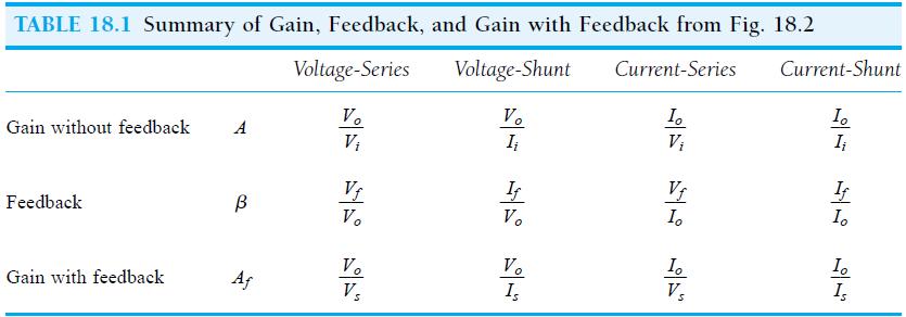
4 Feedback Connection Types Voltage Series Voltage Shunt Current Series Current Shunt Robert L. Boylestad, Electronic Devices and Circuit Theory,8 th Edition, Pearson Education Inc, ISBN: /8/2014 Muhammad Tilal 7 Gain with Feedback Robert L. Boylestad, Electronic Devices and Circuit Theory,8 th Edition, Pearson Education Inc, ISBN: /8/2014 Muhammad Tilal 8 4
5 Oscillator Operation A device which generates a periodic ac output signal without any form of input signal. Oscillator is a term mostly used for sine-wave signal generator whereas a square wave generator is usually termed as a multivibrator. Desirable features of a sine wave oscillator are Low distortion sinusoidal waveform Adjustable frequency range. Oscillation is a form of instability caused by feedback that reinforces a signal that would diminish otherwise due to energy loss. For this feedback to be regenerative, there are certain amplitude and phase conditions that must be fulfilled. Oscillators are designed with the known feedback characteristics. 12/8/2014 Muhammad Tilal 9 The Barkhausen Criterion In the block diagram, A is the amplifier gain while β is the feedback gain. Inordertomakethegiven system work as an oscillator, the loop gain must satisfy the Barkhausen criterion which is Aβ = 1. It is also important to note that not only the gain magnitude must be unity but the in phase signal reinforcement must also occur. Reactive elements especially the capacitors cause the shift in the gain magnitude and phase shift in amplifiers/ oscillators as a function of frequency. In general, there exists only one frequency at which the gain magnitude is unity and total phase shift is 0 degrees. Theodore F. Bogart, Jeffery S. Beasley, GuilermoRico, Electronics Devices and Circuits, 6 th Edition, Pearson Education Inc, ISBN: /8/2014 Muhammad Tilal 10 5
: The gain of a certain amplifier as a function of frequency is A(jw)= -16x 10 6 /jw.")
6 Oscillator Function Robert L. Boylestad, Electronic Devices and Circuit Theory,8 th Edition, Pearson Education Inc, ISBN: /8/2014 Muhammad Tilal 11 The Barkhausen Criterion Example 12-5 (Bogart): The gain of a certain amplifier as a function of frequency is A(jw)= -16x 10 6 /jw. A feedback path connected around it has β(jw)= 10 3 /(2x jw) 2. Will the system oscillate? If so, at what frequency. Solution: 12/8/2014 Muhammad Tilal 12 6
7 Types of Oscillators Four basic oscillator configurations will be covered which include RC Phase Shift Oscillator. Wien Bridge Oscillator. Collpits Oscillator. Hartley Oscillator. 12/8/2014 Muhammad Tilal 13 RC Phase Shift Oscillator RC phase shift oscillator is the simplest oscillator using an opamp in the inverting configuration(180 0 phaseshift). The loss in the RC network is compensated by the op-amp gain thatisvo/vi=-(rf/r). The op-amp drives three cascaded RC sections with phase shift. Thus the total phase shiftaroundtheloopis An important point here is that the total phase shift by three cascaded RC sections is equal to Theodore F. Bogart, Jeffery S. Beasley, GuilermoRico, Electronics Devices and Circuits, 6 th Edition, Pearson Education Inc, ISBN: /8/2014 Muhammad Tilal 14 7
8 RC Phase Shift Oscillator β= R 3 /[ (R 3-5RXC 2 ) + j(xc 3-6 R 2 XC) ] f o = 1/ 2πRC 6 Rf/R1= 29 Theodore F. Bogart, Jeffery S. Beasley, GuilermoRico, Electronics Devices and Circuits, 6 th Edition, Pearson Education Inc, ISBN: /8/2014 Muhammad Tilal 15 RC Phase Shift Oscillator Example 12-6 (Bogart): Design an RC Phase shift oscillator capable of oscillation at 100Hz. Theodore F. Bogart, Jeffery S. Beasley, GuilermoRico, Electronics Devices and Circuits, 6 th Edition, Pearson Education Inc, ISBN: /8/2014 Muhammad Tilal 16 8
9 Next Lecture The next lecture will cover the following topics Wien Bridge Oscillator. Collpits Oscillator. Hartley Oscillator. Oscillator Applications. 12/8/2014 Muhammad Tilal 17 References [1] Robert L. Boylestad, Electronic Devices and Circuit Theory, 8 th Edition, Pearson Education Inc, ISBN: [2] Theodore F. Bogart, Jeffery S. Beasley, Guilermo Rico, Electronics Devices andcircuits, 6 th Edition,PearsonEducationInc,ISBN: /8/2014 Muhammad Tilal 18 9
Electronics II. Previous Lecture
 Fall 204 (Rev. 3.0) Lecture 25 555 Timer IC (Mono Stable Operation) Voltage Controlled Oscillator and Phase Locked Loop Muhammad Tilal Department of Electrical Engineering CIIT Attock Campus Duplication
Electronics II. Previous Lecture
 Fall 2014(Rev. 3.0) Lecture 11 Differential Amplifier Muhammad Tilal Department of Electrical Engineering CIIT Attock Campus The logo and is the property of CIIT, Pakistan and subject to the copyrights
Electronics I. Last Time
 (Rev. 1.0) Electronics I Lecture 28 Introduction to Field Effect Transistors (FET s) Muhammad Tilal Department of Electrical Engineering CIIT Attock Campus The logo and is the property of CIIT, Pakistan
Electronics II. Previous Lecture
 Fall 2014 (Rev. 3.0) Lecture 08 FET Small Signal Analysis Muhammad Tilal Department of Electrical Engineering CIIT Attock Campus The logo and is the property of CIIT, Pakistan and subject to the copyrights
UNIVERSITI MALAYSIA PERLIS
 UNIVERSITI MALAYSIA PERLIS ANALOG ELECTRONICS II EMT 212 2009/2010 EXPERIMENT # 3 OP-AMP (OSCILLATORS) 1 1. OBJECTIVE: 1.1 To demonstrate the Wien bridge oscillator 1.2 To demonstrate the RC phase-shift
Figure 1: Closed Loop System
 SIGNAL GENERATORS 3. Introduction Signal sources have a variety of applications including checking stage gain, frequency response, and alignment in receivers and in a wide range of other electronics equipment.
EMT212 Analog Electronic II. Chapter 4. Oscillator
 EMT Analog Electronic II Chapter 4 Oscillator Objectives Describe the basic concept of an oscillator Discuss the basic principles of operation of an oscillator Analyze the operation of RC, LC and crystal
Feedback and Oscillator Circuits
 Chapter 14 Chapter 14 Feedback and Oscillator Circuits Feedback Concepts The effects of negative feedback on an amplifier: Disadvantage Lower gain Advantages Higher input impedance More stable gain Improved
Oscillators. An oscillator may be described as a source of alternating voltage. It is different than amplifier.
 Oscillators An oscillator may be described as a source of alternating voltage. It is different than amplifier. An amplifier delivers an output signal whose waveform corresponds to the input signal but
BENE 2163 ELECTRONIC SYSTEMS
 UNIVERSITI TEKNIKAL MALAYSIA MELAKA FAKULTI KEJURUTERAAN ELEKTRONIK DAN KEJURUTERAAN KOMPUTER BENE 263 ELECTRONIC SYSTEMS LAB SESSION 3 WEIN BRIDGE OSCILLATOR Revised: February 20 Lab 3 Wien Bridge Oscillator
Oscillator Principles
 Oscillators Introduction Oscillators are circuits that generates a repetitive waveform of fixed amplitude and frequency without any external input signal. The function of an oscillator is to generate alternating
Electronics & Comm. Lab
 Course name Electronics & Comm. Lab Lecture 1 Dr. Bedir B. Yousif E-mail: bedir.yousif@gmail.com Third Year-Comm Eng. Lecture: 1 hr. /week Section : 3 hrs. /week Subject Marks: 100 (50 works term + 50
CHAPTER 3 OSCILOSCOPE AND SIGNAL CONDITIONING
 CHAPTER 3 OSCILOSCOPE AND SIGNAL CONDITIONING OUTLINE Introduction to Signal Generator Oscillator Requirement for Oscillation Positive Feedback Amplifier Oscillator Radio Frequency Oscillator Introduction
21/10/58. M2-3 Signal Generators. Bill Hewlett and Dave Packard s 1 st product (1939) US patent No HP 200A s schematic
 US patent No HP 200A s schematic") M2-3 Signal Generators Bill Hewlett and Dave Packard s 1 st product (1939) US patent No.2267782 1 HP 200A s schematic 2 1 The basic structure of a sinusoidal oscillator. A positive feedback loop is formed
M2-3 Signal Generators Bill Hewlett and Dave Packard s 1 st product (1939) US patent No.2267782 1 HP 200A s schematic 2 1 The basic structure of a sinusoidal oscillator. A positive feedback loop is formed
Microelectronic Circuits - Fifth Edition Sedra/Smith Copyright 2004 by Oxford University Press, Inc.
 Feedback 1 Figure 8.1 General structure of the feedback amplifier. This is a signal-flow diagram, and the quantities x represent either voltage or current signals. 2 Figure E8.1 3 Figure 8.2 Illustrating
Applied Electronics II
 Applied Electronics II Chapter 4: Wave shaping and Waveform Generators School of Electrical and Computer Engineering Addis Ababa Institute of Technology Addis Ababa University Daniel D./Getachew T./Abel
UNIT 1 MULTI STAGE AMPLIFIES
 UNIT 1 MULTI STAGE AMPLIFIES 1. a) Derive the equation for the overall voltage gain of a multistage amplifier in terms of the individual voltage gains. b) what are the multi-stage amplifiers? 2. Describe
V out A v. Feedback Circuit
 Oscillators V out A v Feedback Circuit Figure.: Positive Feed Back The feedback network in an oscillator an input to the amplifier, which in turn an input to the feedback network. Since positive feedback
MAHALAKSHMI ENGINEERING COLLEGE TIRUCHIRAPALLI
 MAHALAKSHMI ENGINEERING COLLEGE TIRUCHIRAPALLI-621213. QUESTION BANK DEPARTMENT: EEE SUBJECT CODE: EE2203 SEMESTER : III SUBJECT NAME: ELECTRONIC DEVICES &CIRCUITS UNIT 4-AMPLIFIERS AND OSCILLATORS PART
EE301 ELECTRONIC CIRCUITS CHAPTER 2 : OSCILLATORS. Lecturer : Engr. Muhammad Muizz Bin Mohd Nawawi
 EE301 ELECTRONIC CIRCUITS CHAPTER 2 : OSCILLATORS Lecturer : Engr. Muhammad Muizz Bin Mohd Nawawi 2.1 INTRODUCTION An electronic circuit which is designed to generate a periodic waveform continuously at
Chapter.8: Oscillators
 Chapter.8: Oscillators Objectives: To understand The basic operation of an Oscillator the working of low frequency oscillators RC phase shift oscillator Wien bridge Oscillator the working of tuned oscillator
Lecture # 11 Oscillators (RC Circuits)
") December 2014 Benha University Faculty of Engineering at Shoubra ECE-312 Electronic Circuits (A) Lecture # 11 Oscillators (RC Circuits) Instructor: Dr. Ahmad El-Banna Agenda Introduction Feedback Oscillators
December 2014 Benha University Faculty of Engineering at Shoubra ECE-312 Electronic Circuits (A) Lecture # 11 Oscillators (RC Circuits) Instructor: Dr. Ahmad El-Banna Agenda Introduction Feedback Oscillators
Friday, 1/27/17 Constraints on A(jω)
") Friday, 1/27/17 Constraints on A(jω) The simplest electronic oscillators are op amp based, and A(jω) is typically a simple op amp fixed gain amplifier, such as the negative gain and positive gain amplifiers
Friday, 1/27/17 Constraints on A(jω) The simplest electronic oscillators are op amp based, and A(jω) is typically a simple op amp fixed gain amplifier, such as the negative gain and positive gain amplifiers
An active filter offers the following advantages over a passive filter:
 ACTIVE FILTERS An electric filter is often a frequency-selective circuit that passes a specified band of frequencies and blocks or attenuates signals of frequencies outside this band. Filters may be classified
Operational Amplifiers
 Fundamentals of op-amp Operation modes Golden rules of op-amp Op-amp circuits Inverting & non-inverting amplifier Unity follower, integrator & differentiator Introduction An operational amplifier, or op-amp,
Transistor Digital Circuits
 Recapitulation Transistor Digital Circuits The transistor Operating principle and regions Utilization of the transistor Transfer characteristics, symbols Controlled switch model BJT digital circuits MOSFET
Sub Code & Name: EC2251- ELECTRONIC CIRCUITS II Unit : I Branch : ECE Year:II
 Unit : I Branch : ECE Year:II Page 01 of 06 UNIT 1 FEEDBACK AMPLIFIERS 9 Block diagram, Loop gain, Gain with feedback, Effects of negative feedback Sensitivity and desensitivity of gain, Cut-off frequencies,
Homework Assignment 03 Solution
 Homework Assignment 03 Solution Question 1 Determine the h 11 and h 21 parameters for the circuit. Be sure to supply the units and proper sign for each parameter. (8 points) Solution Setting v 2 = 0 h
Test Your Understanding
 074 Part 2 Analog Electronics EXEISE POBLEM Ex 5.3: For the switched-capacitor circuit in Figure 5.3b), the parameters are: = 30 pf, 2 = 5pF, and F = 2 pf. The clock frequency is 00 khz. Determine the
Electronic Circuits EE359A
 Electronic Circuits EE359A Bruce McNair B206 bmcnair@stevens.edu 201-216-5549 Lecture 16 404 Signal Generators and Waveform-shaping Circuits Ch 17 405 Input summing, output sampling voltage amplifier Series
EC202- ELECTRONIC CIRCUITS II Unit- I -FEEEDBACK AMPLIFIER
 EC202- ELECTRONIC CIRCUITS II Unit- I -FEEEDBACK AMPLIFIER 1. What is feedback? What are the types of feedback? 2. Define positive feedback. What are its merits and demerits? 3. Define negative feedback.
Source Transformation
 HW Chapter 0: 4, 20, 26, 44, 52, 64, 74, 92. Source Transformation Source transformation in frequency domain involves transforming a voltage source in series with an impedance to a current source in parallel
Lecture 28 RC Phase Shift Oscillator using Op-amp
 Integrated Circuits, MOSFETs, OP-Amps and their Applications Prof. Hardik J Pandya Department of Electronic Systems Engineering Indian Institute of Science, Bangalore Lecture 28 RC Phase Shift Oscillator
ENE/EIE 211 : Electronic Devices and Circuit Design II Lecture 1: Introduction
 ENE/EIE 211 : Electronic Devices and Circuit Design II Lecture 1: Introduction 1/14/2018 1 Course Name: ENE/EIE 211 Electronic Devices and Circuit Design II Credits: 3 Prerequisite: ENE/EIE 210 Electronic
WAVEFORM GENERATOR CIRCUITS USING OPERATIONAL AMPLIFIERS
 15EEE287 Electronic Circuits & Simulation Lab - II Lab #8 WAVEFORM GENERATOR CIRCUITS USING OPERATIONAL AMPLIFIERS OBJECTIVE The purpose of the experiment is to design and construct circuits to generate
EE 368 Electronics Lab. Experiment 10 Operational Amplifier Applications (2)
") EE 368 Electronics Lab Experiment 10 Operational Amplifier Applications (2) 1 Experiment 10 Operational Amplifier Applications (2) Objectives To gain experience with Operational Amplifier (Op-Amp). To
EE 368 Electronics Lab Experiment 10 Operational Amplifier Applications (2) 1 Experiment 10 Operational Amplifier Applications (2) Objectives To gain experience with Operational Amplifier (Op-Amp). To
Table of Contents Lesson One Lesson Two Lesson Three Lesson Four Lesson Five PREVIEW COPY
 Oscillators Table of Contents Lesson One Lesson Two Lesson Three Introduction to Oscillators...3 Flip-Flops...19 Logic Clocks...37 Lesson Four Filters and Waveforms...53 Lesson Five Troubleshooting Oscillators...69
UNIT - IV FEEDBACK AMPLIFIERS & OSCILATTORS
 UNIT - IV FEEDBAK AMPLIFIES & OSILATTOS OBJETIVES i)the basics of feedback. ii)the properties of negative feedback. iii)the basic feedback topologies. iv)an example of the ideal feedback case. v)some realistic
Active Filters - Revisited
 Active Filters - Revisited Sources: Electronic Devices by Thomas L. Floyd. & Electronic Devices and Circuit Theory by Robert L. Boylestad, Louis Nashelsky Ideal and Practical Filters Ideal and Practical
Gechstudentszone.wordpress.com
 8.1 Operational Amplifier (Op-Amp) UNIT 8: Operational Amplifier An operational amplifier ("op-amp") is a DC-coupled high-gain electronic voltage amplifier with a differential input and, usually, a single-ended
Analog Electronic Circuits Code: EE-305-F
 Analog Electronic Circuits Code: EE-305-F 1 INTRODUCTION Usually Called Op Amps Section -C Operational Amplifier An amplifier is a device that accepts a varying input signal and produces a similar output
University of Pittsburgh
 University of Pittsburgh Experiment #6 Lab Report Active Filters and Oscillators Submission Date: 7/9/28 Instructors: Dr. Ahmed Dallal Shangqian Gao Submitted By: Nick Haver & Alex Williams Station #2
Operational Amplifiers
 Questions Easy Operational Amplifiers 1. Which of the following statements are true? a. An op-amp has two inputs and three outputs b. An op-amp has one input and two outputs c. An op-amp has two inputs
Thursday, 1/23/19 Automatic Gain Control As previously shown, 1 0 is a nonlinear system that produces a limit cycle with a distorted sinusoid for
 Thursday, 1/23/19 Automatic Gain Control As previously shown, 1 0 is a nonlinear system that produces a limit cycle with a distorted sinusoid for x(t), which is not a very good sinusoidal oscillator. A
Communication Systems. Department of Electronics and Electrical Engineering
 COMM 704: Communication Lecture 6: Oscillators (Continued) Dr Mohamed Abd El Ghany Dr. Mohamed Abd El Ghany, Mohamed.abdel-ghany@guc.edu.eg Course Outline Introduction Multipliers Filters Oscillators Power
Electronics II. 3. measurement : Tuned circuits
 Electronics II. 3. measurement : Tuned circuits This laboratory session involves circuits which contain a double-t (or TT), a passive RC circuit: Figure 1. Double T passive RC circuit module The upper
Lab 4 : Transistor Oscillators
 Objective: Lab 4 : Transistor Oscillators In this lab, you will learn how to design and implement a colpitts oscillator. In part II you will implement a RC phase shift oscillator Hardware Required : Pre
Introduction (cont )
") Active Filter 1 Introduction Filters are circuits that are capable of passing signals within a band of frequencies while rejecting or blocking signals of frequencies outside this band. This property of
Active Filter 1 Introduction Filters are circuits that are capable of passing signals within a band of frequencies while rejecting or blocking signals of frequencies outside this band. This property of
PURPOSE: NOTE: Be sure to record ALL results in your laboratory notebook.
 EE4902 Lab 9 CMOS OP-AMP PURPOSE: The purpose of this lab is to measure the closed-loop performance of an op-amp designed from individual MOSFETs. This op-amp, shown in Fig. 9-1, combines all of the major
MARIA COLLEGE OF ENGINEERING AND TECHNOLOGY, ATTOOR UNIT-1. Feedback Amplifiers
 MARIA COLLEGE OF ENGINEERING AND TECHNOLOGY, ATTOOR DEPARTMENT OF ELECTRONICS AND COMMUNICATION ENGINEERING ELECTRONIC CIRCUITS-II 2 MARKS QUESTIONS & ANSWERS UNIT-1 Feedback Amplifiers 1. What is meant
Positive Feedback and Oscillators
 Physics 3330 Experiment #5 Fall 2011 Positive Feedback and Oscillators Purpose In this experiment we will study how spontaneous oscillations may be caused by positive feedback. You will construct an active
Module 4 Unit 4 Feedback in Amplifiers
 Module 4 Unit 4 Feedback in mplifiers eview Questions:. What are the drawbacks in a electronic circuit not using proper feedback? 2. What is positive feedback? Positive feedback is avoided in amplifier
11. Chapter: Amplitude stabilization of the harmonic oscillator
 Punčochář, Mohylová: TELO, Chapter 10 1 11. Chapter: Amplitude stabilization of the harmonic oscillator Time of study: 3 hours Goals: the student should be able to define basic principles of oscillator
Expect to be successful, expect to be liked,
 Thought of the Day Expect to be successful, expect to be liked, expect to be popular everywhere you go. Oscillators 1 Oscillators D.C. Kulshreshtha Oscillators 2 Need of an Oscillator An oscillator circuit
LECTURE NOTES ELECTRONIC CIRCUITS II SYLLABUS
 FATIMA MICHAEL COLLEGE OF ENGINEERING & TECHNOLOGY Madurai Sivagangai Main Road Madurai - 625 020. [An ISO 9001:2008 Certified Institution] LECTURE NOTES EC6401 ELECTRONIC CIRCUITS - II SEMESTER: IV /
Feedback (and control) systems
 systems") Feedback (and control) systems Stability and performance Copyright 2007-2008 Stevens Institute of Technology - All rights reserved 22-1/23 Behavior of Under-damped System Y() s s b y 0 M s 2n y0 2 2 2
Feedback (and control) systems Stability and performance Copyright 2007-2008 Stevens Institute of Technology - All rights reserved 22-1/23 Behavior of Under-damped System Y() s s b y 0 M s 2n y0 2 2 2
OSCILLATORS AND WAVEFORM-SHAPING CIRCUITS
 OSILLATORS AND WAVEFORM-SHAPING IRUITS Signals having prescribed standard waveforms (e.g., sinusoidal, square, triangle, pulse, etc). To generate sinusoidal waveforms: o Positive feedback loop with non-linear
The steeper the phase shift as a function of frequency φ(ω) the more stable the frequency of oscillation
 the more stable the frequency of oscillation") It should be noted that the frequency of oscillation ω o is determined by the phase characteristics of the feedback loop. the loop oscillates at the frequency for which the phase is zero The steeper the
It should be noted that the frequency of oscillation ω o is determined by the phase characteristics of the feedback loop. the loop oscillates at the frequency for which the phase is zero The steeper the
Operational Amplifiers
 Operational Amplifiers Table of contents 1. Design 1.1. The Differential Amplifier 1.2. Level Shifter 1.3. Power Amplifier 2. Characteristics 3. The Opamp without NFB 4. Linear Amplifiers 4.1. The Non-Inverting
BHARATHIDASAN ENGINEERING COLLEGE
 BHARATHIDASAN ENGINEERING COLLEGE DEPARTMENT OF ELECTRONICS AND COMMUNICATION ENGINEERING EC6401 - ELECTRONIC CIRCUITS - II QUESTION BANK II- YEAR IV SEM ACDEMIC YEAR: 2016-2017 EVEN SEMESTER EC6401 ELECTRONIC
An Oscillator is a circuit which produces a periodic waveform at its output with only the dc supply voltage at the input. The output voltage can be
 An Oscillator is a circuit which produces a periodic waveform at its output with only the dc supply voltage at the input. The output voltage can be either sinusoidal or non sinusoidal depending upon the
Assume availability of the following components to DESIGN and DRAW the circuits of the op. amp. applications listed below:
 ========================================================================================== UNIVERSITY OF SOUTHERN MAINE Dept. of Electrical Engineering TEST #3 Prof. M.G.Guvench ELE343/02 ==========================================================================================
Microelectronic Circuits II. Ch 9 : Feedback
 Microelectronic Circuits II Ch 9 : Feedback 9.9 Determining the Loop Gain 9.0 The Stability problem 9. Effect on Feedback on the Amplifier Poles 9.2 Stability study using Bode plots 9.3 Frequency Compensation
Common-emitter amplifier, no feedback, with reference waveforms for comparison.
 Feedback If some percentage of an amplifier's output signal is connected to the input, so that the amplifier amplifies part of its own output signal, we have what is known as feedback. Feedback comes in
The Hartley Oscillator
 The Hartley Oscillator One of the main disadvantages of the basic LC Oscillator circuit we looked at in the previous tutorial is that they have no means of controlling the amplitude of the oscillations
Homework Assignment 13
 Question 1 Short Takes 2 points each. Homework Assignment 13 1. Classify the type of feedback uses in the circuit below (i.e., shunt-shunt, series-shunt, ) 2. True or false: an engineer uses series-shunt
Lecture 8: More on Operational Amplifiers (Op Amps)
") Lecture 8: More on Operational mplifiers (Op mps) Input Impedance of Op mps and Op mps Using Negative Feedback: Consider a general feedback circuit as shown. ssume that the amplifier has input impedance
Lecture 8: More on Operational mplifiers (Op mps) Input Impedance of Op mps and Op mps Using Negative Feedback: Consider a general feedback circuit as shown. ssume that the amplifier has input impedance
Chapter 13 Oscillators and Data Converters
 Chapter 13 Oscillators and Data Converters 13.1 General Considerations 13.2 Ring Oscillators 13.3 LC Oscillators 13.4 Phase Shift Oscillator 13.5 Wien-Bridge Oscillator 13.6 Crystal Oscillators 13.7 Chapter
Signal Generators and Waveform-Shaping Circuits
 CHAPTER 18 Signal Generators and Waveform-Shaping Circuits Figure 18.1 The basic structure of a sinusoidal oscillator. A positive-feedback loop is formed by an amplifier and a frequency-selective network.
An amplifier increases the power (amplitude) of an
 of an") Amplifiers Signal In Amplifier Signal Out An amplifier increases the power (amplitude) of an electronic signal, as shown in the figure above. Amplifiers are found everywhere in TV s, radios. MP3 players,
Amplifiers Signal In Amplifier Signal Out An amplifier increases the power (amplitude) of an electronic signal, as shown in the figure above. Amplifiers are found everywhere in TV s, radios. MP3 players,
Active Filter Design Techniques
 Active Filter Design Techniques 16.1 Introduction What is a filter? A filter is a device that passes electric signals at certain frequencies or frequency ranges while preventing the passage of others.
Precision Rectifier Circuits
 Precision Rectifier Circuits Rectifier circuits are used in the design of power supply circuits. In such applications, the voltage being rectified are usually much greater than the diode voltage drop,
Operational Amplifiers. Boylestad Chapter 10
 Operational Amplifiers Boylestad Chapter 10 DC-Offset Parameters Even when the input voltage is zero, an op-amp can have an output offset. The following can cause this offset: Input offset voltage Input
Lecture #1 Course Introduction and Amplifier Feedback Concepts
 Summer 2015 Ahmad El-Banna Faculty of Engineering Department of Electronics and Communications GEE336 Electronic Circuits II Lecture #1 Course Introduction and Amplifier Feedback Concepts Instructor: Dr.
ELEC207 LINEAR INTEGRATED CIRCUITS
 Concept of VIRTUAL SHORT For feedback amplifiers constructed with op-amps, the two op-amp terminals will always be approximately equal (V + = V - ) This condition in op-amp feedback amplifiers is known
1) Consider the circuit shown in figure below. Compute the output waveform for an input of 5kHz
 Consider the circuit shown in figure below. Compute the output waveform for an input of 5kHz") ) Consider the circuit shown in figure below. Compute the output waveform for an input of 5kHz Solution: a) Input is of constant amplitude of 2 V from 0 to 0. ms and 2 V from 0. ms to 0.2 ms. The output
) Consider the circuit shown in figure below. Compute the output waveform for an input of 5kHz Solution: a) Input is of constant amplitude of 2 V from 0 to 0. ms and 2 V from 0. ms to 0.2 ms. The output
SIDDHARTH GROUP OF INSTITUTIONS :: PUTTUR (AUTONOMOUS) Siddharth Nagar, Narayanavanam Road QUESTION BANK
 Siddharth Nagar, Narayanavanam Road QUESTION BANK") SIDDHARTH GROUP OF INSTITUTIONS :: PUTTUR (AUTONOMOUS) Siddharth Nagar, Narayanavanam Road 517583 QUESTION BANK Subject with Code : Electronic Circuit Analysis (16EC407) Year & Sem: II-B.Tech & II-Sem
SIDDHARTH GROUP OF INSTITUTIONS :: PUTTUR (AUTONOMOUS) Siddharth Nagar, Narayanavanam Road 517583 QUESTION BANK Subject with Code : Electronic Circuit Analysis (16EC407) Year & Sem: II-B.Tech & II-Sem
Homework Assignment 10
 Homework Assignment 10 Question The amplifier below has infinite input resistance, zero output resistance and an openloop gain. If, find the value of the feedback factor as well as so that the closed-loop
Testing Power Sources for Stability
 Keywords Venable, frequency response analyzer, oscillator, power source, stability testing, feedback loop, error amplifier compensation, impedance, output voltage, transfer function, gain crossover, bode
Feedback Amplifier & Oscillators
 256 UNIT 5 Feedback Amplifier & Oscillators 5.1 Learning Objectives Study definations of positive /negative feedback. Study the camparions of positive and negative feedback. Study the block diagram and
SKP Engineering College
 SKP Engineering College Tiruvannamalai 606611 A Course Material on Electronics Circuits-II M.Jerin Jose Associate Professor Electronics and Communication Engineering Department By Electronics and Communication
A Course Material on. Electronics Circuits II
 A Course Material on Electronics Circuits II By MS. R.P. MEENAAKSHISUNDHARI PROFESSOR DEPARTMENT OF ELECTRONICS & COMMUNICATION ENGINEERING SASURIE COLLEGE OF ENGINEERING VIJAYAMANGALAM 638 056 QUALITY
Electronics Interview Questions
 Electronics Interview Questions 1. What is Electronic? The study and use of electrical devices that operate by controlling the flow of electrons or other electrically charged particles. 2. What is communication?
PESIT - BANGALORE SOUTH CAMPUS PART A
 PESIT - BANGALORE SOUTH CAMPUS LESSON - PLAN FOR BASIC ELECTRONICS ENGG. Name of Faculty: Percentage of course Periods Reference/ Text books Topics covered Reference chapter covered Cumulative PART A Unit
Q Multiplication in the Wien-bridge Oscillator
 Multiplication in the Wien-bridge Oscillator The Wien-bridge oscillator earns its name from the typical bridge arrangement of the feedbac loops (fig.). This configuration is capable of delivering a clean
ME411 Engineering Measurement & Instrumentation. Winter 2017 Lecture 3
 ME411 Engineering Measurement & Instrumentation Winter 2017 Lecture 3 1 Current Measurement DC or AC current Use of a D Arsonval Meter - electric current carrying conductor passing through a magnetic field
Experiment 1: Amplifier Characterization Spring 2019
 Experiment 1: Amplifier Characterization Spring 2019 Objective: The objective of this experiment is to develop methods for characterizing key properties of operational amplifiers Note: We will be using
Scheme I Sample Question Paper
 Sample Question Paper Marks : 70 Time: 3 Hrs. Q.1) Attempt any FIVE of the following. 10 Marks a) Classify configuration of differential amplifier. b) Draw equivalent circuit of an OPAMP c) Suggest and
Application Note AN45
 Application Note Wien Bridge Oscillators using E 2 POTs by Applications Staff, October 1994 Wien Bridge Oscillators In 1939, William R. Hewlett (later of Hewlett-Packard fame) first combined the network
Chapter 14 Operational Amplifiers
 1. List the characteristics of ideal op amps. 2. Identify negative feedback in op-amp circuits. 3. Analyze ideal op-amp circuits that have negative feedback using the summing-point constraint. ELECTRICAL
Lesson Plan. Electronics 1-Total 51 Hours
 Lesson Plan. Electronics 1-Total 5s Unit I: Electrical Engineering materials:(10) Crystal structure & defects; Ceramic materials-structures, composites, processing and uses; Insulating laminates for electronics,
MAHARASHTRA STATE BOARD OF TECHNICAL EDUCATION (Autonomous) (ISO/IEC Certified) Summer 2016 EXAMINATIONS.
 (ISO/IEC Certified) Summer 2016 EXAMINATIONS.") Summer 2016 EXAMINATIONS Subject Code: 17321 Model Answer Important Instructions to examiners: 1) The answers should be examined by key words and not as word-to-word as given in the answer scheme. 2) The
Summer 2016 EXAMINATIONS Subject Code: 17321 Model Answer Important Instructions to examiners: 1) The answers should be examined by key words and not as word-to-word as given in the answer scheme. 2) The
MAHALAKSHMI ENGINEERING COLLEGE TIRUCHIRAPALLI UNIT I FEEDBACK AMPLIFIERS PART A (2 Marks)
") MAHALAKSHMI ENGINEERING COLLEGE TIRUCHIRAPALLI-621213. UNIT I FEEDBACK AMPLIFIERS PART A (2 Marks) 1. Name the types of feedback amplifiers. (AUC MAY 13, DEC06) Voltage Series feedback amplifier Voltage
MAHALAKSHMI ENGINEERING COLLEGE TIRUCHIRAPALLI-621213. UNIT I FEEDBACK AMPLIFIERS PART A (2 Marks) 1. Name the types of feedback amplifiers. (AUC MAY 13, DEC06) Voltage Series feedback amplifier Voltage
An input resistor suppresses noise and stray pickup developed across the high input impedance of the op amp.
 When you have completed this exercise, you will be able to operate a voltage follower using dc voltages. You will verify your results with a multimeter. O I The polarity of V O is identical to the polarity
Question Bank EC6401 ELECTRONIC CIRCUITS - II
 FATIMA MICHAEL COLLEGE OF ENGINEERING & TECHNOLOGY Madurai Sivagangai Main Road Madurai - 625 020. [An ISO 9001:2008 Certified Institution] SEMESTER: IV / ECE Question Bank EC6401 ELECTRONIC CIRCUITS -
CHAPTER 3: OSCILLATORS AND WAVEFORM-SHAPING CIRCUITS
 CHAPTER 3: OSCILLATORS AND WAVEFORM-SHAPING CIRCUITS In the design of electronic systems, the need frequently arises for signals having prescribed standard waveforms (e.g., sinusoidal, square, triangle,
Assist Lecturer: Marwa Maki. Active Filters
 Active Filters In past lecture we noticed that the main disadvantage of Passive Filters is that the amplitude of the output signals is less than that of the input signals, i.e., the gain is never greater
Dev Bhoomi Institute Of Technology Department of Electronics and Communication Engineering PRACTICAL INSTRUCTION SHEET REV. NO. : REV.
 Dev Bhoomi Institute Of Technology Department of Electronics and Communication Engineering PRACTICAL INSTRUCTION SHEET LABORATORY MANUAL EXPERIMENT NO. ISSUE NO. : ISSUE DATE: July 200 REV. NO. : REV.
CHAPTER 11. Feedback. Microelectronic Circuits, Seventh Edition. Copyright 2015 by Oxford University Press
 CHAPTER 11 Feedback Figure 11.1 General structure of the feedback amplifier. This is a signal-flow diagram, and the quantities x represent either voltage or current signals. Figure 11.2 Determining the
FEEDBACK AMPLIFIER. Learning Objectives. A feedback amplifier is one in which a fraction of the amplifier output is fed back to the input circuit
 C H P T E R6 Learning Objectives es Feedback mplifiers Principle of Feedback mplifiers dvantages of Negative Feedback Gain Stability Decreased Distortion Feedback Over Several Stages Increased Bandwidth