Fastech Co.,Ltd. Table of Contents
|
|
|
- Morgan Wilkinson
- 5 years ago
- Views:
Transcription
1
2 Fastech Co.,Ltd. Table of Contents 2
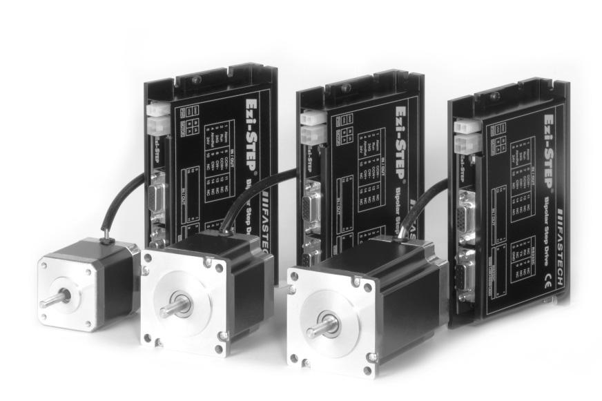
3 Before operating Thank you for purchasing Ezi-STEP. For high-speed and high-precision drive of a stepping motor, Ezi-STEP is an unique drive that adopts a new control scheme owing to an on-board high-performance 32bit digital signal processor. This manual describes handling, maintenance, repair, diagnosis and troubleshooting of Ezi- STEP. Before operating Ezi-STEP, thoroughly read this manual. 1. Precautions General Precautions Contents of this manual are subject to change without prior notice for functional improvement, change of specifications or user's better understanding. Thoroughly read the manual provided with the purchased Ezi-STEP. When the manual is damaged or lost, contact agent or Fastech at the address on the last page of the manual. Fastech is not responsible for a product breakdown due to user's dismantling the product, and such a breakdown is not covered by the warranty. Put the Safety First Before installing, operating and repairing the Ezi-STEP, thoroughly read the manual and fully understand the contents. Before operating the Ezi-STEP, understand the mechanical characteristics of the Ezi- STEP and related safety information and precautions. After reading the manual, keep the manual near the Ezi-STEP so that any user can read the manual whenever needed. This manual divides safety precautions into Warningand Attention. Attention If the user does not properly handle the product, the user may seriously or slightly injured and damages may occur only in the machine. Warning If the user does not properly handle the product, a dangerous situation (such as an electric shock) may occur resulting in deaths or serious injuries. Although precaution is only a Attention, a serious result could be caused depending on the situation. Follow safety precautions. 3
4 Fastech Co.,Ltd. Check the Status of the Ezi-STEP. Attention Do not install a damaged Ezi-STEP or a Ezi-STEP with a missing part. Otherwise, the user may get injured. Install. Attention Carefully move the Ezi-STEP. Dropping the product on the users foot may cause aninjury. Use non-flammable materials such as metal in the place where the Ezi-STEP is to be installed. Otherwise, a fire may occur. When installing several Ezi-STEP in a sealed place, install a cooling pan to keep the ambient temperature of the Ezi-STEP 55 or lower. Otherwise, a fire or other kinds of accidents may occur due to overheating. Connect Cables. Attention Check and Repair. Before connecting cables, check if input power is off. Otherwise, an electric shock or a fire may occur. All parameters of the Ezi-STEP were accordingly set in the factory. To change these parameters, read the manual carefully first. Otherwise, the machine may get damaged. The case of the Ezi-STEP is insulated from the ground of the internal circuit by the condenser. Ground the Ezi-STEP. Otherwise, an electric shock or a fire may occur. Warning Stop supplying power to the main circuit and wait for a while before checking or repairing the Ezi-STEP. Electricity remaining in the capacitor may cause danger. Do not change cabling while power is being supplied. Otherwise, the user may get injured or the step drive may get damaged. Do not reconstruct the Ezi-STEP. Otherwise, an electric shock may occur or the user may get injured. 4
5 2. Main Characteristics 1 Step-Out Detection(patent pending) EZi-STEP can detect the loss-of-synchronization of a stepping motor without the addition of an external sensor. By monitoring the voltage, the current, and the back-emf signal, the on-borad DSP estimates the current position of a rotor and enables to detect the loss-of-synchronization (so far seemingly impossible task in a conventional stepping motor drive), in turn realizing operation in high-speed region without worrying about loss-of-synchronization*. * effective only over 300 rpm Torque Detecting area of loss-of-synchronization 300 (rpm) 2 Microstep and Filtering(patent pending) High Precision microstep function and Filtering (Patent pending) The high-performance DSP resolves the basic resolution of 1.8up to maximum (1/250 steps). Contrary to a conventional drive, Ezi-STEP adjusts PWM control signal in every 25 usec, which makes it possible to more precise current control and realizes a high-precision microstep operation. 3 Software Damping(patent pending) Vibration suppression and High-speed operation (Patent pending) Ideally the applied currents to a stepping motor are a precise sinusoidal waves. But in practice the magnetic flux nonlinearity of the motor, the lowering of current due to the increase of back emf at highspeed and the lowering of the phase voltage are the sources of motor vibration. For these practice Ezi-STEP detects these nonlinearity with DSP and adjusts the phase of the current according to the pole position of the motor, drastically suppressing vibration. As reducing the vibration of the motor, it is possible to operate in high-speed regime. * This is real measured speed that using [pulse/rev]encoder. Software Damping Software Damping OFF Software Damping ON 5
6 Fastech Co.,Ltd. 4 Diverse Output Signal Monitoring Besides alarming loss-of-synchronization, there are various warning signals depending on the alarm issued. Also, Ezi-STEP provides an easy interface to communicate with an upper controller by issuing RUN/STOP signal. (The type of alarm issued can be identified by LED indicator) 5 Improve of High-Speed Driving Depending on the speed of a stepping motor, Ezi-STEP automatically increases the supply voltage and prevents the torque lowering due to the low effective operating voltage on a motor from the back emf voltage, in turn enabling a high-speed operation. Also, the software damping algorithm minimizes the vibration and prevents the loss-of-synchronization at high-speed. 3. Model Naming Part Numbering Ezi-STEP - STB S Length (S : Short, M : Middle, L : Long, XL : Extra Long) Size (42 : 42mm, 56 : 56mm) Motor+Drive Unit type(stb : Bipolar, STU : Unipolar) Drive Series Type Combination of Ezi-STEP 6
7 4. Specifications 4.1 Drive Specifications Condition Type Drive Method Input Voltage Operate Temp. Reserve Operate Humidity Reserve Vib. Resist. EzStep-BD-42-S/M/L EzStep-UD-42-S/M/L PWM drive with 32bit DSP 24 VDC 10% 0 ~ ~ ~85% RH (Non condensing) 10~90% RH (Non condensing) 0.5G EzStep-BD-56-S/M/L EzStep-UD-56-S/M/L Resolution(P/R) Max. Frequency Alarm Function LED Display 500~50,000 (Set by RS232C Communication) Default : 10, KHz (Duty 50%) Step-Out, Over-Current, Over-Heat, Over-Voltage, Power,Motor Connection Power Status(Green), Alarm Status(Red) CW Rotation(Yellow), CCW Rotation(Orange) Function I/O STOP Current Pulse Input Method Rotational Dir. Speed/Position Commamd Input Signals Output Signals 10% ~ 100% (Set by RS-232C Communication) Be setted to set value of STOP current after 0.1 second after motor stop. Default : 50% 1 Pulse / 2 Pulse (Set by RS-232C Communication) 1 Pulse: Pulse / Direction, 2 Pulse: CW / CCW Default : 2 Pulse CW / CCW (Set by RS232C Communication) Used when changing the direction of motor rotate. Default : CW Pulse train input (Photocoupler Input) Photocoupler Input : Motor Free/Alarm Reset Photocoupler Output : Alarm, Run/Stop 7
8 Fastech Co.,Ltd. 4.2 Drive Dimension(mm) 8
9 4.3 Motor Specifications Bipolar Series Bipolar - 42mm Unit : mm 9
10 Fastech Co.,Ltd Bipolar - 56mm Unit : mm 10
11 4.3.2 Unipolar Series Unipolar - 42mm Unit : mm 11
12 Fastech Co.,Ltd Unipolar - 56mm Unit : mm 12
13 5. Motor Torque Characteristics 5.1 Bipolar Motor 13
14 Fastech Co.,Ltd. 5.2 Unipolar Motor 14
15 6. Installation and Cabling 6.1 Notes on Installation 1) Ezi-STEP has been designed for indoor uses. 2) The ambient temperature of the room should be 0~50. 3) If the temperature of the case is higher than 50, radiate heat of the outside to cool down the case. 4) Do not install Ezi-STEP under direct rays, near magnetic or radioactive objects. 5) If you set more than 2 drives, you must set over 20mm horizontally and over 50mm vertically as shown below. 15
16 Fastech Co.,Ltd. 6.2 Connection Diagram Bipolar Connection Alarm Reset signal line is also used for Motor FREE signal. (For details, please refer to the section for Control Input/Output signal) 16
17 6.2.2 Unipolar Connection Alarm Reset signal line is also used for Motor FREE signal. (For details, please refer to the section for Control Input/Output signal) 17

18 Fastech Co.,Ltd. 7. Setting and Operating In case of Bipolar Drive 7.1 Status monitor LED Status LED Function and Condition Status Color Function Flash Condition PWR Green Power input indication Lights when power is ON Flashs when motor is Free status ALM Red Alarm indication Flash when protection function is activated (Identifiable which protection mode is activated by counting the flash times) CW Yellow Motor Rotation Direction Lights when motor rotate CW direction CCW Orange Motor Rotation Direction Lights when motor rotate CCW direction 18

19 7.1.2 Protection functions and LED flash times Flash Times Protection Conditions Overcurrent Overspeed Out of Synchronization Overheat Over regenerative Voltage Motor Connection Lowpower Excessive current flowed into a motor Motor speed exceeded 3000 rpm Abnormally, motor did not followed pulsed inputs Internal temperature of a motor drive exceeded 55 Back EMF more than 70V Power is ON without connection of motor cable to drive Power source voltage is below 20 volts s 1.2s Alarm LED flash (ex: Synchronization error) 7.2 Setting Up Parameters RS-232C serial communication port of a computer is used to set up various parameters of the motor drive. The set-up program is supplied with the product on a companion CD. It is recommended to make a copy of the program in any folder on your computer. Then please execute the program, named Ezi-STEP Setup.exe, from the folder. Please select an appropriate Prot No. and press button. Then it will display the various parameter values previously stored in the drive. : Display the parameter values stored in the drive : Store the parameter values displayed on the screen into the drive 19
20 Fastech Co.,Ltd Resolution Resolution means the number of pulses per one rotation of a motor. Select a desired resolution by pressing in button on Ezi-STEP Setup screen. The possible resolution values are 500~50,000. Press button to store the value selected into the drive. * The default factory setting is 10,000 [Pulses/Revolution] Stop Current Stop Current means the motor current value automatically set in 0.1 sec after motor stops. This is to prevent the overheat of a motor when the motor is under long time idling. Select a desired Stop Current by pressing in button on Ezi-STEP Setup screen. The unit of the selection values is a percentage. Press button to store the value selected into the drive. * The default factory setting is 50% Pulse Mode As the pulsed inputs, a user can choose One-pulse-mode (Pulse/Dir) or Two-pulsemode(CW/CCW). Select a desired pulse mode by pressing in button on Ezi-STEP Setup screen. Press button to store the value selected into the drive. * The default factory setting is Two pulse input mode (CW/CCW) Rotation Direction The direction of the motor rotation can be selected either in CW(clockwise) or in CCW(Counter Clockwise). Select a desired rotation direction by pressing in button on Ezi-STEP Setup screen. Press button to store the value selected into the drive. * The default factory setting is CW(clockwise). 20
21 7.2.5 Polarity Run Signal Run/Stop output method can be selected that indicate the motor running status.select a desired method by pressing in button on Ezi-STEP Setup screen. Press button to store the value selected into the drive. * The default factory setting is Normal Polarity Alarm Signal Alarm signal output method can be selected when error happens. Select a desired method by pressing in button on Ezi-STEP Setup screen. Press button to store the value selected into the drive. * The default factory setting is Normal Polarity Alarm Reset Signal Input methol of Motor Free / Alarm Reset can be selected. Select a desired method by pressing in button on Ezi-STEP Setup screen. Press button to store the value selected into the drive. * The default factory setting is Normal. [CAUTION] : When you selet lnverse : It can be Motor Free status when powen is applied to Ezi-STEP during Signal Connector(CN2)is not connected. The power led(green)is flash to show the status of Motor Free Motor Type This parameter can not be changed. 21
22 Fastech Co.,Ltd. 8. Connectors 8.1 Power Connector(CN1) 8.2 Motor Connector(CN2)- Bipolar Drive Motor Connector(CN2)- Unipolar Drive 8.4 Signal Connector(CN4)

23 8.5 RS232C(CN3) 9. External Wiring Diagram PC Control Unit Motion Controller Network Motion Controller PLC Power +24VDC Type Power Cable Motor Cable Signal Cable RS232C Cable Standard Length cm Max. Length 2m 20m 20m 15m 23
24 Fastech Co.,Ltd. 10. Control signal Input/Output Description 10.1 Input signals CW, CCW Input Motor Free Input Alarm Reset Input 24
25 10.2 Output signals Alarm Output Run/Stop Output 25
26 Fastech Co.,Ltd. 26
27 27
28
Ezi-STEP MINI Characteristics
 Ezi-STEP MINI Characteristics Ezi-STEP MINI is a micro stepping system that incorporates a motor and DSP (Digital Signal Processor) equipped drive that is integrated seamlessly together as a system. This
Operating Manual.
 Operating Manual www.fastech.co.kr FASTECH Co.,Ltd. Table of Contents 1. Precautions 2. Main characteristics 3. Drive Specification and Dimension 4. Motor Specification and Size 4.1 Ezi-SERVO-BT-42 Series
No Gain Tuning. Hunting. Closed Loop System
 2 No Gain Tuning Conventional servo systems, to ensure machine performance, smoothness, positional error and low servo noise, require the adjustment of its servo s gains as an initial crucial step. Even
$MPTFE -PPQ 4UFQQJOH 4ZTUFN.JOJBUVSJ[FE $PNQBDU 4J[F $MPTFE -PPQ 4ZTUFN /P (BJO 5VOJOH /P )VOUJOH )JHI 3FTPMVUJPO 'BTU 3FTQPOTF
VOUJOH )JHI 3FTPMVUJPO 'BTU 3FTQPOTF") $MPTFE -PPQ 4UFQQJOH 4ZTUFN.JOJBUVSJ[FE $PNQBDU 4J[F $MPTFE -PPQ 4ZTUFN /P (BJO 5VOJOH /P )VOUJOH )JHI 3FTPMVUJPO 'BTU 3FTQPOTF ú ú ú ú ú ú 2 2 No Gain Tuning Conventional servo systems, to ensure machine
$MPTFE -PPQ 4UFQQJOH 4ZTUFN.JOJBUVSJ[FE $PNQBDU 4J[F $MPTFE -PPQ 4ZTUFN /P (BJO 5VOJOH /P )VOUJOH )JHI 3FTPMVUJPO 'BTU 3FTQPOTF ú ú ú ú ú ú 2 2 No Gain Tuning Conventional servo systems, to ensure machine
Position Table Function. Closed Loop System. Network Based Motion Control. No Gain Tuning
 2 2 Position Table Function Position Table can be used for motion control by digital input and output signals of host controller. You can operate the motor directly by sending the position table number,
Integrated Servo Motor UCS57
 Integrated Servo Motor Introduction is a new generation of high performance digital integrated servo drive motor, which is a series of low voltage AC servo products integrated with AC servo motor and drive
CL86T. 24~80VDC, 8.2A Peak, Closed-loop, No Tuning. Descriptions. Closed-loop. Stepper. Applications. Datasheet of the Closed-loop Stepper CL86T
 CL86T Closed-loop Stepper 24~80VDC, 8.2A Peak, Closed-loop, No Tuning Closed-loop, eliminates loss of synchronization Broader operating range higher torque and higher speed Reduced motor heating and more
30-80V, 8.2A Peak, No Tuning, Nulls loss of Synchronization
 2-phase Hybrid Servo Drive 30-80V, 8.2A Peak, No Tuning, Nulls loss of Synchronization Closed-loop, eliminates loss of synchronization Broader operating range higher torque and higher speed Reduced motor
DMX-K-DRV-17 Integrated Step Motor Driver & Basic Controller
 DMX-K-DRV-17 Integrated Step Motor Driver & Basic Controller DMX-K-DRV-17 Manual - 1 - rev 1.35 COPYRIGHT 2015 ARCUS, ALL RIGHTS RESERVED First edition, June 2007 ARCUS TECHNOLOGY copyrights this document.
Driver specifications Motor Specifications P.57
 specifications Motor Specifications P. General Specifications Unipolar Bipolar Model number USDP BSDP Input source DC V/ V Source current A Basic specifications Environment Protection class Operation environment
Datasheet of the MEZ Stepper Servo Drive MEZ 2D VDC, 8.2A Peak, Closed-loop, No Tuning. Version
 Datasheet of the MEZ Stepper Servo Drive MEZ D880 4-75VDC, 8.A Peak, Closed-loop, No Tuning Version 0.1.1 http://www.motionking.com Features Step and direction control Closed position loop for no loss
ES86 Series Closed-loop Stepper Drive + Motor System (Drive+ Motor/Encoder)
") ES86 Series Closed-loop Stepper Drive + Motor System (Drive+ Motor/Encoder) Traditional stepper motor drive systems operate open loop providing position control without feedback. However, because of this,
ES86 Series Closed-loop Stepper Drive + Motor System (Drive+ Motor/Encoder) Traditional stepper motor drive systems operate open loop providing position control without feedback. However, because of this,
DMX-K-DRV-23 Integrated Step Motor Driver & Basic Controller
 DMX-K-DRV-23 Integrated Step Motor Driver & Basic Controller DMX-K-DRV-23 Manual - 1 - rev 1.35 COPYRIGHT 2013 ARCUS, ALL RIGHTS RESERVED First edition, June 2007 ARCUS TECHNOLOGY copyrights this document.
ies-2309 Integrated Easy Servo
 Datasheet of the integrated easy servo motor ies-09 ies-09 Integrated Easy Servo Motor + Drive + Encoder, 0-0VDC, NEMA, 0.9Nm Features Easy servo control technology to combine advantages of open-loop stepper
Integrated Easy Servo
 ies 1706 Integrated Easy Servo Motor + Drive + Encoder, 18 32VDC, NEMA17, 0.6Nm Features Easy servo control technology to combine advantages of open loop stepper systems and brushless servo systems Closed
ES86 Series Closed-loop Stepper Drive + Motor System (Drive+ Motor/Encoder)
") ES86 Series Closed-loop Stepper Drive + Motor System (Drive+ Motor/Encoder) Traditional stepper motor drive systems operate open loop providing position control without feedback. However, because of this,
ES86 Series Closed-loop Stepper Drive + Motor System (Drive+ Motor/Encoder) Traditional stepper motor drive systems operate open loop providing position control without feedback. However, because of this,
Closed Loop Stepping System with Network based Motion Controller
 Closed Loop Stepping System with Network based Motion Controller 2 Position Table Function Position Table is used for motion control by digital input and output signals of host controller. You can operate
A 1/10/2013. Hardware Manual STR2M Step Motor Drive
 Hardware Manual 5000-235-001 STR2M Step Motor Drive 5000-235-001 STR2M Contents Safety Instructions... 3 Introduction... 5 Features... 5 Block Diagram... 6 Getting Started... 7 Mounting the Drive... 8
3DM phase Digital Stepper Drive
 3DM2283 3-phase Digital Stepper Drive 150-220VAC, 0.5-8.2A peak, Auto-configuration, Low Noise Anti-Resonance provides optimal torque and nulls mid-range instability Motor auto-identification and parameter
Servo Motor Driver. 4. Specifications: Digital Driver Model ACS806. Digital Technology, max. 80 V DC / 6.0 A, W. 1. Product Description:
 Digital Driver Model ACS806 Digital Technology, max. 80 V DC / 6.0 A, 50 400 W 1. Product Description: Leadshine's fully digital AC servo drive ACS806 is developed with 32-bit DSP based on advanced control
HBS Series Hybrid Servos
 Hybrid Servos 46 Hybrid Servos From the stepper and servo, but surpass them in many applications! HBS Series Hybrid Servos Closed-loop, eliminates loss of synchronization The HBS series use an encoder
Dynamo Brushless DC Motor and GreenDriveTM Manual
 Dynamo Brushless DC Motor and GreenDriveTM Manual This manual was developed as a guide for use by FIRST Robotics Teams using Controller Part Number 840205-000 in conjunction with the Nidec Dynamo BLDC
DCS Series Brush DC Servo Drive. Datasheet
 DCS Series Brush DC Servo Drive Datasheet Version DCS-2014-01 http://www.primopal.com DCS series Brush DC Servo Drives Description PrimoPal s DCS series Brush DC Servo Drive are fully digital brushed servo
Datasheet of the Easy Servo Drive ES-D VAC or VDC, 8.2A Peak, Close-loop, No Tuning. Version
 Datasheet of the Easy Servo Drive ES-D1008 0-70 V or 30-100VDC, 8.A Peak, Close-loop, No Tuning Version 0.1.0 http://www.leadshine.com Features Step and direction control Closed position loop for no loss
Compact Actuator DRL Series
 Introduction Precision Rack & Pinion Linear Linear Actuators Heads DRL LH Accessories Before Using a Linear Motion System Compact Actuator DRL Series Additional Information Technical Reference F-1 General
Contents. USER MANUAL NI ISM-7400 Integrated Stepper
 USER MANUAL NI ISM-7400 Integrated Stepper This manual describes the NI ISM-7400 integrated stepper. It describes electrical and mechanical characteristics of the devices, as well as I/O functionality.
ST5-S ST10-S Rev. A1
 ST ST5-S ST1-S 92-27 Rev. A1 92-27 Rev. A1 ST5/1-S Hardware manual Table Of Contents Contents Introduction... 3 Features... 3 Block Diagrams... 4 Getting Started... 5 Connecting to the PC using RS-232...
:PMM-BA ø 60 ø 86 ø 106
 Pulse I/ (AC power input) The -Phase Stepping Driver PMM-BA-- PMM-BA-- ACV/V -step/half-step ( x division) ( x divisions) Applicable motor ø ø ø Characteristics lexible These drivers can drive various
2-Phase Stepping Motor Driver with Built-in Indexer UI2120G
 -Phase Stepping Motor Driver with Built-in Indexer UI10G Additional Information Technical Reference F-1 General Information G-1 Introduction AS AS PLUS ASC RK CFK CSK PMC UMK CSK PK/PV PK UI10G EMP01 EMP0
Galvanometer Scanner Driver GVD0 Series Instruction Manual
 CX5-091 Sep. 2018 Ver. 6.1 Galvanometer Scanner Driver GVD0 Series Instruction Manual CITIZEN CHIBA PRECISION CO., LTD. 1 Contents Preface.2 1. Specification..3 2. Product Overview..4 3. Input / Output
Hardware Manual. STR4 & STR8 Step Motor Drives
 Hardware Manual STR4 & STR8 Step Motor Drives 92-3J 92-3J Contents Introduction... 3 Features... 3 Block Diagram... 4 Getting Started... 5 Mounting the Drive... 6 Connecting the Power Supply... 6 Drive
PMM-BA PMM-BA AC 100 V/115 V Full-step/half-step (500 x 1 divisions) (500 x 2 divisions)
 (500 x 2 divisions)") Pulse I/ (AC power input) The -Phase Stepping Driver - PMM-BA-- AC V/ V ull-step/half-step ( x divisions) ( x divisions) Applicable motors ø ø Characteristics High-speed type These drivers are high-speed
Pulse I/ (AC power input) The -Phase Stepping Driver - PMM-BA-- AC V/ V ull-step/half-step ( x divisions) ( x divisions) Applicable motors ø ø Characteristics High-speed type These drivers are high-speed
VFD - D700 Series Specifications. The latest low-cost variable speed control solution for centrifugal pumps.
 VFD - D700 Series Specifications The latest low-cost variable speed control solution for centrifugal pumps. Built-in PID Control to maintain pressure, flow, measured value, and much more 125% overload
ES86 Series Closed-loop Stepper Drive + Motor System (ES-D808 Drive+ Motor/Encoder)
") ES86 Series Closed-loop Stepper Drive + Motor System (ES-D808 Drive+ Motor/Encoder) Traditional stepper motor drive systems operate open loop providing position control without feedback. However, because
ES86 Series Closed-loop Stepper Drive + Motor System (ES-D808 Drive+ Motor/Encoder) Traditional stepper motor drive systems operate open loop providing position control without feedback. However, because
Connection and Operation
 Connection and Operation Names and Functions of Parts 4 1 Monitor Display LED Indicators DG60 1 5 Motor Connector Power Connector Indication Color Function When Activated OPERATI Green Power Supply Indication
DCS810 Brushed DC Servo Drive
 Datasheet of Brushed DC Servo Drive DCS810 DCS810 Brushed DC Servo Drive 18-80VDC, 0-20A, 20-400W Based on DSP control technology and high smooth servo control algorithm Parameter visible tuning tools,
Engineering Data AC Servo Drive HA-680
 Engineering Data AC Servo Drive HA-680 QUICKLINK www.harmonicdrive.de/1110 SAFETY GUIDE For FHA series, RSF series, HA series Read this manual thoroughly before designing the application, installation,
High Intensity LED Stroboscope Digital Tachometer DT-361/365. Instruction manual. Be sure to read before use.
 98585A High Intensity LED Stroboscope Digital Tachometer DT-361/365 Instruction manual Be sure to read before use. Before use, please carefully read these safety precautions as well as instructions, and
Hardware Manual. STR2 Step Motor Drive
 Hardware Manual STR2 Step Motor Drive STR2 Hardware Manual Contents Safety Instructions... 3 Introduction... 5 Features... 5 Block Diagram... 6 Getting Started... 7 Mounting the Drive... 8 Connecting the
SD4030B3-M02D. Bipolar micro step driver for 2-phase stepping motor SD4030B3. Instruction manual. Low cost Low vibration RoHS compliant
 SD4030B3-M02D Bipolar micro step driver for 2-phase stepping motor SD4030B3 Instruction manual Low cost Low vibration RoHS compliant Introduction Thank you for purchasing SD4030B3. This manual describes
BLuAC5 Brushless Universal Servo Amplifier
 BLuAC5 Brushless Universal Servo Amplifier Description The BLu Series servo drives provide compact, reliable solutions for a wide range of motion applications in a variety of industries. BLu Series drives
PSW-002. Fiber Optic Polarization Switch. User Guide
 PSW-002 Fiber Optic Polarization Switch User Guide Version: 1.0 Date: May 30, 2014 General Photonics, Incorporated is located in Chino California. For more information visit the company's website at: www.generalphotonics.com
Technical Document. for the. CB 016N6 Driver Card
 Technical Document for the CB 06N6 Driver Card Contents Introduction 3 Page New functions 3 3 Dimensions 3 4 I/O Interface 4 5 Connectors 4-5 6 Switches 5-6 7 Potentiometers 7 8 LEDs and Error Indications
Datasheet of the Easy Servo Drive ES-D VDC, 8.0A Peak, Closed-loop, No Tuning
 Datasheet of the Easy Servo Drive ES-D508 0-45VDC, 8.0A Peak, Closed-loop, No Tuning Version 1. http://www.leadshine.com Features Step and direction control Closed position loop for no loss of movement
5-Phase Stepping Motor and Microstep Driver Package
 ORIENTAL MOTOR GENERAL CATALOGUE Motor and Microstep Driver Package RFK Features B-154 Specifications B-157 Speed - Torque Characteristics B-158 Dimensions B-159 List of motor and Driver Combinations B-16
ST5-S ST10-S Rev. D 2/7/2014
 ST ST5-S ST1-S 92-27 Rev. D 2/7/214 92-27 Rev. D ST5/1-S Hardware manual Table Of Contents Contents Introduction... 3 Features... 3 Block Diagrams... 4 Getting Started... 5 Connecting to the PC using RS-232...
815-BR SERVO AMPLIFIER FOR BRUSH SERVOMOTORS
 815-BR SERVO AMPLIFIER FOR BRUSH SERVOMOTORS USER GUIDE September 2004 Important Notice This document is subject to the following conditions and restrictions: This document contains proprietary information
Operation Manual. Congratulations on purchasing your high quality AIMS Power pure sine inverter!
 Operation Manual Congratulations on purchasing your high quality AIMS Power pure sine inverter! It is very important that you read and understand this instruction manual completely prior to use. Contained
BLuAC5 Brushless Universal Servo Amplifier
 BLuAC5 Brushless Universal Servo Amplifier Description The BLu Series servo drives provide compact, reliable solutions for a wide range of motion applications in a variety of industries. BLu Series drives
HA-680 Series Manual
 AC Servo Driver for 24 VDC Power Supply HA-680 Series Manual (For FHA-8C, 11C, 14C/RSF-3C,5B/8B,11B, and 14B) Thank you very much for your purchasing our HA-680 series AC servo driver for 24 VDC power
D.C. BRUSHLESS MOTORS DRIVE. BLD07-IT Service Manual
 D.C. BRUSHLESS MOTORS DRIVE BLD07-IT Service Manual INTECNO s.r.l. Via Caduti di Sabbiuno n. 9/E 40011 Anzola Emilia (BO) - Italy tel. 051.19985350 fax 051.19985360 www.intecno-srl.com INDEX Description
AFC Series AFC -20HG AFC-20SE
 Piezoelectric Feeder Controller AFC Series AFC -20HG AFC-20SE Instruction Manual Thank you for purchasing the controller manufactured by BFC Limited. Please read this instruction manual thoroughly before
Two-phase Digital Stepper Motor Driver SD Low Vibration Low Noise Low Power. Characteristics. Performance Index. Product Codes:
 Two-phase Digital Stepper Motor Driver SD-20403 Product Codes: 001700 Low Vibration Low Noise Low Power Characteristics 32-bit DSP digital control mode Low vibration. low noise. low power Flexible micro-stepping,
Bholanath. User s Manual. Precision Engineering Pvt.Ltd. BHSSD Step Servo Driver. Note:-
 Bholanath Precision Engineering Pvt.Ltd. User s Manual Step Servo - BHSS - 750 W BHSSD Step Servo Driver Note:- Step servo drive & motor are matched pair with BH-75Vac power supply Email : support@bholanath.in
General-Purpose AC Servo. MELSERVO-JE Servo amplifier INSTRUCTION MANUAL (TROUBLE SHOOTING)
") General-Purpose AC Servo MELSERVO-JE Servo amplifier INSTRUCTION MANUAL (TROUBLE SHOOTING) D Safety Instructions Please read the instructions carefully before using the equipment. To use the equipment
General-Purpose AC Servo MELSERVO-JE Servo amplifier INSTRUCTION MANUAL (TROUBLE SHOOTING) D Safety Instructions Please read the instructions carefully before using the equipment. To use the equipment
DSB810A Digital DC Servo Driver Manual V1.0
 User s Manual For DSB810A Digital DC Servo Driver Version 1.0 2007 All Rights Reserved Attention: Please read this manual carefully before using the driver! The content in this manual has been carefully
HA-680 Series Manual
 AC Servo Driver for 24 VDC Power Supply HA-680 Series Manual (For FHA-8C, 11C, 14C/RSF-3A, and 5A) Thank you very much for your purchasing our HA-680 series AC servo driver for 24 VDC power supply. Parameter
RoHS Directive-Compliant Compact Linear Actuators DRL Series. Features
 Motorized ctuators RoHS Directive-Compliant Compact Linear ctuators DRL Series In the compact linear actuator DRL Series, the drive mechanism adopts a -phase stepping motor with ball screw. This series
Diameter ø50mm Shaft type Absolute Multi-turn Rotary Encoder
 Dia ø50mm Shaft type Absolute Multi-turn otary Encoder Features Compact size of dia ø50mm Parallel data / SSI data transmission type Total 23bit resolution(8388608 divisions) of 10bit single-turn(1024
BC145 SIGNAL ISOLATOR BOARD
 BC145 SIGNAL ISOLATOR BOARD 4/17 Installation & Operating Manual MN1373 Any trademarks used in this manual are the property of their respective owners. Important: Be sure to check www.baldor.com to download
Copyright / Trademarks -This manual and its contents are copyrighted. -You may not copy this manual,in whole or part,without written consent of
 Safety Precautions Observe the following notices to ensure personal safety or to prevent accidents. To ensure that you use this product correctly, read this User s Manual thoroughly before use. Make sure
General-Purpose AC Servo. MELSERVO-J4 Servo amplifier INSTRUCTION MANUAL (TROUBLE SHOOTING)
") General-Purpose AC Servo MELSERVO-J4 Servo amplifier INSTRUCTION MANUAL (TROUBLE SHOOTING) K Safety Instructions Please read the instructions carefully before using the equipment. To use the equipment
General-Purpose AC Servo MELSERVO-J4 Servo amplifier INSTRUCTION MANUAL (TROUBLE SHOOTING) K Safety Instructions Please read the instructions carefully before using the equipment. To use the equipment
General-Purpose AC Servo. MELSERVO-J4 Servo amplifier INSTRUCTION MANUAL (TROUBLE SHOOTING)
") General-Purpose AC Servo MELSERVO-J4 Servo amplifier INSTRUCTION MANUAL (TROUBLE SHOOTING) N Safety Instructions Please read the instructions carefully before using the equipment. To use the equipment
General-Purpose AC Servo MELSERVO-J4 Servo amplifier INSTRUCTION MANUAL (TROUBLE SHOOTING) N Safety Instructions Please read the instructions carefully before using the equipment. To use the equipment
DM8010 tm. Hardware Reference Manual. Document Revision B3 May 16, 2018
 tm Hardware Reference Manual Document Revision B3 May 16, 2018 MICROKINETICS CORPORATION 3380 Town Point Drive Suite 330 Kennesaw, Georgia 30144 Tel: (770) 422-7845 Fax: (770) 422-7854 Table Of Contents
Displacement Sensor CD5 Series
 Sensor Head Instruction Manual Displacement Sensor CD5 Series Laser Type (CD5-L_25,CD5-_30,CD5-_85,CD5-_150,CD5-W350,CD5-W500,CD5-W2000) Table of Contents page SAFETY PRECAUTIONS... 3 Meanings of Safety
General-Purpose AC Servo. MELSERVO-JE Servo amplifier INSTRUCTION MANUAL (TROUBLE SHOOTING)
") General-Purpose AC Servo MELSERVO-JE Servo amplifier INSTRUCTION MANUAL (TROUBLE SHOOTING) B Safety Instructions Please read the instructions carefully before using the equipment. To use the equipment
General-Purpose AC Servo MELSERVO-JE Servo amplifier INSTRUCTION MANUAL (TROUBLE SHOOTING) B Safety Instructions Please read the instructions carefully before using the equipment. To use the equipment
Chapter 9: Troubleshooting
 AFC1500 Operations Manual Chapter 9: Troubleshooting (Rev. 6: 10/09) Chapter 9: Troubleshooting Page 9-1 Chapter 9: Troubleshooting 9.1 Abnormal Conditions. When an abnormal condition is detected by the
rev B 6/1/2016 STM17. Hardware Manual
 STM17 Hardware Manual Contents Introduction...3 Block Diagram STM17S, STM17Q...4 Block Diagram STM17C...5 Safety Instructions...6 Getting Started...7 Installing Software...7 Mounting Hardware...7 Additional
KSC-10 Kelvin Speed controller 10A Rev.00 of 23/01/17
 Kelvin Speed controller 10A Tel : +34 93 422 70 33 1 The KSC-10 is a 1 Quadrant digital servo amplifier for direct current motor with permanent magnets of up to 600 Watts. It permits speed regulation in
General-Purpose AC Servo. MELSERVO-JE Servo amplifier INSTRUCTION MANUAL (TROUBLE SHOOTING)
") General-Purpose AC Servo MELSERVO-JE Servo amplifier INSTRUCTION MANUAL (TROUBLE SHOOTING) F Safety Instructions Please read the instructions carefully before using the equipment. To use the equipment
General-Purpose AC Servo MELSERVO-JE Servo amplifier INSTRUCTION MANUAL (TROUBLE SHOOTING) F Safety Instructions Please read the instructions carefully before using the equipment. To use the equipment
Rotary Servo Actuator
 Rotary Servo Actuator TYPICAL APPLICATIONS Unmanned air vehicles - tactical, medium long endurance and MALE / HALE vehicles - Control surfaces requiring servo actuation Target drones - surface control,
USER S MANUAL. 580 TV Line OSD Bullet Camera With 2 External Illuminators
 USER S MANUAL 580 TV Line OSD Bullet Camera With 2 External Illuminators Please read this manual thoroughly before operation and keep it handy for further reference. WARNING & CAUTION CAUTION RISK OF ELECTRIC
Features. Anti-Resonance. Microstep Emulation. Torque Ripple Smoothing. Command Signal Smoothing. Dynamic Current Control. Self Test & Auto Setup
 STM Integrated Steppers Drive Motor Controller The STM is an integrated Drive+Motor+Controller, fusing step motor and drive technologies into a single device, offering savings on space, wiring and cost
Instruction for setting the ICE2 HV 120 governor mode with 800MX
 Instruction for setting the ICE2 HV 120 governor mode with 800MX We recommend using the governor mode of ESC with 800MX motor. If you are using the governor mode in Castle ICE2 HV 120 ESC, we recommend
S, SX & SXF Series S, SX & SXF. Packaged. Packaged Microstepping Systems. The X Series... An Indexer and Drive
 Catalog 8-2/US S, SX & SXF Systems The S Family of drives and drive/indexer systems are standalone, packaged microstepping systems. Designed for reliability, the S step and direction input drive, the SX
Artisan Technology Group is your source for quality new and certified-used/pre-owned equipment
 Artisan Technology Group is your source for quality new and certified-used/pre-owned equipment FAST SHIPPING AND DELIVERY TENS OF THOUSANDS OF IN-STOCK ITEMS EQUIPMENT DEMOS HUNDREDS OF MANUFACTURERS SUPPORTED
High Frequency Sinewave Guardian TM Filter
 High Frequency Sinewave Guardian TM Filter 380V 480V TECHNICAL REFERENCE MANUAL FORM: SHF-TRM-E REL. April 2015 REV. 001 2015 MTE Corporation Caution Prior to start up; confirm the drive operation mode
High Performance Microstep Systems
 P315/P315X High Performance Microstep Systems Description Common Features Torques from 65 to 3, oz-in. with speeds to 3, RPM continuous. Dip switch selectable resolutions up to 5,8 steps per revolution.
Z4D-F. LED-type Micro Displacement Sensor with Many Features in a Compact Body. Micro Displacement Sensor. Ordering Information.
 / Length Micro Sensor LED-type Micro Sensor with Many Features in a Compact Body Compact body only /4th the volume of our previous product. % cost reduction over our previous product. High performance
Series 48 Air Cooled Laser & UC-2000 Quick Start Guide
 Important Read all Danger, Warning, Caution terms, symbols, and instructions located in the (Laser Safety Hazard information) sections in the Series 48 Laser Operation Manuals. http://www.synrad.com/synrad/docroot/resources/libraries/manuals.
MU110-16R(K) Digital output module 16 channel. User guide
 Digital output module 16 channel. User guide") MU110-16R(K) Digital output module 16 channel User guide MU110-16R(K)_2016.12_0220_EN All rights reserved Subject to technical changes and misprints akytec GmbH Vahrenwalder Str. 269 A 30179 Hannover Germany
MU110-16R(K) Digital output module 16 channel User guide MU110-16R(K)_2016.12_0220_EN All rights reserved Subject to technical changes and misprints akytec GmbH Vahrenwalder Str. 269 A 30179 Hannover Germany
MU110-8R(K) Digital output module 8 channel. User guide
 Digital output module 8 channel. User guide") MU110-8R(K) Digital output module 8 channel User guide MU110-8R(K)_2019.01_0296_EN All rights reserved Subject to technical changes and misprints akytec GmbH Vahrenwalder Str. 269 A 30179 Hannover Germany
MU110-8R(K) Digital output module 8 channel User guide MU110-8R(K)_2019.01_0296_EN All rights reserved Subject to technical changes and misprints akytec GmbH Vahrenwalder Str. 269 A 30179 Hannover Germany
Model 12PR1A. User Manual
 12 Volt Ultra-Portable Antenna Rotor System Single Axis Model 12PR1A User Manual Document Rev 1.1 Copyright 2013-14 Portable Rotation Patent Pending Page 1 Warranty All products sold by Portable Rotation
SPECIFICATION, CONTROLS AND ACCESSORIES
 AS440 Automatic Voltage Regulator (AVR) SPECIFICATION, CONTROLS AND ACCESSORIES English Original Instructions A043Y697 (Issue 2) Table of Contents 1. DESCRIPTION... 1 2. SPECIFICATION... 3 3. CONTROLS...
SV2Dx Servo Drives SV200 Servo Drives for DC-Powered Applications
 24 to 60 VDC input 10 A cont., 20 A peak output current Compact size for multi-axis applications Ideal for OEMs Designed for use with J Series motors Wide range of control options 8 regular digital inputs,
MV110-8AS. Analog input module 8 channel. User guide
 MV110-8AS Analog input module 8 channel User guide MV110-8AS_2016.12_0226_EN All rights reserved Subject to technical changes and misprints Contents 1 Description... 2 1.1 Function... 2 1.2 RS485 network...
6.9 Jump frequency - Avoiding frequency resonance
 E581595.9 Jump frequency - Avoiding frequency resonance : Jump frequency : Jumping width Function Resonance due to the natural frequency of the mechanical system can be avoided by jumping the resonant
0.01kV (0 to ±0.99 kv)
") Handheld Electrostatic Meter Series IZH10 Easy-to-use handheld electrostatic meter Rated charge amount range: ±20.0 kv Minimum display unit: 0.1kV (±1.0 to ±20.0 kv) Check the current situation before
Handheld Electrostatic Meter Series IZH10 Easy-to-use handheld electrostatic meter Rated charge amount range: ±20.0 kv Minimum display unit: 0.1kV (±1.0 to ±20.0 kv) Check the current situation before
User manuel. Hybrid stepper servo drive
 User manuel Hybrid stepper servo drive 1 Overview Hybridstepper servo drive system integrated servo control technology into the digital step driver. It adopts typical tricyclic control method which include
How to use the UJ20 external inputs/outputs and modes / Troubleshooting
 How to use the UJ20 external inputs/outputs and modes / Troubleshooting Page Title 1 How to use the UJ20 external inputs/outputs and modes / Troubleshooting 2 Emergency stop of UV irradiation 1: EMERGENCY
Electronically Commutated (EC) Motor Control with Solo, Select and Sync PWM Boards
 Motor Control with Solo, Select and Sync PWM Boards") Electronically Commutated (EC) Motor Control with Solo, Select and Sync PWM Boards The Solo, Select and Sync PWM boards provide a pulse-width modulated (PWM) signal to the EC motor to control fan speed.
Electronically Commutated (EC) Motor Control with Solo, Select and Sync PWM Boards The Solo, Select and Sync PWM boards provide a pulse-width modulated (PWM) signal to the EC motor to control fan speed.
Safety Precautions. Copyright / Trademarks
 Safety Precautions Observe the following notices to ensure personal safety or to prevent accidents. To ensure that you use this product correctly, read this User s Manual thoroughly before use. Make sure
PULSE TRAIN DRIVER P 1. User s Manual RS1 / RS2 / RS3 RS1C / RS2C / RS3C RSD1 / RSD2 / RSD3 RSDG1 / RSDG2 / RSDG3 EUMC KE4. Ver. 2.
 PULSE TRAIN DRIVER P 1 User s Manual RS1 / RS2 / RS3 RS1C / RS2C / RS3C RSD1 / RSD2 / RSD3 RSDG1 / RSDG2 / RSDG3 Ver. 2.00 EUMC181200 KE4 CONTENTS P1 User s Manual Important information before reading
UMK M A A. RoHS-Compliant. 2-Phase Stepping Motor and Driver Package. Features. Product Number Code. Product Line
 RoHS-Compliant Stepping Motor and Package UMK Series Additional Information Technical reference Page F- The UMK Series is a -phase stepping motor (resolution: per rotation) with easy-handling AC input
User manual Interroll Frequency Inverter IP55 PD-A-400-1A5-55 PD-A-230-2A5-55. Version 1.1 (08/2011) en Original instructions. Frequency Inverter
 en Original instructions. Frequency Inverter") Frequency Inverter Input 1 Input 2 Power Trip Power In Power Out Sensor Input Communications Part ASI Data Fault User manual Interroll Frequency Inverter IP55 PD-A-400-1A5-55 PD-A-230-2A5-55 Chapter-ID:
Frequency Inverter Input 1 Input 2 Power Trip Power In Power Out Sensor Input Communications Part ASI Data Fault User manual Interroll Frequency Inverter IP55 PD-A-400-1A5-55 PD-A-230-2A5-55 Chapter-ID:
VFSC9 ELECTRONIC SPEED CONTROLLER. Mounting and operating instructions
 ELECTRONIC SPEED CONTROLLER Mounting and operating instructions Table of contents SAFETY AND PRECAUTIONS 3 PRODUCT DESCRIPTION 4 ARTICLE CODES 4 INTENDED AREA OF USE 4 TECHNICAL DATA 4 STANDARDS 5 WIRING
Troubleshooting 12. This section explains the items to check when problems occur, and troubleshooting by the use of error displays or operation state.
 Troubleshooting 12 This section explains the items to check when problems occur, and troubleshooting by the use of error displays or operation state. 12-1 Actions for Problems..........................................
This section is specifically about safety matters
 6 4 ) 1 6 4 1 -, 1 8-4 6-4 1 6 4 7 + 6 1 ) 7 ) 4 ) 6 1-6 6-4. 4. 0 J E? A Thank you for choosing this Mitsubishi transistorized Inverter option. This instruction manual gives handling information and precautions
Series 48 Water Cooled Laser & UC-2000 Quick Start Guide
 Important Read all Danger, Warning, Caution terms, symbols, and instructions located in the (Laser Safety Hazard information) sections in the Series 48 Laser Operation Manuals. http://www.synrad.com/synrad/docroot/resources/libraries/manuals