DMX-K-DRV-23 Integrated Step Motor Driver & Basic Controller
|
|
|
- Ella Higgins
- 6 years ago
- Views:
Transcription

1 DMX-K-DRV-23 Integrated Step Motor Driver & Basic Controller DMX-K-DRV-23 Manual rev 1.35
2 COPYRIGHT 2013 ARCUS, ALL RIGHTS RESERVED First edition, June 2007 ARCUS TECHNOLOGY copyrights this document. You may not reproduce or translate into any language in any form and means any part of this publication without the written permission from ARCUS. ARCUS makes no representations or warranties regarding the content of this document. We reserve the right to revise this document any time without notice and obligation. Revision History: st release nd release rd release th release th release th release th release Firmware Compatibility: V36 If your module s firmware version number is less than the listed value, contact Arcus for the appropriate documentation. Arcus reserves the right to change the firmware without notice. DMX-K-DRV-23 Manual rev 1.35
3 Table of Contents 1. INTRODUCTION FEATURES PART NUMBERING SCHEME ELECTRICAL AND THERMAL SPECIFICATIONS DIMENSIONS CONNECTIVITY PIN CONNECTOR (2MM) DIPSWITCH FOR ANALOG/DIGITAL SELECTION DMX-K-DRV-23 INTERFACE CIRCUIT Pulse/Dir (CW/CCW) Inputs Enable Input Alarm Output STEPPER MOTOR SPECIFICATIONS OPERATING TEMPERATURE GENERAL STEPPER MOTOR SPECIFICATIONS STEPPER MOTOR TORQUE STEPPER MOTOR DRIVER SPECIFICATIONS MICROSTEP CURRENT CONTROL OVER TEMPERATURE ALARM DIO CONTROL ANALOG SPEED CONTROL DRIVER CONFIGURATION CONFIGURATION CABLES SOFTWARE DEFAULT SETTINGS DRIVER MODE DEFAULT SETTINGS CONTROL MODE DMX-K-DRV-23 Manual rev 1.35
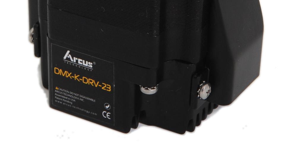
4 1. Introduction DMX-K-DRV-23 is an integrated stepper driver and motor product. Feature highlights include: simple controller functionality, analog speed control, and an over temperature alarm output Features VDC voltage input - 100mA to 2.5A peak current setting - Full/Half/Quarter/16 microstep - One clock (Pulse/Dir) or Two clock (CW/CCW) support - 200K maximum pulse rate support - 16K maximum pulse rate (controller mode) - 34K maximum pulse rate (analog mode) - 4 selectable motion profiles (controller mode) - 10-bit analog input - Opto-isolated differential Pulse/Dir (CW/CCW) inputs - Opto-isolated driver enable input - Opto-isolated over-temperature alarm output In position output (controller mode) - Integrated controller using DIO control - Integrate analog speed control - NEMA 23 motor available in various stack sizes Part Numbering Scheme DMX-K-DRV Motor Stack Size 2 Double 3 Triple Contacting Support For technical support, contact: support@arcus-technology.com. Or, contact your local distributor for technical support. DMX-K-DRV-23 Manual rev 1.35
5 2. Electrical and Thermal Specifications Parameter Min Max Units Main Power Input V A Analog Inputs 0 +5 V - 25 ma Forward Diode Current (PUL/DIR) - 25 ma Forward Diode Current (ENABLE) - 45 ma Operating Temperature C Storage Temperature C Table The supply current should match the driver current setting. 2 Based on component ratings. DMX-K-DRV-23 Manual rev 1.35
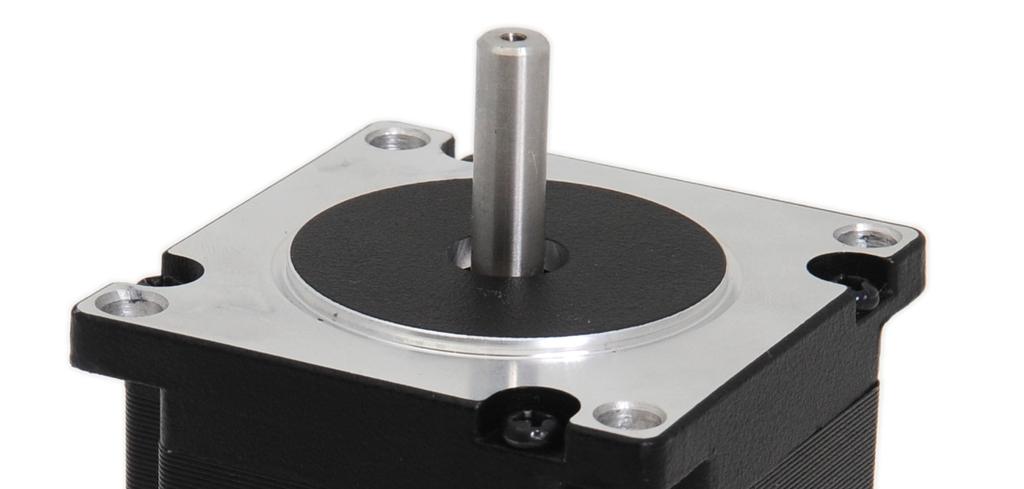
6 3. Dimensions Figure 3.0 NEMA 23 Models L (inches) DMX-K-DRV-23-2 (double stack) 2.20 DMX-K-DRV-23-3 (triple stack) 2.99 Table 3.0 DMX-K-DRV-23 Manual rev 1.35

7 4. Connectivity Pin Connector (2mm) DMX-K-DRV-23 comes with a single row 10 pin connector shown below. Figure 4.0 Pin # Wire Color In/Out Name Description 1 Black I GND Power Input Ground 2 Red I V+ +12 to +24VDC Power 3 Gray NC NC Reserved. Do not connect 4 White/Red O ALARM Alarm output 5 Orange/White I ENABLE Enable motor input 6 Orange I OPTO Opto-supply for enable input 7 Blue/White Negative direction input / Negative I DIR- (CCW-) counter-clockwise input 8 Blue Positive direction input / Positive I DIR+ (CCW) counter-clockwise input 9 Green/White Negative pulse input / Negative I PUL- (CW-)/AI clockwise input /Analog input 10 Green Positive pulse input / Positive I PUL+ (CW+) clockwise input Table 4.0 DMX-K-DRV-23 Manual rev 1.35
 side.")
8 Description: Manufacturer: Part Number: Female 10 pin 2mm single row HIROSE DF3-10S-2C (10 pin female connector) DF3-2428SC (female pin) 4.2. Dipswitch for Analog/Digital Selection DMX-K-DRV-23 can operate in digital and analog control modes. The mode is selected with the dipswitch pictured below. Figure 4.1 When configured to Driver or Control mode, the dipswitch should be moved to the digital (D) side. When configured to Analog mode, the dipswitch should be moved to the analog (A) side. DMX-K-DRV-23 Manual rev 1.35

9 4.3. DMX-K-DRV-23 Interface Circuit Figure Pulse/Dir (CW/CCW) Inputs DMX-K-DRV-23 supports both one-clock (PULSE/DIR) and two-clock (CW/CCW) inputs. One-clock uses the PUL signal as the pulse train input position control and the DIR signal as the direction input signal for direction control. Figure 4.3 Two-clock uses CW as the clockwise pulse input and CCW as the counter clockwise pulse input for position control. DMX-K-DRV-23 Manual rev 1.35
 inputs are opto-isolated differential inputs with a 470 Ohm resistor. Figure 4.")
10 Figure 4.4 Depending on the direction polarity setting, actual direction of the rotation can be configured for the application. Pulse/Dir (CW/CCW) inputs are opto-isolated differential inputs with a 470 Ohm resistor. Figure 4.5 shows the detailed schematic of the opto-isolated pulse and direction inputs. Figure 4.5 DMX-K-DRV-23 Manual rev 1.35
11 Figure 4.6 shows an example of wiring the pulse and direction inputs with a differential output. Figure 4.6 Figure 4.7 shows an example of wiring the pulse and direction inputs with an open-collector output. Figure 4.7 Important Note: The recommended voltage between the differential inputs is 5V. An additional current limiting resistor is required to support larger voltages. DMX-K-DRV-23 Manual rev 1.35
12 Enable Input Enable input is an opto-isolated input with a 470 Ohm resistor and diode. Figure 4.8 shows the detailed schematic of the opto-isolated enable input. Figure Alarm Output Alarm output is an opto-isolated output with a 100 Ohm resistor. Figure 4.9 shows a wiring example of the opto-isolated alarm output. Figure 4.9 DMX-K-DRV-23 Manual rev 1.35


13 5. Stepper Motor Specifications 5.1. Operating Temperature Electronic components used in the DMX-K-DRV-23 have a maximum ambient operating temperature of 85 C. DMX-K-DRV-23 electronics are potted with heat-conductive compound to the housing to evenly distribute the heat and reduce any hot spots in the driver. The housing also has integrated fins to better dissipate the heat. DMX-K-DRV-23 should be mounted securely to a metallic bracket that can also act as a heat-sink. During operation, the step motor section typically becomes hotter than the driver section. Having the step motor mounted to a heat sink will help dissipate the heat generated by the step motor. DMX-K-DRV-23 mounting orientation should be such that the fins are oriented vertically for better convection and heat dissipation. See Figure 5.0 below. Figure 5.0 DMX-K-DRV-23 Manual rev 1.35
14 5.2. General Stepper Motor Specifications The following charts show the specifications of the standard step motors used for DMX-K-DRV-23 products. All standard DMX-K-DRV-23 step motors are 1.8 degree bi-polar step motors. Resistance Inductance Stack Size Max Amp / Phase Inertia / Phase / Phase Double 3.9A 0.9 Ohm 2.5 mh 1.64 oz-in 2 Triple 3.9A 1.13 Ohm 3.6 mh 2.62 oz-in 2 Table 5.0 Stack Size Max Axial Force Max Radial Force Double 15N 75N Triple 15N 75N Table Stepper Motor Torque The torque output of the DMX-K-DRV-23 will vary depending on the supply voltage, driver current, motor type, and target speed of the motor. Increasing the drive current will increase the torque output, however the operating temperature will also increase. While decreasing the drive current will reduce the torque output, it will help reduce the operating temperature as well. Each application will need to adjust this setting to find the desired driver output. Using a higher voltage to power the DMX-K-DRV-23 will allow the motor to run at faster speeds. Note that increasing the voltage will not increase the maximum holding torque of the motor. Stepper motors in general will drop off in torque as the target speed of the motor is increased. The following torque curve shows the expected torque output based on the motor speed of the DMX-K-DRV-23. DMX-K-DRV-23 Manual rev 1.35
15 Figure 5.1 DMX-K-DRV-23 Manual rev 1.35
16 6. Stepper Motor Driver Specifications 6.1. Microstep The standard DMX-K-DRV-23 motor is a 1.8 degree motor, which translates to 200 full steps per revolution. These steps can be divided with microstepping to increase position resolution. The available microstep settings and their corresponding resolution can be found in Table 6.0. Microstep Steps/Revolution Full Step 200 Half Step 400 Quarter Step 800 1/16 Step 3200 Table Current Control DMX-K-DRV-23 has a configurable current setting from 100mA to 2.5A peak current. Driver current is set to Run Current when the pulse input is detected and remains in run current while the pulse input is detected. Once the pulse input has been idle for the duration defined by the Idle Time, the Idle Current will be used to hold the motor in position. The holding torque of the DMX-K-DRV-23 will be defined by the Idle Current Over Temperature Alarm DMX-K-DRV-23 has a temperature sensor to detect over heating of the driver. Temperature sensing is done only when the driver is enabled. When the temperature goes over the over-temperature alarm value 70 C, the Alarm Output is turned on. If the temperature goes below the 68 C, the alarm output is turned off. If the temperature goes over 75 C, the driver is automatically turned off and remained off until the temperature goes below 68 C. The automatic temperature shutdown feature can be enabled or disabled during the configuration process. Refer to Section 7 for further details. For additional information regarding temperature precautions, refer to section 5.1. For details on the over temperature alarm, see Figure 6.0. DMX-K-DRV-23 Manual rev 1.35
17 Alarm remains on and the driver is automatically turned off Alarm signal is turned on Driver Temperature Alarm turned off, driver turned on Actual driver temperature Time Figure DIO Control The DMX-K-DRV-23 has built-in controller capability. When configured in controller mode, the DIR, ENABLE, PUL and ALARM signals are used for DIO Control. Configuration for DIO control is detailed in Section 7. See Table 6.1 for the signal descriptions. These descriptions are only valid while the DMX-K-DRV- 23 is in controller mode. While in controller mode, the motor is always enabled. If the direction signal is toggled while the enable signal is off, the alarm signal will turn on because of its use in the Dynamic Configuration algorithm. Therefore, it is advised to toggle the enable signal before selecting a motion profile. This will prevent the alarm output from erroneously triggering. In/Out Name Description I ENABLE Select 2 bit motion profile (Bit 0) I DIR-/DIR+ Select 2 bit motion profile (Bit 1) I PUL-/PUL+ Trigger motion profile or abort a current move operation O ALARM In-position output 1 Table 6.1 DMX-K-DRV-23 Manual rev 1.35
18 1 If Over Temp Shutdown feature is enabled, the alarm output operates as a temperature alarm output and not an in-position output. To use as an in-position output, the Over Temp Shutdown feature must be disabled. Available movement types and their corresponding parameters are shown in the table below. Move Target Position Description Type Speed(PPS) JOG+/- Move the motor continuously. N/A ABS Move the motor to the target position. 32 bit number INC Increment the motor by the target position. 32 bit number Table Example Timing Diagram for DIO Control Assuming that the parameters shown in Table 6.3 are stored in the DMX-K-DRV- 23, the timing diagram in Figure 6.1 and Table 6.4 provide an example of DIO control use. Motion Profile Target Move Type ENA DIR Position Speed(PPS) 0 0 JOG JOG ABS INC Table 6.3 Figure 6.1 DMX-K-DRV-23 Manual rev 1.35
19 Case Motion Profile PUL ENA DIR Result DMX-K-DRV-23 is idle. Chosen motion profile is JOG+. DMX-K-DRV-23 is jogging in the positive direction at a speed of pps. Motion starts on the rising edge of the PUL signal. DMX-K-DRV-23 has stopped all motion on the falling edge of the PUL signal. DMX-K-DRV-23 is idle. Chosen motion profile is ABS with a target position of DMX-K-DRV-23 is moving to pulse position Note that the motor will stop once the desired position is reached, regardless of the PUL signal DMX-K-DRV-23 is idle. Table Analog Speed Control The DMX-K-DRV-23 has built-in analog speed control capability. When configured in analog mode, the DIR and AI (PUL-/CW-) signals are used for analog speed control. In analog speed control, the speed of the motor is determined by the analog input value [0 - +5VDC]. The direction of the motor is determined by the differential direction input. After configuring the motor for analog speed control mode, the dipswitch SW1 must be moved to the analog side, designated by the A label. When configuring the motor back to Driver or Control mode, the dipswitch must be reverted back to the digital side, designated by the D label. See figure 4.1 for details. The maximum allowable speed in analog speed control is 32K steps/second. The RPM output of the motor at this speed is dependent on the microstep setting. An analog input of 25mV or below will result in an idle state. The speed will increase linearly as the analog input voltage increases towards +5V. Figure 6.2 shows details regarding the speed of the motor in relation to the analog input voltage. DMX-K-DRV-23 Manual rev 1.35
20 Figure 6.2 DMX-K-DRV-23 Manual rev 1.35

21 7. Driver Configuration DMX-K-DRV-23 uses patented Dynamic Configuration Method to read and write the driver parameters using the control signals (Pulse, Dir, Enable, and Alarm) of the driver. Dynamic Configuration eliminates the need for jumpers, switches, resistors, potentiometers and communication port for reading and setting the driver parameters. This results in a simple and cost-effective device Configuration Cables The DMX-CFG-USB-K23 cable is used to configure the DMX-K-DRV-23. This 10-pin cable allows communication with the software detailed in section 7.2 to set driver parameters Software Make sure that the USB driver is installed properly before attempting to run the configuration software. See the DMX-CFG-USB Cables manual for details on configuration. Figure 7.0 shows the configuration interface Figure Microstep Setting - Full, Half (1/2), Quarter (1/4), Sixteen(1/16). 2. Run Current - 100mA to 2.5A peak current. 3. Idle Current - 100mA to 2.5A peak current. 4. Idle Time msec to 10 sec. 5. Direction Polarity - Toggles direction polarity. 6. Clock mode - One-clock or Two-clock mode. DMX-K-DRV-23 Manual rev 1.35
22 7. Controller or Driver mode: A. Driver mode requires pulse and direction signals to move the motor. B. Controller mode uses the Enable and Direction inputs to specify a set of motion parameters and the Pulse input to start and stop motion. 8. Over Temperature Shutdown - Determines whether or not the DMX- K-DRV-23 disables when the temperature rises above a specified threshold. See Figure 6.0 for details. 9. DIO motion parameters - Up to four motion profiles can be set and used when the DMX-K-DRV-23 is in controller mode. 10. Read - Reads settings from the device and displays them. 11. Write - Writes the displayed settings to the device. 12. Save - Save driver settings to a text file. 13. Open - Load previously saved driver settings from a text file. 14. Close - Exit the configurator Default Settings Driver Mode µstep Run Current (A) Idle Current (A) Idle Time (ms) Dir Clock Mode Over Temp Shutdown CW One Driver ON Table Default Settings Control Mode Motion Profile Move Target ENA DIR Type Position Speed(PPS) 0 0 ABS ABS ABS ABS Table 7.1 DMX-K-DRV-23 Manual rev 1.35
23 Contact Information Arcus Technology, Inc Independence Drive Livermore, CA The information in this document is believed to be accurate at the time of publication but is subject to change without notice. DMX-K-DRV-23 Manual rev 1.35
DMX-K-DRV-17 Integrated Step Motor Driver & Basic Controller
 DMX-K-DRV-17 Integrated Step Motor Driver & Basic Controller DMX-K-DRV-17 Manual - 1 - rev 1.35 COPYRIGHT 2015 ARCUS, ALL RIGHTS RESERVED First edition, June 2007 ARCUS TECHNOLOGY copyrights this document.
3DM phase Digital Stepper Drive
 3DM2283 3-phase Digital Stepper Drive 150-220VAC, 0.5-8.2A peak, Auto-configuration, Low Noise Anti-Resonance provides optimal torque and nulls mid-range instability Motor auto-identification and parameter
ES86 Series Closed-loop Stepper Drive + Motor System (Drive+ Motor/Encoder)
") ES86 Series Closed-loop Stepper Drive + Motor System (Drive+ Motor/Encoder) Traditional stepper motor drive systems operate open loop providing position control without feedback. However, because of this,
ES86 Series Closed-loop Stepper Drive + Motor System (Drive+ Motor/Encoder) Traditional stepper motor drive systems operate open loop providing position control without feedback. However, because of this,
ES86 Series Closed-loop Stepper Drive + Motor System (ES-D808 Drive+ Motor/Encoder)
") ES86 Series Closed-loop Stepper Drive + Motor System (ES-D808 Drive+ Motor/Encoder) Traditional stepper motor drive systems operate open loop providing position control without feedback. However, because
ES86 Series Closed-loop Stepper Drive + Motor System (ES-D808 Drive+ Motor/Encoder) Traditional stepper motor drive systems operate open loop providing position control without feedback. However, because
ES86 Series Closed-loop Stepper Drive + Motor System (Drive+ Motor/Encoder)
") ES86 Series Closed-loop Stepper Drive + Motor System (Drive+ Motor/Encoder) Traditional stepper motor drive systems operate open loop providing position control without feedback. However, because of this,
ES86 Series Closed-loop Stepper Drive + Motor System (Drive+ Motor/Encoder) Traditional stepper motor drive systems operate open loop providing position control without feedback. However, because of this,
CL86T. 24~80VDC, 8.2A Peak, Closed-loop, No Tuning. Descriptions. Closed-loop. Stepper. Applications. Datasheet of the Closed-loop Stepper CL86T
 CL86T Closed-loop Stepper 24~80VDC, 8.2A Peak, Closed-loop, No Tuning Closed-loop, eliminates loss of synchronization Broader operating range higher torque and higher speed Reduced motor heating and more
Datasheet of the Easy Servo Drive ES-D VAC or VDC, 8.2A Peak, Close-loop, No Tuning. Version
 Datasheet of the Easy Servo Drive ES-D1008 0-70 V or 30-100VDC, 8.A Peak, Close-loop, No Tuning Version 0.1.0 http://www.leadshine.com Features Step and direction control Closed position loop for no loss
PKG-232-MBC12-PS-CBL System Diagram and Specifications
 PKG-232-MBC12-PS-CBL System Diagram and Specifications Included Components: 23Y206S-LW8-MS Stepper Motor MBC12101 Stepper Driver PSA80V4A-1 Power Supply CBL-18AWG-04C-010-MS Motor Cable WIR-1007-18-YEL
30-80V, 8.2A Peak, No Tuning, Nulls loss of Synchronization
 2-phase Hybrid Servo Drive 30-80V, 8.2A Peak, No Tuning, Nulls loss of Synchronization Closed-loop, eliminates loss of synchronization Broader operating range higher torque and higher speed Reduced motor
Datasheet of the Easy Servo Drive ES-D VDC, 8.0A Peak, Closed-loop, No Tuning
 Datasheet of the Easy Servo Drive ES-D508 0-45VDC, 8.0A Peak, Closed-loop, No Tuning Version 1. http://www.leadshine.com Features Step and direction control Closed position loop for no loss of movement
Datasheet of the MEZ Stepper Servo Drive MEZ 2D VDC, 8.2A Peak, Closed-loop, No Tuning. Version
 Datasheet of the MEZ Stepper Servo Drive MEZ D880 4-75VDC, 8.A Peak, Closed-loop, No Tuning Version 0.1.1 http://www.motionking.com Features Step and direction control Closed position loop for no loss
Integrated Easy Servo
 ies 1706 Integrated Easy Servo Motor + Drive + Encoder, 18 32VDC, NEMA17, 0.6Nm Features Easy servo control technology to combine advantages of open loop stepper systems and brushless servo systems Closed
PKG-171-MBC25-PS-CBL System Diagram and Specifications
 PKG-171-MBC25-PS-CBL System Diagram and Specifications Included Components: 17Y102S-LW4-MS Stepper Motor MBC25081TB Stepper Driver PSAM24V2.7A Power Supply CBL-20AWG-04C-010-MS Motor Cable CBL-AA4366 Power
ies-2309 Integrated Easy Servo
 Datasheet of the integrated easy servo motor ies-09 ies-09 Integrated Easy Servo Motor + Drive + Encoder, 0-0VDC, NEMA, 0.9Nm Features Easy servo control technology to combine advantages of open-loop stepper
DCS810 Brushed DC Servo Drive
 Datasheet of Brushed DC Servo Drive DCS810 DCS810 Brushed DC Servo Drive 18-80VDC, 0-20A, 20-400W Based on DSP control technology and high smooth servo control algorithm Parameter visible tuning tools,
DCS Series Brush DC Servo Drive. Datasheet
 DCS Series Brush DC Servo Drive Datasheet Version DCS-2014-01 http://www.primopal.com DCS series Brush DC Servo Drives Description PrimoPal s DCS series Brush DC Servo Drive are fully digital brushed servo
PKG-341-MLA-CBL System Diagram and Specifications
 PKG-341-MLA-CBL System Diagram and Specifications 600 34Y112S-LW8, MLA10641, Div by 16, 120VAC, Series 400 Included Components: 540 360 34Y112S-LW8-MS MLA10641 CBL-18AWG-04C-010-MS PWR-10EMC1 LIN-AA4254
Testra Corporation ss483 Series Microstepping Motor Driver. Specifications Sep SoftStep FIRMWARE FEATURES
 SoftStep The New Art of Stepper Motor Control With SoftStep you get the benefits of ultra smooth microstepping regardless of your selected step size. The intelligent on board processor treats the input
MDrive Plus Stepper motors with integrated electronics. MDrive 17 Plus Speed Control with programmable velocity control
 Stepper motors with integrated electronics MDrive 17 Plus Description Presentation The is a 1.8 2-phase stepper motor with on-board control electronics. The velocity control uses voltage, current, or PWM
Servo Motor Driver. 4. Specifications: Digital Driver Model ACS806. Digital Technology, max. 80 V DC / 6.0 A, W. 1. Product Description:
 Digital Driver Model ACS806 Digital Technology, max. 80 V DC / 6.0 A, 50 400 W 1. Product Description: Leadshine's fully digital AC servo drive ACS806 is developed with 32-bit DSP based on advanced control
DM8010 tm. Hardware Reference Manual. Document Revision B3 May 16, 2018
 tm Hardware Reference Manual Document Revision B3 May 16, 2018 MICROKINETICS CORPORATION 3380 Town Point Drive Suite 330 Kennesaw, Georgia 30144 Tel: (770) 422-7845 Fax: (770) 422-7854 Table Of Contents
HBS Series Hybrid Servos
 Hybrid Servos 46 Hybrid Servos From the stepper and servo, but surpass them in many applications! HBS Series Hybrid Servos Closed-loop, eliminates loss of synchronization The HBS series use an encoder
MBC Bipolar Microstep Driver. User s Guide E. Landon Drive Anaheim, CA
 MBC10641 Bipolar Microstep Driver User s Guide A N A H E I M A U T O M A T I O N 4985 E. Landon Drive Anaheim, CA 92807 e-mail: info@anaheimautomation.com (714) 992-6990 fax: (714) 992-0471 website: www.anaheimautomation.com
LSM&DSD Brushless Servo Drive Package
 LSM&DSD Brushless Servo Drive Package Descriptions LSM&DSD brushless servo drive package consists of one of LSM60 brushless servo motors and DSD806 brushless servo drive, offering high performance with
R208 Microstepping Driver. User Manual Version 1.3. Lin Engineering Vineyard Blvd, Morgan Hill, CA 95037
 R208 Microstepping Driver User Manual Version 1.3 Lin Engineering 16245 Vineyard Blvd, Morgan Hill, CA 95037 Thank you for purchasing the R208 driver. This product is warranted to be free of manufacturing
DR3535 DR3535-O. Hardware Reference Manual. Document Revision A7 May 16, 2018 MICROKINETICS CORPORATION
 -O Hardware Reference Manual Document Revision A7 May 16, 2018 MICROKINETICS CORPORATION 3380 Town Point Drive Suite 330 Kennesaw, GA 30144 Tel: (770) 422-7845 Fax: (770) 422-7854 www.microkinetics.com
Silencer Series Brushless Controllers
 Silencer Series Brushless Controllers BDP-Q2-50-10, BDP-Q2-20-10 2-quadrant speed controller for brushless motors GENERAL Instruction Manual The BDP-Q2-50-10, BDP-Q2-20-10 controllers are 2-quadrant speed
Data Sheet. Stepper Motor Drive Boards. Features
 Data Pack B Issued March 0-6 Data Sheet Stepper Motor Drive Boards Unipolar stepper motor drive board (RS stock no. 7-6) and bipolar stepper motor drive board (RS stock no. -906) The unipolar drive board
Contents. USER MANUAL NI ISM-7400 Integrated Stepper
 USER MANUAL NI ISM-7400 Integrated Stepper This manual describes the NI ISM-7400 integrated stepper. It describes electrical and mechanical characteristics of the devices, as well as I/O functionality.
Functional description of BSD-01v2 Module
 Functional description of BSD-01v2 Module The BSD-01v2 module is a complete microstepping driver with built-in translator suitable for driving bipolar step motors from 15 to 750mA and up to 30V. It comes
MLA High Performance Microstepping Driver. User s Guide E. Landon Drive Anaheim, CA
 MLA10641 High Performance Microstepping Driver User s Guide A N A H E I M A U T O M A T I O N 4985 E. Landon Drive Anaheim, CA 92807 e-mail: info@anaheimautomation.com (714) 992-6990 fax: (714) 992-0471
MSD Microstepping Motor Drive
 ELECTRIC LINEAR MOTION PRODUCTS MSD Microstepping Motor Drive USER'S MANUAL TOL-O-MATIC, INC Excellence in Motion 3600-4053C Copyright 1998 Tol-O-Matic, Incorporated. All rights reserved. Axidyne and Tol-O-Matic
Application Note #1245
 Application Note #1245 ICM-1460-20W Interconnect Module with 20W Servo Drive The ICM-1460-20W (Rev D) Interconnect Module provides an on board 20W linear servo drive for the X-axis suitable for driving
Integrated Servo Motor UCS57
 Integrated Servo Motor Introduction is a new generation of high performance digital integrated servo drive motor, which is a series of low voltage AC servo products integrated with AC servo motor and drive
G210X STEP MOTOR DRIVE REV 5: March 25, 2011
 Thank you for purchasing the G210X drive. The G210X microstep drive is warranted to be free of manufacturing defects for 1 year from the date of purchase. Also anyone who is dissatisfied with it or is
MBC Bipolar Microstep Driver. User s Guide. 910 East Orangefair Lane, Anaheim, CA
 MBC032561 Bipolar Microstep Driver User s Guide A N A H E I M A U T O M A T I O N 910 East Orangefair Lane, Anaheim, CA 92801 e-mail: info@anaheimautomation.com (714) 992-6990 fax: (714) 992-0471 website:
Hardware Manual. STR4 & STR8 Step Motor Drives
 Hardware Manual STR4 & STR8 Step Motor Drives 92-3J 92-3J Contents Introduction... 3 Features... 3 Block Diagram... 4 Getting Started... 5 Mounting the Drive... 6 Connecting the Power Supply... 6 Drive
G201X STEP MOTOR DRIVE REV 5: SEPTEMBER 13, 2010
 Thank you for purchasing the G201X drive. The G201X microstep drive is warranted to be free of manufacturing defects for 1 year from the date of purchase. Also anyone who is dissatisfied with it or is
Ezi-STEP MINI Characteristics
 Ezi-STEP MINI Characteristics Ezi-STEP MINI is a micro stepping system that incorporates a motor and DSP (Digital Signal Processor) equipped drive that is integrated seamlessly together as a system. This
815-BR SERVO AMPLIFIER FOR BRUSH SERVOMOTORS
 815-BR SERVO AMPLIFIER FOR BRUSH SERVOMOTORS USER GUIDE September 2004 Important Notice This document is subject to the following conditions and restrictions: This document contains proprietary information
Material: Weight: Bearing Life: Shaft Speed: Starting Torque: Mass Moment of Inertia: Shaft Loads:
 Shaft Encoder - Ø 50 mm Shaft: Ø 6 mm to Ø 12 mm Resolution up to 12.500 ppr IP 65 (IP 67 option) Formerly named 2R or 2R-3L Automation / Electrical Specifications Code: Resolution: Supply Voltage: Voltage:
ST5-S ST10-S Rev. A1
 ST ST5-S ST1-S 92-27 Rev. A1 92-27 Rev. A1 ST5/1-S Hardware manual Table Of Contents Contents Introduction... 3 Features... 3 Block Diagrams... 4 Getting Started... 5 Connecting to the PC using RS-232...
Functional description of BSD-01 Module. Features
 Functional description of BSD-01 Module The BSD-01 module is a complete microstepping driver with built-in translator suitable for driving bipolar step motors up to 750mA and 30V. It operates in Full-,
BLD75-1. Bilevel Step Motor Driver. User s Guide. #L010125
 BLD75-1 Bilevel Step Motor Driver User s Guide A N A H E I M A U T O M A T I O N #L010125 1 Features Unipolar Operation 10 Amps per Phase Operating Current (Kick Current) 7 Amps per Phase Standstill Current
ST5-S ST10-S Rev. D 2/7/2014
 ST ST5-S ST1-S 92-27 Rev. D 2/7/214 92-27 Rev. D ST5/1-S Hardware manual Table Of Contents Contents Introduction... 3 Features... 3 Block Diagrams... 4 Getting Started... 5 Connecting to the PC using RS-232...
MDC VAC Input Brushless Controller. User s Guide. 910 East Orangefair Lane, Anaheim, CA
 MDC200-048051 110VAC Input Brushless Controller User s Guide A N A H E I M A U T O M A T I O N 910 East Orangefair Lane, Anaheim, CA 92801 e-mail: info@anaheimautomation.com (714) 992-6990 fax: (714) 992-0471
NJM37717 STEPPER MOTOR DRIVER
 STEPPER MOTOR DRIVER GENERAL DESCRIPTION PACKAGE OUTLINE NJM37717 is a stepper motor diver, which consists of a LS-TTL compatible logic input stage, a current sensor, a monostable multivibrator and a high
Stepper Motor Driver CW8060
 Stepper Motor Driver CW8060 CW8060 1. Introduction Descriptions The CW8060 driver is a cost-effective and high performance stepping driver. The design is based on an advanced control technology. It applies
Manual 2DM415. Digital Stepper Drive.
 2DM415 Digital Stepper Drive Manual Shenzhen Just Motion Control Electro-mechanics Co., Ltd TEL:+86-0755-26509689 FAX:+86-0755-26509289 www.jmc-motion.com Email:info@jmc-motion.com Address: Floor2, Building
Si3540 Programmable Step Motor Drive
 44 Westridge Dr. Watsonville, CA 9576 831/761-6555 8/525-169 FAX 831/761-6544 Si354 Programmable Step Motor Drive 38 Si354 Programmable Step Motor Drive Features Si, Si Command anguage (SC) or SiNet Hub
Hardware Manual PDO 3540
 Hardware Manual PDO 0 Step Motor Driver w/ Oscillator Step Motor Driver PDO 0 CURRENT (BASE = A) MOTOR DIR+ DIR STEP+ STEP EN+ EN SPEED+ SPEED- TACH+ TACH CW WPR CCW JOYSTICK EXT SPEED 0% IDLE POWER OSC
High Performance Microstep Systems
 P315/P315X High Performance Microstep Systems Description Common Features Torques from 65 to 3, oz-in. with speeds to 3, RPM continuous. Dip switch selectable resolutions up to 5,8 steps per revolution.
PRELIMINARY. current/ phase
 date 03/20/2018 page 1 of 6 SERIES: NEMA11-AMT112S DESCRIPTION: STEPPER MOTOR W/ INCREMENTAL ENCODER FEATURES CUI AMT112S encoder + LIN Engineering stepper motor small, compact NEMA 11 frame size up to
PDO 2035 Stepper Drive with Digital Oscillator
 44 Westridge Dr. Watsonville, CA 9576 831/761-6555 8/525-169 FAX 831/761-6544 PDO 235 Stepper Drive with Digital Oscillator PDO 235 Packaged Pulse and Direction Step Motor Drive with Digital Oscillator
DigiSpeed DC-03. Isolated Control Voltage Generator User s Guide. PCB: DC-03 V3.0 Firmware: Ver: 3.0 Mach3: Ver: 1.84
 DigiSpeed DC-03 - Users Guide Page 1 Updated: 29. April 2009 DigiSpeed DC-03 Isolated Control Voltage Generator User s Guide PCB: DC-03 V3.0 Firmware: Ver: 3.0 Mach3: Ver: 1.84 DigiSpeed DC-03 - Users
7I33 / 7I33TA MANUAL Quad analog servo amp interface
 7I33 / 7I33TA MANUAL Quad analog servo amp interface V1.9 This page intentionally almost blank Table of Contents GENERAL.......................................................... 1 DESCRIPTION.................................................
1525-BRS INFORMATION MANUAL SERV O D YN A M ICS. D y n ad r iv e Ave Crocker Suite 10 Valencia, CA
 28231 Ave Crocker Suite 10 Valencia, CA 91355 818-700-8600 Servodynamics.com INFORMATION MANUAL 1525-BRS SERV O D YN A M ICS U SA www.servodynamics.com D y n ad r iv e Bru sh INDEX Page INTRODUCTION 2
User's Manual. Step Motor Driver
 9/7/99 7080.ai User's Manual 7080 Step Motor Driver Applied Motion Products, Inc. 0 Westridge Drive Watsonville, CA 95076 Tel (8) 76-6555 (800) 55-609 Fax (8) 76-65 s drives controls Technical Specifications
Express Delivery. Axial. Connection
 HIGH RESOLUTION INCREMENTAL SOLID SHAFT ENCODER FOR INDUSTRIAL APPLICATIONS Resolution up to 50.000 pulses per turn External diameter 58 mm Shaft from Ø 6 to 12 mm Protection class IP67 according to DIN
GE FANUC Spares. GE Fanuc Automation. Stepping Motor Cube with Pulse and Direction Interface. Programmable Control Products.
 GE Fanuc Automation Programmable Control Products Stepping Motor Cube with Pulse and Direction Interface User s Manual July 2002 GE FANUC Spares Warnings, Cautions, and Notes as Used in this Publication
No Gain Tuning. Hunting. Closed Loop System
 2 No Gain Tuning Conventional servo systems, to ensure machine performance, smoothness, positional error and low servo noise, require the adjustment of its servo s gains as an initial crucial step. Even
DSB810A Digital DC Servo Driver Manual V1.0
 User s Manual For DSB810A Digital DC Servo Driver Version 1.0 2007 All Rights Reserved Attention: Please read this manual carefully before using the driver! The content in this manual has been carefully
Manual 2DM556. Digital Stepper Drive.
 2DM556 Digital Stepper Drive Manual Shenzhen Just Motion Control Electro-mechanics Co., Ltd TEL:+86-0755-26509689 FAX:+86-0755-26509289 www.jmc-motion.com Email:info@jmc-motion.com Address: Floor2, Building
Features and Benefits
 ......................................................................3-23 Features and Benefits..............................................................................3 How to Order....................................................................................4
A 1/10/2013. Hardware Manual STR2M Step Motor Drive
 Hardware Manual 5000-235-001 STR2M Step Motor Drive 5000-235-001 STR2M Contents Safety Instructions... 3 Introduction... 5 Features... 5 Block Diagram... 6 Getting Started... 7 Mounting the Drive... 8
Servo Amplifier PMA 90 / 180
 Features Motors supported: - Brushless DC 60 /120 commutated - Brushed DC - Printed Armature DC 18 to 180VDC single power supply Up to 20A peak / 12A continuous current Selectable modes of operation: -
HB-25 Motor Controller (#29144)
") Web Site: www.parallax.com Forums: forums.parallax.com Sales: sales@parallax.com Technical: support@parallax.com Office: (916) 624-8333 Fax: (916) 624-8003 Sales: (888) 512-1024 Tech Support: (888) 997-8267
Web Site: www.parallax.com Forums: forums.parallax.com Sales: sales@parallax.com Technical: support@parallax.com Office: (916) 624-8333 Fax: (916) 624-8003 Sales: (888) 512-1024 Tech Support: (888) 997-8267
7I25 H-BRIDGE MANUAL
 7I25 H-BRIDGE MANUAL VERSION 1.0 Copyright 2002 by MESA ELECTRONICS Richmond, CA. Printed in the United States of America. All rights reserved. This document and the data disclosed herein is not to be
DPFHP451 HIGH PERFORMANCE BILEVEL STEP MOTOR / MANUAL PRESET INDEXER DRIVER PACK
 DPFHP451 HIGH PERFORMANCE BILEVEL STEP MOTOR / MANUAL PRESET INDEXER DRIVER PACK Internal Index Count switches Pulse Rates up to 14,792 pulses per second CW & CCW Home, Hard, & Soft Limit Inputs Adjustable
NJM2671 NJM 2671E2 STEPPER MOTOR CONTROLLER / DRIVER
 STEPPER MOTOR CONTROLLER / DRIVER GENERAL DESCRIPTION The NJM2671 is a two-phase unipolar stepping motor driver with a motor output of a maximum of 60V and a maximum current of 500 ma. The Step&Dir (Pulse
Encoder - Absolut 2RMHF-SSI
 Absolute Encoder: Ø24 mm Hollow Shaft: Ø3 mm to ¼ Inch Singleturn or Multiturn SSI Interface Binary or Gray Code Preset of Zero Position Choice of Counting Direction IP-Rating: IP64 or IP67 Mechanical
User's Manual PDO 2035
 User's Manual PDO 2035 Step Motor Driver TACH- TACH+ WPR CCW CW SPEED DECEL ACCEL LO HI BYPASS EXT INT 123 EN DIR COM HALF CURRENT (BASE = ma) 12345 FULL POWER MOTOR B B+ PDO 2035 Step Motor Driver AC
MDM5253 DC Motor Driver Module with Position and Current Feedback User Manual
 MDM5253 DC Motor Driver Module with Position and Current Feedback User Manual Version: 1.0.3 Apr. 2013 Table of Contents I. Introduction 2 II. Operations 2 II.1. Theory of Operation 2 II.2. Running as
Features & Benefits 360, 512, 720, 1000, 1024, 1440, 1800, 2000, 2048, 2880, 3000, 3600, 4000, 4096, 5000, 5120, 6000, 7200, 8000, 8192, 9000, 10000
 CP-800/900 Series Size-25 Housed Rotary Optical Encoders Solid or hollow shaft, incremental, sine/cosine, or absolute format Allied Motion s CP800/900 series are size-25 (2.5 in. (63.5mm)) rotary optical
DynaDrive INFORMATION MANUAL SDFP(S)
") DynaDrive INFORMATION MANUAL SDFP(S)1525-17 SERVO DYNAMICS CORP. 28231 Avenue Crocker, Santa Clarita, CA. 91355 (818) 700-8600 Fax (818) 718-6719 www.servodynamics.com INDEX Page INTRODUCTION 2 ELECTRICAL
DynaDrive INFORMATION MANUAL SDFP(S)1525-17 SERVO DYNAMICS CORP. 28231 Avenue Crocker, Santa Clarita, CA. 91355 (818) 700-8600 Fax (818) 718-6719 www.servodynamics.com INDEX Page INTRODUCTION 2 ELECTRICAL
INS500 Series Driver ( **CE Approved ) 5 Phase NanoDrive DC Type Driver Units
 5 Phase NanoDrive DC Type Driver Units") INS Series Driver ( **CE Approved ) Phase NanoDrive DC Type Driver Units A compact package matching most existing motors Vdc Supply Input High Resolution possible ( selectable up to, steps per revolution
INS Series Driver ( **CE Approved ) Phase NanoDrive DC Type Driver Units A compact package matching most existing motors Vdc Supply Input High Resolution possible ( selectable up to, steps per revolution
JR12 Jam Nut Mount Optical Encoder
 Improving the Quality of Life through the Power in Light JR12 Jam Nut Mount Optical Encoder QPhase Design Features: Replaces Size 15 Pancake Resolver Bearing design simplifies encoder attachment Resolutions
PBL 3717/2 Stepper Motor Drive Circuit
 April 998 PBL / Stepper Motor Drive Circuit Description PBL / is a bipolar monolithic circuit intended to control and drive the current in one winding of a stepper motor. The circuit consists of a LS-TTL
MDC V, 2A Brushless Controller. User s Guide E. Landon Drive Anaheim, CA
 MDC010-024031 24V, 2A Brushless Controller User s Guide A N A H E I M A U T O M A T I O N 4985 E. Landon Drive Anaheim, CA 92807 e-mail: info@anaheimautomation.com (714) 992-6990 fax: (714) 992-0471 website:
SRVODRV REV7 INSTALLATION NOTES
 SRVODRV-8020 -REV7 INSTALLATION NOTES Thank you for purchasing the SRVODRV -8020 drive. The SRVODRV -8020 DC servo drive is warranted to be free of manufacturing defects for 1 year from the date of purchase.
Peak Current. Continuous Current. See Part Numbering Information on last page of datasheet for additional ordering options.
 Description Power Range The PWM servo drive is designed to drive brushless DC motors at a high switching frequency. A single red/green LED indicates operating status. The drive is fully protected against
µservo drive user s guide
 µservo drive user s guide Features: Precise positioning with adjustable PID filter. Closed loop operation with incremental encoder feedback. Short circuit protection. Overtemperature protection. Fixed
Application Note #1216
 Application Note #1216 ICM-1460 Interconnect Module The ICM-1460 (Rev G) Interconnect Module provides easy connections between the Econo series (DMC-1410, 1411, 1412, 1415, 1416, 1417, 1425) or E series
For more information on these functions and others please refer to the PRONET-E User s Manual.
 PRONET-E Quick Start Guide PRONET-E Quick Start Guide BASIC FUNCTIONS This guide will familiarize the user with the basic functions of the PRONET-E Servo Drive and assist with start up. The descriptions
Fastech Co.,Ltd. Table of Contents
 Fastech Co.,Ltd. Table of Contents 2 Before operating Thank you for purchasing Ezi-STEP. For high-speed and high-precision drive of a stepping motor, Ezi-STEP is an unique drive that adopts a new control
7I33/7I33T MANUAL Quad analog servo amp interface
 7I33/7I33T MANUAL Quad analog servo amp interface V1.4 This page intentionally almost blank Table of Contents GENERAL.......................................................... 1 DESCRIPTION.................................................
QR12. Output. A = Line Driver B = Line Driver ABZ/ Open Collector UVW C = Sin/Cos/ Line Driver UVW D = Sin/Cos/Open Collector UVW
 QR12 DESIGN FEATURES Low profile assembled height of 0.99" Bearing design simplifies encoder attachment Resolutions up to 20,000 lines per revolution SIN/COS outputs available up to 1250 LC 4, 6 or 8 pole
Absolute Encoders Multiturn
 The Sendix F36 multiturn with the patented Intelligent Scan Technology is an optical multiturn encoder in miniature format, without gears and with 00% insensitivity to magnetic fields. With a size of just
maxon document number:
 maxon document number: 791272-04 1 Table of contents... 2 2 Table of figures... 3 3 Introduction... 4 4 How to use this guide... 4 5 Safety Instructions... 5 6 Performance Data... 6 6.1 Motor data... 6
Introduction. 404 Westridge Dr. Watsonville, CA / / FAX 831/
 44 Westridge Dr. Watsonville, CA 9576 831/761-6555 8/525-169 FAX 831/761-6544 INTRODUCTION A PPLIED MOTION PRODUCTS, founded in 1978 specializes in high-precision, cost effective, motors and motion control
Hardware Manual. STR2 Step Motor Drive
 Hardware Manual STR2 Step Motor Drive STR2 Hardware Manual Contents Safety Instructions... 3 Introduction... 5 Features... 5 Block Diagram... 6 Getting Started... 7 Mounting the Drive... 8 Connecting the
Analog Servo Drive 30A20AC
 Description Power Range NOTE: This product has been replaced by the AxCent family of servo drives. Please visit our website at www.a-m-c.com or contact us for replacement model information and retrofit
Features. Applications
 AEDC-55xx / AEDC-56xx High Resolution Two or Three Channel Quick Assembly Encoders With Connector Latch Data Sheet Description The AEDC-5xxx series encoders, while similar to the industry standard HEDS-5xxx
BLuAC5 Brushless Universal Servo Amplifier
 BLuAC5 Brushless Universal Servo Amplifier Description The BLu Series servo drives provide compact, reliable solutions for a wide range of motion applications in a variety of industries. BLu Series drives
Analog Servo Drive. Peak Current 16 A (11.3 A RMS )
") Description The PWM servo drive is designed to drive three phase brushless motors with sine wave current at a high switching frequency. The drive requires two sinusoidal command signals with a 120-degree
Description The PWM servo drive is designed to drive three phase brushless motors with sine wave current at a high switching frequency. The drive requires two sinusoidal command signals with a 120-degree
IMS51 Series Driver 5 Phase Stepper Driver Units
 IMS51 Series Driver 5 Phase Stepper Driver Units A compact package matching most existing motors 100~120Vac or 200~220Vac Single Phase Power Input Opto-isolated inputs and outputs Auto-current down feature
MEGORAS Technology - TB6600 STEP MOTOR Driver.
 MEGORAS Technology - TB6600 STEP MOTOR Driver MEGORAS Technology - TB6600 STEP MOTOR Driver BOM SR. QNTY. REF. DESC. 1 6 CN1,CN2,CN3,CN4,CN5,CN8 2 PIN SCREW TERMINAL 2 1 CN6 3 PIN HEADER CONNECTOR 3 1
$MPTFE -PPQ 4UFQQJOH 4ZTUFN.JOJBUVSJ[FE $PNQBDU 4J[F $MPTFE -PPQ 4ZTUFN /P (BJO 5VOJOH /P )VOUJOH )JHI 3FTPMVUJPO 'BTU 3FTQPOTF
VOUJOH )JHI 3FTPMVUJPO 'BTU 3FTQPOTF") $MPTFE -PPQ 4UFQQJOH 4ZTUFN.JOJBUVSJ[FE $PNQBDU 4J[F $MPTFE -PPQ 4ZTUFN /P (BJO 5VOJOH /P )VOUJOH )JHI 3FTPMVUJPO 'BTU 3FTQPOTF ú ú ú ú ú ú 2 2 No Gain Tuning Conventional servo systems, to ensure machine
$MPTFE -PPQ 4UFQQJOH 4ZTUFN.JOJBUVSJ[FE $PNQBDU 4J[F $MPTFE -PPQ 4ZTUFN /P (BJO 5VOJOH /P )VOUJOH )JHI 3FTPMVUJPO 'BTU 3FTQPOTF ú ú ú ú ú ú 2 2 No Gain Tuning Conventional servo systems, to ensure machine
7I30 MANUAL Quad 100W HBridge
 7I30 MANUAL Quad 100W HBridge V1.3 This page intentionally almost blank Table of Contents GENERAL.......................................................... 1 DESCRIPTION.................................................
Analog Servo Drive. Continuous Current. Features
 Description Power Range The PWM servo drive is designed to drive three phase brushless motors with sine wave current at a high switching frequency. The drive requires two sinusoidal command signals with