Regional Technical Seminar TAP CHANGERS
|
|
|
- Marsha Boone
- 5 years ago
- Views:
Transcription

1 Regional Technical Seminar TAP CHANGERS SPX Transformer Solutions, Inc. September 4, 2018


2 De-Energized and Load Tap Changers Jason Varnell Lead Design Engineer SPX Transformer Solutions, Inc.
3 Tap Changers 1. DETCs 2. Voltage Regulation 3. Load Tap Changers 4. LTC Application Considerations 5. Paralleling SPX Transformer Solutions, Inc. September 4,

4 De-Energized Tap Changer (DETC)


5 De-Energized Tap Changers HIGH VOLTAGE TAPCHANGER DE-ENERGIZED OPERATION VOLTS L-L AMPS AT MVA POS CONNECTS A B C D E 1-6 DETC De-Energized Tap Changer NOT Off-Load Tap Changer Typically five positions, 10% range SPX Transformer Solutions, Inc. September 4,
6 De-Energized Tap Changers 4.5 Taps High-voltage winding taps for de-energized operation If specified, the de-energized tap changer (DETC), the following four high-voltage rated kilovoltampere taps shall be provided: 2.5% and 5.0% above rated voltage, and 2.5% and 5% below rated voltage. Voltages and currents should be listed in accordance with 5.4. When a load tap changer (LTC) is furnished per 4.5.2, the high-voltage DETC may not be required. IEEE C IEEE Standard Requirements for Liquid-Immersed Power Transformers SPX Transformer Solutions, Inc. September 4,

7 De-Energized Tap Changers V_system = 117,200V 115,200V Match Adjust Transformer Travel of LTC Primary to Mechanism Actual Transmission to Operate Line Voltage Through Neutral HIGH VOLTAGE TAPCHANGER DE-ENERGIZED OPERATION VOLTS L-L AMPS AT MVA POS CONNECTS A B C D E 1-6 LOW VOLTAGE TAPCHANGER ENERGIZED OPERATION VOLTS L-L AMPS AT MVA POS R R R R R R R R N L L L L L L L L SPX Transformer Solutions, Inc. September 4,

8 De-Energized Tap Changers Core performance Core Loss Sound Levels Impedance Inversely proportional to the square of the volts per turn Volts Turn Et 4. 44BAf B Flux _ Density A Core _ Area f Frequency SPX Transformer Solutions, Inc. September 4,
9 De-Energized Tap Changers Special Considerations Low impedance Reconnectable (Non Integer Series Parallel) Windings Alternative is Greater than 10% LTC tap range Leakage flux pattern different with and without DETC Generally increased axial force with DETC TV-RV-COM-SER TV-RV-COM-SER SPX Transformer Solutions, Inc. September 4,


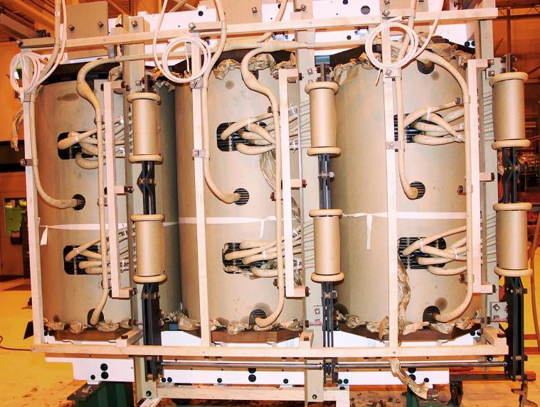
10 De-Energized Tap Changers SPX Transformer Solutions, Inc. September 4,
 Load loses are higher Stray I2R")


11 De-Energized Tap Changers Short circuit forces are higher More turns (5%) Load loses are higher Stray I2R Tank may be larger Core window is larger Winding to Tank Clearance for 1050KV BIL HV with DETC is greater than Winding to Tank Clearance for 1175KV BIL HV without DETC. SPX Transformer Solutions, Inc. September 4,
12 Voltage Regulation
13 Voltage Regulation Vin Source Vin = 100%V (e.g. 230KV) Load Vout Vout = 95%V (e.g KV) Factors Effecting Voltage Regulation Impedance Losses Load/Demand Increase in load/demand means drop in Vout Load Power Factor Decrease in load power factor means drop in Vout SPX Transformer Solutions, Inc. September 4,
14 Voltage Regulation The exact formula for calculating Regulation are as follows: When the loading is lagging: Per Unit regulation = (R + F P ) 2 +(X + q) 2 1 When the loading is leading: Per Unit regulation = (R + F P ) 2 +(X q) 2 1 where: F P is Per Unit load power factor 2 q is Per Unit 1 F P R is Per Unit Resistance = Z is Per Unit Impedance = X is Per Unit Reactance = Z 2 R 2 kw Load Loss kva Transformer Rating kva Impedance kva Transformer Rating Voltage Regulation IEEE C SPX Transformer Solutions, Inc. September 4,
15 Voltage Regulation 18/24/30 MVA Transformer Load Losses = MVA; Z = 18 MVA base = MVA, Z = 30 MVA base 18 MVA 30 MVA Power Factor % Regulation Power Factor % Regulation /24/30 MVA Transformer Load Losses = 18 MVA; Z = 18 MVA base = MVA, Z = 30 MVA base 18 MVA 30 MVA Power Factor % Regulation Power Factor % Regulation (> 10% LTC) Impedance Effects on Voltage Regulation SPX Transformer Solutions, Inc. September 4,
16 Voltage Regulation Regulators Power Factor Correction Load Tap Changers (LTCs) SPX Transformer Solutions, Inc. September 4,
17 Load Tap Changers
18 Load Tap Changers 90% of rated turns 100% of rated turns 90% of rated turns 10% of rated turns 20% of rated turns 32 Taps 10% of rated turns 16 Taps 10% of rated turns 16 Taps LINEAR PLUS/MINUS COARSE/FINE LTC Operating Principles SPX Transformer Solutions, Inc. September 4,
19 Load Tap Changers Rated Current (IEEE Std) Reduced Capacity Full Capacity Load Tap Changer Nameplates SPX Transformer Solutions, Inc. September 4,
20 Load Tap Changers 12,595Y/7272 Volts ( + 1%) 12,627Y/7290 Volts (+1.125%) 12,548Y/7245 Volts 12,470Y/7200 Volts 12,345Y/7128 Volts ( - 1%) LTC Control Operation SPX Transformer Solutions, Inc. September 4,

21 Load Tap Changers Multi Start Winding Tapped Winding Regulating Voltage Winding Design SPX Transformer Solutions, Inc. September 4,

22 Load Tap Changers LTC Lead Connections Multi Start Windings SPX Transformer Solutions, Inc. September 4,
23 Load Tap Changers Resistance: European design High Speed Transition impedance is a resistor, bridging operation Reactance: United States LTC development Reactance transition impedance inserted into the tap circuit to limit circulating current (Preventive Autotransformer) Vacuum Interrupters introduced 1960s Two Basic Types SPX Transformer Solutions, Inc. September 4,
24 Load Tap Changers Resistance LTC Reactance LTC SPX Transformer Solutions, Inc. September 4,
25 Load Tap Changers Reactance Type LTC With Vacuum Interrupter SPX Transformer Solutions, Inc. September 4,
 taps")

26 Load Tap Changers Preventive Auto Transformers Gaped Core, Operates saturated Fully excited only in odd positions High sound level in all odd (bridging positions) taps Rating 1.25% of main unit, full current, 1.25% voltage 50 MVA transformer, Preventive Auto is rated 625 kva Reactance Bridge SPX Transformer Solutions, Inc. September 4,


27 Load Tap Changers VIDEOS Reversing Switch, Stationary & Moving Contacts Spring Drive Resistance Bridging UZD LTC SPX Transformer Solutions, Inc. September 4,
28 Load Tap Changers Reactive Type - RMVII Resistive Type - UZDVac L L Resistive Type - UZD SPX Transformer Solutions, Inc. September 4,
 Regulating winding (4140 V and 200 amp) 250 V LTC rating 600 A 1200 A Load, 1200 amp Reversing switch 200A 1200A Series Transformer, 6:1 ratio FIGURE 7 SERIES")
29 Load Tap Changers Used to reduce the current through the load tap changer where load current exceeds the current rating LTC Can be used to reduce voltage level at the load tap changer Supply Primary winding Secondary winding (1200 amp) Regulating winding (4140 V and 200 amp) 250 V LTC rating 600 A 1200 A Load, 1200 amp Reversing switch 200A 1200A Series Transformer, 6:1 ratio FIGURE 7 SERIES TRANSFORMER APPLICATION Booster/Series Transformers SPX Transformer Solutions, Inc. September 4,

30 Load Tap Changers Booster/Series Transformer SPX Transformer Solutions, Inc. September 4,
31 LTC Application Considerations
32 LTC Application Considerations CFVV (Constant Flux Voltage Variation) Impedance is Constant Sound Level is Constant Step Voltage is Constant VFVV (Variable Flux Voltage Variation) Impedance is Variable Sound Level is Variable Step Voltage is Variable Power Transformer CFVV and VFVV Comparison LTC Position P.U. Impedance P.U. Voltage CFVV VFVV CFVV VFVV 16R N L Application Considerations CFVV vs VFVV SPX Transformer Solutions, Inc. September 4,
33 LTC Application Considerations CFVV (Constant Flux Voltage Variation) 230KV LOAD V/T remains constant Number of turns changes, therefore voltage changes SPX Transformer Solutions, Inc. September 4,
34 LTC Application Considerations VFVV (Variable Flux Voltage Variation) 230KV LOAD V/T changes: Supply voltage remains constant Number of turns changes Since V/T changes, voltage changes SPX Transformer Solutions, Inc. September 4,
35 LTC Application Considerations Power Transformer Installation in neutral end of a wye winding CFVV Installation in HV winding to regulate the LV VFVV Installation in HV winding to regulate HV winding CFVV Autotransformer Installation in neutral VFVV Installation in XV line CFVV Installation in common end of HV series winding to regulate HV CFVV Installation in common end of HV series winding to regulate LV VFVV Application Considerations CFVV vs VFVV SPX Transformer Solutions, Inc. September 4,


36 LTC Application Considerations ABB UZ Series ABB VRLTC Reinhausen RMV-II Waukesha UZD Waukesha UZDVac On Tank Load Tap Changers SPX Transformer Solutions, Inc. September 4,


37 LTC Application Considerations ABB UC Series Reinhausen VACUTAP VR Series In Tank Load Tap Changers SPX Transformer Solutions, Inc. September 4,
38 Paralleling
39 Paralleling Where: Z A, Z B = Per Unit Impedance of transformers A and B I A, I B = Per Unit Load current of transformers A and B I L = Per Unit Load current of transformer A and B in parallel Assuming the voltage drop through both transformers is equal Then: I A x Z A = I B x Z B and I L = I A + I B Solving these equations, we get the following load distribution between the two transformers I A = Z B Z A + Z B and I B = Z A Z A + Z B Design for Transformer Parallel Operation SPX Transformer Solutions, Inc. September 4,
40 Paralleling Given / Known Bank A 10/12.5 MVA Impedance 0.08 per unit at 10 MVA base Bank B 12/16/20 MVA Impedance 0.08 per unit at 12 MVA base Step 1 Bank A Bank B per unit at 12.5 MVA base per unit at 12.5 MVA base Step 2 Bank A loading = Bank B loading = Z B Z A + Z B = Z A Z A + Z B = = per unit load = per unit load Step 3 The maximum total load of Bank A and B paralleled without overloading Bank A is 12.5 = 27.5 MVA Therefore, the maximum loading of Bank B without overloading Bank A is = 15.0 MVA (less than the 20 MVA rating of Bank B transformer). Parallel Operation Case I Different Cooling Classes SPX Transformer Solutions, Inc. September 4,
41 Paralleling Given / Known Bank A impedance = 0.16 per unit at 20 MVA base, the top rating of the proposed new transformer. Anticipated total load = 32.5 MVA Step 1 Bank A rated per unit load capacity of 12.5 MVA is paralleled bank loading of 32.5 MVA. = per unit of the Bank B rated load capacity of 20 MVA is 20.0 = per unit of the paralleled 32.5 bank loading of 32.5 MVA. Bank B impedance needs to be calculated to carry per unit of the bank capacity. Step 2 Bank B loading of per unit = Z A Z A + Z B = X solving for X. X = 0.10 per unit on 20 MVA base. Converting to a 12 MVA base, the impedance needs to be per unit on the self cooled nameplate rating of 12 MVA. Parallel Operation Case II Different Cooling Classes SPX Transformer Solutions, Inc. September 4,
42 Paralleling If the transformers are both rated with two identical stages of cooling and both have identical impedances on their self cooled based, each transformer will share load according to it s rating: Bank A 12/16/20 MVA Impedance 0.08 per unit at 10 MVA base Bank B 24/32/40 MVA Impedance 0.08 per unit at 24 MVA base First state the per unit impedance of each bank on the same MVA base: Bank A per unit on 40 MVA base Bank B per unit on 40 MVA base The transformers share load inversely to the ratio of the impedance of the bank to the sum of the impedances of the banks in parallel. Bank A load share = Bank B load share = Z B Z A + Z B = Z A Z A + Z B = = per unit load = per unit load This validates that transformers of equal per unit impedance (expressed on their own MVA base) will share load proportionate to their ratings. Parallel Operation Case III Same Cooling Classes, Different Ratings SPX Transformer Solutions, Inc. September 4,
43 Questions? Thank you!
Regional Technical Seminar
 Regional Technical Seminar LOAD TAP CHANGERS (LTCS) DESIGN, OPERATION, AND MAINTENANCE CONSIDERATIONS SPX Dallas Facility Damon Jones General Manager SPX Transformer Solutions Components Group Cell: 214-422-8979
Load Tap Changers for Power Transformers
 Load Tap Changers for Power Transformers Dr. Dieter Dohnal / Maschinenfabrik Reinhausen GmbH Dipl. Ing. Bernhard Kurth / Reinhausen Manufacturing Inc. Load Tap Changers for Power Transformers Content Basic
Transformer Winding Design. The Design and Performance of Circular Disc, Helical and Layer Windings for Power Transformer Applications
 The Design and Performance of Circular Disc, Helical and Layer Windings for Power Transformer Applications Minnesota Power Systems Conference November 3 5, 2009 Earl Brown Heritage Center University of
Electrical Design Process
 Electrical Design Process Jason Varnell Lead Design Engineer Jason.Varnell@spx.com SPX Transformer Solutions, Inc. September 26, 2018 Agenda 1. Bid Design Process Parameters Affecting Bid Design 2. Final
GENERATOR INTERCONNECTION APPLICATION Category 5 For All Projects with Aggregate Generator Output of More Than 2 MW
 GENERATOR INTERCONNECTION APPLICATION Category 5 For All Projects with Aggregate Generator Output of More Than 2 MW ELECTRIC UTILITY CONTACT INFORMATION Consumers Energy Interconnection Coordinator 1945
Understanding and Extracting Valuable Information from Basic and Advanced Power Transformer Testing Techniques
 Understanding and Extracting Valuable Information from Basic and Advanced Power Transformer Testing Techniques Charles Sweetser, Services Manager, PRIM Engineering, Waltham, Mass. Topics of Discussion
Regional Technical Seminar SHORT CIRCUIT FORCES
 Regional Technical Seminar SHORT CIRCUIT FORCES Short Circuit Forces Wallace Exum Electrical Design Engineer wallace.exum@spx.com Agenda 1. What is Short Circuit 2. Types of Faults 3. How to Calculate
Transformer Factory Testing
 Transformer Factory Testing John J. Foschia Test Engineer John.Foschia@spx.com September 2018 Reasons for Testing Compliance with user specifications Assessment of quality and reliability Verification
TesTIng of Power. Transformers are the largest, most. feature. By brandon dupuis
 feature By brandon dupuis An Introduction to Electrical diagnostic TesTIng of Power Transformers 38 Transformers are the largest, most expensive, and highly critical components of most utility substations.
148 Electric Machines
 148 Electric Machines 3.1 The emf per turn for a single-phase 2200/220- V, 50-Hz transformer is approximately 12 V. Calculate (a) the number of primary and secondary turns, and (b) the net cross-sectional
86 chapter 2 Transformers
 86 chapter 2 Transformers Wb 1.2x10 3 0 1/60 2/60 3/60 4/60 5/60 6/60 t (sec) 1.2x10 3 FIGURE P2.2 2.3 A single-phase transformer has 800 turns on the primary winding and 400 turns on the secondary winding.
Chapter 2: Transformers
 Chapter 2: Transformers 2-1. The secondary winding of a transformer has a terminal voltage of v s (t) = 282.8 sin 377t V. The turns ratio of the transformer is 100:200 (a = 0.50). If the secondary current
GENERATOR INTERCONNECTION APPLICATION FOR ALL PROJECTS WITH AGGREGATE GENERATOR OUTPUT OF MORE THAN 2 MW
 GENERATOR INTERCONNECTION APPLICATION FOR ALL PROJECTS WITH AGGREGATE GENERATOR OUTPUT OF MORE THAN 2 MW Electric Utility Contact Information DTE Energy Interconnection Coordinator One Energy Plaza, SB
Understanding the Value of Electrical Testing for Power Transformers. Charles Sweetser - OMICRON
 Understanding the Value of Electrical Testing for Power Transformers Charles Sweetser - OMICRON Transformers Diagnostic Testing - OVERALL DGA Oil Screen Power Factor / Capacitance Exciting Current Transformer
Regional Technical Seminar SHORT CIRCUIT FORCES
 Regional Technical Seminar SHORT CIRCUIT FORCES Douglas W Reed Principal Electrical Design Engineer douglas.reed@spx.com SPX Transformer Solutions, Inc. June 20th, 2018 Agenda 1.Review transformers: How
Pomona, CA May 24 & 25, LTC Applications - Location, Series & Preventative Auto Transformers
 Pomona, CA May 24 & 25, 2016 LTC Applications - Location, Series & Preventative Auto s siemens.com/answers Introduction Tap changer at active part Example of 3-phase tapchanger Page 2 Winding Configurations
KNOW MORE ABOUT THE TRANSFORMERS. Glossary Transformers
 KNOW MORE ABOUT THE TRANSFORMERS Glossary Transformers Ambient temperature The existing temperature of the atmosphere surrounding a transformer installation. Ampere The practical unit of electric current.
Power Measurements and Basic Electrical Diagnostic Tests
 Power Measurements and Basic Electrical Diagnostic Tests Instrument Basics Burden VA Sources V and I Meters V and I KVL and KCL Kelvin Connection KVL and KCL Kelvin Connection 4-Wire Technique Exclude
Phase Shifting Transformers. Presented by
 Phase Shifting Transformers Presented by Phase Shifting Transformers (PST s) (a.k.a. Phase Angle Regulators) VS φ S P V V S = X L L X L sin( φ φ ) L S VL φ L PST s are power flow control devices between
Training Fees 3,300$ per participant including Materials/Handouts, Tea/Coffee Refreshments & International Buffet Lunch.
 Training Title POWER TRANSFORMERS Training Duration 5 days Training Venue and Dates Power transformers 5 20-24 May $3,300 Abu Dhabi In any of the 5 star hotel. The exact venue will be informed soon. Training
Power Transformers Basics
 Power Transformers Basics Transformer Basic Objective Introduce Basic Transformer Theory as it Relates to Diagnostics Provide a Better Understanding of the Diagnostic Test Environment Identify Important
PROBLEMS on Transformers
 PROBLEMS on Transformers (A) Simple Problems 1. A single-phase, 250-kVA, 11-kV/415-V, 50-Hz transformer has 80 turns on the secondary. Calculate (a) the approximate values of the primary and secondary
CHAPTER 4. Distribution Transformers
 CHAPTER 4 Distribution Transformers Introduction A transformer is an electrical device that transfers energy from one circuit to another purely by magnetic coupling. Relative motion of the parts of the
PES & IAS NY Chapter And NY LMAG June 23 rd, 2015
 PES & IAS NY Chapter And NY LMAG June 23 rd, 2015 High Temperature Insulation Systems and their use in Mobile Transformers Myron B. Bell, PE mbell@deltastar.com Delta Star, Inc. June 23 rd 2015 Introduction
Curve accuracy (enough data points to be statistically significant): See Attachment B.
: See Attachment B.") Curve accuracy (enough data points to be statistically significant): See Attachment B. /11.0 proposals Mar 2006.doc /11.0 proposals Mar 2006.doc ATTACHMENT A New Business By Subhash Tuli Waukesha Electric
Curve accuracy (enough data points to be statistically significant): See Attachment B. /11.0 proposals Mar 2006.doc /11.0 proposals Mar 2006.doc ATTACHMENT A New Business By Subhash Tuli Waukesha Electric
Effects of Harmonic Distortion I
 Effects of Harmonic Distortion I Harmonic currents produced by nonlinear loads are injected back into the supply systems. These currents can interact adversely with a wide range of power system equipment,
The measurement of winding resistance is useful in detecting a number of types of fault in a transformer. Malfunctioning tap changer mechanisms
 Why Measure Winding Resistance? The measurement of winding resistance is useful in detecting a number of types of fault in a transformer. Malfunctioning tap changer mechanisms Partial or dead short-circuited
TRANSFORMER THEORY. Mutual Induction
 Transformers Transformers are used extensively for AC power transmissions and for various control and indication circuits. Knowledge of the basic theory of how these components operate is necessary to
Understanding the Value of Electrical Testing for Power Transformers. Charles Sweetser, OMICRON electronics Corp. USA
 Understanding the Value of Electrical Testing for Power Transformers Charles Sweetser, OMICRON electronics Corp. USA Understanding the Value of Electrical Testing for Power Transformers Charles Sweetser,
Impact Assessment Generator Form
 Impact Assessment Generator Form This connection impact assessment form provides information for the Connection Assessment and Connection Cost Estimate. Date: (dd/mm/yyyy) Consultant/Developer Name: Project
S. C. Electric Cooperative s Specification for a Single-Phase, Single Bushing Overhead Distribution Transformer (Revised 10/2013)
") S. C. Electric Cooperative s Specification for a Single-Phase, Single Bushing Overhead Distribution Transformer (Revised 10/2013) 1.0 GENERAL 1.1 This specification covers the electrical and mechanical
S. C. Electric Cooperative s Specification for a Single-Phase, Single Bushing Overhead Distribution Transformer (Revised 10/2013) 1.0 GENERAL 1.1 This specification covers the electrical and mechanical
Module 7. Transformer. Version 2 EE IIT, Kharagpur
 Module 7 Transformer Lesson 28 Problem solving on Transformers Contents 28 Problem solving on Transformer (Lesson-28) 4 28.1 Introduction. 4 28.2 Problems on 2 winding single phase transformers. 4 28.3
APPENDIX 1 to LGIP INTERCONNECTION REQUEST FOR A LARGE GENERATING FACILITY
 APPENDIX 1 to LGIP INTERCONNECTION REQUEST FOR A LARGE GENERATING FACILITY 1. The undersigned Interconnection Customer submits this request to interconnect its Large Generating Facility with Transmission
FIELD ELECTRICAL TESTING SPX TRANSFORMER SOLUTIONS, INC.
 Regional Technical Seminar FIELD ELECTRICAL TESTING SPX TRANSFORMER SOLUTIONS, INC. Field Electrical Testing Applications Key Purposes of Field Electrical Testing: Receiving inspection Acceptance testing/commissioning
Transformer Technology Seminar Winding Selection
 Pomona, CA May 24 25, 2016 Transformer Technology Seminar Siemens AG Transformers siemens.com/answers Windings: Page 2 Example GSU 274/464MVA H0 H1 H2 H3 U U I I H L H L N = N N = N L H H L HV: 405kV ±8x1.25%
PCS Working Group on General Requirements C
 WG Item 82 C57.12.00-2000 Section 7.1.4.4 Stabilizing windings Change Requested by : V. Sankar 5/07/2005 & 10/23/2006 Requested Change : Request to form a task force to discuss the following on buried
ENGINEERING DATA SUBMITTAL For the Interconnection of Generation System
 WHO SHOULD FILE THIS SUBMITTAL: Anyone in the final stages of interconnecting a Generation System with Nodak Electric Cooperative, Inc. This submittal shall be completed and provided to Nodak Electric
IDAHO PURPA GENERATOR INTERCONNECTION REQUEST (Application Form)
") IDAHO PURPA GENERATOR INTERCONNECTION REQUEST (Application Form) Transmission Provider: IDAHO POWER COMPANY Designated Contact Person: Jeremiah Creason Address: 1221 W. Idaho Street, Boise ID 83702 Telephone
IDAHO PURPA GENERATOR INTERCONNECTION REQUEST (Application Form) Transmission Provider: IDAHO POWER COMPANY Designated Contact Person: Jeremiah Creason Address: 1221 W. Idaho Street, Boise ID 83702 Telephone
Transformer Protection Principles
 Transformer Protection Principles 1. Introduction Transformers are a critical and expensive component of the power system. Due to the long lead time for repair of and replacement of transformers, a major
Component Requirement Specification for SGI 500XT Isolation Transformer
 REVISION CONTROL REV. DESCRIPTION DATE APPROVED A Initial release 01/21/13 M.Hale B Allowance f low voltage Wye w/ insulated neutral. 04/10/13 M.Hale C Secondary Configuration added. Added Primary Configuration
PROCEDURE. Part 3.5: Site-Specific Loss Adjustments PUBLIC. Market Manual 3: Metering. Issue 8.0 MDP_PRO_0011
 PUBLIC MDP_PRO_0011 PROCEDURE Market Manual 3: Metering Part 3.5: Site-Specific Loss Adjustments Issue 8.0 This document provides guidance to metering service providers on how to calculate and submit Site-Specific
MR PUBLICATION. On-Load Tap-Changers for Power Transformers A Technical Digest
 On-Load Tap-Changers for Power Transformers A Technical Digest Abstract Introduction On-Load Tap-Changers (OLTCs) are one of the indispensable components for the regulation of power transformers used
Transformers. 4.1 Basics
 4 Transformers Ac transformers are one of the keys to allowing widespread distribution of electric power as we see it today. Transformers efficiently convert electricity to higher voltage for long distance
Cork Institute of Technology. Autumn 2008 Electrical Energy Systems (Time: 3 Hours)
") Cork Institute of Technology Bachelor of Science (Honours) in Electrical Power Systems - Award Instructions Answer FIVE questions. (EELPS_8_Y4) Autumn 2008 Electrical Energy Systems (Time: 3 Hours) Examiners:
Cork Institute of Technology Bachelor of Science (Honours) in Electrical Power Systems - Award Instructions Answer FIVE questions. (EELPS_8_Y4) Autumn 2008 Electrical Energy Systems (Time: 3 Hours) Examiners:
MGM Transformer. Vacuum Pressure Impregnated (VPI) Dry-Type Substation Transformer Specification Guide
 Dry-Type Substation Transformer Specification Guide") MGM Transformer Vacuum Pressure Impregnated (VPI) Dry-Type Substation Transformer Specification Guide MGM Transformer Company 5701 Smithway Street Commerce, CA 90040 www.mgmtransformer.com Phone: 323.726.0888
MGM Transformer Vacuum Pressure Impregnated (VPI) Dry-Type Substation Transformer Specification Guide MGM Transformer Company 5701 Smithway Street Commerce, CA 90040 www.mgmtransformer.com Phone: 323.726.0888
INTERCONNECTION REQUEST FOR A LARGE GENERATING FACILITY
 INTERCONNECTION REQUEST FOR A LARGE GENERATING FACILITY Internal Use Only Date Received Time Received Received By: 1. The undersigned Interconnection Customer submits this request to interconnect its Large
Embedded Generation Connection Application Form
 Embedded Generation Connection Application Form This Application Form provides information required for an initial assessment of the Embedded Generation project. All applicable sections must be completed
SECTION 4 TRANSFORMERS. Yilu (Ellen) Liu. Associate Professor Electrical Engineering Department Virginia Tech University
 Liu. Associate Professor Electrical Engineering Department Virginia Tech University") SECTION 4 TRANSFORMERS Yilu (Ellen) Liu Associate Professor Electrical Engineering Department Virginia Tech University Analysis of Transformer Turns Ratio......................... 4.2 Analysis of a Step-Up
SECTION 4 TRANSFORMERS Yilu (Ellen) Liu Associate Professor Electrical Engineering Department Virginia Tech University Analysis of Transformer Turns Ratio......................... 4.2 Analysis of a Step-Up
TRANSFORMERS PART A. 2. What is the turns ratio and transformer ratio of transformer? Turns ratio = N2/ N1 Transformer = E2/E1 = I1/ I2 =K
 UNIT II TRANSFORMERS PART A 1. Define a transformer? A transformer is a static device which changes the alternating voltage from one level to another. 2. What is the turns ratio and transformer ratio of
Single-Phase Transformation Review
 Single-Phase Transformation Review S T U D E N T M A N U A L March 2, 2005 2 STUDENT TRAINING MANUAL Prerequisites: None Objectives: Given the Construction Standards manual and a formula sheet, you will
Short-Circuit Current Calculations
 Basic Point-to-Point Calculation Procedure Step. Determine the transformer full load amps (F.L.A.) from either the nameplate, the following formulas or Table : Multiplier = 00 *% Z transformer Step 2.
~=E.i!=h. Pre-certification Transformers
 7 Transformers Section 26 of the electrical code governs the use and installations of transformers. A transformer is a static device used to transfer energy from one alternating current circuit to another.
Tatjana Šimović a *, Marko Stanić a, Laurenc Kirchner b
 4 th International Colloquium "Transformer Research and Asset Management" Pula, Croatia, May 10 12, 2017 200 MVA phase shifting autotransformer for HE Senj and the possibility to change-over between active
TRANSFORMER OPERATION
 Chapter 3 TRANSFORMER OPERATION 1 A transformer is a static device (no moving parts) used to transfer energy from one AC circuit to another. This transfer of energy may involve an increase or decrease
Experiment 45. Three-Phase Circuits. G 1. a. Using your Power Supply and AC Voltmeter connect the circuit shown OBJECTIVE
 Experiment 45 Three-Phase Circuits OBJECTIVE To study the relationship between voltage and current in three-phase circuits. To learn how to make delta and wye connections. To calculate the power in three-phase
Initial Application Form for Connection of Distributed Generation (>10kW)
") Please complete the following information and forward to Vector Contact Details Primary Contact (who we should contact for additional information) Contact person Company name Contact numbers Daytime: Cell
Please complete the following information and forward to Vector Contact Details Primary Contact (who we should contact for additional information) Contact person Company name Contact numbers Daytime: Cell
Practical Transformer on Load
 Practical Transformer on Load We now consider the deviations from the last two ideality conditions : 1. The resistance of its windings is zero. 2. There is no leakage flux. The effects of these deviations
Back to the Basics Current Transformer (CT) Testing
 Testing") Back to the Basics Current Transformer (CT) Testing As test equipment becomes more sophisticated with better features and accuracy, we risk turning our field personnel into test set operators instead of
Back to the Basics Current Transformer (CT) Testing As test equipment becomes more sophisticated with better features and accuracy, we risk turning our field personnel into test set operators instead of
Differential Protection with REF 542plus Feeder Terminal
 Differential Protection with REF 542plus Application and Setting Guide kansikuva_bw 1MRS 756281 Issued: 09.01.2007 Version: A Differential Protection with REF 542plus Application and Setting Guide Contents:
POWER TRANSFORMER SPECIFICATION, DESIGN, QUALITY CONTROL AND TESTING 18 MARCH 2009
 POWER TRANSFORMER SPECIFICATION, DESIGN, QUALITY CONTROL AND TESTING 18 MARCH 2009 Nkosinathi Buthelezi Senior Consultant: Power Transformers and Reactors Presentation Content Standardization of Power
Liquid-Filled Transformers
 Liquid-Filled Transformers Custom Transformers at Standard Prices NIAGARA TRANSFORMER CORP. Induction Furnace Transformer Cycloconverter Rectifier Duty Transformer Arc Furnace Transformer Full Range of
CONSULTANT PROCEDURES & DESIGN GUIDELINES Liquid-Filled Utility Transformers UNIVERSITY OF MISSOURI
 GENERAL: The scope of this document is to provide instruction for the installation and testing of Medium Voltage, 3 Phase, Pad Mounted Transformers installed at the University of Missouri. Preferred transformers
Hours / 100 Marks Seat No.
 17415 15162 3 Hours / 100 Seat No. Instructions (1) All Questions are Compulsory. (2) Answer each next main Question on a new page. (3) Illustrate your answers with neat sketches wherever necessary. (4)
Type KLF Generator Field Protection-Loss of Field Relay
 Supersedes DB 41-745B pages 1-4, dated June, 1989 Mailed to: E, D, C/41-700A ABB Power T&D Company Inc. Relay Division Coral Springs, FL Allentown, PA For Use With Delta Connected Potential Transformers
Transformer & Induction M/C
 UNIT- 2 SINGLE-PHASE TRANSFORMERS 1. Draw equivalent circuit of a single phase transformer referring the primary side quantities to secondary and explain? (July/Aug - 2012) (Dec 2012) (June/July 2014)
Power Transformer Ratings' Calculation and Analysis - IEEE C
 Power Transformer Ratings' Calculation and Analysis - IEEE C57.91-1995 Course No. E-3058 Credit: 3 PDH 2017 Decatur Professional Development, LLC. All rights reserved. Power Transformer Ratings Calculation
MAHARASHTRA STATE BOARD OF TECHNICAL EDUCATION
 Important Instructions to examiners: 1) The answers should be examined by key words and not as word-to-word as given in the model answer scheme. 2) The model answer and the answer written by candidate
Phase Shifter Application Workshop. Siemens Energy, Inc.
 Phase Shifter Application Workshop Siemens Energy, Inc. PJM Power Pool, March, 2015 siemens.com/energy Phase Shifter Application Workshop Phase Shifting Transformers Principles, Design Aspects and Operation
Modeling of Three-phase or Bank of Three Single Phase Three Winding Transformers Zero-phase-sequence Leakage Impedance in PSS E Short Circuit Module
 Siemens Industry, Inc. Power Technology Issue 125 Modeling of Three-phase or Bank of Three Single Phase Three Winding Transformers Zero-phase-sequence Leakage Impedance in PSS E Short Circuit Module Carlos
MAHARASHTRA STATE BOARD OF TECHNICAL EDUCATION
 Important Instructions to examiners: 1) The answers should be examined by key words and not as word-to-word as given in the model answer scheme. 2) The model answer and the answer written by candidate
SPECIFICATION FOR STEP UP TRANSFORMER 0.415/11Kv and (630KVA & 1000KVA)
") SPECIFICATION FOR STEP UP TRANSFORMER 0.415/11Kv and (630KVA & 1000KVA) 0.415/33kV DESIGN AND CONSTRUCTION General 1. The transformer shall be three phase, oil immersed type, air cooled, core type, outdoor
SPECIFICATION FOR STEP UP TRANSFORMER 0.415/11Kv and (630KVA & 1000KVA) 0.415/33kV DESIGN AND CONSTRUCTION General 1. The transformer shall be three phase, oil immersed type, air cooled, core type, outdoor
NORTH CAROLINA INTERCONNECTION REQUEST. Utility: Designated Contact Person: Address: Telephone Number: Address:
 NORTH CAROLINA INTERCONNECTION REQUEST Utility: Designated Contact Person: Address: Telephone Number: Fax: E-Mail Address: An is considered complete when it provides all applicable and correct information
Numbering System for Protective Devices, Control and Indication Devices for Power Systems
 Appendix C Numbering System for Protective Devices, Control and Indication Devices for Power Systems C.1 APPLICATION OF PROTECTIVE RELAYS, CONTROL AND ALARM DEVICES FOR POWER SYSTEM CIRCUITS The requirements
ECG 741 Power Distribution Transformers. Y. Baghzouz Spring 2014
 ECG 741 Power Distribution Transformers Y. Baghzouz Spring 2014 Preliminary Considerations A transformer is a device that converts one AC voltage to another AC voltage at the same frequency. The windings
Technical guide. Type VRLTC load tap changer
 Technical guide Type VRLTC load tap changer Table of contents General information... 2 Electrical characteristics... 3 Type tests... 4 Switching sequence... 5 Tank characteristics... 7 Terminal board...
Introduction : Design detailed: DC Machines Calculation of Armature main Dimensions and flux for pole. Design of Armature Winding & Core.
 Introduction : Design detailed: DC Machines Calculation of Armature main Dimensions and flux for pole. Design of Armature Winding & Core. Design of Shunt Field & Series Field Windings. Design detailed:
On-load tap-changer VACUTAP VRD, VRF, VRG
 www.reinhausen.com On-load tap-changer VACUTAP VRD, VRF, VRG Technical Data TD 237/02 Table of Contents Table of Contents 1 General / Technical data... 3 1.1 On-load tap-changer designations... 3 1.2 Summary
INSTITUTE OF AERONAUTICAL ENGINEERING (Autonomous) Dundigal, Hyderabad
 Dundigal, Hyderabad") INSTITUTE OF AERONAUTICAL ENGINEERING (Autonomous) Dundigal, Hyderabad - 00 03 ELECTRICAL AND ELECTRONICS ENGINEERING ASSIGNMENT Course Name : ELECRICAL MACHINES - II Course Code : A0 Class : II B.TECH-II
INSTITUTE OF AERONAUTICAL ENGINEERING (Autonomous) Dundigal, Hyderabad - 00 03 ELECTRICAL AND ELECTRONICS ENGINEERING ASSIGNMENT Course Name : ELECRICAL MACHINES - II Course Code : A0 Class : II B.TECH-II
Spring 2000 EE361: MIDTERM EXAM 1
 NAME: STUDENT NUMBER: Spring 2000 EE361: MIDTERM EXAM 1 This exam is open book and closed notes. Assume f=60 hz and use the constant µ o =4π 10-7 wherever necessary. Be sure to show all work clearly. 1.
Power Flow Redistribution in Croatian Power System Network using Phase- Shifting Transformer
 Power Flow Redistribution in Croatian Power System Network using Phase- Shifting Transformer Ivica Pavić Faculty of Electrical Engineering and Computing Zagreb, CROATIA Sejid Tešnjak Faculty of Electrical
Generation Interconnection Study Data Sheet Synchronous Machines
 FOR INTERNAL USE ONLY GTC Project Number: Queue Date: Generation Interconnection Study Data Sheet Synchronous Machines Customers must provide the following information in its entirety. GTC will not proceed
Tertiary Winding Design in wye-wye Connected Transformers Restricted Siemens Energy 2013 All rights reserved.
 Pomona, CA, May 24 & 25, 2016 Tertiary Winding Design in wye-wye Connected Transformers Scope of Presentation > Tertiary vs. Stabilizing Winding? Tertiary vs. Stabilizing Winding? Need for Stabilizing
Technical guide. Type VRLTC load tap changer
 Technical guide Type VRLTC load tap changer Table of contents 2 General information 4 Switching sequences 6 Tank characteristics 6 Terminal board 7 Tap selector 7 Stationary contacts 7 Reversing switch
Embedded Generation Connection Application Form
 Embedded Generation Connection Application Form This Application Form provides information required for an initial assessment of the Embedded Generation project. All applicable sections must be completed
Owner/Customer Name: Mailing Address: City: County: State: Zip Code: Phone Number: Representative: Address: Fax Number:
 Interconnection of a Customer-Owned Renewable Generation System of Greater than 100 KW and Less than or Equal to 1 MW to the LCEC Electric Grid Tier 3 Application and Compliance Form Instructions: Complete
UNIVERSITY OF MISSOURI Liquid-Filled Utility Transformers 2016 Q1
 GENERAL: The scope of this document is to provide instruction for the installation and testing of Medium Voltage, 3 Phase, Pad Mounted Transformers installed at the University of Missouri. Preferred transformers
ADVANCES IN INDUSTRIAL SUBSTATION DESIGN USING THREE WINDING POWER TRANSFORMERS
 ADVANCES IN INDUSTRIAL SUBSTATION DESIGN USING TREE WINDING POWER TRANSFORMERS Copyright Material IEEE Paper No. PCIC-2008-XX Doug Brooks P.Eng Don Morency P.Eng. Pascal Tang P.Eng Senior Member, IEEE
The power transformer
 ELEC0014 - Introduction to power and energy systems The power transformer Thierry Van Cutsem t.vancutsem@ulg.ac.be www.montefiore.ulg.ac.be/~vct November 2017 1 / 35 Power transformers are used: to transmit
On-load tap-changer VACUTAP VRC and VRE
 www.reinhausen.com On-load tap-changer VACUTAP VRC and VRE Technical Data TD 246/03 Table of Contents Table of Contents 1 General / Technical data... 4 1.1 On-load tap-changer designations... 4 1.2 Summary
Rarely used, problems with unbalanced loads.
 THREE-PHASE TRANSFORMERS Transformers used in three-phase systems may consist of a bank of three single-phase transformers or a single three-phase transformer which is wound on a common magnetic core.
UNIVERSITY OF TECHNOLOGY By: Fadhil A. Hasan ELECTRICAL MACHINES
 UNIVERSITY OF TECHNOLOGY DEPARTMENT OF ELECTRICAL ENGINEERING Year: Second 2016-2017 By: Fadhil A. Hasan ELECTRICAL MACHINES І Module-II: AC Transformers o Single phase transformers o Three-phase transformers
EN Assignment No.1 - TRANSFORMERS
 EN-06 - Assignment No.1 - TRANSFORMERS Date : 13 th Jan 01 Q1) A 0kVA 00/0 Volts, 60Hz, single phase transformer is found to have the following equivalent circuit parameter referred to the high potential
SYNCHRONOUS MACHINES
 SYNCHRONOUS MACHINES The geometry of a synchronous machine is quite similar to that of the induction machine. The stator core and windings of a three-phase synchronous machine are practically identical
VACUTAP VVS COMPACT ON-LOAD TAP-CHANGER FOR GRID APPLICATIONS.
 COMPACT ON-LOAD TAP-CHANGER FOR GRID APPLICATIONS. WWW.REINHAUSEN.COM 2 TAILORED FOR GRID APPLICATIONS. The vacuum on-load tap-changer was developed and optimized for operation in transformers up to approximately
WESTERN UNDERGROUND COMMITTEE GUIDE 2.6 (2.6/00/0868)
") WESTERN UNDERGROUND COMMITTEE GUIDE 2.6 (2.6/00/0868) THREE-PHASE SUBSURFACE UNDERGROUND COMMERCIAL DISTRIBUTION (UCD) TRANSFORMER NOTE: This "Guide" summarizes the opinions, recommendations, and practices
WESTERN UNDERGROUND COMMITTEE GUIDE 2.6 (2.6/00/0868) THREE-PHASE SUBSURFACE UNDERGROUND COMMERCIAL DISTRIBUTION (UCD) TRANSFORMER NOTE: This "Guide" summarizes the opinions, recommendations, and practices
DATA SHEET FOR LIGHTING TRANSFORMER APPD. BY VDV PROJECT NO
 PART - A : SPECIFIC REQUIREMENTS THIS DATA SHEET IS APPLICABLE FOR IN BOILER A CLIMATIC CONDITIONS PACKAGE 1 DESIGN AMBIENT TEMPERATURE 45 C 2 ALTITUDE ( ABOVE MSL ) 6.71 MTRS. 3 RELATIVE HUMIDITY 74 %
ISSN: [IDSTM-18] Impact Factor: 5.164
![ISSN: [IDSTM-18] Impact Factor: 5.164](/thumbs/91/106796217.jpg "ISSN: [IDSTM-18] Impact Factor: 5.164") IJESRT INTERNATIONAL JOURNAL OF ENGINEERING SCIENCES & RESEARCH TECHNOLOGY A REVIEW OF ROUTINE TESTING ON DISTRIBUTION TRANSFORMER Sukhbir Singh 1, Parul Jangra 2, Anoop Bhagat 3, Vipin Saini 4 1 Assistant
IJESRT INTERNATIONAL JOURNAL OF ENGINEERING SCIENCES & RESEARCH TECHNOLOGY A REVIEW OF ROUTINE TESTING ON DISTRIBUTION TRANSFORMER Sukhbir Singh 1, Parul Jangra 2, Anoop Bhagat 3, Vipin Saini 4 1 Assistant
Ch.2 Solutions posted on web page, go thru them for review.
 EE 5200 - Lecture 5 Wed Sep 13, 2017 Topics for Today: Announcements Software: Matlab? Will begin using as early as next week. Office hrs: 2pm, M,W,F (will try this, can adjust if needed) Grader Office
(2) New Standard IEEE P (3) Core : (4) Windings :
 New Standard IEEE P (3) Core : (4) Windings :") (d) Electrical characteristics (such as short-circuit withstand, commutating reactance, more number of windings, etc); (e) Longer life expectancy; (f) Energy efficiency; (g) more demanding environment.
(d) Electrical characteristics (such as short-circuit withstand, commutating reactance, more number of windings, etc); (e) Longer life expectancy; (f) Energy efficiency; (g) more demanding environment.