THE AMAZING FET CIRCLOTRON
|
|
|
- Brice Barrett
- 5 years ago
- Views:
Transcription
1 THE AMAZING FET CIRCLOTRON 2008 Michael Rothacher Cue the Theremin music! This article is about building your own all-fet Circlotron. It smashes atoms. No, strike that. It won t smash atoms like a cyclotron, but it has a really cool name and it is, technically speaking, powered by atoms and very, very good at amplifying music. Circular Logic Alpha M. Wiggins of Electro-Voice is generally recognized as the inventor of the Circlotron amplifier although other inventors developed similar circuits around the same time period in the 1950 s. The Circlotron s transformer-coupled vacuum tube output circuit, a floating bridge, was often drawn in a circular fashion; hence the name. Later, Circlotron-type output stages were used to directly couple the output tubes to the loudspeaker and eliminate the need for an output transformer. At one time, Circlotron was an Electro-Voice (EV) trademark, but a cursory trademark search revealed that the name is no longer trademarked, and today the name Circlotron is applied to just about any amplifier with a floating bridge output stage. If you re a history buff, you may want to check out the Circlotron History Page. Circlotron circuits make for lots of interesting discussion among the audio crowd. They are sometimes thought to posses mystical powers and perform hitherto impossible quantum mechanical wonders. Oftentimes they re just confusing. More often than not, the discussion turns to intellectual property. A number of patents for Circlotron variants have been issued in the U.S. and many of them deal with biasing arrangements, voltage amplification stages, offset correction, and, and so on. Some of them are pretty novel. In any case, they make for great marketing. This article describes the design and construction of a fairly straightforward, simple Class A floating bridge amplifier, aka Circlotron. I hope, especially if you are new to this hobby, that you ll find this project simple and complete enough to actually build, even if it s your first. The Floating Bridge I use the terms Floating Bridge and Circlotron interchangeably and I believe that Floating Bridge more accurately describes the topology and makes for less hocus-pocus. And, since we re on the subject, let s start with the output stage and work our way in. 1
2 Figure 1 Figure 1a shows a bridge circuit with fixed voltage sources V1 and V2, resistors R1 and R2, and a load, RL. If V1 = V2 and R1 = R2 the bridge is balanced and no current flows through RL. If we change the value of R1, or R2, the bridge becomes unbalanced and a corresponding current flows through RL. You may already be familiar with bridge circuits used to determine the value of unknown resistances, and you could think of the circuit in Figure 1 as a variation of the classic Wheatstone bridge. If, for example, we know the values of V1, V2, and R1, we could experimentally determine the value of an unknown R2, by measuring the direction and magnitude of the current through RL. Notice that none of the arms of the bridge is attached to ground. The bridge is floating. Without a load, the circuit forms a single current path. With RL in place, two new current loops are created and that s where the magic comes in. If you will agree that the resistors approximate current sources, then we can replace the resistors with ideal current sources as in Figure 1b to make our mesh current analysis a snap. Figure 2 2
3 Let s use 1 Amp for each of the current sources. Once again, if CS1 = CS2 and V1 = V2, the bridge will be balanced and no current flows through the load resistor. But, f we raise CS1 to 1.2 Amps as in figure 2a, the bridge becomes unbalanced and 200mA is conducted through RL in the direction of the arrow. Alternately, we can raise the value of CS2, and current will flow through RL in the opposite direction as shown in figure 2b. So, we can push, or we can pull. Now things are getting a little more interesting, and although we ve limited the discussion to direct current so far, we might imagine controlling something like a speaker with this arrangement, if only we had a device that would control a large current based on some sort of input signal, maybe even music. Fortunately for us, we have the transistor. We can replace CS1 and CS2 with transistors which are handy for amplifying audio signals. For this project we ll use N-channel MOSFETs as seen in Figure 3. The ability to use like-polarity devices in a push-pull arrangement like this is particularly useful in the tube world, where P- channel tubes don t exist, but it can also be useful in solid state circuits since not all transistors have exact complements. For a great explanation of using MOSFETs, check out the Nelson Pass article, F5 Power Amplifier for PassDIY on the First Watt website. For now, it s enough to say that a MOSFET can be used to control a current based on the voltage applied between its gate and source. Bias Figure 3 We re building a push-pull amplifier where the output devices will work in opposition, each handling 180 degrees of our signal waveform. To get our MOSFETs conducting this waveform, we need 3-4 volts between the gate and source pins to turn them on. If we use the input signal alone to supply this voltage, nothing will happen while the signal level is below the turn-on voltage for the MOSFET, and the first few volts of input won t even show up at our output terminals. It isn t pretty. See FIGURE 4a. The on and off switching of our transistors can clearly be seen. 3
4 When the output transistors are only switched on for 180 degrees of the wave cycle we re operating in Class B; anything less is Class C and neither will do for us. Figure 4 It would be better to have our MOSFETs a little bit on all the time, standing-by to conduct our signals and this is Class AB operation. With this class of operation, we improve our situation, and get the first few volts of our signal back by supplying some DC voltage to turn on our MOSFET and get some current flowing through our output stage. This is called the bias current and it flows all the time, even when there s no signal. Our bias current could be just a few milliamps, and this might be good in terms of efficiency, but we will see distortion caused by the imperfect transition between output transistors. Figure 4b shows what happens to our output signal. That squiggle in the crossover region (you guessed it) is crossover distortion. The higher we set the bias, the lower the crossover distortion. If we really want to minimize the crossover distortion, we ll need to set our DC bias around one-half the peak required output current. This is Class A operation, and it s good. Although our amplifier could be operated in any of these classes with varying degrees of success, we will operate it in Class A for the best possible performance. How much bias current will we need? This amplifier will be conservatively rated for 20 8 Ohms in Class A, so our peak output current will be 2.24A (1.414 * SQRT(20/8). So, we ll need to set the bias for each output MOSFET around one-half of this value, and we ll round it up to 1.2A DC. For 1.2A, we ll need around 4V DC between the gates and sources of our output MOSFETs and the easiest way to set to set this up is to tap a little voltage from V1 and V2. 4
5 Figure 5 Figure 5 shows the addition of R1, R2. These resistors form voltage dividers. The voltage across R1 is equal to V1 x (R1/(R1+R2)). In this case 4 volts, and that s about what we want. Now Q1 and Q2 are forward biased and will conduct about 1.2A each. In reality, the current conducted versus the applied gate-to-source voltage varies from part number to part number and from MOSFET to MOSFET, so we ll need a way to adjust this voltage, or Vgs. Now that we ve set up some DC operating parameters for our amp, you may be concerned that your speaker will object to these DC voltages. However, remember if the current through Q1 is equal to the current through Q2, the bridge is balanced and no DC flows through RL. Slight differences between these currents will affect the differential DC offset, which is the DC our speaker will see, and we ll want to set it to a very small value. 5
6 Drive This is a push-pull amplifier. In a complementary arrangement, one having both N and P type devices, we could drive this output stage with an unbalanced signal where one output device conducts as the signal goes positive and the other conducts as the signal goes negative. But our output stage uses devices of like polarity and, in the case of N channel types; they ll want to be driven positively from gate to source. This means we ll need two copies of our signal, one that is positive for the first 180 degrees and another that is positive for the second 180 degrees. Fortunately, a balanced signal provides just what we re looking for: two copies of our signal 180 degrees out of phase. We could use a transformer or a phase splitter to provide this signal, but for this project we ll let our balanced preamp or DAC do the job. Please note this amplifier can t be driven by shorting one of the inputs to ground not effectively anyway. Input Stage We could stop here, add a passive input network and some capacitors for signal coupling to Figure 5, but our amplifier would have slightly less than unity gain, and the bias will wander with our power supply noise, which will find its way to the speaker. I ve built the amplifier this way, and it worked, but what I really wanted was a little gain, less noise, and a higher input impedance, without adding more power supplies or using transformers. The answer came thanks to the tutorial in the Nelson Pass F5 Power Amplifier for PassDIY article. Figure 6 shows a JFET common source amplifier. The circuit has DC coupling, a high input impedance, some gain, and the current flowing through Rd can be used to provide a steady DC voltage to bias our output MOSFET. Sweeeeet! Figure 6 6
7 Complete Channel Schematic FIGURE 7 is the schematic for a complete channel. We ve added some source resistors (R15 and R16) to our MOSFET output stage which is driven by two identical JFET common source amplifiers. The 2SJ74BL P-channel JFETs are biased at around 2mA with 100 Ohm source resistors (R5 and R6) which put the gates at 0V DC. Figure 7 The JFET drain resistors have been replaced by potentiometers (P1 and P2) which allow us to adjust the gate to source voltage of MOSFETS Q3 and Q4. These adjustment pots are in parallel with R7/R8 and TH1/TH2 which provide a bit of temperature compensation for the output MOSFETs. They help facilitate a faster warm up and lower the possibility of thermal runaway. I consider them a must for this project, and their values are somewhat critical. I learned this the hard way. If you omit them, you should use higher values for R15 and R16, or accept the risk of China Syndrome. R11 and R12 provide feedback and set the gain around 15 db. R13 and R14 form a virtual ground for the output and help to stabilize offset drift. They lower the output terminals to around.2 V, and the speaker doesn t see this absolute DC. That s all there is to it: just a handful of parts. 7
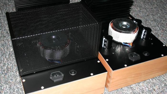
8 Building and Adjustment If you want to build a pair of amps just like the ones in the picture, I have included a supplement to this article which details their construction. The construction guide is available as a PDF download from the publisher s website. The construction method employed is especially good for beginners without machine shops in their basements (The machine shop will come later, friends. You ve been warned. This hobby has that effect). It includes parts lists, sources, some instructions, and pictures. It s the next best thing to a kit, and I think they re sort of retro-cool. The power supplies for this amplifier are independent and floating! Do not attach any of the power supply terminals to ground. That would be bad. Only the mains earth from the IEC connector is attached to the chassis. You need a separate supply for V1 and V2 and since we re building two mono channels, we ll need four supplies. Each pair of supplies can be powered from a single transformer having two independent secondary windings, and many toroidal types are made this way. FIGURE 8 shows a suitable supply for one channel. You can use normal capacitor reservoirs (without the Pi filter) of say ,000 uf which will yield slightly higher, but acceptable, noise figures. If you build the amp according to the construction supplement, the blue LEDs are mounted to the supply PCBs which mount underneath the top plate and give off a nice vacuum-tubey glow from within. I know it s gimmicky, but this is The Amazing FET Circlotron! Figure 8 After you ve built and tested the power supplies, assemble and attach the amp channels. Don t forget V1+ and V2+ are cross-connected. This is very important. Each channel s heat sink will need to dissipate 60W at no more than 25 C above room temperature. The signal ground is important. A faulty connection here might upset the bias and cause things to get hot fast, so check for a good electrical connection. Check for continuity back to the earth tab on the IEC connector. Attach it to the chassis right on top of the mains earth lug. If your chassis is anodized or painted, scrape or sand this area to bare metal. Now it s time to fire them up. Turn P1 and P2 to their minimum positions (fully CCW if you re using the PCBs from the construction guide). Be absolutely sure they are at their minimum settings or you run the risk of destroying the output transistors, which will bring the fun to a screeching halt. 8
9 Ideally, you should have three multitesters for this procedure (the twenty-dollar kind should work fine. Don t go crazy.) Use one each to measure current through the output stage, and one to measure the DC offset at the output. Install a 2-3 Amp slow blow fuse, stand back, and bring the amp up slowly with a variable AC transformer, if you have one. I wear a full face shield and keep a fire extinguisher handy for this. Seriously, in this hobby, things can go pop, melt, and even catch fire, and it often happens at this stage of the game. If you re not familiar with electrical safety in general, do get familiar. There are articles, videos, and classes available online, through your local community college, or possibly your power company. Slowly adjust P1 and P2 upward and observe the voltage across R15 and R16. It is easiest to adjust them alternately in small increments of 1/10th of a turn to keep them in balance. You ll want to measure about 560 mv across each source resistor which corresponds to 1.2A bias. As you approach the target voltages, watch the DC offset meter and adjust the balance for low DC. I found it pretty easy to achieve < 10 mv offset. When the currents are equal, the offset should be near zero, but the lowest offset might be achieved with slightly imbalanced currents. For now, focus mainly on getting the offset low and definitely less than 50 mv. You ll need to readjust the bias after a few hours when the heat sink is fully warmed-up, and repeated adjustments may be needed to get everything just right. It s helpful to put your chassis cover on between adjustments to keep the JFETs close to their normal operating temperatures. When that s done, you re ready to try it out. What Could Go Wrong? I must warn you that there are some things that can go wrong. Firstly, this amp has bridge connected outputs, and if one side of the bridge fails your speaker will see some DC; maybe too much. This would most likely result from losing one of your power rails. This is common to many bridged amps, and some have special protection, and some don t. I just check my power connections really well when I m building and then I don t worry about it. Also, this amp can deliver a hefty amount of current. It doesn t include any sort of current limiting, so if you decide to short the output terminals you might smell some smoke. This means you must take care in making your speaker connections, and always connect your cables and interconnects with the power switched off. 9
10 % THD+N % THD+N Measurements Figure 9 shows the distortion vs. power for an 8 Ohm load. We re around.005% at one Watt and.2% at twenty Watts. FET CIRCLOTRON THD+N VS. 8 OHMS WATTS Figure 9 Figure 10 shows the distortion vs. power for a 4 Ohm load, and here we re around.01% at one Watt and 1% at forty Watts. FET CIRCLOTRON THD+N VS. 4 OHMS WATTS Figure 10 10
11 db % THD+N Figure 11 shows the distortion vs. frequency at one Watt into 8 Ohms. Here we see a fairly flat characteristic out to 1 khz where the distortion begins to rise with frequency. FET CIRCLOTRON THD+N VS. 8 1W HZ Figure 11 Figure 12 shows the FFT at one Watt. The dominant 3 rd harmonic can be seen here FET CIRCLOTRON 1 WATT HZ Figure 12 11
12 dbr Figure 11 is our frequency response, down 1.5 db at 200 khz. FET CIRCLOTRON FREQ RESPONSE HZ Figure 13 Lastly, figure 14 shows our 20 khz square wave response. Figure 14 Tweaking Our amp s measured performance is pretty good, and this is with more or less randomly selected parts. This circuit, as you might expect, will benefit from good symmetry, and a little effort matching parts will pay off. So, what parts should we match? Well, everything if you can. Match your 12
13 JFETs for Idss and your MOSFETS for Vgs. If you re lucky enough to score some dualmonolithic 2SJ109BL JFETs, that d be the cat s pajamas. It s a good idea to have Q1 and Q2 in thermal contact, and you can accomplish this by pressing them together or gluing a small heat sink across their tops. If you decide to match your resistors, some of the values are low and you might need to use a 4- wire measuring technique to get good matches. In the prototypes, I did try to match-up R13 and R14 since they re 5% parts. Other than that, things just got plugged in as they came out of their packages. For R13 and R14, you could substitute the nice TO-220 Caddock power resistors which are noninductive and have a 1% tolerance. I also tried installing a 5K pot across R13 and R14 with the wiper to ground. With this setup, I could dial-in the circuit balance and adjust it for the lowest distortion, but I really didn t need it with the Caddocks. If you like tweaking, go for it. Otherwise, just build it and don t worry so much. Conclusion These amps measure pretty well, and are fairly easy to build and adjust. Once you ve gathered all the parts you can build them in a weekend or two. I m driving mine with a Pass X2 preamp and I ve also tried them driven directly from the balanced outputs of a Benchmark DAC-1. Both worked great, and just about any DIY or commercial balanced preamp (tube or transistor) should work just fine. Now, you re probably wondering how they sound. We ll, first I have to tell you that nothing sounds as good as something you ve built yourself, and I m no Dick Oshler when it comes to describing the sound of components. Having said that, I ll tell you that they sound great, exhibiting many of the qualities audiophiles crave. Build a pair for yourself. I don t think you ll be disappointed. You may even think they re Amazing. I have a blog at where I ll try to post some of the trivial bits that didn t fit in this article (sort of like the out-take reel). You can contact me there, and I d really enjoy seeing pictures of your completed amps. My Quest for Fun Writing this article has been a personal quest for me. I got hooked on the audio hobby while I was serving in the U.S. Army a long time ago. When I joined, I wanted to be an electronics technician, but color-blindness made that impossible. The Army has funny rules. So, I pursued electronics as a hobby. The first (complete) thing I built was a Pass A40, and I ve been building stuff ever since. If you re just getting started in this hobby, you should know that building audio gear usually leads to tweaking, and tweaking may eventually lead to designing. This is my attempt to do just that. I am truly an amateur in the sense that I have a pretty normal day job, but more in the sense that my electronics education is limited to Ohm s Law, what I ve learned by experimenting, and most importantly what I ve learned from the dozens of articles by Nelson Pass. I know I ve dropped his name several times in my article, and the truth is - I just can t thank the guy enough for making this hobby fun. Now go build something! 13


14 14
Burning Amp 2. by Nelson Pass. Introduction. Concept
 Burning Amp 2 by Nelson Pass Introduction In Burning Amp 1 we examined an amplifier circuit designed to complement the hardware we gave away to some attendees at last October's Burning Amp Festival in
To make this design more accessible, is offering a limited number of kits for this design including VFETs, pc boards, and hardware.
 The DIY Sony VFET by Nelson Pass This is an addendum to the Sony SIT AMP part 2 article is the second of a series presenting Do-It-Yourself audio power amplifiers using Static Induction Transistors (SITs),
Burning Amplifier #1 By Nelson Pass April 21, 2009 Rev 1.0. Nelson Pass
 Burning Amplifier #1 By Nelson Pass April 21, 2009 Rev 1.0 Introduction The Burning Amp Festival happens every October in San Francisco. Do-it-yourself audio enthusiasts from all over gather to listen
Now For Something Completely Different: the F7 Power Amplifier. Short Story Long:
 Now For Something Completely Different: the F7 Power Amplifier Short Story Long: Conceived in 2007, the F5 was a push-pull Class A amplifier employing eight semiconductors and 23 resistors to achieve 25
The Aleph 2 is a monoblock 100 watt audio power amplifier which operates in single-ended class A mode.
 Pass Laboratories Aleph 2 Service Manual Rev 0 2/1/96 Aleph 2 Service Manual. The Aleph 2 is a monoblock 100 watt audio power amplifier which operates in single-ended class A mode. The Aleph 2 has only
Burning Amplifier #1. By Nelson Pass 1/22/09. Introduction. Hardware. Concept
 Burning Amplifier #1 By Nelson Pass 1/22/09 Introduction The Burning Amp Festival is an event every October in San Francisco. Do-it-yourself audio enthusiasts from all over gather to show off their projects,
The Aleph 5 is a stereo 60 watt audio power amplifier which operates in single-ended class A mode.
 Pass Laboratories Aleph 5 Service Manual Rev 0 9/20/96 Aleph 5 Service Manual. The Aleph 5 is a stereo 60 watt audio power amplifier which operates in single-ended class A mode. The Aleph 5 has only two
Figure 2 shows the actual schematic for the power supply and one channel.
 Pass Laboratories Aleph 3 Service Manual rev 0 2/1/96 Aleph 3 Service Manual. The Aleph 3 is a stereo 30 watt per channel audio power amplifier which operates in single-ended class A mode. The Aleph 3
AMP CAMP AMP #1. Introduction. Requirements and Constraints. by Nelson Pass
 AMP CAMP AMP #1 by Nelson Pass Introduction Do-It-Yourself audio is a great activity. Many major audio components are easily constructed and made to perform as well or better than what we see in the stores
22A3 Monaural Amplifier Owner s Manual
 22A3 Monaural Amplifier Owner s Manual www.bandwidthaudio.com sales@bandwidthaudio.com WARNING Never power on the amplifier without connecting a proper load Failure to do so will result in permanent damage
The B7 Discrete Operational Amplifier Author: Tamas G. Kohalmi 7/5/2004
 The B7 Discrete Operational Amplifier Author: Tamas G. Kohalmi 7/5/2004 Table of Contents Part 1... pages 2-4 Part 2 pages 5-7 Part 1. This document describes a simple discrete operational amplifier that
The Pearl II Phono Stage. By Wayne Colburn. Introduction
 The Pearl II Phono Stage By Wayne Colburn Introduction Here is the long awaited sequel to the Pearl phono stage, named after my maternal Grandmother who was good with a sling shot, played piano and organ
So far, First Watt has made a few different amplifiers: Very different amplifiers.
 First Watt model F5 Operation and Service Manual So far, First Watt has made a few different amplifiers: Very different amplifiers. Quite a few people have asked me for a regular sort of amplifier, you
Amplifier Classes. nothing! Let us compare this to if the amplifier ONLY had to drive a 4 ohm load the dissipation
 Amplifier Classes Audio amplifiers have been put into different classes The class is dictated by the way the output stages operate. For audio we have five basic classes but one of them pertains to how
3 Circuit Theory. 3.2 Balanced Gain Stage (BGS) Input to the amplifier is balanced. The shield is isolated
 Input to the amplifier is balanced. The shield is isolated") Rev. D CE Series Power Amplifier Service Manual 3 Circuit Theory 3.0 Overview This section of the manual explains the general operation of the CE power amplifier. Topics covered include Front End Operation,
Rev. D CE Series Power Amplifier Service Manual 3 Circuit Theory 3.0 Overview This section of the manual explains the general operation of the CE power amplifier. Topics covered include Front End Operation,
Analyzing the Dynaco Stereo 120 Power Amplifier
 Analyzing the Dynaco Stereo 120 Power Amplifier The Stereo 120 Power Amplifier came out around 1966. It was the first powerful (60 watts per channel) solid state amplifier in wide production. Each channel
First Watt SIT-3 Power Amplifier
 First Watt SIT-3 Power Amplifier OWNERS MANUAL Introduction The SIT-3 is the very latest example of single-ended / single-stage Class A amplifiers using the SIT (aka VFET) power transistor exclusive to
GOLDMUND MIMESIS SRM2.3 MONO AMPLIFIER
 GOLDMUND MIMESIS SRM2.3 MONO AMPLIFIER 1 GOLDMUND MIMESIS SRM2.3 MONO AMPLIFIER USER MANUAL ATTENTION : No connection or manipulation must be done before reading those instructions. Damage to the amplifier
60-100W Hi-Fi Power Amplifier. Rod Elliott (ESP) PCBs are available for this project. Click the image for details.
 PCBs are available for this project. Click the image for details.") Page 1 of 6 Elliott Sound Products Project 3A Introduction 60-100W Hi-Fi Power Amplifier Rod Elliott (ESP) PCBs are available for this project. Click the image for details. Update - 24 Jul 2003. OnSemi
Page 1 of 6 Elliott Sound Products Project 3A Introduction 60-100W Hi-Fi Power Amplifier Rod Elliott (ESP) PCBs are available for this project. Click the image for details. Update - 24 Jul 2003. OnSemi
DISCRETE DIFFERENTIAL AMPLIFIER
 DISCRETE DIFFERENTIAL AMPLIFIER This differential amplifier was specially designed for use in my VK-1 audio oscillator and VK-2 distortion meter where the requirements of ultra-low distortion and ultra-low
Bel Canto Design evo Digital Power Processing Amplifier
 Bel Canto Design evo Digital Power Processing Amplifier Introduction Analog audio power amplifiers rely on balancing the inherent linearity of a device or circuit architecture with factors related to efficiency,
FIRST WATT B4 USER MANUAL
 FIRST WATT B4 USER MANUAL 6/23/2012 Nelson Pass Introduction The B4 is a stereo active crossover filter system designed for high performance and high flexibility. It is intended for those who feel the
Hello, and welcome to the TI Precision Labs video series discussing comparator applications. The comparator s job is to compare two analog input
 Hello, and welcome to the TI Precision Labs video series discussing comparator applications. The comparator s job is to compare two analog input signals and produce a digital or logic level output based
// Parts of a Multimeter
 Using a Multimeter // Parts of a Multimeter Often you will have to use a multimeter for troubleshooting a circuit, testing components, materials or the occasional worksheet. This section will cover how
Copyright 1999 Wheatfield Audio LLC. All rights reserved. Printed in USA 11/99
 HA-2 Headphone Amplifier User s Manual Contents Safety... 3 Unpacking, Setup, and Connection... 4 Unpacking the amplifier... 4 Installing the tubes... 4 Connecting the amplifier... 4 Listening with the
Part 1: Common Source Mode, Transformer Coupled
 Sony VFETs in Push-Pull Class A Part 1: Common Source Mode, Transformer Coupled By Nelson Pass Introduction This article is the first of a series presenting fairly simple Do-It-Yourself audio power amplifiers
ZOTL40 Mk.II POWER AMPLIFIER USER GUIDE. Linear Tube Audio Takoma Park, MD, USA
 ZOTL40 Mk.II POWER AMPLIFIER USER GUIDE Linear Tube Audio Takoma Park, MD, USA WARNING: For safety, the cover of this amplifier should be secured at all times. DC voltages as high as 1000V and peak AC
EE320L Electronics I. Laboratory. Laboratory Exercise #4. Diode Rectifiers and Power Supply Circuits. Angsuman Roy
 EE320L Electronics I Laboratory Laboratory Exercise #4 Diode Rectifiers and Power Supply Circuits By Angsuman Roy Department of Electrical and Computer Engineering University of Nevada, Las Vegas Objective:
Mini Block Ultra Linear Class A Push-Pull Valve Power Amplifier
 Mini Block Ultra Linear Class A Push-Pull Valve Power Amplifier Precaution: This project uses potentially lethal voltages and should not be undertaken by anyone who is not familiar with working with such
Emotiva BasX A300 Stereo Power Amplifier
 Emotiva BasX A300 Stereo Power Amplifier The BasX A-300 is a two channel power amplifier that offers true audiophile sound quality at an affordable price. The BasX A-300 includes a carefully chosen set
JCM W GUITAR AMPLIFIER. User s Manual
 JCM 800 2204 50W GUITAR AMPLIFIER User s Manual 1 Thank you for the purchase of your Ceriatone guitar amplifier! Here, we hope to explain how best to use your new amp. Table of Contents 1) About the 2204..
INPUT: 110/220VAC. Parallel Input Series Input Parallel Output Series Output (W/CT)
") Linear power supply design: To make a simple linear power supply, use a transformer to step down the 120VAC to a lower voltage. Next, send the low voltage AC through a rectifier to make it DC and use a
Linear power supply design: To make a simple linear power supply, use a transformer to step down the 120VAC to a lower voltage. Next, send the low voltage AC through a rectifier to make it DC and use a
Construction notes for the symmetrical 400 watt amplifier
 Construction notes for the symmetrical 400 watt amplifier Introduction The symmetrical amplifier is an update of one of my designs, which appeared in the Australian electronics magazine Silicon Chip in
T-reg revised MOSFET-based high-voltage regulators for tube amps.
 T-reg revised MOSFET-based high-voltage regulators for tube amps. Jan Didden In 2009 I designed a high-voltage regulator for tube equipment [1, 2]. Originally based on a series tube, I also gave circuit
Minimalist Discrete Hi-Fi Preamp
 Minimalist Discrete Hi-Fi Preamp Rod Elliott (ESP) Introduction A preamp designed for the minimalist, and having no frills at all is the design goal for this project. It is designed as a preamp for the
Owner s Manual B 300 B 600 B 900 B 1200 B 1500 B 902 B 1202 B 1802 B300 B1802
 Owner s Manual B 300 B 600 B 900 B 1200 B 1500 B300 B 902 B 1202 B 1802 B1802 WARNING B 300 / B 600 / B 900 / B 1200 / B 1500 / B 902 / B 1202 / B 1802 Table of Contents Table of Contents Introduction
LSJ689. Linear Systems. Application Note. By Bob Cordell. Three Decades of Quality Through Innovation
 Three Decades of Quality Through Innovation P-Channel Dual JFETs Make High-Performance Complementary Input Stages Possible Linear Systems Lower Current Noise Lower Bias Current Required LSJ689 Application
Those of you who have been following this series of articles
 Making A Software Defined Radio for the QRP Enthusiast: Part IV Ward Harriman AE6TY Those of you who have been following this series of articles know that the description of the SDR portion of my project
For the filter shown (suitable for bandpass audio use) with bandwidth B and center frequency f, and gain A:
 with bandwidth B and center frequency f, and gain A:") Basic Op Amps The operational amplifier (Op Amp) is useful for a wide variety of applications. In the previous part of this article basic theory and a few elementary circuits were discussed. In order to
Basic Op Amps The operational amplifier (Op Amp) is useful for a wide variety of applications. In the previous part of this article basic theory and a few elementary circuits were discussed. In order to
G6ALU 20W FET PA Construction Information
 G6ALU 20W FET PA Construction Information The requirement This amplifier was designed specifically to complement the Pic-A-Star transceiver developed by Peter Rhodes G3XJP. From the band pass filter an
Using LME49810 to Build a High-Performance Power Amplifier Part I
 Using LME49810 to Build a High-Performance Power Amplifier Part I Panson Poon Introduction Although switching or Class-D amplifiers are gaining acceptance to audiophile community, linear amplification
Apples vs Apples: Introducing the Common Amplifier Format (CAF) Oct. 07, 2013, by Pat Brown
 Oct. 07, 2013, by Pat Brown") Apples vs Apples: Introducing the Common Amplifier Format (CAF) Oct. 07, 2013, by Pat Brown Last year I was contracted to perform a barrage of measurements to be used to help a theme park select between
Apples vs Apples: Introducing the Common Amplifier Format (CAF) Oct. 07, 2013, by Pat Brown Last year I was contracted to perform a barrage of measurements to be used to help a theme park select between
2 Thermistor + Op-Amp + Relay = Sensor + Actuator
 Physics 221 - Electronics Temple University, Fall 2005-6 C. J. Martoff, Instructor On/Off Temperature Control; Controlling Wall Current with an Op-Amp 1 Objectives Introduce the method of closed loop control
Josephson Engineering, Inc. 329A Ingalls Street Santa Cruz, California Josephson Engineering Rev B
 C725 Users Guide Josephson Engineering, Inc. 329A Ingalls Street Santa Cruz, California +1 831 420 0888 www.josephson.com 2017 Josephson Engineering Rev B C725 Users Guide Josephson C725 microphones are
MZ2 HEADPHONE AMPLIFIER, PREAMP, & STEREO AMPLIFIER USER GUIDE
 MZ2 HEADPHONE AMPLIFIER, PREAMP, & STEREO AMPLIFIER USER GUIDE Linear Tube Audio Takoma Park, MD, USA WARNING: For safety, the cover of this amplifier should be secured at all times. DC voltages as high
An Electronic Variable Load by Dave Chute, KG4BZW
 EDITOR: GEOFF HAINES, N1GY Published Quarterly N1GY@ARRL.NET Summer Edition FROM THE EDITOR: Once again I am happy to report that we have several great articles in the Summer Edition of The WCF Experimenter.
2-Way Active Crossover Model XOVER-2. Xkitz.com. User s Manual. Features. Rev 5.0
 2-Way Active Crossover Model XOVER-2 User s Manual Rev 5.0 Xkitz.com Features 2-way Active Crossover for driving separate woofer and tweeter amplifiers Linkwitz-Riley crossover, 4 th order, 24dB/Octave
JCM W GUITAR AMPLIFIER. User s Manual
 JCM 800 2203 100W GUITAR AMPLIFIER User s Manual 1 Thank you for the purchase of your Ceriatone guitar amplifier! Here, we hope to explain how best to use your new amp. Table of Contents 1) About the 2203..
BENCHMARK MEDIA SYSTEMS, INC.
 BENCHMARK MEDIA SYSTEMS, INC. PPM-1 Meter Card Instruction Manual 1.0 The PPM... 1 1.1 The PPM-1... 1 2.1 Measurement Conventions... 1 2.2 System References... 2 3.0 Connections to the PPM-1 Card... 2
3-Way Active Crossover Model XOVER-3. Xkitz.com. User s Manual. Features. Rev 2.1
 3-Way Active Crossover Model XOVER-3 User s Manual Rev 2.1 Xkitz.com Features 3-way Active Crossover for driving separate subwoofer, midrange and tweeter amplifiers Linkwitz-Riley crossover, 4 th order,
Integrated Circuit: Classification:
 Integrated Circuit: It is a miniature, low cost electronic circuit consisting of active and passive components that are irreparably joined together on a single crystal chip of silicon. Classification:
QUICKSILVER MX-190 OPERATING INSTRUCTIONS ,,-
 QUICKSILVER MX-190 OPERATING INSTRUCTIONS -------..,,- INPUT CONNECTIONS To maintain a short and concise signal path, the input connectors are mounted directly on the plug-in front-end circuit boards.
Project 1 Final System Design and Performance Report. Class D Amplifier
 Taylor Murphy & Remo Panella EE 333 12/12/18 Project 1 Final System Design and Performance Report Class D Amplifier Intro For this project, we designed a class D amplifier circuit. Class D amplifiers work
Balanced Zen Line Stage. Introduction
 Balanced Zen Line Stage Introduction The popularity of the Zen projects points out the interest in very simple linear circuits. They are intended to fuel that interest. The Zen, Bride of Zen, and Son of
University of Utah Electrical Engineering Department ECE 2100 Experiment No. 2 Linear Operational Amplifier Circuits II
 University of Utah Electrical Engineering Department ECE 2100 Experiment No. 2 Linear Operational Amplifier Circuits II Minimum required points = 51 Grade base, 100% = 85 points Recommend parts should
Low Cost, General Purpose High Speed JFET Amplifier AD825
 a FEATURES High Speed 41 MHz, 3 db Bandwidth 125 V/ s Slew Rate 8 ns Settling Time Input Bias Current of 2 pa and Noise Current of 1 fa/ Hz Input Voltage Noise of 12 nv/ Hz Fully Specified Power Supplies:
MC2301. Features and Benefits. Promotional Highlights TUBE POWER AMPLIFIER MCINTOSH LABORATORY INC., 2 CHAMBERS STREET, BINGHAMTON, NEW YORK 13903
 MC2301 Product Preview Page 1 McIntosh Laboratory, Inc., Binghamton, NY 13903 Design Engineering Department PRODUCT PREVIEW MC2301 TUBE POWER AMPLIFIER Project 1336 Promotional Highlights 300 Watts Mono
Moving Coil Cartridge Head Amps
 Page 1 of 7 W. Marshall Leach, Jr. Professor of Electrical and Computer Engineering Georgia Institute of Technology Atlanta, Georgia 30332-0250 Copyright 1999 Prologue For all practical purposes, the disk
Basic Electronics Course Part 2
 Basic Electronics Course Part 2 Simple Projects using basic components Including Transistors & Pots Following are instructions to complete several electronic exercises Image 7. Components used in Part
ECE4902 C Lab 5 MOSFET Common Source Amplifier with Active Load Bandwidth of MOSFET Common Source Amplifier: Resistive Load / Active Load
 ECE4902 C2012 - Lab 5 MOSFET Common Source Amplifier with Active Load Bandwidth of MOSFET Common Source Amplifier: Resistive Load / Active Load PURPOSE: The primary purpose of this lab is to measure the
Chapter 9: Operational Amplifiers
 Chapter 9: Operational Amplifiers The Operational Amplifier (or op-amp) is the ideal, simple amplifier. It is an integrated circuit (IC). An IC contains many discrete components (resistors, capacitors,
Electronics 1. Voltage/Current Resistors Capacitors Inductors Transistors
 Electronics 1 Voltage/Current Resistors Capacitors Inductors Transistors Voltage and Current Simple circuit a battery pushes some electrons around the circuit how many per second? Water The easiest way
Class D audio-power amplifiers: Interactive simulations assess device and filter performance
 designfeature By Duncan McDonald, Transim Technology Corp CLASS D AMPLIFIERS ARE MUCH MORE EFFICIENT THAN OTHER CLASSICAL AMPLIFIERS, BUT THEIR HIGH EFFICIENCY COMES AT THE EXPENSE OF INCREASED NOISE AND
Kaskode One Phono Preamplifier Owner s Manual
 Kaskode One Phono Preamplifier Owner s Manual www.bandwidthaudio.com sales@bandwidthaudio.com WARNING Configuration of the Kaskode One will require removing the cover of the unit. Before removing the cover
Physics 364, Fall 2012, reading due your answers to by 11pm on Thursday
 Physics 364, Fall 2012, reading due 2012-10-25. Email your answers to ashmansk@hep.upenn.edu by 11pm on Thursday Course materials and schedule are at http://positron.hep.upenn.edu/p364 Assignment: (a)
Marchand Electronics Inc.
 Marchand Electronics Inc. Rochester, NY. TEL:(585) 423 0462 www.marchandelec.com Electronic Crossover XM1 XM1 ELECTRONIC CROSSOVER NETWORK In many high performance loudspeaker systems the individual loudspeaker
Audio Amplifier. November 27, 2017
 Audio Amplifier November 27, 2017 1 Pre-lab No pre-lab calculations. 2 Introduction In this lab, you will build an audio power amplifier capable of driving a 8 Ω speaker the way it was meant to be driven...
audionet 4 Channel Amplifier Owner's Manual
 audionet amp Iv 4 Channel Amplifier Owner's Manual Congratulations! For those in need of even more amplification we have engineered the AMP IV. The AMP IV is our power amplifier for multichannel applications
IPR LA-3 KIT last update 15 march 06
 IPR LA-3 KIT last update 15 march 06 PART-2: Audio Circuitry CIRCUIT BOARD LAYOUT: Power and Ground Distribution Now that your power supply is functional, it s time to think about how that power will be
So you just want to light up an LED. What resistor should you use?
 Resistors for LEDs Basics: Picking Resistors for LEDs evilmadscientist.com/2012/resistors-for-leds/ Lenore EdmanAugust 29, 2012 So you just want to light up an LED. What resistor should you use? Maybe
Physics 120 Lab 6 (2018) - Field Effect Transistors: Ohmic Region
 - Field Effect Transistors: Ohmic Region") Physics 120 Lab 6 (2018) - Field Effect Transistors: Ohmic Region The field effect transistor (FET) is a three-terminal device can be used in two extreme ways as an active element in a circuit. One is
Physics 120 Lab 6 (2018) - Field Effect Transistors: Ohmic Region The field effect transistor (FET) is a three-terminal device can be used in two extreme ways as an active element in a circuit. One is
TA4252 Owner s Manual
 TA4252 Owner s Manual Introduction Thank you for choosing MTX to help reach the ultimate goal with your vehicle. Adding MTX amplifiers and matching MTX speakers and subwoofers with StreetWires connections
30 Watt Audio Power Amplifier
 30 Watt Audio Power Amplifier Including Preamp, Tone Controls, Reg dc Power Supply, 18 Watt into 8 Ohm - 30W into 4 Ohm loads Amplifier Section Circuit diagram: Audio Power Amplifier Circuit Diagram This
CEM3378/3379 Voltage Controlled Signal Processors
 CEM3378/3379 Voltage Controlled Signal Processors The CEM3378 and CEM3379 contain general purpose audio signal processing blocks which are completely separate from each other. These devices are useful
The Zen Variations - Part 2
 The Zen Variations - Part 2 The Penultimate Zen s Current Source by Nelson Pass, (c) 2002 Pass Laboratories Intro Welcome back to the Zen Amp Variations. This is part 2 of many parts in which we explore
The ROSE 80 CW Transceiver (Part 1 of 3)
") Build a 5 watt, 80 meter QRP CW Transceiver!!! Page 1 of 10 The ROSE 80 CW Transceiver (Part 1 of 3) Build a 5 watt, 80 meter QRP CW Transceiver!!! (Designed by N1HFX) A great deal of interest has been
Build a 5 watt, 80 meter QRP CW Transceiver!!! Page 1 of 10 The ROSE 80 CW Transceiver (Part 1 of 3) Build a 5 watt, 80 meter QRP CW Transceiver!!! (Designed by N1HFX) A great deal of interest has been
3050 Stereo Power Amplifier
 3050 Stereo Power Amplifier Owners Manual 10/26/2016 Boulder Amplifiers, Inc. 255 Taylor Ave. Louisville, CO 80027 (303) 449-8220 www.boulderamp.com Fault Conditions Boulderlink Appendix Remote Control
1 FUNCTIONAL DESCRIPTION WAY SPLITTER/INPUT BOARD FET RF AMPLIFIERS WAY POWER COMBINER VSWR CONTROL BOARD...
 CONTENTS 1 FUNCTIONAL DESCRIPTION...1 2 4-WAY SPLITTER/INPUT BOARD...2 3 FET RF AMPLIFIERS...3 4 4-WAY POWER COMBINER...4 5 VSWR CONTROL BOARD...5 6 ADJUSTMENT OF BIAS VOLTAGE TO ESTABLISH PROPER QUIESCENT
Lab assignment: Strain gauge
 Lab assignment: Strain gauge In this lab, you will make measurements of mechanical strain in small aluminum beams as you bend them. We will also work with our first integrated circuit component on the
Designing Microphone Preamplifiers. Steve Green 24th AES UK Conference June 2011
 Designing Microphone Preamplifiers Steve Green 24th AES UK Conference June 2011 This presentation is an abbreviated version of a tutorial given at the 2010 AES Conference in San Francisco. The complete
PREVIEW COPY. Amplifiers. Table of Contents. Introduction to Amplifiers...3. Single-Stage Amplifiers...19
 Amplifiers Table of Contents Lesson One Lesson Two Lesson Three Introduction to Amplifiers...3 Single-Stage Amplifiers...19 Amplifier Performance and Multistage Amplifiers...35 Lesson Four Op Amps...51
EE320L Electronics I. Laboratory. Laboratory Exercise #2. Basic Op-Amp Circuits. Angsuman Roy. Department of Electrical and Computer Engineering
 EE320L Electronics I Laboratory Laboratory Exercise #2 Basic Op-Amp Circuits By Angsuman Roy Department of Electrical and Computer Engineering University of Nevada, Las Vegas Objective: The purpose of
d. Can you find intrinsic gain more easily by examining the equation for current? Explain.
 EECS140 Final Spring 2017 Name SID 1. [8] In a vacuum tube, the plate (or anode) current is a function of the plate voltage (output) and the grid voltage (input). I P = k(v P + µv G ) 3/2 where µ is a
Brief Installation Procedure: 1. Check the Parts 2. assembly each channel in brief and make sure the assembly is correct. 3. assembly the chassis in
 Brief Installation Procedure: 1. Check the Parts 2. assembly each channel in brief and make sure the assembly is correct. 3. assembly the chassis in brief, and make sure no small parts missed. 4. fixed
University of North Carolina, Charlotte Department of Electrical and Computer Engineering ECGR 3157 EE Design II Fall 2009
 University of North Carolina, Charlotte Department of Electrical and Computer Engineering ECGR 3157 EE Design II Fall 2009 Lab 1 Power Amplifier Circuits Issued August 25, 2009 Due: September 11, 2009
Electrical Engineer. Lab2. Dr. Lars Hansen
 Electrical Engineer Lab2 Dr. Lars Hansen David Sanchez University of Texas at San Antonio May 5 th, 2009 Table of Contents Abstract... 3 1.0 Introduction and Product Description... 3 1.1 Problem Specifications...
USER MANUAL. GOLDMUND SR150 2-CHANNEL Universal Power Amplifier
 USER MANUAL GOLDMUND SR150 2-CHANNEL Universal Power Amplifier Congratulations. Thank you for purchasing the Goldmund SR150 2-CHANNEL Universal Power Amplifier. You have acquired the best multi-usage Power
Diodes. Analog Electronics Lesson 4. Objectives and Overview:
 Analog Electronics Lesson 4 Diodes Objectives and Overview: This lesson will introduce p- and n-type material, how they form a junction that rectifies current, and familiarize you with basic p-n junction
Power Supplies and Circuits. Bill Sheets K2MQJ Rudolf F. Graf KA2CWL
 Power Supplies and Circuits Bill Sheets K2MQJ Rudolf F. Graf KA2CWL The power supply is an often neglected important item for any electronics experimenter. No one seems to get very excited about mundane
Rowan University Freshman Clinic I Lab Project 2 The Operational Amplifier (Op Amp)
") Rowan University Freshman Clinic I Lab Project 2 The Operational Amplifier (Op Amp) Objectives Become familiar with an Operational Amplifier (Op Amp) electronic device and it operation Learn several basic
Rowan University Freshman Clinic I Lab Project 2 The Operational Amplifier (Op Amp) Objectives Become familiar with an Operational Amplifier (Op Amp) electronic device and it operation Learn several basic
User s Manual for Integrator Short Pulse ISP16 10JUN2016
 User s Manual for Integrator Short Pulse ISP16 10JUN2016 Specifications Exceeding any of the Maximum Ratings and/or failing to follow any of the Warnings and/or Operating Instructions may result in damage
Opamp Based Power Amplifier
 Introduction Opamp Based Power Amplifier Rohit Balkishan This is a contributed project from Rohit Balkishan, who has built it, and thought that it would make a nice simple project for others. This is a
Power Amplifiers. Class A Amplifier
 Power Amplifiers The Power amplifiers amplify the power level of the signal. This amplification is done in the last stage in audio applications. The applications related to radio frequencies employ radio
A Simple Capacitance Multiplier Power Supply For Class-A Amplifiers Rod Elliott - ESP (Original Design / Basic Principles)
") 1 / 7 2010.12.18. 7:58 DC Programmable Power Benchtop & Rackmount Power Supplies Sorensen / Power 10 / Argantix www.sorensen.com Elliott Sound Products Project 15 Share Introduction A Simple Capacitance
1 / 7 2010.12.18. 7:58 DC Programmable Power Benchtop & Rackmount Power Supplies Sorensen / Power 10 / Argantix www.sorensen.com Elliott Sound Products Project 15 Share Introduction A Simple Capacitance
USER MANUAL. GOLDMUND TELOS 2500 NextGen Universal Power Amplifier
 USER MANUAL GOLDMUND TELOS 2500 NextGen Universal Power Amplifier Thank you for purchasing the GOLDMUND TELOS 2500 NextGen. You have acquired the best Universal Power Amplifier ever made for professional
As delivered power levels approach 200W, sometimes before then, heatsinking issues become a royal pain. PWM is a way to ease this pain.
 1 As delivered power levels approach 200W, sometimes before then, heatsinking issues become a royal pain. PWM is a way to ease this pain. 2 As power levels increase the task of designing variable drives
EE4902 C Lab 5 MOSFET Common Source Amplifier with Active Load Bandwidth of MOSFET Common Source Amplifier: Resistive Load / Active Load
 EE4902 C200 - Lab 5 MOSFET Common Source Amplifier with Active Load Bandwidth of MOSFET Common Source Amplifier: Resistive Load / Active Load PURPOSE: The primary purpose of this lab is to measure the
El-Cheapo - A Really Simple Power Amplifier
 El-Cheapo - A Really Simple Power Amplifier Rod Elliott - ESP (Semi-Original Design) "Semi-Original Design" - What is that supposed to mean? Well, many years ago, there was an amplifier circuit in a magazine
High Efficiency Power Amplifier Module
 High Efficiency Power Amplifier Module Highlights Flat, fully load-independent frequency response Low output impedance Very low, frequency-independent THD Very low noise Fully passive loop control Consistent
Input Stage Concerns. APPLICATION NOTE 656 Design Trade-Offs for Single-Supply Op Amps
 Maxim/Dallas > App Notes > AMPLIFIER AND COMPARATOR CIRCUITS Keywords: single-supply, op amps, amplifiers, design, trade-offs, operational amplifiers Apr 03, 2000 APPLICATION NOTE 656 Design Trade-Offs