EE320L Electronics I. Laboratory. Laboratory Exercise #2. Basic Op-Amp Circuits. Angsuman Roy. Department of Electrical and Computer Engineering
|
|
|
- Daniel Barker
- 6 years ago
- Views:
Transcription
1 EE320L Electronics I Laboratory Laboratory Exercise #2 Basic Op-Amp Circuits By Angsuman Roy Department of Electrical and Computer Engineering University of Nevada, Las Vegas Objective: The purpose of this lab is to understand the basics of operational amplifiers, their use as inverting and noninverting amplifiers and gain-bandwidth trade-offs. Equipment Used: Power Supply Oscilloscope Function Generator Breadboard Jumper Wires TL082 or LF412 Dual JFET Input Operational Amplifiers 10x Scope Probes Various Resistors and Capacitors
2 Background: Basic Op-Amp Circuits The operational amplifier or op-amp is perhaps the most important electronic component ever invented. With a minimal of understanding of its inner workings, anyone can use an op-amp for common electronic engineering tasks such as amplification and filtering. The name operational amplifier comes from the fact that historically they were used to perform mathematical operations particularly integration and differentiation. Many real world problems modeled by differential equations were solved using op-amps. This role has completely been superseded by digital computers in the modern era. The first op-amps appeared in the late 1940s and were based on vacuum tubes crammed into a brick sized module. With the invention of transistors these modules became smaller bricks. Finally, the invention of the low-cost monolithic (fabricated on a single chip) op-amp resulted in op-amps being incorporated in almost all electronic devices. The availability of low-cost, high performance op-amps allows the design of sophisticated electronic circuits with a minimal of math equations and dispenses with the complicated biasing schemes of discrete transistor circuitry. A modern op-amp has dozens to hundreds of transistors integrated on a single chip. It is not necessary to understand how the internal circuitry works in order to use the op-amp; it can be treated as a black-box device. The symbol for an op-amp is shown in fig. 1. This is the most basic op-amp symbol with five terminals comprised of positive (non-inverting) and negative (inverting) inputs; V+ and V- supply terminals; and one output. All equations that describe the behavior of op-amp circuits rely on certain assumptions about the op-amp. These assumptions about an ideal op-amp are summarized in table 1 and compared to the real op-amp used in this lab, the TL082. A modern op-amp approaches an ideal op-amp when used within its bandwidth and output limitations. For non-critical applications the ideal op-amp assumptions are valid. In the case of the TL082 as long as the device is operated at low frequencies and does not exceed its rated output voltage and current limits the ideal assumptions are valid. Figure 1 Basic Op-Amp Symbol
3 Parameter Ideal Op-Amp TL082 Input Resistance looking Into Infinite 1 Tera-ohm Vin+ and Vin- Terminals Open Loop Gain Infinite 200,000 Bandwidth Infinite 3 MHz Voltage Output Infinite +/- 13.5V Current Output Infinite 20mA Output Resistance Zero 80 ohm (open-loop) Input Offset Voltage Zero 3 mv Input Bias Current Zero 30 pa Table 1 Comparison of Ideal Op-Amp and TL082 The behavior of an op-amp can be described by two rules. These rules are: 1. An op-amp will attempt to make the voltage at both its inputs equal through the use of a feedback path. 2. If rule one cannot be followed, then the output takes the polarity of the input with higher magnitude. The function of most op-amp circuits is based on these two rules. An example of op-amp behavior that can be explained by rule 1 is the case of the simple inverting amplifier. This circuit configuration is shown in fig. 2. With nothing applied to the input, the op-amp s output follows the voltage at the positive input which is grounded. Both inputs and the output are at 0V. Rule #1 is satisfied. If a 1V positive step is applied to Vin, then this equilibrium is disturbed. A current flows through the Rin resistor equal to the zero comes from the fact that the inverting input was at zero volts. This current cannot flow into the inverting input of the op-amp because of the infinite input resistance. When current is injected into a node the voltage at that node rises. Conversely when current is taken out of a node the voltage at that node falls. The voltage at the inverting input begins to rise, which causes the output voltage to drop. This is because of the nature of the inverting input; the output does the opposite of what is applied to the inverting input. As the output voltage drops, a current begins to flow because of the imbalance in voltage between the inverting input and the output. This current flow, being of opposite sign, cancels out the input current. This current cancelation is what maintains the inverting input at zero volts. The current flowing through the feedback resistor causes a voltage drop which is the output voltage. The most important thing to remember is that the currents flowing in Rin and Rf are equal. If Rf is larger than Rin, to maintain an equal current the voltage at Vout must be of larger magnitude than the voltage at Vin. This is what causes this circuit to operate as a voltage amplifier. This explanation may seem more complicated than the traditional explanation seen in textbooks; however it is more intellectually satisfying.
4 Figure 2 Inverting Amplifier with All Inputs and Outputs in Equilibrium Figure 3 Current Flow in Inverting Amplifier
5 The traditional explanation of the inverting amplifier uses only one current as shown in fig. 4. The input current that flows into the input resistor cannot flow into the inverting input. It must flow through the feedback resistor Rf since this is the only path. However since current flows from positive to negative, the voltage at the output must be negative since the voltage at the inverting input is zero. In this case zero is the higher voltage. There is nothing wrong with this explanation, however it isn t clear what exactly the op-amp is doing. It fades into the background when it should be portrayed as the main actor. Figure 4 Traditional Analysis of Inverting Amplifier The analysis of the non-inverting amplifier is considerably simpler. A schematic of the non-inverting amplifier is shown below in fig. 5. If a voltage is applied to the noninverting input then the output voltage will become whatever value is necessary to maintain the inverting input at the same value as the non-inverting input. The two resistors Rf and Rg form a voltage divider between the output of the op-amp and the inverting input. This means that there will always be a fixed relationship between the voltage at the inverting input and the output. This is what causes amplification. The relationship is clearly seen in the given equation for the inverting node voltage in fig. 5. For an example with numbers, assume that a 1V input is applied into the noninverting input and assume that Rf has a value of 10k and Rg has a value of 1k. For 1V to appear at the inverting input, the output needs to be at 11V. This 11V is divided down by the voltage divider to 1V. Finally, from the formula it is clear that omitting Rg completely created an amplifier with a gain of 1. This topology is called a unity gain buffer. The feedback resistor can be removed and the output directly shorted to the inverting terminal but it is good practice to use a small feedback resistor (1-10 ohm) to prevent oscillation.
6 Figure 5 Non-inverting Amplifier One of the most important parameters when selecting an op-amp is the gain-bandwidth product. The gain-bandwidth product, as implied by the name, is simply the product of the maximum open-loop gain at DC with the bandwidth of the amplifier at a gain of one. There is a trade-off between the gain of an op-amp and its bandwidth. This is illustrated in fig. 6 below. The maximum gain of 110dB or 200,000 is only possible for input signals which are at a very low frequency, typically under a few dozen Hz. After this point, the gain falls as frequency increases. The gain-bandwidth product appears as a straight line when plotted on a graph with X and Y logarithmic axes. Fig. 7 shows how to use the gain-bandwidth plot to characterize the bandwidth of an amplifier. The frequency response is constant until the green line hits the orange line, after which there is steady 10dB attenuation per decade. Since most manufacturers don t provide this graph on their datasheets it is important to learn how to calculate the bandwidth for an amplifier with a certain gain. For example let s say that a gain of 100 with a bandwidth of 100 KHz is desired. The product of these two numbers is 10 million. This requires an op-amp with a specified GBW product of 10 million or a unity-gain bandwidth of 10 MHz. For most general purpose op-amps it is appropriate to use the unity-gain bandwidth specified on the datasheet as the GBW product.
7 Figure 6 Gain Bandwidth Product for TL082 Op-Amp Figure 7 Bandwidth for Different Amplifier Gains

8 Prelab: Analysis 1: Transient Simulation of Inverting Amplifier Simulate an inverting amplifier with a gain of -10 as shown in fig. 8 below. The op-amp is the UniversalOpamp2 component found in the Opamps directory of LTSpice. Fig. 9 shows the selection of this component. The parameters of this part need to be edited to accurately match the parameters of the desired op-amp. Right-clicking on the op-amp symbol brings up the attribute editor in fig. 10. Change the default values to the ones seen in fig. 10. These values are taken from the datasheet of the LF412CN op-amp. These values are reproduced from the datasheet in fig. 11. Next, edit the voltage source s parameters at the input of the op-amp by right-clicking on it. Match the values to be the same as fig. 12. The reason for using a series resistance of 50 ohm is to accurately model the function generator in the lab which has a 50 ohm output impedance. For our frequencies it is unlikely that this parameter has much influence but it is good to include it for the sake of completeness. Also the AC value of 1V is not needed for a transient simulation but it will be used in the next simulation. Next, edit the simulation command to run a transient analysis for 10m seconds as shown in fig. 13. The input and output waveforms should look like fig. 14. The output is 10 times larger in amplitude and inverted compared to the input. Figure 8 Inverting Amplifier with a Gain of -10
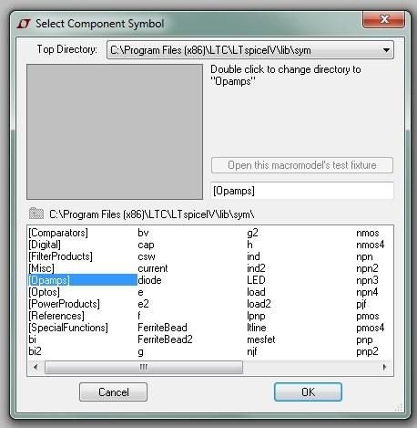
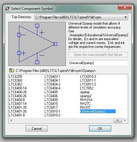
9 Figure 9 UniversalOpamp2

10 Figure 10 Attribute Editor for UniversalOpamp2


11 Figure 11 LF412CN Datasheet Excerpt


12 Figure 12 Voltage Source Parameters Figure 13 Simulation Command
13 Figure 14 Input and Output for an Inverting Amplifier with a Gain of 10 Analysis 2: Gain vs. Bandwidth (inverting) A good way to illustrate the gain-bandwidth trade-off of an op-amp is to run an AC analysis in SPICE for different gains. Create the schematic shown below in fig. 15. A big difference between this schematic and the previous one is the value for R2. The value should be entered as {R} as shown in fig. 16. Entering a letter within curly brackets in SPICE for any parameter tells the simulator that this value can be varied. The reason we are doing this is so we can run the simulation three times for three different values of R2 and graph it all on the same plot. As shown in fig. 15, enter a SPICE directive exactly as shown.step param R list 1k 10k 100k. This line of code tells SPICE to vary the parameter R s value to 1k, 10k and 100k. The list command steps through the discrete values entered. There are other commands that can linearly vary a variable s value too. Next, edit the simulation command to an AC analysis with the values shown in fig. 17. Probing the output should result in the plot displayed in fig. 18.


14 Figure 15 AC Analysis for Inverting Amplifier Figure 16 Value for R2 Figure 17 AC Analysis

15 Figure 18 Frequency Response for Gains of -100, -10, -1 Analysis 3: Gain vs. Bandwidth (noninverting) Repeat exercise 2 but using the circuit shown in fig. 19. Be sure to note the change in values for the R parameter. This simulation only shows the frequency response for gains of 10 and 100. This is because in order to show the frequency response for a gain of 1, we need to delete the resistor R1. This will be done in the next exercise. The result of this simulation is shown in fig. 20. Figure 19 AC Analysis for Non-Inverting Amplifier
16 Figure 20 Frequency Response for Gains of 100 and 10 Analysis 4: Unity Gain Bandwidth Finally, run an AC analysis for a non-inverting amplifier with a gain of 1 as seen in the schematic below in fig. 21. Notice that R1 has been completely removed. R2 isn t necessary and the inverting input can be directly shorted to the output but it is good practice to use a small resistor for R2 for stability. The frequency response is shown in fig. 22.

17 Figure 21 Non-Inverting Amplifier with a Gain of 1 Figure 22 Frequency Response for a gain of 1
18 Prelab Deliverables: 1. Screen captures of schematics and outputs for each prelab exercise. 2. You must also include an Altium schematic, Altium netlist, and PCB layout for the circuits in prelabs 1 through 5. Each PCB layout must include footprints for all components used and can be auto routed or manually routed. You may use either thruhole footprints or surface mount footprints for each component. (For the voltage and current sources just put a two pin header and label them VCC and GND.) Also include a grounding plane and make sure your traces are wide enough for the increase in current. To determine the trace width use a PCB trace calculator. If you are unsure how to use Altium please click on the Lab Equipment, Learning, Tutorials, Manuals, Downloads link on the UNLV EE Labs homepage and read the Altium tutorial or watch the videos.
. Attach 10x probes to both the input and output of the amplifier. Verify that the gain is correct.")
19 Laboratory Experiments: Experiment 1: Inverting Amplifier with Gains of 1, 10 and 100. Construct the circuit shown in fig. 15. Connect a function generator to the input of the circuit. Apply a low frequency, low amplitude signal (such as 100 mv and 1 KHz). Attach 10x probes to both the input and output of the amplifier. Verify that the gain is correct. Next, increase the frequency until the output of the amplifier drops 3dB. (Hint: this occurs at of the original voltage level). The frequency at which this occurs is the bandwidth of the amplifier. Record this value. Repeat this experiment for all gain values. You may have to vary the amplitude of the input signal in order to prevent the op-amp from saturating. For a gain of 100, the function generator may not output the low amplitude needed to prevent saturation. This can be solved by using either a voltage divider or terminating the function generator with a 50 ohm resistor which will halve the voltage output at the input of the op-amp. Experiment 2: Non-inverting Amplifier with Gains of 1, 10 and 100. Construct the circuit shown in figure 19. Repeat everything that was done in experiment 1. For the unity gain buffer construct the circuit shown in fig. 21. An example scope trace showing output (top) and input (bottom) for a non-inverting amplifier with a gain of 10.
20 Postlab Deliverables and Questions: 1. Submit a picture of your breadboard with your circuit on it. 2. Submit a picture of both input and output on the scope for each circuit topology and gain e.g. inverting 1X, inverting 10X, inverting 100X etc. 3. Create a table summarizing bandwidth and gain for each topology. 4. From the table create a rudimentary gain-bandwidth plot. 5. Questions: a. What striking difference in bandwidth do you notice about the inverting and noninverting amplifiers? If you needed to use an op-amp for a high bandwidth application which topology would you likely use? b. Can an op-amp be used as an attenuator? An attenuator has a gain of less than one. Which topology needs to be used? Design an attenuator that will output 1/10 th of the voltage applied to the input. c. Go to an IC manufacturer s website such as Linear Technology, Texas Instruments, Analog Devices or other manufacturer; select an op-amp that appeals to you; and write down the part number, its GBW product and its open-loop gain.
21 Additional Resources 1. Op Amps for Everyone The best reference on how to use Op-Amps with qualitative analysis and quantitative design equations, a must read This website has a clear practical guide to designing with op-amps. 3. Microelectronic Circuits by Sedra/Smith 6 th Edition This is a very large textbook that describes a wide variety of useful circuits.
EE320L Electronics I. Laboratory. Laboratory Exercise #3. Operational Amplifier Application Circuits. Angsuman Roy
 EE320L Electronics I Laboratory Laboratory Exercise #3 Operational Amplifier Application Circuits By Angsuman Roy Department of Electrical and Computer Engineering University of Nevada, Las Vegas Objective:
EE320L Electronics I. Laboratory. Laboratory Exercise #6. Current-Voltage Characteristics of Electronic Devices. Angsuman Roy
 EE320L Electronics I Laboratory Laboratory Exercise #6 Current-Voltage Characteristics of Electronic Devices By Angsuman Roy Department of Electrical and Computer Engineering University of Nevada, Las
EE 3305 Lab I Revised July 18, 2003
 Operational Amplifiers Operational amplifiers are high-gain amplifiers with a similar general description typified by the most famous example, the LM741. The LM741 is used for many amplifier varieties
EE 210 Lab Exercise #5: OP-AMPS I
 EE 210 Lab Exercise #5: OP-AMPS I ITEMS REQUIRED EE210 crate, DMM, EE210 parts kit, T-connector, 50Ω terminator, Breadboard Lab report due at the ASSIGNMENT beginning of the next lab period Data and results
EK307 Active Filters and Steady State Frequency Response
 EK307 Active Filters and Steady State Frequency Response Laboratory Goal: To explore the properties of active signal-processing filters Learning Objectives: Active Filters, Op-Amp Filters, Bode plots Suggested
ECE3204 D2015 Lab 1. See suggested breadboard configuration on following page!
 ECE3204 D2015 Lab 1 The Operational Amplifier: Inverting and Non-inverting Gain Configurations Gain-Bandwidth Product Relationship Frequency Response Limitation Transfer Function Measurement DC Errors
LABORATORY 5 v3 OPERATIONAL AMPLIFIER
 University of California Berkeley Department of Electrical Engineering and Computer Sciences EECS 100, Professor Bernhard Boser LABORATORY 5 v3 OPERATIONAL AMPLIFIER Integrated operational amplifiers opamps
Physics 303 Fall Module 4: The Operational Amplifier
 Module 4: The Operational Amplifier Operational Amplifiers: General Introduction In the laboratory, analog signals (that is to say continuously variable, not discrete signals) often require amplification.
AN-1106 Custom Instrumentation Amplifier Design Author: Craig Cary Date: January 16, 2017
 AN-1106 Custom Instrumentation Author: Craig Cary Date: January 16, 2017 Abstract This application note describes some of the fine points of designing an instrumentation amplifier with op-amps. We will
EE320L Electronics I. Laboratory. Laboratory Exercise #4. Diode Rectifiers and Power Supply Circuits. Angsuman Roy
 EE320L Electronics I Laboratory Laboratory Exercise #4 Diode Rectifiers and Power Supply Circuits By Angsuman Roy Department of Electrical and Computer Engineering University of Nevada, Las Vegas Objective:
UNIVERSITY OF NORTH CAROLINA AT CHARLOTTE Department of Electrical and Computer Engineering
 UNIVERSITY OF NORTH CAROLINA AT CHARLOTTE Department of Electrical and Computer Engineering EXPERIMENT 5 GAIN-BANDWIDTH PRODUCT AND SLEW RATE OBJECTIVES In this experiment the student will explore two
OPERATIONAL AMPLIFIERS (OP-AMPS) II
 II") OPERATIONAL AMPLIFIERS (OP-AMPS) II LAB 5 INTRO: INTRODUCTION TO INVERTING AMPLIFIERS AND OTHER OP-AMP CIRCUITS GOALS In this lab, you will characterize the gain and frequency dependence of inverting op-amp
OPERATIONAL AMPLIFIERS (OP-AMPS) II LAB 5 INTRO: INTRODUCTION TO INVERTING AMPLIFIERS AND OTHER OP-AMP CIRCUITS GOALS In this lab, you will characterize the gain and frequency dependence of inverting op-amp
CHARACTERIZATION OF OP-AMP
 EXPERIMENT 4 CHARACTERIZATION OF OP-AMP OBJECTIVES 1. To sketch and briefly explain an operational amplifier circuit symbol and identify all terminals. 2. To list the amplifier stages in a typical op-amp
Operational Amplifiers
 Operational Amplifiers Reading Horowitz & Hill handout Notes, Chapter 9 Introduction and Objective In this lab we will examine op-amps. We will look at a few of their vast number of uses and also investigate
ECE Lab #4 OpAmp Circuits with Negative Feedback and Positive Feedback
 ECE 214 Lab #4 OpAmp Circuits with Negative Feedback and Positive Feedback 20 February 2018 Introduction: The TL082 Operational Amplifier (OpAmp) and the Texas Instruments Analog System Lab Kit Pro evaluation
LT Spice Getting Started Very Quickly. First Get the Latest Software!
 LT Spice Getting Started Very Quickly First Get the Latest Software! 1. After installing LT Spice, run it and check to make sure you have the latest version with respect to the latest version available
University of Pittsburgh
 University of Pittsburgh Experiment #1 Lab Report Frequency Response of Operational Amplifiers Submission Date: 05/29/2018 Instructors: Dr. Ahmed Dallal Shangqian Gao Submitted By: Nick Haver & Alex Williams
EE431 Lab 1 Operational Amplifiers
 Feb. 10, 2015 Report all measured data and show all calculations Introduction The purpose of this laboratory exercise is for the student to gain experience with measuring and observing the effects of common
DEPARTMENT OF ELECTRICAL ENGINEERING AND COMPUTER SCIENCE MASSACHUSETTS INSTITUTE OF TECHNOLOGY CAMBRIDGE, MASSACHUSETTS 02139
 DEPARTMENT OF ELECTRICAL ENGINEERING AND COMPUTER SCIENCE MASSACHUSETTS INSTITUTE OF TECHNOLOGY CAMBRIDGE, MASSACHUSETTS 019.101 Introductory Analog Electronics Laboratory Laboratory No. READING ASSIGNMENT
Lab 2: Discrete BJT Op-Amps (Part I)
") Lab 2: Discrete BJT Op-Amps (Part I) This is a three-week laboratory. You are required to write only one lab report for all parts of this experiment. 1.0. INTRODUCTION In this lab, we will introduce and
Lab 2: Discrete BJT Op-Amps (Part I) This is a three-week laboratory. You are required to write only one lab report for all parts of this experiment. 1.0. INTRODUCTION In this lab, we will introduce and
Non_Inverting_Voltage_Follower -- Overview
 Non_Inverting_Voltage_Follower -- Overview Non-Inverting, Unity-Gain Amplifier Objectives: After performing this lab exercise, learner will be able to: Understand and comprehend working of opamp Design
Integrators, differentiators, and simple filters
 BEE 233 Laboratory-4 Integrators, differentiators, and simple filters 1. Objectives Analyze and measure characteristics of circuits built with opamps. Design and test circuits with opamps. Plot gain vs.
Assignment 8 Analyzing Operational Amplifiers in MATLAB and PSpice
 ECEL 301 ECE Laboratory I Dr. A. Fontecchio Assignment 8 Analyzing Operational Amplifiers in MATLAB and PSpice Goal Characterize critical parameters of the inverting or non-inverting opampbased amplifiers.
EE 233 Circuit Theory Lab 3: First-Order Filters
 EE 233 Circuit Theory Lab 3: First-Order Filters Table of Contents 1 Introduction... 1 2 Precautions... 1 3 Prelab Exercises... 2 3.1 Inverting Amplifier... 3 3.2 Non-Inverting Amplifier... 4 3.3 Integrating
Analog Electronics. Lecture Pearson Education. Upper Saddle River, NJ, All rights reserved.
 Analog Electronics V Lecture 5 V Operational Amplifers Op-amp is an electronic device that amplify the difference of voltage at its two inputs. V V 8 1 DIP 8 1 DIP 20 SMT 1 8 1 SMT Operational Amplifers
10: AMPLIFIERS. Circuit Connections in the Laboratory. Op-Amp. I. Introduction
 10: AMPLIFIERS Circuit Connections in the Laboratory From now on you will construct electrical circuits and test them. The usual way of constructing circuits would be to solder each electrical connection
PURPOSE: NOTE: Be sure to record ALL results in your laboratory notebook.
 EE4902 Lab 9 CMOS OP-AMP PURPOSE: The purpose of this lab is to measure the closed-loop performance of an op-amp designed from individual MOSFETs. This op-amp, shown in Fig. 9-1, combines all of the major
Experiment #6: Biasing an NPN BJT Introduction to CE, CC, and CB Amplifiers
 SCHOOL OF ENGINEERING AND APPLIED SCIENCE DEPARTMENT OF ELECTRICAL AND COMPUTER ENGINEERING ECE 2115: ENGINEERING ELECTRONICS LABORATORY Experiment #6: Biasing an NPN BJT Introduction to CE, CC, and CB
EE 2274 RC and Op Amp Circuit Completed Prior to Coming to Lab. Prelab Part I: RC Circuit
 EE 2274 RC and Op Amp Circuit Completed Prior to Coming to Lab Prelab Part I: RC Circuit 1. Design a high pass filter (Fig. 1) which has a break point f b = 1 khz at 3dB below the midband level (the -3dB
ECEN Network Analysis Section 3. Laboratory Manual
 ECEN 3714----Network Analysis Section 3 Laboratory Manual LAB 07: Active Low Pass Filter Oklahoma State University School of Electrical and Computer Engineering. Section 3 Laboratory manual - 1 - Spring
Data Conversion and Lab Lab 1 Fall Operational Amplifiers
 Operational Amplifiers Lab Report Objectives Materials See separate report form located on the course webpage. This form should be completed during the performance of this lab. 1) To construct and operate
Lab 1: Non-Ideal Operational Amplifier and Op-Amp Circuits
 Lab 1: Non-Ideal Operational Amplifier and Op-Amp Circuits 1. Learning Outcomes In this lab, the students evaluate characteristics of the non-ideal operational amplifiers. Students use a simulation tool
I1 19u 5V R11 1MEG IDC Q7 Q2N3904 Q2N3904. Figure 3.1 A scaled down 741 op amp used in this lab
 Lab 3: 74 Op amp Purpose: The purpose of this laboratory is to become familiar with a two stage operational amplifier (op amp). Students will analyze the circuit manually and compare the results with SPICE.
EMG Electrodes. Fig. 1. System for measuring an electromyogram.
 1270 LABORATORY PROJECT NO. 1 DESIGN OF A MYOGRAM CIRCUIT 1. INTRODUCTION 1.1. Electromyograms The gross muscle groups (e.g., biceps) in the human body are actually composed of a large number of parallel
EE 221 L CIRCUIT II. by Ming Zhu
 EE 221 L CIRCUIT II LABORATORY 6: OP AMP CIRCUITS by Ming Zhu DEPARTMENT OF ELECTRICAL AND COMPUTER ENGINEERING UNIVERSITY OF NEVADA, LAS VEGAS OBJECTIVE Learn to use Op Amp to implement simple linear
EE 233 Circuit Theory Lab 2: Amplifiers
 EE 233 Circuit Theory Lab 2: Amplifiers Table of Contents 1 Introduction... 1 2 Precautions... 1 3 Prelab Exercises... 2 3.1 LM348N Op-amp Parameters... 2 3.2 Voltage Follower Circuit Analysis... 2 3.2.1
Lab 1: Non-Ideal Operational Amplifier and Op-Amp Circuits
 Lab 1: Non-Ideal Operational Amplifier and Op-Amp Circuits 1. Learning Outcomes In this lab, the students evaluate characteristics of the non-ideal operational amplifiers. Students use a simulation tool
Lab 4: Analysis of the Stereo Amplifier
 ECE 212 Spring 2010 Circuit Analysis II Names: Lab 4: Analysis of the Stereo Amplifier Objectives In this lab exercise you will use the power supply to power the stereo amplifier built in the previous
DEPARTMENT OF ELECTRICAL ENGINEERING AND COMPUTER SCIENCE MASSACHUSETTS INSTITUTE OF TECHNOLOGY CAMBRIDGE, MASSACHUSETTS 02139
 DEPARTMENT OF ELECTRICAL ENGINEERING AND COMPUTER SCIENCE MASSACHUSETTS INSTITUTE OF TECHNOLOGY CAMBRIDGE, MASSACHUSETTS 019 Spring Term 00.101 Introductory Analog Electronics Laboratory Laboratory No.
BME/ISE 3512 Bioelectronics. Laboratory Five - Operational Amplifiers
 BME/ISE 3512 Bioelectronics Laboratory Five - Operational Amplifiers Learning Objectives: Be familiar with the operation of a basic op-amp circuit. Be familiar with the characteristics of both ideal and
Concepts to be Reviewed
 Introductory Medical Device Prototyping Analog Circuits Part 3 Operational Amplifiers, http://saliterman.umn.edu/ Department of Biomedical Engineering, University of Minnesota Concepts to be Reviewed Operational
ECE4902 C Lab 7
 ECE902 C2012 - Lab MOSFET Differential Amplifier Resistive Load Active Load PURPOSE: The primary purpose of this lab is to measure the performance of the differential amplifier. This is an important topology
ECE4902 Lab 5 Simulation. Simulation. Export data for use in other software tools (e.g. MATLAB or excel) to compare measured data with simulation
 to compare measured data with simulation") ECE4902 Lab 5 Simulation Simulation Export data for use in other software tools (e.g. MATLAB or excel) to compare measured data with simulation Be sure to have your lab data available from Lab 5, Common
ECE4902 Lab 5 Simulation Simulation Export data for use in other software tools (e.g. MATLAB or excel) to compare measured data with simulation Be sure to have your lab data available from Lab 5, Common
ETIN25 Analogue IC Design. Laboratory Manual Lab 2
 Department of Electrical and Information Technology LTH ETIN25 Analogue IC Design Laboratory Manual Lab 2 Jonas Lindstrand Martin Liliebladh Markus Törmänen September 2011 Laboratory 2: Design and Simulation
Electrical Engineer. Lab2. Dr. Lars Hansen
 Electrical Engineer Lab2 Dr. Lars Hansen David Sanchez University of Texas at San Antonio May 5 th, 2009 Table of Contents Abstract... 3 1.0 Introduction and Product Description... 3 1.1 Problem Specifications...
Feed Forward Linearization of Power Amplifiers
 EE318 Electronic Design Lab Report, EE Dept, IIT Bombay, April 2007 Feed Forward Linearization of Power Amplifiers Group-D16 Nachiket Gajare ( 04d07015) < nachiketg@ee.iitb.ac.in> Aditi Dhar ( 04d07030)
University of Michigan EECS 311: Electronic Circuits Fall 2009 LAB 2 NON IDEAL OPAMPS
 University of Michigan EECS 311: Electronic Circuits Fall 2009 LAB 2 NON IDEAL OPAMPS Issued 10/5/2008 Pre Lab Completed 10/12/2008 Lab Due in Lecture 10/21/2008 Introduction In this lab you will characterize
BME 3512 Bioelectronics Laboratory Five - Operational Amplifiers
 BME 351 Bioelectronics Laboratory Five - Operational Amplifiers Learning Objectives: Be familiar with the operation of a basic op-amp circuit. Be familiar with the characteristics of both ideal and real
Başkent University Department of Electrical and Electronics Engineering EEM 311 Electronics II Experiment 8 OPERATIONAL AMPLIFIERS
 Başkent University Department of Electrical and Electronics Engineering EEM 311 Electronics II Experiment 8 Objectives: OPERATIONAL AMPLIFIERS 1.To demonstrate an inverting operational amplifier circuit.
When input, output and feedback voltages are all symmetric bipolar signals with respect to ground, no biasing is required.
 1 When input, output and feedback voltages are all symmetric bipolar signals with respect to ground, no biasing is required. More frequently, one of the items in this slide will be the case and biasing
Operational Amplifiers 2 Active Filters ReadMeFirst
 Operational Amplifiers 2 Active Filters ReadMeFirst Lab Summary In this lab you will build two active filters on a breadboard, using an op-amp, resistors, and capacitors, and take data for the magnitude
Mechatronics. Analog and Digital Electronics: Studio Exercises 1 & 2
 Mechatronics Analog and Digital Electronics: Studio Exercises 1 & 2 There is an electronics revolution taking place in the industrialized world. Electronics pervades all activities. Perhaps the most important
ECEN 325 Lab 5: Operational Amplifiers Part III
 ECEN Lab : Operational Amplifiers Part III Objectives The purpose of the lab is to study some of the opamp configurations commonly found in practical applications and also investigate the non-idealities
University of North Carolina, Charlotte Department of Electrical and Computer Engineering ECGR 3157 EE Design II Fall 2009
 University of North Carolina, Charlotte Department of Electrical and Computer Engineering ECGR 3157 EE Design II Fall 2009 Lab 1 Power Amplifier Circuits Issued August 25, 2009 Due: September 11, 2009
EE 320 L LABORATORY 9: MOSFET TRANSISTOR CHARACTERIZATIONS. by Ming Zhu UNIVERSITY OF NEVADA, LAS VEGAS 1. OBJECTIVE 2. COMPONENTS & EQUIPMENT
 EE 320 L ELECTRONICS I LABORATORY 9: MOSFET TRANSISTOR CHARACTERIZATIONS by Ming Zhu DEPARTMENT OF ELECTRICAL AND COMPUTER ENGINEERING UNIVERSITY OF NEVADA, LAS VEGAS 1. OBJECTIVE Get familiar with MOSFETs,
The Operational Amplifier This lab is adapted from the Kwantlen Lab Manual
 Name: Partner(s): Desk #: Date: Purpose The Operational Amplifier This lab is adapted from the Kwantlen Lab Manual The purpose of this lab is to examine the functions of operational amplifiers (op amps)
Cir cuit s 212 Lab. Lab #7 Filter Design. Introductions:
 Cir cuit s 22 Lab Lab #7 Filter Design The purpose of this lab is multifold. This is a three-week experiment. You are required to design a High / Low Pass filter using the LM38 OP AMP. In this lab, you
Lesson number one. Operational Amplifier Basics
 What About Lesson number one Operational Amplifier Basics As well as resistors and capacitors, Operational Amplifiers, or Op-amps as they are more commonly called, are one of the basic building blocks
Integrated Circuit: Classification:
 Integrated Circuit: It is a miniature, low cost electronic circuit consisting of active and passive components that are irreparably joined together on a single crystal chip of silicon. Classification:
Field Effect Transistors
 Field Effect Transistors Purpose In this experiment we introduce field effect transistors (FETs). We will measure the output characteristics of a FET, and then construct a common-source amplifier stage,
Analog Electronic Circuits Code: EE-305-F
 Analog Electronic Circuits Code: EE-305-F 1 INTRODUCTION Usually Called Op Amps Section -C Operational Amplifier An amplifier is a device that accepts a varying input signal and produces a similar output
Laboratory 9. Required Components: Objectives. Optional Components: Operational Amplifier Circuits (modified from lab text by Alciatore)
") Laboratory 9 Operational Amplifier Circuits (modified from lab text by Alciatore) Required Components: 1x 741 op-amp 2x 1k resistors 4x 10k resistors 1x l00k resistor 1x 0.1F capacitor Optional Components:
Laboratory 9 Operational Amplifier Circuits (modified from lab text by Alciatore) Required Components: 1x 741 op-amp 2x 1k resistors 4x 10k resistors 1x l00k resistor 1x 0.1F capacitor Optional Components:
EE 368 Electronics Lab. Experiment 10 Operational Amplifier Applications (2)
") EE 368 Electronics Lab Experiment 10 Operational Amplifier Applications (2) 1 Experiment 10 Operational Amplifier Applications (2) Objectives To gain experience with Operational Amplifier (Op-Amp). To
EE 368 Electronics Lab Experiment 10 Operational Amplifier Applications (2) 1 Experiment 10 Operational Amplifier Applications (2) Objectives To gain experience with Operational Amplifier (Op-Amp). To
EE301 Electronics I , Fall
 EE301 Electronics I 2018-2019, Fall 1. Introduction to Microelectronics (1 Week/3 Hrs.) Introduction, Historical Background, Basic Consepts 2. Rewiev of Semiconductors (1 Week/3 Hrs.) Semiconductor materials
Testing and Stabilizing Feedback Loops in Today s Power Supplies
 Keywords Venable, frequency response analyzer, impedance, injection transformer, oscillator, feedback loop, Bode Plot, power supply design, open loop transfer function, voltage loop gain, error amplifier,
Laboratory Project 1: Design of a Myogram Circuit
 1270 Laboratory Project 1: Design of a Myogram Circuit Abstract-You will design and build a circuit to measure the small voltages generated by your biceps muscle. Using your circuit and an oscilloscope,
PHYS 536 The Golden Rules of Op Amps. Characteristics of an Ideal Op Amp
 PHYS 536 The Golden Rules of Op Amps Introduction The purpose of this experiment is to illustrate the golden rules of negative feedback for a variety of circuits. These concepts permit you to create and
EE 233 Circuit Theory Lab 4: Second-Order Filters
 EE 233 Circuit Theory Lab 4: Second-Order Filters Table of Contents 1 Introduction... 1 2 Precautions... 1 3 Prelab Exercises... 2 3.1 Generic Equalizer Filter... 2 3.2 Equalizer Filter for Audio Mixer...
When you have completed this exercise, you will be able to relate the gain and bandwidth of an op amp
 Op Amp Fundamentals When you have completed this exercise, you will be able to relate the gain and bandwidth of an op amp In general, the parameters are interactive. However, in this unit, circuit input
LABORATORY #3 QUARTZ CRYSTAL OSCILLATOR DESIGN
 LABORATORY #3 QUARTZ CRYSTAL OSCILLATOR DESIGN OBJECTIVES 1. To design and DC bias the JFET transistor oscillator for a 9.545 MHz sinusoidal signal. 2. To simulate JFET transistor oscillator using MicroCap
UNIVERSITY OF PENNSYLVANIA EE 206
 UNIVERSITY OF PENNSYLVANIA EE 206 TRANSISTOR BIASING CIRCUITS Introduction: One of the most critical considerations in the design of transistor amplifier stages is the ability of the circuit to maintain
PHYSICS 330 LAB Operational Amplifier Frequency Response
 PHYSICS 330 LAB Operational Amplifier Frequency Response Objectives: To measure and plot the frequency response of an operational amplifier circuit. History: Operational amplifiers are among the most widely
Electronics - PHYS 2371/2 TODAY
 TODAY 4-terminal linear amplifier Op-Amp Basics, Ch-28, 31 Op-Amp Golden Rules for operation Op-amp gain, impedance, frequency response Videos Lab-6 Overview 1 Review Semiconductors Semiconductors Resistivity
Operational Amplifier Circuits
 ECE VIII. Basic 5 Operational Amplifier Circuits Lab 8 In this lab we will verify the operation of inverting and noninverting amplifiers constructed using Operational Amplifiers. We will also observe the
ECE4902 C Lab 5 MOSFET Common Source Amplifier with Active Load Bandwidth of MOSFET Common Source Amplifier: Resistive Load / Active Load
 ECE4902 C2012 - Lab 5 MOSFET Common Source Amplifier with Active Load Bandwidth of MOSFET Common Source Amplifier: Resistive Load / Active Load PURPOSE: The primary purpose of this lab is to measure the
The Operational Amplifier as a differential voltage-controlled voltage source
 The Operational Amplifier as a differential voltage-controlled voltage source Operational amplifiers (op amps) are high performance differential amplifiers. They have inverting and noninverting inputs
UNIVERSITY OF NORTH CAROLINA AT CHARLOTTE Department of Electrical and Computer Engineering
 UNIVERSITY OF NORTH CAROLINA AT CHARLOTTE Department of Electrical and Computer Engineering EXPERIMENT 8 MOSFET AMPLIFIER CONFIGURATIONS AND INPUT/OUTPUT IMPEDANCE OBJECTIVES The purpose of this experiment
Applied Electronics II
 Applied Electronics II Chapter 3: Operational Amplifier Part 1- Op Amp Basics School of Electrical and Computer Engineering Addis Ababa Institute of Technology Addis Ababa University Daniel D./Getachew
EE 2274 DIODE OR GATE & CLIPPING CIRCUIT
 EE 2274 DIODE OR GATE & CLIPPING CIRCUIT Prelab Part I: Wired Diode OR Gate LTspice use 1N4002 1. Design a diode OR gate, Figure 1 in which the maximum current thru R1 I R1 = 9mA assume Vin = 5Vdc. Design
LABORATORY 7 v2 BOOST CONVERTER
 University of California Berkeley Department of Electrical Engineering and Computer Sciences EECS 100, Professor Bernhard Boser LABORATORY 7 v2 BOOST CONVERTER In many situations circuits require a different
CHARACTERISTICS OF OPERATIONAL AMPLIFIERS - I
 CHARACTERISTICS OF OPERATIONAL AMPLIFIERS - I OBJECTIVE The purpose of the experiment is to examine non-ideal characteristics of an operational amplifier. The characteristics that are investigated include
Sallen-Key_High_Pass_Filter -- Overview
 Sallen-Key_High_Pass_Filter -- Overview Sallen-Key High Pass Filter Objectives: After performing this lab exercise, learner will be able to: Understand & analyze working of Sallen-Key topology of active
OPERATIONAL AMPLIFIERS and FEEDBACK
 Lab Notes A. La Rosa OPERATIONAL AMPLIFIERS and FEEDBACK 1. THE ROLE OF OPERATIONAL AMPLIFIERS A typical digital data acquisition system uses a transducer (sensor) to convert a physical property measurement
TTL LOGIC and RING OSCILLATOR TTL
 ECE 2274 TTL LOGIC and RING OSCILLATOR TTL We will examine two digital logic inverters. The first will have a passive resistor pull-up output stage. The second will have an active transistor and current
9 Feedback and Control
 9 Feedback and Control Due date: Tuesday, October 20 (midnight) Reading: none An important application of analog electronics, particularly in physics research, is the servomechanical control system. Here
Transmit filter designs for ADSL modems
 EE 233 Laboratory-4 1. Objectives Transmit filter designs for ADSL modems Design a filter from a given topology and specifications. Analyze the characteristics of the designed filter. Use SPICE to verify
Analog CMOS Interface Circuits for UMSI Chip of Environmental Monitoring Microsystem
 Analog CMOS Interface Circuits for UMSI Chip of Environmental Monitoring Microsystem A report Submitted to Canopus Systems Inc. Zuhail Sainudeen and Navid Yazdi Arizona State University July 2001 1. Overview
Op-Amp Simulation Part II
 Op-Amp Simulation Part II EE/CS 5720/6720 This assignment continues the simulation and characterization of a simple operational amplifier. Turn in a copy of this assignment with answers in the appropriate
Digital Applications of the Operational Amplifier
 Lab Procedure 1. Objective This project will show the versatile operation of an operational amplifier in a voltage comparator (Schmitt Trigger) circuit and a sample and hold circuit. 2. Components Qty
Electronics and Instrumentation Name ENGR-4220 Spring 1999 Section Experiment 4 Introduction to Operational Amplifiers
 Experiment 4 Introduction to Operational Amplifiers Purpose: Become sufficiently familiar with the operational amplifier (op-amp) to be able to use it with a bridge circuit output. We will need this capability
Laboratory 4 Operational Amplifier Department of Mechanical and Aerospace Engineering University of California, San Diego MAE170
 Laboratory 4 Operational Amplifier Department of Mechanical and Aerospace Engineering University of California, San Diego MAE170 Megan Ong Diana Wu Wong B01 Tuesday 11am April 28 st, 2015 Abstract: The
Laboratory #4: Solid-State Switches, Operational Amplifiers Electrical and Computer Engineering EE University of Saskatchewan
 Authors: Denard Lynch Date: Oct 24, 2012 Revised: Oct 21, 2013, D. Lynch Description: This laboratory explores the characteristics of operational amplifiers in a simple voltage gain configuration as well
Lab 6: Instrumentation Amplifier
 Lab 6: Instrumentation Amplifier INTRODUCTION: A fundamental building block for electrical measurements of biological signals is an instrumentation amplifier. In this lab, you will explore the operation
MASSACHUSETTS INSTITUTE OF TECHNOLOGY Hands-On Introduction to EE Lab Skills Laboratory No. 2 BJT, Op Amps IAP 2008
 Name MASSACHUSETTS INSTITUTE OF TECHNOLOGY 6.09 Hands-On Introduction to EE Lab Skills Laboratory No. BJT, Op Amps IAP 008 Objective In this laboratory, you will become familiar with a simple bipolar junction
Operational Amplifiers
 Objective Operational Amplifiers Understand the basics and general concepts of operational amplifier (op amp) function. Build and observe output of a comparator and an amplifier (inverting amplifier).
Operational Amplifiers
 1. Introduction Operational Amplifiers The student will be introduced to the application and analysis of operational amplifiers in this laboratory experiment. The student will apply circuit analysis techniques
LABORATORY 2: Bridge circuits, Superposition, Thevenin Circuits, and Amplifier Circuits
 LABORATORY 2: Bridge circuits, Superposition, Thevenin Circuits, and Amplifier Circuits Note: If your partner is no longer in the class, please talk to the instructor. Material covered: Bridge circuits
LAB 4: OPERATIONAL AMPLIFIER CIRCUITS
 LAB 4: OPERATIONAL AMPLIFIER CIRCUITS ELEC 225 Introduction Operational amplifiers (OAs) are highly stable, high gain, difference amplifiers that can handle signals from zero frequency (dc signals) up
Homework Assignment 07
 Homework Assignment 07 Question 1 (Short Takes). 2 points each unless otherwise noted. 1. A single-pole op-amp has an open-loop low-frequency gain of A = 10 5 and an open loop, 3-dB frequency of 4 Hz.
ESE 150 Lab 04: The Discrete Fourier Transform (DFT)
") LAB 04 In this lab we will do the following: 1. Use Matlab to perform the Fourier Transform on sampled data in the time domain, converting it to the frequency domain 2. Add two sinewaves together of differing
LAB 04 In this lab we will do the following: 1. Use Matlab to perform the Fourier Transform on sampled data in the time domain, converting it to the frequency domain 2. Add two sinewaves together of differing