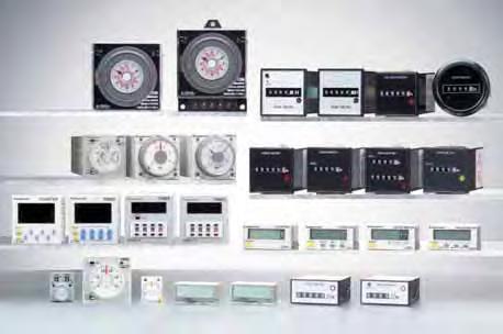
Timers/Time Switches/Counters/Hour Meters
|
|
|
- Russell Dickerson
- 5 years ago
- Views:
Transcription
1 0 0 imers/ime Switches/Counters/Hour Meters


2 MUI-RANGE ANAOG IMER PMS imers PMS Features. Economic pricing that promptly reflects market demands Remarkable economic pricing is implemented in pursuit of cost performance.. Output contacts switchable between timed out C and timed out C/Instantaneous C he timed out C/Instantaneous C output contact enables the efficient addition of self-maintenance circuits.. different time ranges selectable on a single unit Five types of timers cover the full range of time settings from second to 0 hours.. Equipped with zero-setting instantaneous output Set the dial all the way to 0 for instantaneous operation, so circuit testing can be easily accomplished.. Compliant with U, c-u and CE. Product types ype /////// Contact arrangement ime range voltage Part No. PMS Multi-range imer A type PMS Multi-range imer B type PMS Multi-range timer C type PMS Multi-range imer D type PMS Multi-range imer E type Power -delay.d.: imed-out C INS.: imed-out C Instantaneous C (Selected by front switch) s/0s/min/0min ( time ranges selectable) s/0s/min/0min ( time ranges selectable) s/0s/min/0min ( time ranges selectable) min/0min/h/0h ( time ranges selectable) min/0min/h/0h ( time ranges selectable) Parts name he PMS Multi-Range timer allows time units and output contacts to be selected via front switches. 00 to 0V AC PMS-AC0M-AC0V 00 to 0V AC PMS-AC0M-AC0V V DC PMS-AC0M-DCV V DC PMS-AC0M-DCV 00 to 0V AC PMS-AC0M-AC0V 00 to 0V AC PMS-AC0M-AC0V V DC PMS-AC0M-DCV V DC PMS-AC0M-DCV 00 to 0V AC PMS-AC0M-AC0V 00 to 0V AC PMS-AC0M-AC0V V DC PMS-AC0M-DCV V DC PMS-AC0M-DCV 00 to 0V AC PMS-AC0H-AC0V 00 to 0V AC PMS-AC0H-AC0V V DC PMS-AC0H-DCV V DC PMS-AC0H-DCV 00 to 0V AC PMS-AC0H-AC0V 00 to 0V AC PMS-AC0H-AC0V V DC PMS-AC0H-DCV V DC PMS-AC0H-DCV Output contact selector ime range selector ime unit selector
3 PMS Specifications Item Rating Notes). Unless otherwise specified, the measurement conditions at the maximum scale time standard are specified to be the rated operating voltage (within % ripple factor for DC), 0 C F ambient temperature, and s power off time.. For the s range, the tolerance for each specification becomes ±0ms. Applicable standard Safety standard EN- Pollution Degree /Overvoltage Category III EMC (EMI)EN000-- Radiation interference electric field strength Noise terminal voltage (EMS)EN000-- Static discharge immunity RF electromagnetic field immunity EF/B immunity ype EN0 Group ClassA EN0 Group ClassA EN000-- EN000-- EN000-- PMS Multi-range imer Rated operating voltage 00 to 0V AC 00 to 0V AC V DC V DC Rated frequency 0/0 Hz Rated power consumption Output rating mode ime range A type B type C type D type E type Approx..0VA/.VA (at 00V AC) Approx..VA/.VA (at 0V AC) Approx..VA/.VA (at 00V AC) Approx..W Approx..W Approx..VA/9.VA (at 0V AC) A 0V AC (resistive load) Power -delay s/0s/min/0min ( time ranges selectable) s/0s/min/0min ( time ranges selectable) s/0s/min/0min ( time ranges selectable) min/0min/h/0h ( time ranges selectable) min/0min/h/0h ( time ranges selectable) time fluctuation ±% (power off time change at the range of 0.s to h) ime accuracy Note) Setting error ±% (Full-scale value) Voltage error ±% (at the operating voltage changes between to 0%) emperature error ±% (at 0 C ambient temp. at the range of 0 to +0 C + to + F).D.: imed-out Form C Contact arrangement INS.: imed-out Form C, instantaneous Form C Contact Contact resistance (Initial value) Max. 00mΩ (at A V DC) (Selected by front switch) Contact material Silver alloy ife Mechanical (contact) Min. 0 Electrical (contact) Min. 0 (at raed control capacity) Allowable operating voltage range to 0% of rated operating voltage Min. 00MΩ Between live and dead metal parts (At 00V DC) Insulation resistance (Initial value) Between input and output Between contacts of different poles Between contacts of same pole Electrical function,000vrms for min Between live and dead metal parts Breakdown voltage (Initial value),000vrms for min Between input and output,000vrms for min Between contacts of different poles,000vrms for min Between contacts of same pole Min. power off time 00 ms Max. temperature rise C F Mechanical function Vibration resistance Functional 0 to Hz: cycle/min double amplitude of 0.mm (0min on axes) Destructive 0 to Hz: cycle/min double amplitude of 0.mm (h on axes) Shock resistance Functional Min. 9m/s ( times on axes) Destructive Min. 90m/s ( times on axes) Ambient temperature 0 to +0 C + to + F condition Ambient humidity 0 to %RH (non-condensing) Atmospheric pressure 0 to,00hpa Ripple factor (DC type) 0% Others Weight Approximately 0 g.0 oz kv contact kv air 0 V/m AM modulation (0 MHz to GHz) 0 V/m pulse modulation (9 MHz to 90 MHz) kv (power supply line) Surge immunity Conductivity noise immunity Power frequency magnetic field immunity Voltage dip/instantaneous stop/voltage fluctuation immunity EN000-- kv (power line) EN V/m AM modulation (0. MHz to 0 MHz) EN A/m (0 Hz) EN ms, 0% (rated voltage) 00 ms, 0% (rated voltage),000 ms, 0% (rated voltage),000 ms, 9% (rated voltage)
 Panel mount dimensions (with mounting frame) Mounting frame A-DA (Sold separately) Panel cut out dimensions Standard cut out dimensions are shown")
4 PMS Dimension (Unit: mm inch) olerance: ±0. ±.00 Surface mount dimensions DIN rail terminal block A-DFK (Sold separately).. Device installation rail A-DA (Sold separately) Panel mount dimensions (with mounting frame) Mounting frame A-DA (Sold separately) Panel cut out dimensions Standard cut out dimensions are shown below. Use mounting frame (A-DA) and rubber gasket (AC00) Min Min Rear terminal socket A0 (Sold separately) Panel (hickness to. mm.09 to. inch) Adjacent mounting A +0. A = ( n.) 0 A = (.90 n.09) erminal layouts and wiring diagrams. D. I N S..D.: imed-out Form C INS.: imed-out Form C, instantaneous Form C * Selected by front switch MODE NO NC COM voltage NC NO COM Notes:. voltage signs in parentheses ( ) indicate the polarity of the DC type.. is a time delay contact. is an instantaneous contact. Operation mode..d. mode. INS. mode Power supply ime out ( contact) or OP.ED Power supply ime out ( contact) ime out ( contact) OP.ED Note: Keep 0.s or more for power off time.
5 PMS Precautions during usage. Avoid locations subject to flammable or corrosive gases, excessive dust, oil, vibrations, or excessive shocks.. Since the main-unit is made of polycarbonate resin, avoid contact with or use in environments containing methyl alcohol, benzene, thinners, and other organic solvents; and ammonia, caustic sodas, and other alkaline substances.. Power supply superimposed surge protector Although a surge protector will withstand standard-waveform voltage with the values in the next table, anything above this will destroy the internal circuit. You should therefore use a surge absorber. V DC 00 to 0 V AC V DC 00 to 0 V AC 00 V,000 V Surge waveform [±(. 0) µs uni-polar full wave voltage]. In order to maintain the characteristics, do not remove the timer case.. When installing the panel, use the AA mounting frame (Sold separately).. If you change the operating voltage, be sure not to allow leak current into the timer.. Avoid leaving the unit powered continuously. eaving the unit powered up with output set to continuously for a long period of time (about month or more) will wear out the electronic components. If you will be keeping it powered continuously, combine with a relay to create the circuit shown below: R R R. he timer setting dial should only be turned within the range indicated on the dial face. urning it too far may break the stopper and cause damage to internal components. Acquisition of CE marking Please abide by the conditions below when using in applications that comply with EN-.. Overvoltage category III, pollution level. he load connected to the output contact should have basic insulation. his timer is protected with basic insulation and can be doubleinsulated to meet EN/IEC requirements by using basic insulation on the load.. Please use a power supply that is protected by an overcurrent protection device which complies with the EN/ IEC standard (example: 0 V A fuse, etc.).. You must use a terminal socket or socket for the installation. Do not touch the terminals or other parts of the timer when it is powered. When installing or un-installing, make sure that no voltage is being applied to any of the terminals.. Do not use this timer as a safety circuit. For example when using a timer in a heater circuit, etc., provide a protection circuit on the machine side.
6 DIN SIZE MUI-RANGE ANAOG IMER PMH-A/S/M PMH-A PMH-S PMH-M U File No.: E CSA File No.: R Pin type.. mm inch Screw terminal type Features. 00-0V AC free-voltage input, -V DC type available. Short body.mm. inch (screw terminal type). Front panel of IP type is protected against water-splash and dust. Built-in s type is used for easy wiring and reducing additional cost for accessories.. 0 setting instantaneous output operation. Multiple time ranges s to 00 h (Max.). different operation modes: (PMH-A). Compliant with U/CSA, CE and OYD Product types ype PMH-A PMH-S PMH-M Operation mode operation modes Pulse -delay Pulse Flicker Pulse -flicker Differential /-delay () () Signal -delay Pulse One-shot Pulse One-cycle Power -delay operation modes (With instantaneous contact) Power -delay Power Flicker Power -flicker Power One-shot Power One-cycle Contact arrangement Relay imed-out Form C Relay imed-out Form C Relay imed-out Form C Instantaneous Form C ime range selectable ranges s to 00h Protective construction IP IP0 IP IP0 IP IP0 Rated operating voltage 00 to 0V AC to V DC V AC/DC V DC 00 to 0V AC to V DC V AC/DC V DC 00 to 0V AC to V DC V AC/DC V DC 00 to 0V AC to V DC V AC/DC V DC 00 to 0V AC to V DC V AC/DC V DC 00 to 0V AC to V DC V AC/DC V DC erminal type pins pins pins pins pins pins pins pins If you use this timer under harsh environment, please order above sealed type (IP type). IP type Protection dust and water jet splay on the front face. Part number PMHA-H-AC0VW PMHA-H-AC0VSW PMHA-H-DCVW PMHA-H-DCVSW PMHA-H-VW PMHA-H-VSW PMHA-H-DCVW PMHA-H-DCVSW PMHA-H-AC0V PMHA-H-AC0VS PMHA-H-DCV PMHA-H-DCVS PMHA-H-V PMHA-H-VS PMHA-H-DCV PMHA-H-DCVS PMHS-H-AC0VW PMHS-H-AC0VSW PMHS-H-DCVW PMHS-H-DCVSW PMHS-H-VW PMHS-H-VSW PMHS-H-DCVW PMHS-H-DCVSW PMHS-H-AC0V PMHS-H-AC0VS PMHS-H-DCV PMHS-H-DCVS PMHS-H-V PMHS-H-VS PMHS-H-DCV PMHS-H-DCVS PMHM-H-AC0VW PMHM-H-AC0VSW PMHM-H-DCVW PMHM-H-DCVSW PMHM-H-VW PMHM-H-VSW PMHM-H-DCVW PMHM-H-DCVSW PMHM-H-AC0V PMHM-H-AC0VS PMHM-H-DCV PMHM-H-DCVS PMHM-H-V PMHM-H-VS PMHM-H-DCV PMHM-H-DCVS
7 PMH-A/S/M ime range ime unit Scale sec min hrs 0h 0.s to s 0. min to min 0.h to h.0h to 0h Control 0.s to s 0. min to min 0.h to h h to 0h 0 time range.0s to 0s.0 min to 0 min.0h to 0h 0h to 00h 0 s to 0s min to 0 min h to 0h 0h to 00h Note: 0 setting is for instantaneous output operation. PMH-A/PMH-S/PMH-M All types of PMH timer have multi-time range. time ranges are selectable. s to 00h (Max. range) is controlled. Specifications Item Rating ime accuracy Note:) Contact ife Electrical function Mechanical function condition Others Rated operating voltage Rated frequency Rated power consumption Rated control capacity mode ime range time fluctuation Setting error Voltage error emperature error Contact arrangement ype Contact resistance (Initial value) Contact material Mechanical (contact) Electrical (contact) Allowable operating voltage range Insulation resistance (Initial value) Breakdown voltage (Initial value) Min. power off time Max. temperature rise Functional Vibration resistance Destructive Functional Shock resistance Destructive Ambient temperature Ambient humidity Atmospheric pressure Ripple factor (DC type) Protective construction Weight PMH-A Pulse -delay Pulse Flicker Pulse -Flicker Differential /-delay () () Signal -delay Pulse One-shot Pulse One-cycle PMH-S 00 to 0V AC, to V DC, V DC, V AC/DC 0/0Hz common (AC operating type) Approx. 0VA (00 to 0V AC) Approx..VA (V AC) Approx..W (V DC, V DC, to V DC) A 0V AC (resistive load) Power -delay PMH-M Power -delay Power Flicker Power -flicker Power One-shot Power One-cycle (with instantaneous contact) s to 00h (Max.) time ranges switchable ±0.% (power off time change at the range of 0.s to h) ±% (Full-scale value) ±0.% (at the operating voltage changes between to 0%) ±% (at 0 C ambient temp. at the range of 0 to +0 C + to + F) imed-out Form C imed-out Form C Instantaneous Form C Max. 00mΩ (at A V DC) Silver alloy Au flash on Silver alloy 0 0 (at rated control capacity) to 0% of rated operating voltage (at 0 C coil temp.) Between live and dead metal parts Between input and output Min. 00MΩ (At 00V DC) Between contacts of different poles Between contacts of same pole,000vrms for min Between live and dead metal parts,000vrms for min Between input and output,000vrms for min Between contacts of different poles,000vrms for min Between contacts of same pole 00ms C F C 9 F 0 to Hz: cycle/min double amplitude of 0.mm (0min on axes) 0 to Hz: cycle/min double amplitude of 0.mm (h on axes) Min. 9m/s ( times on axes) Min. 90m/s ( times on axes) 0 to +0 C + to + F 0 to %RH (at 0 C F, non-condensing) 0 to,00hpa 0% IP on front panel (using rubber gasket AC00) <only for IP type> 00g. oz (Pin type) 0g.0 oz ( type) Note: ) Unless otherwise specified, the measurement conditions at the maximum scale time standard are specified to be the rated operating voltage (within % ripple factor for DC), 0 C F ambient temperature, and s power off time. ) For the s range, the tolerance for each specification becomes ±0ms.
 voltage ( ) type imed-out Form C Instantaneous Form C 9 0 Stop input Reset input Start input 9 0 (+) voltage ( ) PMH-S Pin type imed-out Form C ) DC ype ype PMH-A PMH-S PMH-M")
8 erminal layouts and Wiring diagrams PMH-A Pin type imed-out Form C Reset input Start input Stop input 9 0 voltage ( ) (+) PMH-M Pin type imed-out Form C Instantaneous Form C voltage ( ) (+) type imed-out Form C (+) voltage ( ) type imed-out Form C Instantaneous Form C 9 0 Stop input Reset input Start input 9 0 (+) voltage ( ) PMH-S Pin type imed-out Form C ) DC ype ype PMH-A PMH-S PMH-M voltage ( ) (+) ) Contact imed-out contact type imed-out Form C Pin Connect the terminal to negative ( ), and the terminal to positive (+). Connect the terminal to negative ( ), and the terminal to positive (+). Instantaneous contact PMH-A/S/M Connect the terminal x to negative ( ), and the terminal z to positive (+). ) Voltage should not be applied to the various inputs (reset, start, and stop) of the PMH-A multi-range timer. hese inputs should be input without voltage. (+) voltage ( ) 9 0 Parts name PMH-S PMH-A PMH-M Power indicator ED ime indicator window ime unit indicator Output indicator ED Hand Set dial Operation mode indicator Operation mode selector Selectable from operation modes : Power -delay F : Power flicker FO : Power -flicker OS : Power One-shot OC : Power One-cycle ime range selector time settings selectable ( s to 00 h) s s 0s 0s min min 0min 0min h h 0h 0h 0h 0h 00h 00h Instantaneous output area When the hand is in this area, instantaneous operation starts. Operation mode selector Selectable from operation modes : Pulse -delay F : Pulse Flicker FO : Pulse -flicker OF : Differential /-delay () SF : Signal -delay OS : Pulse One-shot OF : Differential /-delay () OC : Pulse One-cycle
9 PMH-A/S/M Dimensions PMH- type (Flush mount) Pin type (Flush mount/surface mount) mm inch olerance: ±0. ± dia.. dia dia.. dia... Panel mount dimensions (with mounting frame) type Pin type Rubber gasket AC 00 (attached) Panel Mounting frame A-DA (attached) Rubber gasket AC00 Panel Mounting frame A-DA (Sold separately) (-pin).0 (-pin) Rear terminal socket A0 (-pin: sold separately) A0 (-pin: sold separately) Surface mount dimensions Pin type 9. (-pin). 0.0 (-pin).09 Din rail socket A-DFK (-pin: sold separately) A-DFK (-pin: sold separately) Mounting rail A-DA Panel cut out dimensions Standard cut out dimensions are shown below. Use mounting frame (A-DA) and rubber gasket (AC00) Min. 0.0 Min. 0.0 Adjacent mounting A A = ( n.) A = (.90 n.09) Note). he proper thickness of mounting panel is between to mm.. Adjacent mount is less water-resistant.
10 Operation mode PMH-A Operation type Explanation ime chart Pulse -delay Pulse Flicker F Pulse -flicker FO If using a time-limit start when the power is turned on, and a reset when the power is turned off, pins to (screw-tightening pins x and c) should be shorted ahead of time. urn the operation mode selector switch to the position. If pins to (screw-tightening pins x and c) are shorted (the start input is turned on) with the power supply on, the output will go on after the set time has elapsed. If the power supply is turned off, or pins to (screw-tightening pins x to v) are shorted (the reset input is turned on), a reset is carried out. Note) During time-limited operation, the time-limited operation is stopped while the pins to (screw-tightening pins x to b) are being shorted (the stop input is on). When the pins are released, time-limited operation resumes. If using a time-limit start when the power is turned on, and a reset when the power is turned off, pins to (screw-tightening pins x and c) should be shorted ahead of time. urn the operation mode selector switch to the F position. When pins to (screw-tightening pins x and c) are shorted (the start input is turned on) with the power supply on, the limited time interval begins, and the output goes on after the set time has elapsed. After the output has gone on, it goes off when the set time has elapsed, and this process is subsequently repeated. If the power supply is turned off, or pins to (screw-tightening pins x to v) are shorted (the reset input is turned on), a reset is carried out. Note) During time-limited operation, the time-limited operation is stopped while the pins to (screw-tightening pins x to b) are being shorted (the stop input is on). When the pins are released, time-limited operation resumes. If using a time-limit start when the power is turned on, and a reset when the power is turned off, pins to (screw-tightening pins x and c) should be shorted ahead of time. urn the operation mode selector switch to the FO position. When pins to (screw-tightening pins x and c) are shorted (the start input is turned on) with the power supply on, the output goes on, and after the set time has elapsed, it goes off. his process is subsequently repeated. If the power supply is turned off, or pins to (screw-tightening pins x to v) are shorted (the reset input is turned on), a reset is carried out. Note) During time-limited operation, the time-limited operation is stopped while the pins to (screw-tightening pins x to b) are being shorted (the stop input is on). When the pins are released, time-limited operation resumes. Power supply Start Reset Stop ime out ( contact) OP. ED POWER ED Power supply Note: Start Reset Stop ime out ( contact) OP. ED POWER ED Power supply Start Note: Reset Stop ime out ( contact) OP. ED POWER ED PMH-A/S/M ED lighting ED flickering : Setting time t, t, ta, tb< t+t= t t ED lighting or No ED lighting ta t t tb ED lighting or No ED lighting ta t t tb Differential /-delay () OF Signal -delay SF urn the operation mode selector switch to the OF position. When pins to (screw-tightening pins x and c) are shorted (the start input is turned on) with the power supply on, the output goes on, and after the set time has elapsed, it goes off. Also, when pins to are released (the start input goes off), the output goes on, and after the set time has elapsed, it goes off. If the status of pins to (screw-tightening pins x and c) changes during the time-limit interval (the start input goes from on to off, or from off to on), the time-limit interval is restarted from the point at which the change took place. If the power supply is turned off, or pins to (screw-tightening pins x to v) are shorted (the reset input is turned on), a reset is carried out. Note) During time-limited operation, the time-limited operation is stopped while the pins to (screw-tightening pins x to b) are being shorted (the stop input is on). When the pins are released, time-limited operation resumes. urn the operation mode selector switch to the SF position. When pins to (screw-tightening pins x and c) are shorted (the start input is turned on) with the power supply on, the output goes on, and when pins to (screw-tightening pins x and c) are released (the start input is turned off), the time limit interval begins. After the set time has elapsed, the output goes off. If start input is entered at any point during the time limit interval, the time limit interval is reset. Note) During time-limited operation, the time-limited operation is stopped while the pins to (screw-tightening pins x to b) are being shorted (the stop input is on). When the pins are released, time-limited operation resumes. Power supply Start Reset Stop t t ta tb ime out ( contact) OP. ED Restart POWER ED Note: ED lighting or No ED lighting Power supply Start Reset Stop ta tb ime out ( contact) OP. ED POWER ED Note: Keep 0.s or more for power off time. Keep 0.0s or more for start, stop, reset input time. Note: ED lighting or No ED lighting
11 PMH-A/S/M Operation type Explanation ime chart Pulse One-shot OS Differential /-delay () OF Pulse One-cycle OC If using a time-limit start when the power is turned on, and a reset when the power is turned off, pins to (screw-tightening pins x and c) should be shorted ahead of time. urn the operation mode selector switch to the OS position. When pins to (screw-tightening pins x and c) are shorted (the start input is turned on) with the power supply on, the output goes on for the set time limit interval. If the power supply is turned off, or pins to (screw-tightening pins x to v) are shorted (the reset input is turned on), a reset is carried out. Note) During time-limited operation, the time-limited operation is stopped while the pins to (screw-tightening pins x to b) are being shorted (the stop input is on). When the pins are released, time-limited operation resumes. urn the operation mode selector switch to the OF position. When pins to (screw-tightening pins x and c) are shorted (the start input is turned on) with the power supply on, the time limit interval begins, and after the set time interval has elapsed, the output goes on. Also, when pins to are released (the start input goes off), the time limit interval begins, and after it has elapsed, the output goes off. If the status of pins to (screw-tightening pins x and c) changes during the time-limit interval (the start input goes from on to off, or from off to on), the time limit interval is restarted from the point at which the change took place. If the power supply is turned off, or pins to (screw-tightening pins x to v) are shorted (the reset input is turned on), a reset is carried out. Note) During time-limited operation, the time-limited operation is stopped while the pins to (screw-tightening pins x to b) are being shorted (the stop input is on). When the pins are released, time-limited operation resumes. If using a time-limit start when the power is turned on, and a reset when the power is turned off, pins to (screw-tightening pins x and c) should be shorted ahead of time. urn the operation mode selector switch to the OC position. When pins to (screw-tightening pins x and c) are shorted (the start input is turned on) with the power supply on, the output goes on after the set time limit interval has elapsed. After it has gone on, it goes off after one pulse (approximately 0. seconds). If the power supply is turned off, or pins to (screw-tightening pins x to v) are shorted (the reset input is turned on), a reset is carried out. Note) During time-limited operation, the time-limited operation is stopped while the pins to (screw-tightening pins x to b) are being shorted (the stop input is on). When the pins are released, time-limited operation resumes. Note: Keep 0.s or more for power off time. Keep 0.0s or more for start, stop, reset input time. PMH-S Operation type Explanation ime chart Power -delay ime limit contact relay When the power supply is turned on, the output goes on after the set time interval has elapsed. When the power supply is turned off, a reset is carried out. Power supply Start Reset Stop ime out ( contact) OP. ED POWER ED Power supply Start Note: Reset Stop ime out ( contact) OP. ED POWER ED Power supply Start Note: Reset Stop ime out ( contact) OP. ED Power supply POWER ED ime out ( contact) OP. ED POWER ED t t ta ED lighting or No ED lighting t t ta tb Restart ED lighting or No ED lighting t ta t t t tb One pulse time (t): Approx. 0.s Note: ED lighting or No ED lighting ED lighting : Setting time ED flickering PMH-M Operation type Explanation ime chart Power -delay Power Flicker F Power -flicker FO Power One-shot OS Power One-cycle OC urn the operation mode selector switch to display the various operations. When the power supply is turned on, the time limit interval begins, and operation is carried out. When the power supply is turned off, a reset is carried out. Power -delay Power supply ime out ( contact) Instantaneous contact ( contact) OP. ED POWER ED Note: Keep 0.s or more for power off time. PMH-M timers do not have each input which is start, reset and stop.
12 PMH-SD/SDM DIN SIZE ANAOG SAR ( )-DEA ( ) IMERS PMH-SD/SDM U File No.: E CSA File No.: R mm inch Features. Select four types of time ranges between 0. s and 00 s on a single unit.. Select between five types of time ranges between 0.0 s and 0. s for the - switching times.. here is a - switching indicator so you can check the operation at a glance.. he AC free power supply and shorter body make it easier to use.. Compliant with U, CSA, CE and OYD. Specifications Item Rating ime accuracy Note:) Contact ife Electrical function Mechanical function condition Others ype Rated operating voltage Rated frequency Rated power consumption Rated control capacity Operation mode operation control time range - switching time Operation time fluctuation Setting error Voltage error emperature error Contact arrangement Contact resistance (Initial value) Contact material Mechanical (contact) Electrical (contact) Allowable operating voltage range Insulation resistance (Initial value) Breakdown voltage (Initial value) Min. power off time Max. temperature rise Functional Vibration resistance Destructive Functional Shock resistance Destructive Ambient temperature Ambient humidity Atmospheric pressure Protective construction Weight PMH-SD/SDM 00 to 0V AC, V AC 0/0Hz common Approx. VA (00 to 0V AC), Approx..VA (V AC) A 0V AC (resistive load) - star-delta switching (Power -delay) s to 00s, time ranges switchable 0.0, 0., 0., 0., 0.s ( time range selectable) ±0.% (power off time change at the range of 0.s to h) ±% (Full-scale value) ±0.% (at the operating voltage changes between to 0%) ±% (at 0 C ambient temp. at the range of 0 to +0 C + to + F) Star ( ) side: imed-out Form A, Delta ( ) side: imed-out Form A Instantaneous: Form A (Instantaneous for PMH-SDM type only) Max. 00mΩ (at A V DC) Au flash on Silver alloy 0 0 (at rated control capacity) to 0% of rated operating voltage (at 0 C coil temp.) Between live and dead metal parts Between input and output Min. 00MΩ (At 00V DC) Between contacts of different poles (*) Between contacts of same pole,000vrms for min Between live and dead metal parts,000vrms for min Between input and output,000vrms for min Between contacts of different poles (*),000Vrms for min Between contacts of same pole 00ms C F 0 to Hz: cycle/min double amplitude of 0.mm (0min on axes) 0 to Hz: cycle/min double amplitude of 0.mm (h on axes) Min. 9m/s ( times on axes) Min. 90m/s ( times on axes) 0 to +0 C + to + F Max. %RH (non-condensing) 0 to,00hpa IP on front panel (using rubber gasket AC00) <only for IP type> 00g. oz (Pin type), 0g.0 oz ( type) Notes: ) Unless otherwise specified, the measurement conditions at the maximum scale time standard are specified to be the rated operating voltage, 0 C F ambient temperature, and s power off time. ) For the s range, the tolerance for each specification becomes ±0ms. ) Between contacts of different poles for PMH-SDM type only.
13 PMH-SD/SDM ime range ime range unit ime range Product types Operation Protective Rated operating erminal ype Contact arrangement ime range Part number mode construction voltage type PMH-SD Star ( )-Delta ( ) switching PMH-SDM Star ( )-Delta ( ) switching (Instantaneous contact) PMH-SD Star ( )-Delta ( ) switching PMH-SDM Star ( )-Delta ( ) switching (Instantaneous contact) Star ( )- Delta ( ) switching Relay imed-out side: Form A side: Form A Relay imed-out side: Form A side: Form A Instantaneous: Form A Relay imed-out side: Form A side: Form A Relay imed-out side: Form A side: Form A Instantaneous: Form A selectable ranges over s to 00s ( - switching time: 0.0, 0., 0., 0., 0.s) erminal layouts and Wiring diagrams Pin type No instantaneous contact (s) - switching time (s) 0. to to 0 to 0 0 to 00 With instantaneous contact IP IP0 00 to 0V AC V AC 00 to 0V AC V AC 00 to 0V AC V AC 00 to 0V AC V AC type No instantaneous contact With instantaneous contact PMHSD-S-AC0VW PMHSD-S-AC0VSW PMHSD-S-ACVW PMHSD-S-ACVSW PMHSDM-S-AC0VW PMHSDM-S-AC0VSW PMHSDM-S-ACVW PMHSDM-S-ACVSW PMHSD-S-AC0V PMHSD-S-AC0VS PMHSD-S-ACV PMHSD-S-ACVS PMHSDM-S-AC0V PMHSDM-S-AC0VS PMHSDM-S-ACV PMHSDM-S-ACVS voltage 9 0 voltage voltage voltage 9 0 side time-delay contact side time-delay contact Instantaneous contact (PMH-SDM type) side time-delay contact side time-delay contact Instantaneous contact (PMH-SDM type) Dimensions mm inch dia.. dia... Operation Power supply Instantaneous contact side Contact side Contact t t t t: operation time ( indicator ED lights) t: switching time t: operation time ( indicator ED lights)

14 PMH-F DIN SIZE ANAOG MUIRANGE POWER -DEAY IMERS PMH-F mm inch U File No.: E CSA File No.: R99 Features. Switch operation times between three types of time ranges of s to 0 s and min to 0 min.. Instantaneous reset available.. he shorter body makes it easier to use.. Compliant with U, CSA, CE and OYD. Specifications Item Rating ime accuracy * Contact ife Electrical function Mechanical function condition Others Rated operating voltage Rated frequency Rated power consumption ype Rated control capacity Operation mode ime range Operation time fluctuation Setting error Voltage error emperature error Contact arrangement Contact resistance (Initial value) Contact material Mechanical (contact) Electrical (contact) Allowable operating voltage range Insulation resistance (Initial value) Breakdown voltage (Initial value) Min. power supply width Min. reset time Max. temperature rise Functional Vibration resistance Destructive Functional Shock resistance Destructive Ambient temperature Ambient humidity Atmospheric pressure Ripple factor (DC type) Protective construction Weight PMH-F PMH-FR PMH-FR 00 to 0V AC, 00 to 0V AC, V AC, V DC, V DC 0/0Hz common (AC operating type) Approx..VA (00 to 0V AC, 00 to 0V AC), Approx..VA (V AC) Approx..W (V DC, V DC) A 0V AC (resistive load) Power -delay Power -delay (with reset) s to 0s: range switchable min to 0 min: range selectable ±0.% ±% (Full-scale value) ±0.% (at the operating voltage changes between to 0%) ±% (at 0 C ambient temp. at the range of 0 to +0 C + to + F) imed-out Form C imed-out Form C imed-out Form C Max. 00mΩ (at A V DC) Au flash on Silver alloy 0 0 (at rated control capacity) to 0% of rated operating voltage (at 0 C coil temp.), 90 to 0% (DC ype) Between live and dead metal parts Between input and output Min. 00MΩ (At 00V DC) Between contacts of different poles (*) Between contacts of same pole,00vrms for min Between live and dead metal parts,00vrms for min Between input and output,000vrms for min Between contacts of different poles (*) 0Vrms for min Between contacts of same pole s range type: 00ms min range type: s 0ms C F 0 to Hz: cycle/min double amplitude of 0.mm (0min on axes) 0 to Hz: cycle/min double amplitude of 0.mm (hr on axes) Min. 9m/s ( times on axes) Min. 90m/s ( times on axes) 0 to +0 C + to + F 0 to %RH (non-condensing) 0 to,00hpa 0% IP on front panel (using rubber gasket AC00) <only for IP type> 00g. oz (Pin type), 0g.0 oz ( type) *Notes: ) Unless otherwise specified, the measurement conditions at the maximum scale time standard are specified to be the rated operating voltage (within % ripple factor for DC), 0 C F ambient temperature. ) For the s range, the tolerance for each specification becomes ±0ms. When the power goes on, in rush current (0.A) flows. Cautions should be taken. he minimum power supplying time after forced reset input is s or more. ) Between contacts of different pools for PMH-F, PMH-FR types only.
15 PMH-F ime range ime range unit ime range 0 s range type 0.0s to s 0.s to s 0.s to 0s min range type 0.0 min to min 0. min to min 0. min to 0 min Product types Operation Protective Rated operating erminal ype Contact arrangement ime range Part number mode construction voltage type PMH-F PMH-FR Power -delay (without reset) Power -delay (with instantaneous reset) Relay imed-out Form C Relay imed-out Form C selectable time ranges over s to 0s selectable time ranges over min to 0 min selectable time ranges over s to 0s selectable time ranges over min to 0 min selectable time ranges over s to 0s selectable time ranges over min to 0 min selectable time ranges over s to 0s selectable time ranges over min to 0 min IP IP0 IP IP0 00 to 0V AC 00 to 0V AC V AC V DC V DC 00 to 0V AC 00 to 0V AC V AC V DC V DC 00 to 0V AC 00 to 0V AC V AC V DC V DC 00 to 0V AC 00 to 0V AC V AC V DC V DC 00 to 0V AC 00 to 0V AC V AC V DC V DC 00 to 0V AC 00 to 0V AC V AC V DC V DC 00 to 0V AC 00 to 0V AC V AC V DC V DC 00 to 0V AC 00 to 0V AC V AC V DC V DC PMHF-S-AC0VW PMHF-S-AC0VW PMHF-S-ACVW PMHF-S-DCVW PMHF-S-DCVW PMHF-M-AC0VW PMHF-M-AC0VW PMHF-M-ACVW PMHF-M-DCVW PMHF-M-DCVW PMHF-S-AC0V PMHF-S-AC0V PMHF-S-ACV PMHF-S-DCV PMHF-S-DCV PMHF-M-AC0V PMHF-M-AC0V PMHF-M-ACV PMHF-M-DCV PMHF-M-DCV PMHFR-S-AC0VW PMHFR-S-AC0VW PMHFR-S-ACVW PMHFR-S-DCVW PMHFR-S-DCVW PMHFR-M-AC0VW PMHFR-M-AC0VW PMHFR-M-ACVW PMHFR-M-DCVW PMHFR-M-DCVW PMHFR-S-AC0V PMHFR-S-AC0V PMHFR-S-ACV PMHFR-S-DCV PMHFR-S-DCV PMHFR-M-AC0V PMHFR-M-AC0V PMHFR-M-ACV PMHFR-M-DCV PMHFR-M-DCV
16 PMH-FR PMH-F Operation Protective Rated operating erminal ype Contact arrangement ime range Part number mode construction voltage type Power -delay (with instantaneous reset) Dimensions type (Flush mount) Relay imed-out Form C selectable time ranges over s to 0s selectable time ranges over min to 0 min IP IP0 IP IP0 00 to 0V AC 00 to 0V AC V AC V DC V DC 00 to 0V AC 00 to 0V AC V AC V DC V DC 00 to 0V AC 00 to 0V AC V AC V DC V DC 00 to 0V AC 00 to 0V AC V AC V DC V DC Pin type (Flush mount/surface mount) pins pins pins pins pins pins pins pins pins pins pins pins pins pins pins pins pins pins pins pins PMHFR-S-AC0VW PMHFR-S-AC0VSW PMHFR-S-AC0VW PMHFR-S-AC0VSW PMHFR-S-ACVW PMHFR-S-ACVSW PMHFR-S-DCVW PMHFR-S-DCVSW PMHFR-S-DCVW PMHFR-S-DCVSW PMHFR-S-AC0V PMHFR-S-AC0VS PMHFR-S-AC0V PMHFR-S-AC0VS PMHFR-S-ACV PMHFR-S-ACVS PMHFR-S-DCV PMHFR-S-DCVS PMHFR-S-DCV PMHFR-S-DCVS PMHFR-M-AC0VW PMHFR-M-AC0VSW PMHFR-M-AC0VW PMHFR-M-AC0VSW PMHFR-M-ACVW PMHFR-M-ACVSW PMHFR-M-DCVW PMHFR-M-DCVSW PMHFR-M-DCVW PMHFR-M-DCVSW PMHFR-M-AC0V PMHFR-M-AC0VS PMHFR-M-AC0V PMHFR-M-AC0VS PMHFR-M-ACV PMHFR-M-ACVS PMHFR-M-DCV PMHFR-M-DCVS PMHFR-M-DCV PMHFR-M-DCVS mm inch oletance: ±0. ± dia.. dia dia.. dia...
17 PMH-F erminal layouts and Wiring diagrams PMH-F (without reset input) Pin type ime-out Form C PMH-FR (with reset input) Pin type ime-out Form C, with reset input PMH-FR (with reset input) Pin type ime-out Form C, with reset input Reset input Reset input 9 0 voltage ( ) (+) voltage ( ) (+) voltage ( ) (+) Screw-tightening pin type he PMH-FR should be used for the timelimit C. Screw-tightening pin type he PMH-FR should be used for the timelimit C and to connect reset input. type ime-out Form C, with reset input 9 0 (+) voltage ( ) Reset input PMH-F (with reset) input conditions. Contact input (pin type example). Non-contact input (pin type example) Reset input PMH-FR PMH-FR Reset input Use a contact with good contact reliability for the input. Contact bounce can lead to erroneous operation of the timer, so use a contact with short bounce time. Make the resistance between terminals for a short circuit less than k-ohms. Make the resistance between terminals for an open circuit greater than 00k-ohms. PMH-FR Reset input Photo-coupler Reset input PMH-FR Photo-coupler Be sure to use a photocoupler for non-contact input. Check that Vce = 0.V Max. when. Operation PMH-F (without reset input) PMH-FR/FR (with reset input) r r Note: s r Note: s Power supply Power supply ime-delay contact Reset input t ime-delay contact ime-delay contact ime-delay contact t<: ime setting r: Minimum power supply application time Note: s: Min. s (ime to restart operation after reset input is set to : both second type and minute type)
18 PMH-W DIN SIZE ANAOG MUI-ANGE CYCIC WIN IMERS PMH-W U File No.: E CSA File No.: R mm inch Features. A single twin timer unit that repeats (variable) /.. Multiple ranges with a 0. s to 00 h time specification on a single unit.. he output / operation is indicated by red and green ED s. It s easy to check the operation at a glance.. he AC free power supply and shorter body make it easier to use.. A new screw terminal type has been added to the conventional pin type. Wiring can be done easily with a screwdriver.. Compliant with U, CSA, CE and OYD. Specifications Item Rating ime accuracy Note:) Contact ife Electrical function Mechanical function condition Others Rated operating voltage Rated frequency Rated power consumption ype Rated control capacity Operation mode ime range Operation time fluctuation Setting error Voltage error emperature error Contact arrangement Contact resistance (Initial value) Contact material Mechanical (contact) Electrical (contact) Allowable operating voltage range Insulation resistance (Initial value) Breakdown voltage (Initial value) Min. power off time Max. temperature rise Functional Vibration resistance Destructive Functional Shock resistance Destructive Ambient temperature Ambient humidity Atmospheric pressure Ripple factor (DC type) Protective construction Weight PMH-W 00 to 0V AC, to V DC, V DC, V AC/DC 0/0Hz common (AC operating type) Approx. 0VA (00 to 0V AC) Approx..VA (V AC) Approx..W (V DC, V DC, to V DC) A 0V AC (resistive load) Cyclic (-start/win operation) s to 00h time ranges switchable (, time setting individually) ±0.% (power off time change at the range of 0.s to h) ±% (Full-scale value) ±0.% (at the operating voltage changes between to 0%) ±% (at 0 C ambient temp. at the range of 0 to +0 C + to F) imed-out Form C Max. 00mΩ (at A V DC) Silver alloy 0 0 (at rated control capacity) to 0% of rated operating voltage (at 0 C coil temp.) Between live and dead metal parts Between input and output Min. 00MΩ (At 00V DC) Between contacts of different poles Between contacts of same pole,000vrms for min Between live and metal parts,000vrms for min Between input and output,000vrms for min Between contacts of different poles,000vrms for min Between contacts of same pole 00ms C F 0 to Hz: cycle/min double amplitude of 0.mm (0min on axes) 0 to Hz: cycle/min double amplitude of 0.mm (h on axes) Min. 9m/s ( times on axes) Min. 90m/s ( times on axes) 0 to +0 C + to + F 0 to %RH (non-condensing) 0 to,00hpa 0% IP on front panel (using rubber gasket AC00) <only for IP type> 0g. oz (Pin type), 0g. oz ( type) Notes: ) Unless otherwise specified, the measurement conditions at the maximum scale time standard are specified to be the rated operating voltage (within % ripple factor for DC), 0 C F ambient temperature, and s power off time. ) For the s range, the tolerance for each specification becomes ±0ms. ) As internal components may become worn when using continuous conduction, the product should be replaced periodically. 9
19 PMH-W ime range All types of PMH-W timer have multi-time range. time ranges are selectable. s to 00h (Max. range) is controlled. Scale Product types Protective Rated erminal ype Contact arrangement ime range Part number mode structure voltage type PMH-W win timer ime unit Cyclic (-start, win) Relay imed-out Form C selectable ranges (s to 00h) erminal layouts and Wiring diagrams Pin ype Cyclic timed-out relay contact: C sec min hrs 0h 0.s to s 0. min to min 0.h to h.0h to 0h Control 0.s to s 0. min to min 0.h to h h to 0h 0 time range.0s to 0s.0 min to 0 min.0h to 0h 0h to 00h 0 s to 0s min to 0 min h to 0h 0h to 00h type Cyclic timed-out relay contact: C IP IP0 00 to 0V AC to V DC V AC/DC V DC 00 to 0V AC to V DC V AC/DC V DC PMHW-H-AC0VW PMHW-H-AC0VSW PMHW-H-DCVW PMHW-H-DCVSW PMHW-H-VW PMHW-H-VSW PMHW-H-DCVW PMHW-H-DCVSW PMHW-H-AC0V PMHW-H-AC0VS PMHW-H-DCV PMHW-H-DCVS PMHW-H-V PMHW-H-VS PMHW-H-DCV PMHW-H-DCVS 9 0 voltage ( ) (+) (+) voltage ( ) Dimensions type: M. Pin type mm inch oletance: ±0. ± Operation Power supply ime-delay contact ( contact) ime-delay contact ( contact) Output - indicator : Output indicator (green) : Output indicator (orange) : set time : set time 0
![PMH SERIES MODES AND IME SEING. Operation method ) Operation mode setting [PMH-A type] operation modes are selectable with operation mode selector. urn the operation mode selector with screw driver.](/docs-images/85/92939549/images/20-0.jpg "Operation mode is shown up through the window above the mode selector. he marks are, F, FO, OF, SF, OS, OF, OC. urn the mode selector to the mark until you can check by clicking sound.")
![Confirm the mode selector position if it is correct. If the position is not stable, the timer might mis-operate. ) ime range setting [PMH series common] time ranges are selectable between s to 00h.](/docs-images/85/92939549/images/20-1.jpg "urn the time range selector with the screw driver. Clockwise turning increases the time range, and Counter-clockwise turning decrease the time range.")
20 PMH SERIES MODES AND IME SEING. Operation method ) Operation mode setting [PMH-A type] operation modes are selectable with operation mode selector. urn the operation mode selector with screw driver. Operation mode is shown up through the window above the mode selector. he marks are, F, FO, OF, SF, OS, OF, OC. urn the mode selector to the mark until you can check by clicking sound. Confirm the mode selector position if it is correct. If the position is not stable, the timer might mis-operate. ) ime range setting [PMH series common] time ranges are selectable between s to 00h. urn the time range selector with the screw driver. Clockwise turning increases the time range, and Counter-clockwise turning decrease the time range. Confirm the range selector position if it is correct. If the position is not stable, the timer might mis-operate. ) ime setting [common] o set the time, turn the set dial to a desired time within the range. Instantaneous output will be on when the dial is set to 0. When the instantaneous output is used, the dial should be set under 0 range. (Instantaneous output area) When power supply is on, the time range, setting time and operation mode cannot be changed. urn off the power supply or a reset signal is applied to set the new operation mode. If the position is not stable, the timer might mis-operate.. How to use Set ring [PMH series common] ) Fixed time setting ) ime range setting Set the desired time and put set rings Example: ime range 0s to 0s. together. Shorter time value setting Insert the rings into stopper to fix the Set the dial to 0s. time. Place the stop ring at the right side of Stopper boss stopper. Stopper onger time value setting Set the dial to 0s. Place the stop ring at the left side of stopper. Set range Shorter time value Stopper boss onger time value Set ring ( pcs) AC00 (sold separately) Set dial 0 Stop ring SEC SEC Note) he stoppers for the lower limit setting set ring and the upper limit setting set ring face the opposite directions. Applicable standard (PMH series common) Safety standard EN- Pollution Degree /Overvoltage Category III EMC (EMI)EN000-- Radiation interference electric field strength Noise terminal voltage (EMS)EN000-- Static discharge immunity RF electromagnetic field immunity EF/B immunity Surge immunity Conductivity noise immunity Power frequency magnetic field immunity Voltage dip/instantaneous stop/voltage fluctuation immunity EN0 Group ClassA EN0 Group ClassA EN000-- kv contact kv air EN V/m AM modulation (0 MHz to GHz) 0 V/m pulse modulation (9 MHz to 90 MHz) EN000-- kv (power supply line) kv (signal line) EN000-- kv (power line) EN V/m AM modulation (0. MHz to 0 MHz) EN A/m (0 Hz) EN ms, 0% (rated voltage) 00 ms, 0% (rated voltage),000 ms, 0% (rated voltage),000 ms, 9% (rated voltage)
21 PRECAUIS IN USING HE PMH SERIES. Input connections (PMH-A type) ) Be sure not to use terminal as the common terminal of the input signal as shown in Fig. A. Otherwise, the internal circuit of the timer may be damaged. Use terminal as the common terminal as shown in Fig. B. No good voltage Good voltage If the circuits is connected as in Fig. C, the internal circuits must be broken. Be sure to connect the circuit as in Fig. D. Good Fig. C No good Fig. D ) When one input signal is simultaneously applied to more than one timer, be sure to avoid the wiring shown in Fig. E. Otherwise, the short-circuit current will flow and cause damage. Be sure to align the polarity of the power supply as shown in Fig. F. Good Fig. E No good Fig. A Fig. B Fig. F Contact or non-contact input 0 0 Input terminal 0 Input terminal 0 Input terminal 0 Input terminal Contact input (or non-contact input) Contact input (or non-contact input) Power supply Power supply ) erminal - (screw terminal x-c) should be connected as the start input. Connect terminals - (screw terminal x-v) for reset signal input. Connect terminals - (screw terminal x-b) for stop signal input. Be sure not to connect with other terminals and apply excessive voltage. he internal circuit will be damaged. ) he input wiring other than the power supply circuit should avoid these conditions, high-voltage wiring and parallel wiring with power wire. Wire in short with using the shielding wire or metal wiring tube. ) For start, reset and stop input, use gold-plated contact with high reliability. Since contact bouncing causes errors in the start, use an input contact less bounce time. ) Keep the minimum signal input time over 0.0 s.. Input signal conditions (PMH-A type) ) Connection of contact input (Pin type example Reset input Start input Stop input Use gold-plated contacts with high-reliability. he bounce time at the contacts causes errors in the timer operation time. Accordingly, use start input contact whose bounce time is short. he resistance when shorted should be less than kω, and when open resistance should be more than 00kΩ. For the screw terminal type, connect the terminal x to the each input signal. ) Connection of non-contact input (Pin type example) (open-collector) Reset input Start input Stop input Apply the open-collector connection. he characteristics of the transistor used must be VCEO=0V or more, IC=0mA or more, and ICBO=µA or less. Additionally, the input impedance must be kω or less, and the residual voltage must be 0.V or less. For the screw terminal type, connect the terminal x to the each input signal. ) Connection of non-contact input (Pin type example) (voltage input) Internal circuit with photoelectric sensor, etc. Q ma (he start input is turned on.) [Example of start input] Even if the open collector is not used, input is also possible from the non-contact circuit of to 0V DC. In this case, the start input is turned on when the signal is turned from H to. he residual voltage must be 0.V or less when Q is on. On the AC type, an insulated transformer is required as the power supply for the photoelectric sensor, etc. (power supply for the input devices). Note: Keep the minimum input signal time of each signal to 0.0s or more.. Checking the contacts before use (PMH-F only) When the power time is less than the minimum power application time, the contacts may remain in an state, so the state of the contacts should be checked before use. When the contacts are in an state, activating them once will return them to their normal state (the state after time-out). (Be aware that relay characteristics may result in the contacts being in that same state if exposed to excessive vibration and impact during transport.). ime setting o set the time, turn the set dial to a desired time within the range. Instantaneous output will be on when the dial is set to 0. When the instantaneous output is used, the dial should be set under 0 range. (Instantaneous output area) Note) When power supply is on, the time range, setting time and operation mode cannot be changed. urn off the power supply or a reset signal is applied to set the new operation mode. If the position is not stable, the timer might mis-operate.
22 . Superimposed surge of power supply (PMH series common) For the superimposed surge of power supply, the standard waveform is taken as the standard value for surge-proof voltage. If external surge occurs exceeding the specified value, the internal circuit may break down. In this case, use a surge absorption element. Operation voltage 00 to 0V AC 00 to 0V AC 00 to 0V AC to V DC V DC, V DC V AC/DC Surge voltage,000v 00V he positive and negative voltages are applied each five times between the power pins. he typical surge absorption elements include a varistor, a capacitor, and a diode. If a surge absorption element is used, use an oscilloscope to see whether or not the foreign surge exceeding the specified value appears. PRECAUIS IN USING HE PMH SERIES. Acquisition of CE marking Please abide by the conditions below when using in applications that comply with EN-. ) Overvoltage category III, pollution level ) his timer employs a power supply without a transformer, so the power and input signal terminals are not insulated. (PMH-A only) () When a sensor is connected to the input circuit, install double insulation on the sensor side. () In the case of contact input, use dualinsulated relays, etc. ) he load connected to the output contact should have basic insulation. his timer is protected with basic insulation and can be double-insulated to meet EN/IEC requirements by using basic insulation on the load. ) Please use a power supply that is protected by an overcurrent protection device which complies with the EN/IEC standard (example: 0 V A fuse, etc.). ) You must use a terminal socket or socket for the installation. Do not touch the terminals or other parts of the timer when it is powered. When installing or un-installing, make sure that no voltage is being applied to any of the terminals. ) Do not use this timer as a safety circuit. For example when using a timer in a heater circuit, etc., provide a protection circuit on the machine side.
 ype Appearance Dimensions erminal wiring (op view) Mounting hole dimensions PMH-S PMH-M PMH-SD PMH-F PMH-FR PMH-W H H- H-W QMH PMS (-pin type) DIN rail socket (-pin) 0.99 AC00 0..9 0.. 0.99 0. M. M. - φ.")
23 DIN SIZE IMERS COMM OPIS erminal sockets (Unit: mm inch, olerance: ± ±.09) ype Appearance Dimensions erminal wiring (op view) Mounting hole dimensions PMH-S PMH-M PMH-SD PMH-F PMH-FR PMH-W H H- H-W QMH PMS (-pin type) DIN rail socket (-pin) 0.99 AC M. M. - φ. - φ Note: erminal No. on the main body are identifical to those on the terminal socket ±.00. ±. -M -M. screw holes ±0. ±0. (or.. dia. holes) he minimum distance between the holes which areparallel drilled. DIN rail socket (-pin) PMH-A PMH-FR H H-W (-pin type) 0.99 AC M. M. - φ. - φ Note: erminal No. on the main body are identifical to those on the terminal socket ±.00. ±. -M -M. screw holes ±0. ±0. (or.. dia. holes) he minimum distance between the holes which areparallel drilled. Note: he socket s numbering system matches that of the timer terminals. Sockets (Unit: mm inch, olerance: ± ±.09) ype PMH-S PMH-M PMH-SD PMH-F PMH-FR PMH-W H H- H-W (-pin type) PMS QMH PMH-A PMH-FR H H-W (-pin type) Appearance Rear terminal socket A0 P cap AD-RC P cap.9 φ. φ. A-DP.. Rear terminal socket. A0 φ. φ..... φ 0 φ φ 0 φ. M.. M... φ. φ φ. φ.0.9 Dimensions φ. φ....9 φ. φ...9 Note: he terminal socket s numbering system matches that of the timer terminals (.) (.) (.) (.) φ φ 0 φ. φ. φ φ 0 φ. φ. erminal wiring (op view) Mounting hole dimensions
 and the H series. Mounting rails (Applicable for DIN and IEC standards)..,000 ± 9.")

24 RESE DOWN - RESE DOWN MOUNING PARS Rubber gasket DIN SIZE IMERS COMM OPIS Mounting frame AC Applicable for PMH series and H series A-DA Applicable for PMH series H series and QMH series he rubber gasket is enclosed in the PMH (screw terminal type) and the H series. Mounting rails (Applicable for DIN and IEC standards)..,000 ± 9. ±.09.R.0R Fastening plate M M Oval hole, 0-.x 0-.x A-DA ength: m aluminum Protective cover for DIN size: H, QMH series Flexible type AA0 Protective cover for DIN size: QMH series Hard type AA0 UP For holding DIN rails 0.9 AQM0 AQM0 Accessories PMH series Panel cover (Black) PMH-A POWER PMH-A OP PMH-S POWER PMH-S OP PMH-M POWER PMH-M OP Set ring When you control the fixed time range, the setting rings (a set of pcs.) make it easy to do the time setting and keep the time range all the time. (Excluding PMH-W) S S S AC0 N RANGE MODE AC0 N RANGE AC0 N RANGE MODE PMH-W PMH-SD PMH-F PMH-W PMH-SD POWER PMH-F AC00 S S S AC0 RANGE RANGE AC0 RANGE RANGE S AC0 RANGE H series Panel cover (Black) H H-W IMER IMER OCK UP SE/OCK UP H H-W A0 A0 he black panel cover is also available so that you can change the appearance of the panel by changing the panel cover. he color of the standard panel cover is ash gray.
25 INSAING DIN SIZE IMER Installations. Surface mount ) For the timers of PMH and H series, use the pin type timer. With the PMS and QMH series, only pin-type timers are available. ) Put the terminal socket on the board directly or put it on the DIN rail (Fig. ). ) Insert the timer into the terminal socket and fix it with clip (Fig. ) ) On DIN rail mounting, mount the timer on the DIN rail tightly to get the proper dimension (Fig. ). erminal socket ) -pin type should be connected with terminal socket (A-DFK). -pin type should be connected with terminal socket (A-DFK). ) DIN rail (A-DA) is also available ( m).. Flush mount ) For the timers of PMH and H series, it is recommended to use the built-in screw terminal type for flush mount. (Mounting frame and rubber gasket are provided when timer is shipped.) If the pin type is used, the mounting frame (A-DA) and rubber gasket (AC00 for surface waterproofing) that are available at extra costs are necessary. If the pin connection socket is the -pin type, use the P cap (AD- RC); or if it is the -pin type, use the P cap (A-DP). (Fig. ) (Fig. ) (Fig. ) DIN rail ) How to mount the timer From the panel front, pass the timer through the square hole. Fit the mounting frame from the rear, and then push it in so that the clearance between the mounting frame and the panel surface is minimized. In addition, lock the mounting frame with a screw. type Panel cover Rubber gasket Pin type Panel ) Caution in mounting the timer PMH, and H series a If the PMH and the H series are used as the waterproof types, tighten the reinforcing screws on the mounting frames so that the timers, the rubber gaskets, and the panel surfaces are tightly contacted with each other. (ighten the two screws with uniform force and make sure that there is no rattling. If the screws are tightened too excessively, the mounting frame may come off.) b If the timer is installed with the panel cover and the rubber gasket removed, the waterproofing characteristic is lost. ) Installation oosen the screws on the mounting frame, spread the edge of frame and remove it. Pull the mounting frame backward while spreading out its hooks with your thumbs and index fingers. Mounting frame Push in Screw Screw Push in ) Correctly connect the pins while seeing the pin connection diagram. ighten the terminal screws with a torque of 0. N cm or less. he screws are M.. (screw-tightened terminal type) ) If the pin type is used, the rear terminal block (AC0) or the P cap (AD-RC) is necessary to connect the pins. For the -pin type, use the rear terminal block (AC0) or the P cap (A-DP) and avoid directly soldering the round pins on the timer. ) Panel cutout dimensions he standard panel cutout dimensions are shown in the left figure. (Panel thickness: to mm.09 to.9 inch). 0.0 ) Although the timers can be mounted adjacent to each other in this case, it is recommended to arrange the mounting holes as shown in the right figure to facilitate attaching and detaching the mounting frame. 9) Adjacent mounting Although the timers can be mounted adjacent to each other, remember that the panel surface of PMH or H series timer will lose its waterresistant effect. (Panel thickness: to mm.09 to.9 inch) A = ( n.) +0 When lining up the timers horizontally, set the frames in such a position so the formed spring areas are at the top and bottom. When lining up the timers vertically, set the frames in such a position as the formed spring areas are at the right and left mm.0 inch or more (mm) Formed spring Formed spring 0 mm.0 inch or more A
26 IMERS CHAR Multiple operation -delay -delay win Flicker One-shot Star delta One-cycle Integration Digital quartz timer Surface mount/flush mount H H- H-W H H- QMH H (Signal) H- H-W H H- H H- H H- Multi-range analog timer (CR oscillation) Relay terminal socket PMH-A PMS-A SDX PMS PMH-S PMH PMH-M PMS-S SDXM-A/M SDX SDXM-A/M PMH-A (Signal) PMH-F PMS-A (Signal) PMS-M (Signal) PMH-W PMH-A PMS-A PMS-M SDX SDXM-M SDX SDXM-M PMH-A PMS-A PMS-M SDX SDXM-M SDX SDXM-M PMH-SD/SDM SDX SDX PC board mount SDX Motor drive timer Surface mount/flush mount MHP MHP-M
 Star-Delta Power -delay ime range Major uses Each model has various time ranges. See the product lists before ordering.")
27 IMERS SEECOR CHAR Operation mode Power -delay Pulse -delay Pulse Flicker Pulse -Flicker Differential /-delay ()() Signal -delay Pulse One-shot Pulse One-cycle Power -delay Power -delay Power Flicker Power -flicker Power One-shot Power One-cycle (with instantaneous contact) Star-Delta Power -delay ime range Major uses Each model has various time ranges. See the product lists before ordering. For time control for short or long time For time control for short or long time For time control for short or long time CR oscillation counting timer 000h 00h 00h 0h 0h h 0m 0m time m ranges m selectable m 0s time 0s ranges s selectable s 0.s 0.s 0.0s For self holding circuit For SD motor start-up 00s time ranges selectable 0.s For all uses of power -delay 0min time ranges selectable 0s 0.0min time ranges selectable 0.0s Model/Product Name Features PMS Multi-range analog timer An affordable new series timers PMH-A Multi-range analog timer time ranges are selectable. s to 00h (Max. range) is controlled. operation modes available. PMH-S Multi-range analog timer time ranges are selectable. s to 00h (Max. range) is controlled in one unit. PMH-M Multi-range analog timer time ranges are selectable. s to 00h (Max. range) is controlled in one unit. operation modes (with instantaneous contact) available. PMH-SD/SDM Star-Delta timer time ranges are selectable. s to 00s (Max. range) is controlled in one unit. time ranges selectable for the - switching times. PMH-F/-FR/-FR -delay timer Multiple time ranges are selectable. Power- delay of max. 0 min. is controlled. Control output (resistive) Current A A A A A A A A A Voltage 0 V AC 0 V AC 0 V AC 0 V AC 0 V AC 0 V AC Mounting method Mounting parts Rated operating voltage erminal layouts and wiring diagrams erminal block, cap 00 to 0 V AC, 00 to 0 V AC, V DC V DC erminal block, cap, panel cover, rubber gasket, mounting frame 00 to 0 V AC, to V DC, V AC/DC, V DC (other models) erminal block, cap, panel cover, rubber gasket, mounting frame 00 to 0 V AC, to V DC, V AC/DC, V DC (other models) erminal block, cap, panel cover, rubber gasket, mounting frame 00 to 0 V AC, to V DC, V AC/DC, V DC (other models) erminal block, cap, panel cover, rubber gasket, mounting frame 00 to 0 V AC, V AC (other models) erminal block, cap, panel cover, rubber gasket, mounting frame 00 to 0 V AC, 00 to 0 V AC, V DC, V DC, V AC (other models) Arrangement.D: imed-out Form C Selected side: imed-out Form A imed-out Form C imed-out imed-out imed-out Form C INS: imed-out Form C, by front side: imed-out Form A imed-out Form C Form C Form C Instantaneous Form C instantaneous Form C switch Instantaneous: Form A [FR type] Operation time fluctuation ±% (power off time change at the range of 0.s to h) ±0.% ±0.% ±0.% ±0.% ±0.% ime ±% emperature error (at 0 C ambient temp. at the range of 0 to +0 C) ±% ±% ±% ±% ±% accuracy ±% Voltage error (at the operating voltage changes between to 0%) ±0.% ±0.% ±0.% ±0.% ±0.% Setting error ±% ±% ±% ±% ±% ±% Min. power off time 00 ms 00 ms 00 ms 00 ms 00 ms ife (Min. Mechanical operation) Electrical Pin type MODE.D. NC NO COM COM POWER ( ) (+).D: imed-out Form C INS: imed-out Form C, instantaneous Form C * Selected by front switch INS. NC NO Pin type Reset input Start input Stop input 9 0 type (+) voltage voltage ( ) (+) ( ) 9 0 Stop input Reset input Start input Pin type voltage ( ) (+) type (+) type Pin type No instantaneous contact Pin type With instantaneous contact type Available standards U/c-U, CE U/CSA, CE, OYD U/CSA, CE, OYD U/CSA, CE, OYD U/CSA, CE, OYD U/CSA, CE, OYD Page P. P. P. P. P. P. voltage ( ) 9 0 Pin type (+) voltage ( ) (+) voltage ( ) 9 0 voltage voltage Pin type (+) voltage ( ) (+) voltage ( ) 9 0 Reset input

 Power delay () Signal delay Signal delay Pulse One-shot Pulse -delay Signal Flicker otalizing -delay Quartz oscillation counting timer Suitable for super-high accurate, digital")

28 IMERS SEECOR CHAR ime range Operation mode Major uses Each model has various time ranges. See the product lists before ordering. 000h 00h 0h 0h h 0m 0m m m m 0s 0s s s 0.s 0.0s Power -start cyclic CR oscillation counting timer For repetitive / operation 00h time ranges selectable 0.s Power delay () Power delay () Signal delay Signal delay Pulse One-shot Pulse -delay Signal Flicker otalizing -delay 0.0s Power delay () Power delay () Signal delay Signal delay Pulse One-shot Pulse -delay Signal Flicker otalizing -delay Quartz oscillation counting timer Suitable for super-high accurate, digital setting 999.9h time ranges selectable 999.9h time ranges selectable 0.0s -start flicker -start flicker Delay one-shot 9999h time ranges selectable 0.0s Power -delay 9990h 0.0s Power -delay Power flicker Power One-shot Output with contact CR oscillation counting timer For highly accurate time setting 0min 0min 0min 0.0s 0.s 0.s 0h s Model/Product Name Control output (resistive) Features Current A A A PMH-W Analog multi-range cyclic twin timer time ranges are selectable. s to 00h (Max. range) is controlled in one unit. A H Digital timer H- Digital timer H-W Digital timer QMH imer Bright and easy-to-read display Simple operation Short body (Relay output type) A (ransistor output type) 00mA Economically price. Display is a bright reflectivetype CD. Bright and easy-to-read display Simple operation Wide time setting range (Relay output type) (ransistor output type) (Relay output type) (ransistor output type) A 00mA A 00mA Possible to set and change the time with front digit switches easily during the power off. Furthermore single unit has a time range of 0.0s to 9990hrs!! A SDXM-A/M imer With a large transparent dial. his timer can be attached both on the DIN rails and panel. A Form C type A Form C type Voltage 0 V AC 0 V AC 0 V DC 0 V AC 0 V DC 0 V AC 0 V DC 0 V AC 0 V AC Mounting method ime accuracy ife (Min. operation) Mounting parts Rated operating voltage Arrangement Operation time fluctuation emperature error Voltage error Setting error Min. power off time Mechanical Electrical erminal layouts and Wiring diagrams Available standards Page erminal block, cap, panel cover, rubber gasket, mounting frame 00 to 0 V AC, to V DC, V AC/DC, V DC (other models) Pin type imed-out Form C ±0.% ±% ±0.% ±% 00 ms 0 0 type (+) voltage ( ) (+) voltage ( ) U/CSA, CE, OYD 9 P. 9 0 erminal block, cap, panel cover, rubber gasket, mounting frame (Relay output type) imedout Form C 00 to 0 V AC V AC to V DC (other models) (ransistor output type) imedout Form A ±(0.00% + 0 ms) in case of power on start ±(0.00% + 0 ms) in case of reset or input signal start erminal block, cap, panel cover, rubber gasket, mounting frame (Relay output type) imedout Form C 00 to 0 V AC V AC to V DC (other models) 00 ms 00 ms 00 ms (ransistor output type) imedout Form A Pin type Reset Start Stop ock 9 0 voltage + type Reset Start Stop ock + voltage U/c-U, CE P. 9 0 erminal block, cap, panel cover, rubber gasket, mounting frame (Relay output type) imedout Form C 00 to 0 V AC V AC to V DC (other models) (ransistor output type) imedout Form A ±(0.00% + 0 ms) in case of power on start ±(0.00% + 0 ms) in case of reset or input signal start Start Reset voltage + U/c-U, CE NC NO ±(0.00% + 0 ms) in case of power on start ±(0.00% + 0 ms) in case of reset or input signal start -Pin type Reset Start Stop ock voltage + type Reset Start Stop ock U/c-U, CE P. P. + voltage erminal block, cap, panel cover, rubber gasket, mounting frame 00 to 0 V AC/DC to V AC/DC (other models).d. mode: ime delay C INS. mode: ime delay C and instantaneous C (Use MODE switch on front) ±(0.0% s) in case of power on start ±0.00% ±0.0 s (G type only) 00 ms 0 0 QMH-S type MODE NO NC QMH-G type RESE U/c-U, CE P. 0 NC NO COM COM voltage SOP COM COM voltage NC NO erminal block, cap block, mounting frame, fitting sockets, protective cover 00 to 0 V AC, 00 to 0 V AC, V DC, V DC (other models) imed-out Form C imed-out Form C ±% ±% ±% ±0% 00 ms 0 0 imed-out Form C type 9 voltage imed-out Form C type 9 0 voltage U/c-U, CE P.


29 IMERS SEECOR CHAR Operation mode Major uses Power -delay Power flicker Power One-shot Power One-cycle Output with contact CR oscillation counting timer For highly accurate time setting Pulse -delay Pulse Flicker Pulse -Flicker Signal -delay Pulse One-shot Pulse One-cycle For time control for short or long time CR oscillation counting timer Power -delay For time control for short or long time Pulse -delay Pulse Flicker Pulse -flicker Signal -delay Pulse One-shot Pulse One-cycle (with instantaneous contact) CR oscillation counting timer For self holding circuit Power -delay CR oscillation counting timer For time ranges selection ime range Each model has various time ranges. See the product lists before ordering. 000h 00h 0h 0h h 0m 0m m m m 0s 0s s s 0.s 0.0s 0min h 0min 0min min 0.h min 0s 0s min 0s 0.min s 0.min s s 0.s s s 0.s 0.s 0.s 0.s 0.0s 00h time ranges selectable 0.s 00h time ranges selectable 0.s 0min 0h 0h h h 0min 0min.h 0min 0min min min 9min min min min..min 0s min 0s 0s 0s 9s 9s.0s s s s.s 0.s time ranges 0.s selectable 0.0s Model/Product Name SDX imer PMS-A Multi-range analog timer PMS-S Multi-range analog timer PMS-M Multi-range analog timer PMH imer Features With a large transparent dial. his timer can be attached both on the DIN rails and panel. time ranges are selectable. s to 00h (Max. range) is controlled. operation modes available. time ranges are selectable. s to 00h (Max. range) is controlled in one unit. time ranges are selectable. s to 00h (Max. range) is controlled in one unit. operation modes (with instantaneous contact) available. A multitimer is provided with the front operation slide switch by using the special C-MOSIC inside pulse oscillation counting method. Control output (resistive) Current A A A A Form C type A Form C type A A A A Voltage 0 V AC 0 V AC 0 V AC 0 V AC 0 V AC Mounting method Mounting parts erminal block, cap block, mounting frame, fitting sockets, protective cover erminal block, cap, panel cover, rubber gasket, mounting frame erminal block, cap, panel cover, rubber gasket, mounting frame erminal block, cap, panel cover, rubber gasket, mounting frame erminal block, socket, cap, mounting frame, protective cover Rated operating voltage 00 to 0 V AC, 00 to 0 V AC, V DC, V DC, V DC, 00 to 0 V DC (other models) to 0V AC/DC to 0V AC/DC to 0V AC/DC 00 to 0 V AC, 00 to 0 V AC V DC, V DC, V DC, 00 to 0 V DC (other models) Arrangement imed-out Form C imed-out Form C imed-out Form C imed-out Form C imed-out Form C Instantaneous Form C imed-out Form C ime accuracy ife (Min. operation) Operation time fluctuation emperature error Voltage error Setting error Min. power off time Mechanical Electrical (resistive) ±% ±% ±% ±0% 00 ms 0 0 ±0.% ±0.% ±% ±% ±0.% ±0.% ±0% ±0% 00 ms 00 ms ±0.% ±% ±0.% ±0% 00 ms 0 0 ±0.% ±% ±0.% ±0% 00 ms 0 0 imed-out Form C type Wiring diagrams imed-out Form C type 9 voltage NC NO NC NO COM COM ( ) voltage ( ) 9 0 voltage Available standards Page U/CSA, CE, OYD P. U/C-U U/C-U P. P. U/C-U P. U/CSA, OYD P. 0

30 IMERS SEECOR CHAR Operation mode Power -delay Motor timer Major uses Suitable for high accurate, long time uses ime range Each model has various time ranges. See the product lists before ordering. 000h 00h 0h 0h h 0m 0m m m m 0s 0s s s 0.s 0.0s s 0.s 0s 0.s 0s s 0min h 0min min min min min 0s min min 0.min 0.min 0.min s MHP h h MHP-M h Model/Product Name MHP imer MHP-M imer Features A motor timer with high accuracy. With a movable point and instantaneous contact (for the MHP-M) Control output (resistive) Current A A A A A Voltage 0 V AC 0 V AC Mounting method Mounting parts erminal block, socket, cap, mounting frame, protective cover Rated operating voltage 00 V AC, 00 V AC (other models) Arrangement imed-out Form C imed-out Form C Instantaneous Form A ime accuracy ife (Min. operation) Operation time fluctuation emperature error Voltage error Setting error Min. power off time Mechanical Electrical (resistive) ±% 00 ms 0 0 Wiring diagrams COM voltage NO NC COM voltage NO NC Available standards Page U/CSA, OYD U/CSA, OYD P. P.
31 -DEAY IMER BASIC CIRCUI (Symbols) Self-resetting switch Holding switch R Relay imer oad imer in work Relay NO contact Relay NC contact imer delay NO contact imer delay NC contact imer instantaneous NO contact imer instantaneous NC contact. Delay Operation (Instantaneous input) When control switch A is pressed, timer starts immediately and after t-time elapses, load is turned. When B is pressed, timer is reset and load is turned. A B. Delay Operation (Continuous input) When switch A is pressed, after t-time elapsed, the timer contact closes and load is turned. When switch A is opened, the timer is reset and the load is turned. A A B R R t t A. Fixed ime Operation (Instantaneous input) When control switch A is pressed, load is immediately turned, and after t- time elapses, load is turned. A B (In the case of timer w/instantaneous contact). Fixed ime Operation (Continuous input) When switch A is closed, load is turned and after t-time elapses, the load is turned. When switch A is opened, timer is reset and load is turned.. Delay Reset Operation When contact A is reversed, load is immediately turned. When contact A is returned to normal state, load is turned after t-time elapses. his circuit is used when the power supply is kept at all times or used for offdelay-like application. However, it can not be used as off-delay timer at the time of power failure. A A A A. Fixed ime Operation after Delay ime is Set (Instantaneous input) When control switch A is pressed, load is turned after t-time elapses, and load is turned after t-time elapses. his circuit is used for the case of instantaneous input (one pulse). A t R R R t R. Fixed ime Operation after Delay ime is Set (Continuous input) When switch A is pressed, load is turned after t-time elapses and load is turned after t-time elapses. A. Repetitive Operation When switch A is pressed, load is turned after t-time elapses and load is turned after t-time elapses, and thereafter the t and t operations are repeated. his repetitive operation stops when switch A is turned. A A A t t R t R R R t t t R A R A R R A A t A t (In the case of timer w/instantaneous contact) (In the case of timer w/instantaneous contact) t
32 IMER-REAED ERMINOOGY What is the timer? he timer is a relay having such an output (with or without contact) which electrically closes (turns ) or opens (turns ) the circuit after a preset time elapses when electrical or mechanical input is given. On-delay Operation (ime delay operation) he on-delay operation is an operation to give output when preset time expires after a predetermined input is given to the power supply circuit or input circuit. On-delay operation includes power supply on-delay operation and signal ondelay operation. Example of power supply on-delay operation Power supply Output signal (ime delay contact) (In time delay operation) time Off-delay Operation (ime delay resetting) he off-delay operation is an operation to turn output when preset time expires after a predetermined input is given to the power supply circuit or input circuit, and at the same time output signal is given and predetermined input is turned. Off-delay operation includes power supply off-delay operation and signal off-delay operation. Example of power supply off-delay operation Power supply Flicker Operation he flicker operation is an operation to repeat output / action according to preset time and time while a predetermined input is given to the power supply circuit or input circuit. Flicker operation includes -start flicker operation and -start flicker operation. Example of -start flicker operation Power supply or signal Output signal (ime delay contact) Output signal (ime delay contact) t t (In time delay operation) time t < t t t t : Output time t : Output time t Star ( )/Delta ( ) Operation his operation controls the time in the star connection used for star-delta starting which is conducted for starting a cage induction motor and the time for switching the star connection over to delta connection. Power supply Star side contact Delta side contact t t t : Star operation time t : - Star/Delta switching time t : Delta operation time t Preset ime he preset time is the control time set by setting time-variable timer. ime he operating time means the time which elapses between the addition of predetermined input to the power supply circuit and input circuit and the completion of operation for preset time. Hold ime It means the time which elapses between the completion of operation for preset time and the start of resetting. Pause ime It means the time elapses between the start of operation for preset time and the addition of input required again for the power supply circuit or input circuit. imer does not perform normal function unless this pause time is set longer than the timer reset time. Resetting It means that the operation returns to the state before starting while the timer is in operation for preset time or after it completes the operation for preset time. Resetting during the operation for preset time is referred to as halfway resetting. Reset ime It means the time elapses between shutoff of input to the power supply circuit or input of reset signal and the completion of resetting. imer resetting function shares the reset of contact, reset of mechanical parts such as pointer etc., reset of parts in internal circuit such as capacitor etc., and the value at which all of these parts complete their resetting operation is regarded as reset time. If timer is used for a pause time shorter than specified reset time, the operation time expires earlier than preset, unexpected instantaneous operation takes place or the operation is failed, thus making it impossible to expect the normal operation. herefore, be sure to set the timer pause time longer than the specified reset time. Power supply (Input signal) ime delay contact Internal mechanism Internal circuit Power application time (Input signal application time) time Hold time Pause time Reset time Minimum Power Application ime It means the minimum time during which power must be supplied in order to operate timer normally, in the case of power supply off-delay timer. Fluctuation of ime It means the irregularity in operating time caused when timer is set at specified time and the operation is repeated under the same conditions. It is also referred to as repetitive error. Voltage Error It means the difference between the operating time at the rated voltage and that within the allowable voltage range. emperature Error It means the difference between the operating time at the temperature of 0± C and that within the allowable temperature range. Set Error It means the difference between the set time and the time which actually elapses. It is also referred to as setting error. he set error of an analog timer is the rate to the full-scale value. If the set error is ±%, it becomes equivalent to an error of maximum ± hours on the assumption that 00 hours is set in the range of 00 hours. he error produced when 0 hours is set is also equivalent to an error of maximum ± hours. As far as the set error is concerned, digital timer is by far exact. Select a digital timer for the case when accuracy is required. When using an analog type multi-range timer for setting of long time, the setting procedure stated as follows minimizes the error. For example, if you want to set hours in the range of 0 hours, first set the pointer to such a graduation where the actual operating time should become as close to seconds as possible in the range of 0 seconds. hen, reset the range to 0 hours, leaving the pointer set at the graduation as it is.
33 Pause ime Error It means the difference between the operating time to a fixed pause time and the operating time to a pause time that varies. he pause time characteristics are the main characteristics of CR timer (timer exploiting charge and discharge of capacitor C and resistance R). If the oscillation count timer (timer which comprises an oscillation circuit composed of CR and quartz and is operated by a counting circuit inside IC or micro-computer which counts the reference signal) is used, the pause time error becomes almost negligible owing to its principles of operation. Accordingly, the description about these characteristics may be omitted for the oscillation count timer. Equation for Each Error and Measurement Conditions he operation time shall be measured, in principle, for retention time of 0. second and halt time of second. he measurement shall be repeated five times except for the initial test. he equation for each error and the measurement conditions are shown in the table below: M: s: Ms: max: min: Mx : Mx : Mx : Item () Fluctuation in operation time () Voltage error () emperature error () Set error () Pause time error Equation max. min. ± 00 (%) Ms Mx M 00 (%) Ms Mx M 00 (%) Ms M s 00 (%) Ms Mx M 00 (%) Ms IMER-REAED ERMINOOGY Measurement conditions Set value s (Note ) Supply voltage Ambient temperature Full-scale value / or more of full-scale value Full-scale value Rated voltage Fluctuation range of allowable voltage of power supply (Note ) Rated voltage 0± C ± F (Note ) 0 to 0 C + to F (Note ) 0± C ± F (Note ) Note : For digital timers, the set value s shall be optional. Note : If no question arises from evaluation results, - C is acceptable. Note : he measurement may be performed in other specified voltage ranges. Note : he measurement may be performed in other specified temperature ranges. Average of measured values for operation time Set value Full-scale value. For digital timers, any arbitrary scale-value may be used. Maximum of measured values for operation time Minimum of measured values for operation time Average of operation time at such voltage as maximizes deviation from M in allowable voltage range. Average of operation time at such temperature as maximizes deviation from M in allowable temperature range. Average of operation time at such pause time (in the range from the specified reset time to hour) as maximizes deviation from M. Functional Vibration Resistance Means such a vibration as occurs in the range where the contact closed with that vibration during the use of the timer remains closed for the specified time ( or msec.) minimum. Destructive Vibration Resistance Means such a vibration as occurs in the range where no part is damage with that vibration during the transportation or use of the timer and the operation characteristics are maintained. Functional Shock Resistance Means such a shock as occurs in the range where the contact closed with that shock during the use of the timer remains closed for the specified time ( ms) minimum. Destructive Shock Resistance Means such a shock as occurs in the range where no part is damaged with that shock during the transportation or use of the timer and the operation characteristics are maintained. Mechanical life Means the durability that is achieved when the control output is performed in the no-load state. Electrical life Means the durability that is achieved when the specified voltage and current loads are individually applied to the control output while being turned and. Generally, the life of the timer is represented by the number of times the control output is performed. When a load is connected to the control output, the term of "electrical life" is used. When no load is connected to the control output, the term of "mechanical life" is used. he electrical life is shorter than the mechanical life, and becomes longer as the load decreases. he life of the timer is made longer by connecting a relay or a similar part rather than directly switching a large load with the control output. Rated power consumption Means the power that is consumed when the rated operation voltage is applied to the power circuit. (Rated power consumption = rated voltage current consumption) Rated control capacity Means the reference value that is used to determine the performance of the switching part of the load. his value is represented by the combination of voltage and current. Contact resistance Means the combined resistance that consists of the contact resistance between contacts, and the conductor resistance of pins and contact springs. Insulation resistance Means the resistance between a contact or a conductive pin like the pin to which the operation voltage is applied, and a dead pin or a non-conductive metallic part like the time case, the base, or a retaining screw; or the resistance between contacts. Withstand voltage Means the limit value that does not cause breakdown when high voltage is applied for one minute to the same location as measured for insulation resistance. he detectable leak current is normally 0 ma. In special cases, however, it may be ma or ma. Withstand surge voltage Means the limit value that shows the durability against momentary abnormal voltage resulting from lightning or switching a conductive load. he surge waveform is represented by the standard impulsive voltage waveform at ±(. 0) µs or ±( 0) µs.
34 PRECAUIS IN USING HE IMERS Cautions for circuits. Protective circuit for timer contact In the circuit that switches an inductive load, a contact failure may occur at a contact point due to surge or inrush current resulting from that switching. herefore, it is recommended that the following protective circuit be used to protect the contact point. Circuit Application AC DC Features/Notes Device Selection imer contact. ype of oad and Inrush Current he type of load and its inrush current characteristics, together with the switching frequency are important factors which cause contact welding. Particularly for loads with inrush currents, measure the steady state current and inrush current and use a relay or magnet switch which provides an ample margin of safety. he table below shows the relationship between typical loads and their inrush currents. ype of load Inrush current Resistive load Steady state current Solenoid load 0 to 0 times the steady state current Motor load to 0 times the steady state current Incandescent lamp load 0 to times the steady state current Mercury lamp load to times the steady state current Sodium vapor lamp load to times the steady state current Capacitive load 0 to 0 times the steady state current ransformer load to times the steady state current When you want large load and long life of the timer, do not control the load direct with a timer. When the timer is designed to use a relay or a magnet switch, you can acquire the longer life of the timer.. Connection of input he PMH and H series use power supply without a transformer (power and input terminals are not insulated). In connecting various kinds of input signals, therefore, use a power transformer in which the primary side is separated from the ungrounded secondary side as shown in Fig. A, for the power supply for a sensor and other input devices so that short-circuiting can be prevented. r CR circuit (r: resistor c: capacitor) c Inductive load imer contact r c (see note.) Available Not available Available Available Available Available Available If the load is a relay or solenoid, the release time lengthens. he diode connected in parallel causes the energy stored in the coil to Effective when connected to both contacts if the power supply voltage is or V and the voltage across the load is 00 to 00 V. flow to the coil in the form of current and dissipates it as joule heat at the If the load is a timer, leakage current resistance component of the inductive flows through the CR circuit causing load. faulty operation. his circuit further delays the release Note: If used with AC voltage, be sure time compared to the CR circuit. the impedance of the load is sufficiently ( to times the release time listed in smaller than that of the c and r. the catalog) As a guide in selecting r and c, Use a diode with a reverse breakdown c: 0. to µf per A contact current voltage at least 0 times the r: 0. to Ω per V contact voltage circuit voltage and a forward current Values vary depending on the properties of the load and variations in timer characteristics. at least as large as the load current. Capacitor c acts to suppress the discharge the moment the contacts open. Resistor r In electronic circuits where the circuit acts to limit the current when the power is turned on the next time. est to confirm. voltages reverse breakdown Use a capacitor with a breakdown voltage of 00 to 00 V. Use AC type capacitors voltage of about to times the (non-polarized) for AC circuits. power supply voltage. (Fig. A) Good example AC power supply AC power supply Insulation transformer imer (Fig. B) Bad example AC power supply Insulation transformer imer imer (+) ( ) (+) ( ) Single coil transformer (+) ( ) ( ) ( ) ( ) Input device (e.g., sensor) Input device (e.g., sensor) Input device (e.g., sensor) Alternative current flow Do not use a single coil transformer (e.g., Sly-Duck). Otherwise, the internal circuit of the timer will be short-circuited as shown in Fig. B resulting in breakdown.. ong Continuous Current Flow ong continuous current flow through the timer (approx. one month or longer) cause generation of heat internally, which degrade the electronic parts. Use the timer in combination with a relay and avoid long continuous current flow through the timer. Inductive load Diode circuit imer contact Diode Inductive load () When using contact output R R R () When using non-contact output (Fig. A) R R voltage (Fig. B) voltage Using the rated voltage characteristics of the varistor, this circuit prevents excessively high voltages from being applied across the contacts. his circuit also slightly delays the release time. R Varistor circuit imer contact. eakage current ) For connecting and disconnecting operating voltage to the timer, a circuit should be used, which will prevent the flow of leakage current. For example, a circuit for contact protection as shown in Fig A. will permit leakage current flow through R and C, causing erroneous operation of the timer. Instead, the circuit shown in Fig. B should be used. eak current ZNR varistor R R C R R C imer imer Inductive load
35 ) If the timer is directly switched with a non-contact element, leak current may flow into the timer and cause it to malfunction.. Power off time If the operation voltage for the timer is turned after the limit time operation is completed or before the limit time is reached, the Power off time longer than the timer restoration time must be secured.. Suicide circuit If the timer is restored immediately after the specified time is reached, the circuit must be configured so that the restoration time of the timer can be secured sufficiently. If the power circuit for the timer is turned with the timer contact, a suicide circuit may be configured (Fig. A). In order to settle the problem with this potential suicide circuit, the circuit must be designed so that the timer is turned after the self-retention circuit is completely released (Fig. B). R A (Fig. A) PRECAUIS IN USING HE IMERS R R A (Fig. B). Electrical life he electrical life varies depending on the load type, the switching phase, and the ambient atmosphere. In particular, the following cases require careful atten- R tion: () If an AC load is switched in synchronized phases: ocking or welding is liable to occur due to contact transposition. Check this with the actual system. ()If a load is switched very frequently: If a load which generates arcs when a contact is switched is turned and very frequently, nitrogen and oxygen in air are combined due to arc energy and then HNO is produced. his may corrode metallic materials. he effective countermeasures include:. Using an arc-extinguishing circuit;. Decreasing the switching frequency; and. Decreasing the humidity in the ambient atmosphere. Cautions for use (common for all models). Pin connections Correctly connect the pins while seeing the terminal layout/wiring diagram. In particular, the DC type, which has polarities, does not operate with the polarities connected reverse. Any incorrect connection can cause abnormal heating or ignition.. Connection to operation power supply ) Supply voltage must be applied at a time through a switch, a relay, and other parts. If the voltage is applied gradually, the specified time may be reached regardless of its value or the power supply may not be reset. ) he operation voltage for the DC type must be at the specified ripple percentage or less. he average voltage must fall within the allowable operation voltage range. Rectification type Ripple percentage Single-phase, full-wave Approx. % hree-phase, full-wave Approx. % hree-phase, half-wave Approx. % Note: Refer to the ripple percentage of each timer. ) Make sure that no induced voltage and residual voltage are applied between the power pins on the timer after the power switch is turned. (If the power line is wired in parallel with the high-voltage and motor lines, induced voltage may be produced between the power pins.). Control output ) he load for the control output must be used within the load capacity specified in the rated control capacity. If it is used exceeding the rated value, the life is greatly shortened. ) he following connection might result in short circuit between the heteropolar contacts in the timer. Bad example Good example. Installing the timer ) o install the timer, use the dedicated pin bracket or socket (cap). Avoid connecting the pins on the timer by directly soldering them. ) In order to maintain the characteristics, do not remove the timer cover (case).. Superimposed surge of power supply For the superimposed surge of power supply, the standard waveform (±. 0µs or ± 0µs) is taken as the standard value for surge-proof voltage. (he positive and negative voltages are applied each three or five times between the power pins.) For the standard values for the PMH, H and SDX type timers, see the respective items in "Cautions for use." Single-pole, full-wave voltage for surge waveform [±(. 0) µs] Crest value (%) Crest value ime (µs) 0 Single-pole, full-wave voltage for surge waveform [±( 0) µs] Crest value (%) Crest value PMH [±( 0) µs] ime (µs) Voltage type Surge voltage AC type (Except for V AC),000V V DC, V DC, V AC 00V V DC,000V 00 to 0V DC,000V If external surge occurs exceeding the specified value, the internal circuit may break down. In this case, use a surge absorption element. he typical surge absorption elements include a varistor, a capacitor, and a diode. If a surge absorption element is used, use an oscilloscope to see whether or not the foreign surge exceeding the specified value appears.. Changing the set time Do not change the set time when the limit time operation is in progress. However, this is possible only with the motor-driven type timer if the set time is shorter than the remaining time. For changing the set time on the digital timer (H series), see the relevant item in "Cautions for use."
36 PRECAUIS IN USING HE IMERS. environment ) Use the timer within the ambient temperature range from 0 C to +0 C + F to + F (+ C + F for the H series) and at ambient humidity of % RH maximum. ) Avoid using the timer in a location where inflammable or corrosive gas is generated, the timer is exposed to much dust and other foreign matter water or oil is splashed on the timer or vibrations or shocks are given to the timer. ) he timer cover (case), the knobs, and the dials are made of polycarbonated resin. herefore, prevent the timer from being exposed to organic solvents such as methyl alcohol, benzine, and thinner, strong acid substances such as caustic soda, and ammonia and avoid using the timer in atmosphere containing any of those substances. ) If the timer is used where noises are emitted frequently, separate the input signal elements (such as a sensor), the wiring for the input signal line, and the timer as far as possible from the noise source and the high power line containing noises.. Checking the actual load In order to increase the reliability in the actual use, check the quality of the timer in the actual usage. 9. Others ) If the timer is used exceeding the ratings (operation voltage and control capacity), the contact life, or any other specified limit, abnormal heat, smoke, or ignition may occur. ) If any malfunction of the timer is likely to affect human life and properties, give allowance to the rated values and performance values. In addition, take appropriate safety measures such as a duplex circuit from the viewpoint of product liabilities.


 () to () have no internal connection, and ) the input (star) changes to a.")
37 DISCINUED MODES AND RECOMMENDED SUBSIUES imers Discontinued models Recommended substitutes Attachment Discontinued models Recommended substitutes Attachment MHP-NS Exposed type Square plug-in/ horizontal type MHP-N Exposed type Round plug-in/ vertical type erminal base A-RFD should be used. CHP-NF Exposed type Round plug-in/ vertical type PMH-F Attachment frame A should be used. * External dimensions, however, differ. In addition, the reset method changes from voltage input to non-voltage input. MHP-NS- MHP-N- CHP-NF PMHF- MHP-M MHP-NM- MHP-M- MHP-YC Exposed type Round plug-in/ horizontal type Embedded type With attachment frame MHP-NM MHP-N Exposed type Round plug-in/ vertical type Exposed type Without attachment frame erminal base A-RFD should be used. Attachment frame A should be used. CHP-SD CHP-SD- PMA PMH-SD PMHSD- PMH-A With exposed attachment, terminal base AC00 should be used. * External dimensions and contact capacity, however, differ. In addition, with the PMH-SD: ) () to () have no internal connection, and ) the input (star) changes to a. With exposed attachment, terminal base AC00 should be used. MHP-YC- MHP-N- PMA- PMHA- MHP-YM Embedded type With attachment frame MHP-NM Exposed type Without attachment frame Attachment frame A should be used. PM PMH-S With exposed attachment, terminal base AC00 should be used. MHP-YM- MHP-NM- PM PMHS- CHP-N Exposed type with attachement frame type PMH-S PMH he external dimension and contact capacity are different. PMM PMH-M With exposed attachment, terminal base AC00 for F type and FR type AC00 for FR type. CHP-N- PMHS- PMH- PMM- PMHM- CHP-N Exposed type without attachment frame type PMH-S PMH he external dimension and contact capacity are different. PMF PMH-F With exposed attachment, terminal base AC00 for F type and FR type AC00 for FR type. CHP-N- PMHS- PMH- PMF- PMHF- CHP-NF Exposed type without attachment frame type PMH-F * External dimensions, however, differ. In addition, the reset method changes from voltage input to non-voltage input. PMSD PMH-SD With exposed attachment, terminal base AC00 should be used. CHP-NF- 0 PMHF- PMSD PMHSD

 H H- H-W (-pin) PMH-M- CDX ime relay PMHM-/PMS- SDXM-A imer/ SDX imer W DIN rail socket (-pin) HW DIN")
 PDX VHP digital high-power timer SDXM-/SDX- QMH digital timer he size is different.")

38 imers Discontinued models Recommended substitutes Attachment Discontinued models Recommended substitutes Attachment PMW PMH-W With exposed attachment, terminal base AC00 should be used. (-pin) H (-pin) PMW PMHW- PMH-M PMH-M/PMS he external dimension and contact capacity are different. W (-pin) H H- H-W (-pin) PMH-M- CDX ime relay PMHM-/PMS- SDXM-A imer/ SDX imer W DIN rail socket (-pin) HW DIN rail socket (-pin) CDX PDX imer SDXM-/SDX- SDXM-A imer/ SDX imer AC00 DIN rail socket (-pin) AC00 DIN rail socket (-pin) PDX VHP digital high-power timer SDXM-/SDX- QMH digital timer he size is different. Compact size AC00 AC00 DIN VHP QMH QMS (-pin) QMH (-pin) QMS QMH QMS () QMH (-pin) he size is different. QMS QMH In some cases, the specifications of the recommended substitutes are not exactly the same as those of the discontinued model. Please confirm the specifications before using the recommended substitutes.


 Square type (attachment hole )")
 C CW (-pin) CH CH- CH-W (-pin) H* H*")
 he size and attachment method are (Voltage input")
 EMS EMS () CH CH- CH () he size is different.")


39 Counters Hour meters Discontinued models Recommended substitutes Attachment Discontinued models Recommended substitutes Attachment MC electromagnetic counters MC C Relay type: -pin r type: -pin CH CH CH- CH Relay type: -pin r type: -pin he size and attachment method are different. he input method is different. (Voltage input non-voltage input) H* H* HS HS Body Round type (attachment hole φ) Square type (attachment hole ) Body Square type (attachment hole ) Square type (attachment hole ) C CW (-pin) CH CH- CH-W (-pin) H* H* H0 HS HS H (~999.9 h) he size and attachment method are different. he input method is different. (Voltage input non-voltage input) CW EMS (-pin) CH-W CH (-pin) H0 H H-W (~9999 h) EMS EMS () CH CH- CH () he size is different. H Panel-mounting type HW HH Panel-mounting type he both one-touch installation type and installation frame type are available. EMS C Panel-mounting type CH CH- CH Panel-mounting type he both one-touch installation type and installation frame type are available. One-touch installation type H One-touch installation type Installation frame type HH One-touch installation type C One-touch installation type H PC board mounting type HH PC board mounting type C PC board mounting type Installation frame type CH CH PC board mounting type H HH C CH In some cases, the specifications of the recommended substitutes are not exactly the same as those of the discontinued model. Please confirm the specifications before using the recommended substitutes.
MULTI-RANGE ANALOG TIMER
 MULI-RANGE ANALOG IMER PM4S imers PM4S RoHS Directive compatibility information http://www.nais-e.com/ Features 1. Economic pricing that promptly reflects market demands Remarkable economic pricing is
DIN48 SIZE MULTI-RANGE ANALOG TIMER. Protective construction. Time range IP65 IP50 IP selectable ranges 1s to 500h IP50 IP65 IP50
 12 Socket mount PRODUC YPE ype 62.5 2.461 Operation mode DIN SIZE MULI-RANGE ANALOG IMER mm inch Flush mount 8 operation modes Pulse -delay Pulse Flicker Pulse -flicker Differential /-delay (1) (2) Signal
DIN48 SIZE ANALOG MULTI-RANGE CYCLIC TWIN TIMERS
 DIN SIZE ANALOG MULI-ANGE CYCLIC WIN IMES UL File No.: E122222 CSA File No.: L39291 FEAUES A single twin timer unit that repeats (variable) ON/OFF. Multiple ranges with a.1 s to 5 h time specification
COMPACT SIZE HIGH PRECISION TIMERS VARIOUS OUTPUT & OPERATION MODE TYPES. UL File No.: E CSA File No.: LR39291
 COMP SIZE HIGH PRECISI IMERS VARIOUS OUPU & OPERAI MODE YPES SDX (one) SDX imers Features UL File No.: E22222 CSA File No.: LR3929 3 operation modes added for fuller lineup Now, operation modes include
DIN 48 SIZE DIGITAL TIMER. UL File No.: E C-UL File No.: E122222
 DIN SIZE DIGIAL L4H/-L imers L4H imers Pin type 4..9 mm inch Screw terminal type RoHS Directive compatibility information http://www.nais-e.com/ UL File No.: E C-UL File No.: E Features. Bright and Easy-to-Read
DIN 48 SIZE DIGITAL TIMER. UL File No.: E C-UL File No.: E122222
 DIN SIZE DIGITAL TIME 4..9 mm inch 8-pin type -pin type Screw type Product types UL File No.: E C-UL File No.: E Features Wide time range The operation time range covers from 0.0 sec. to 9999 hours. The
ELECTRONIC COUNTER (with pre-scaling function) UL File No.: E C-UL File No.: E122222
 UL File No.: E C-UL File No.: E122222") EECTRIC (with pre-scaling function) C-S Counters C-S -digit type -digit type pin type type U File No.: E C-U File No.: E Features. Bright and Easy-to-Read Display A brand new bright -color backlight CD
EECTRIC (with pre-scaling function) C-S Counters C-S -digit type -digit type pin type type U File No.: E C-U File No.: E Features. Bright and Easy-to-Read Display A brand new bright -color backlight CD
Model Number Structure. Ordering Information. Solid-state Power OFF-delay Timer H3DE-H. Model Number Legend. List of Models
 Solid-state Power OFF-delay Timer H3DE-H Timers Two delay-time models available. 0.1 to 12 seconds (S Series) 1 to 120 seconds (L Series) Covers wide range of supply voltage. Model Number Structure Model
Solid-state Timer H3DE
 Solid-state Timer H3DE DIN-rail Mounted, Standard 22.5-mm Width Timer Range A wide AC/DC power supply range (24 to 230 VAC/DC) reduces the number of timer models kept in stock. (except for H3DE-H) 12-VDC
Solid-state Timer H3DS
 Solid-state Timer H3DS DIN Track Mounted, Standard 17.5-mm Width Timer Range A wide AC/DC power supply range (24 to 230 VAC/ 24 to 48 VDC) reduces the number of timer models kept in stock. (24 to 230 VAC/VDC
Solid-state Twin Timer
 Solid-state Twin Timer -F Operates in flicker- or flicker- start mode with one Unit. Independent - and -time settings. Combinations of long - or -time and short - or -time setting are possible. Long time
Compact Relay Family with Forcibly Guided Contacts
 Compact Relay Family with Forcibly Guided Contacts SF-Y RELAYS -pole ( Form A Form B, Form A Form B) -pole ( Form A Form B, 5 Form A Form B) RoHS compliant FEATURES. Forcibly guided contact structure Relay
Timers/Time Switches/Counters/Hour Meters
 06 07 Timers/Time Switches/Counters/Hour Meters HOUR METER TH13 TH23 Hour Meters 52 2.047 52 2.047 54 2.126 TH23 series (with reset function) UL File No.: E42876 CSA File No.: LR39291 Features 1. High-performance
Contents H3CR. DIN 48 x 48-mm Multifunctional Timer Series. Broad Line-up of H3CR Series H3CR-A. Solid-state Timer. Common to ALL Timers
 Solid-state Timer H3CR DIN 48 x 48-mm Multifunctional Timer Series Conforms to EN61812-1 and EN60664-1 (VDE0110) 4 kv/2 for Low Voltage, and EMC Directives. Approved by UL and CSA. Lloyds/NK approvals.
LONG RANGE TRIGONOMETRIC AREA REFLECTIVE PHOTOELECTRIC SENSORS (AC OR DC POWER)
") LG RANGE RIGOMERIC AREA REFLECIVE PHOOELECRIC SENSORS (AC OR DC POWER) MR3/MR3- Series FEAURES Long range sensors. he first long distance optical triangulation photoelectric sensors for 1 m ft. and 2 m
LG RANGE RIGOMERIC AREA REFLECIVE PHOOELECRIC SENSORS (AC OR DC POWER) MR3/MR3- Series FEAURES Long range sensors. he first long distance optical triangulation photoelectric sensors for 1 m ft. and 2 m
DIN 48 SIZE LCD ELECTRONIC COUNTER. FEATURES 1. Two-stage presetting (upper and lower limits) SET2 SET1
 SET2 SET1") C4-W DIN SIZE CD EECTRIC COUNTER C4-W U File No.: E CS File No.: R99.89 -pin type.89 64.5.59 mm inch type FETURES. Two-stage presetting (upper and lower limits) Count Output Output SET SET. Bright and
C4-W DIN SIZE CD EECTRIC COUNTER C4-W U File No.: E CS File No.: R99.89 -pin type.89 64.5.59 mm inch type FETURES. Two-stage presetting (upper and lower limits) Count Output Output SET SET. Bright and
Solid-state Timer H3CR. DIN 48 x 48-mm Multifunctional Timer Series. Broad Line-up of H3CR Series H3CR-A
 Solid-state Timer H3CR DIN 48 x 48-mm Multifunctional Timer Series Conforms to EN61812-1 and EN60664-1 (VDE0110) 4 kv/2. Conforms to EMC standards (EN50081-2 and EN50082-2). Approved by UL and CSA. Lloyds/NK
ON-delay operation 8-pin round socket DPDT --- H3CA-8 H3CA-8 SPDT SPDT H3CA-8H H3CA-8H
 Authorised Distributors:- Intech Systems Chennai Pvt. Ltd, Chennai-600 032 Ph: +91 44 4353 8888 Fax: 044 4353 7888 E-mail: info@intechchennai.com Website: www.intechchennai.com Solid-state Timer CSM DS_E_
RT-3 UNIT RELAY 4-POINT TERMINAL
 Slim, Space-saving, -point Unit Relay RT-3 UNIT RELAY -POINT TERMINAL [PA Relay type, PhotoMOS Power (Voltage sensitive type)] RT-3 Unit relay -point Terminal [PA relay, PhotoMOS Power (Voltage sensitive
Compliant with European standards 1a/1c 6A Slim power relays
 PF (APF) VDE Compliant with European standards 1a/1c 6A Slim power relays PF RELAYS (APF) RoHS compliant FEATURES 1. High density mounting with mm.197 inch width Space saved with mm.197 inch slim type
PARM-SIZED, 16-CHANNEL RELAY TERMINALS
 Pressure connector connect type Wire-direct connect type PARM-SIZED, -CHANNEL RELAY TERMINALS FEATURES Compact, space-saving design: The Relay Terminal with I/O channels measures only (W) (D) (H) mm (W).
Multi Function Timer with Free power, Compact size W38 H42mm
 Multi Function with Free power, ompact size W8 H4mm Features Wide power supply range : 100-40VA 50/0Hz, 4-40VD (universal), 4VA 50/0Hz / 4VD (universal), 1VD Various output operations( operation modes)
RT-3 UNIT RELAY 4-POINT TERMINAL
 Slim, Space-saving, -point Unit Relay RT-3 UNIT RELAY -POINT TERMINAL [PA-N Relay type, PhotoMOS Power (Voltage sensitive type)] -point Terminal [PA-N relay, PhotoMOS Power (Voltage sensitive type)] Mountable
30 AMP POWER RELAY WITH SPACE SAVING DESIGN
 VDE 3 AMP POWER RELAY WITH SPACE SAVING DESIGN JH-RELAYS 2..2 3.. FEATURES Many safety-oriented characteristics incorporated Contact gap: more than 3 mm. inch for Form A and 2 Form A Breakdown voltage
Panasonic products. SIngle function-multirange Multifunction single-range Multifunction-multirange. Precise High quality.
 Panasonic products SIngle function-multirange Multifunction single-range Multifunction-multirange Precise High quality Reliable Robust Table of Contents General Information Timers Timers Chart Overview
OMRON. H3DE - Standard Timer. H3DE-G - Star-Delta Timer. H3DE-F - Twin Timer. H3DE-H - Power OFF- Delay Timer
 OMRON Analog Set Multifunction Timers Series To view data sheets, click on any link below: - Standard Timer -G - Star-Delta Timer -F - Twin Timer -H - Power OFF- Delay Timer Multifunction Timer Analog
Palm-sized, 16-channel Relay Terminals
 Palm-sized, -channel Relay Terminals RELAY TERMINAL FEATURES. Possible to select relay for use in the relay terminal in accordance with load. [Mountable relay: PA relay and Power PhotoMOS (voltage sensitive
RK RELAYS FEATURES. SPECIFICATIONS Contact. 1.5 GHz MICROWAVE RELAY
 . GHz MICROWAVE RELAY RK RELAYS..79.. 9.7.3 mm inch FEATURES Excellent high frequency characteristics (Impedance 7Ω) Isolation: db (at. GHz) Insertion loss:.db (at 9 MHz) :. (at 9MHz) High sensitivity
Timers. GT3A Series Analog Timers. GT3A-1 GT3A-2 GT3A-3 GT3A-4,-5,-6 Operation Multi-mode Multi-mode with inputs (11 pins) Time Range
 Time Range") GT3A Key features: 4 selectable operation modes on each model External start, reset, and gate inputs Panel mount or socket mount Large variety of timing functions and output status indicating LEDs UL,
GT3A Key features: 4 selectable operation modes on each model External start, reset, and gate inputs Panel mount or socket mount Large variety of timing functions and output status indicating LEDs UL,
Solid-state Timer H3DE
 Solid-state Timer H3DE CSM_H3DE_DS_E_3_2 DIN Track Mounted, Standard 22.5-mm Width Timer Range A wide AC/DC power supply range (24 to 230 VAC/DC) reduces the number of timer models kept in stock. (except
 Distributed by: www.jameco.com -8-83-22 The content and copyrights of the attached material are the property of its owner. VDE TV-, AMP ( Form A) Power Relay HE RELAYS.299 3.8.9 RoHS Directive compatibility
MINIATURE POWER RELAY IN DS RELAY SERIES FEATURES resistance ORDERING INFORMATION. Ex. DSP 1 L DC12V R
 MINIATURE POWER RELAY IN DS RELAY SERIES DSP- RELAYS DSPa DSP SPECIFICATIONS.. DSPa Coil (polarized) (at C F) Minimum mw power coil latching mw mw power coil latching mw.... Contact Arrangement a ab a
LOW-PROFILE SURFACE-MOUNT RELAY. Characteristics. Initial breakdown voltage. Initial surge voltage. Temperature rise* 2 (at 20 C) Max.
 Max.") TESTING LOW-PROFILE SURFACE-MOUNT RELAY RELAYS 5.6. mm inch FEATURES Low-profile: 6 mm.36 inch in height comforming to EIA standards (Tape height: max. 6.5 mm.56 inch ) Tape and reel package is available
TESTING LOW-PROFILE SURFACE-MOUNT RELAY RELAYS 5.6. mm inch FEATURES Low-profile: 6 mm.36 inch in height comforming to EIA standards (Tape height: max. 6.5 mm.56 inch ) Tape and reel package is available
TV-15, 30 AMP (1 Form A) Power Relay
 Power Relay") VDE TV-, 3 AMP ( Form A) Power Relay RELAYS Form A Plug-in type Form A type also available with 48A contact capacity FEATURES. Excellent resistance to contact welding Owing to the pre-tension and kick-off
VDE TV-, 3 AMP ( Form A) Power Relay RELAYS Form A Plug-in type Form A type also available with 48A contact capacity FEATURES. Excellent resistance to contact welding Owing to the pre-tension and kick-off
CP RELAYS POWER TYPE. TYPICAL APPLICATIONS Defoggers, Ignitions, Heaters, Accessories, Powered windows, etc. ORDERING INFORMATION TYPES
 High Carrying Current Type Miniature Low Profile Automotive Relay CP RELAYS POWER TYPE Sealed 13.1 14.1 9..374 FEATURES Maximum carrying current of 3 A (4 mw type, 1 V applied)
SLIM COMPACT SAFETY RELAY
 SLIM COMPACT SAFETY RELAY SF-RELAYS Slim type Max. 24.945 Max. 24.945 Max. 4.575 Max. 5.969 Max. 3.52 Max. 3.52 mm inch FEATURES Forcibly guide contact structure (EN525 ClassA TÜV recognized) Slim profile
IDEC RJ22 Series Slim Power Relays (Bifurcated Contacts)
") IDEC RJ22 Series Slim Relays (Bifurcated Contacts) Phone: 00.94.042 - Fax:.723.4773 - Web: www.clrwtr.com - Email: info@clrwtr.com RJ Series Slim Relay Plug-in Terminal (Bifurcated Contacts) High contact
IDEC RJ22 Series Slim Relays (Bifurcated Contacts) Phone: 00.94.042 - Fax:.723.4773 - Web: www.clrwtr.com - Email: info@clrwtr.com RJ Series Slim Relay Plug-in Terminal (Bifurcated Contacts) High contact
HG RELAYS 20 AMP POWER RELAY FEATURES SPECIFICATIONS
 20 AMP POWER RELAY RELAYS a 3 1.4 5 a.0 50.0 1.99 8.0 2. FEATURES Large capacity 20 A V AC resistive and 1.5 kw 3 phase 220 V AC motor loads High contact reliability after long use Usable with direct soldering,
Solid-state Timer H3DS
 Solid-state Timer H3DS CSM_H3DS_DS_E_2_1 DIN Track Mounted, Standard 17.5-mm Width Timer Range A wide AC/DC power supply range (24 to 230 VAC/ 24 to 48 VDC) reduces the number of timer models kept in stock.
Section. Timers. Selection Guide... G-2. Timing Diagrams Overview... G-4. W G RTE Series Analog Timers... G-8 Accessories... G-11 Dimensions...
 Selection uide............. - iming Diagrams Overview....... - N! W RE Series Analog...... - NE ESI Accessories................. -11 D Dimensions.................. -1 A Series Analog.... -15 D Series Digital....
LOW-PROFILE SURFACE-MOUNT RELAY
 TESTING LOW-PROFILE SURFACE-MOUNT RELAY TQ SMD RELAYS.6. RoHS Directive compatibility information http://www.nais-e.com/ FEATURES Low-profile: 6 mm.36 inch (Tape height: max. 6. mm.6 inch) Tape and reel
ULTRA LOW PROFILE 2 A POLARIZED RELAY. mm inch. Initial breakdown voltage
 TESTING ULTRA LOW PROFILE POLARIZED RELAY RELAYS 9...7 mm inch FEATURES Low profile mm.7 inch height High contact capacity: Surge withstand between contact and coil:, V (Telcordia) RoHS Directive compatibility
Relays & Sockets. RF1V Force Guided Relays/SF1V Relay Sockets. Certification Organization/ File Number. UL/c-UL File No.
 RFV Key features: Compact and EN compliant RFV force guided relays Force guided contact mechanism (EN00 Type A TÜV approved) Contact configuration -pole (NO-NC, 3NO-NC) 6-pole (NO-NC, NO-NC, 3NO-3NC) Built-in
MINIATURE RELAY FOR WIDER APPLICATIONS
 TÜV Rheinland HJ MINIATURE RELAY FOR WIDER APPLICATIONS HJ RELAYS FEATURES contact arrangements Form C (for A 0 V AC), Form C (for 0 A 0 V AC)* Excellent contact reliability by Au plating Environmentally
 Distributed by: www.jameco.com 1-8-81-44 The content and copyrights of the attached material are the property of its owner. SLIM POLARIZED RELAY TN RELAYS.551. 9.8.86 FEATURES Small header area makes higher
Analog Timer TTL Series
 Analog r TTL Series Part Number Description TTL - ❶ ❷ ❸ ❶ Pin Type 8 : 8Pin Socket and Panel mounted ❷ Timing Mode A : A, A1, F1, I B : A, A1, B, F ❸ Supply Voltage 110/220VAC 24VDC 110VDC General Specification
Solid-state Timer H3DS
 Solid-state Timer H3DS Timers DIN Track Mounted, Standard 17.5-mm Width Timer Range A wide AC/DC power supply range (24 to 230 VAC/ 24 to 48 VDC) reduces the number of timer models kept in stock. (24 to
Timing Mode Supply Voltage Trigger Options Reset Options Outputs Cat. No V AC Power On Power Off. Repeat Cycle OFF-Start
 Bulletin -HR Plug-in iming Relays Product election/catalog Number Explanation Bulletin ON-Delay iming Relays ocket or Panel Mounted iming Range From. s h -pin base for socket cat. nos. -HN, -HN, -HN rigger:
Slim type safety relays. FEATURES 1. Acquisition of Korean safety certification ( S mark) Excluding with diode type
 Excluding with diode type") Slim type safety relays SF RELAYS Slim type RoHS compliant Protective construction: Flux-resistant type ORDERING INFORMATION S: Slim type Contact arrangement 2: 2 Form A 2 Form B 3: 3 Form A Form B 4:
Slim type safety relays SF RELAYS Slim type RoHS compliant Protective construction: Flux-resistant type ORDERING INFORMATION S: Slim type Contact arrangement 2: 2 Form A 2 Form B 3: 3 Form A Form B 4:
No mark Time-limit SPDT (1c) A Time-limit DPDT (2c) B Time-limit SPDT (1c), Instantaneous SPDT (1c) S DIN W48 H48mm.
 A Time-limit DPDT (2c) B Time-limit SPDT (1c), Instantaneous SPDT (1c) S DIN W48 H48mm.") Series Digital LCD Timer DIN W48 H48mm Features Power supply : 4-4VAC 5/6Hz, 4-4VDC universal Easy to switch Up/Down mode programmable output modes and timing ranges () Selectable function by front digital
Series Digital LCD Timer DIN W48 H48mm Features Power supply : 4-4VAC 5/6Hz, 4-4VDC universal Easy to switch Up/Down mode programmable output modes and timing ranges () Selectable function by front digital
Digital Panel Meter K3TE. Model Number Structure. Model Number Legend. Easy-to-use, Low-cost Digital Panel Meter that Accepts DC Input K3TE
 Digital Panel Meter K3TE Easy-to-use, Low-cost Digital Panel Meter that Accepts DC Input Compact DIN-size (96 x 48 (W x H)) body. Mounting thickness of only 3.5 mm required. Highly visible display with
Timers. GT3A Series Analog Timers. GT3A-1 GT3A-2 GT3A-3 GT3A-4,-5,-6 Operation Multi-mode Multi-mode with inputs (11 pins) Time Range 13.
 Time Range 13.") GT3A GT3A Key features: 4 selectable operation modes on each model External start, reset, and gate inputs Panel mount or socket mount Large variety of timing functions and output status indicating LEDs
GT3A GT3A Key features: 4 selectable operation modes on each model External start, reset, and gate inputs Panel mount or socket mount Large variety of timing functions and output status indicating LEDs
1.5 GHz MICROWAVE RELAYS. FEATURES 1. Excellent high frequency characteristics. V.S.W.R. (Max.) 1.5 (at 900 MHz) Impedance
 1.5 (at 900 MHz) Impedance") 1.5 GHz MICROWAVE RELAYS RK RELAYS RoHS compliant FEATURES 1. Excellent high frequency characteristics V.S.W.R. () 1.5 (at 9 MHz) Impedance 5Ω Impedance 75Ω Insertion loss (db. ) Isolation (db. ) V.S.W.R.
1.5 GHz MICROWAVE RELAYS RK RELAYS RoHS compliant FEATURES 1. Excellent high frequency characteristics V.S.W.R. () 1.5 (at 9 MHz) Impedance 5Ω Impedance 75Ω Insertion loss (db. ) Isolation (db. ) V.S.W.R.
HIGH VOLTAGE AND CURRENT CUT-OFF CAPACITY IN A COMPACT PACKAGE
 HIGH VOLTAGE AND CURRENT CUT-OFF CAPACITY IN A COMPACT PACKAGE RELAYS (60A type only) 0A PC board type 0A TM type 60A Screw terminal type 80A Connector type 300A Connector type FEATURES. High-, high-current
Capacitive Proximity Sensor
 Capacitive Proximity Sensor Compact and Ideal for Robot Hands and Various Built-in Applications for LCD, Wafer, and PDP (Plasma Display Panel) Detection Flat head is only 5.5-mm thick. Robot Cable ensures
20 AMP POWER RELAY HG RELAYS. a HG HG HG Unit weight. Ex. HG 2 AC 240 V
 20 AMP POWER RELAY HG RELAYS a 3 1.4 5 RoHS Directive compatibility information http://www.nais-e.com/ a.0 50.0 1.99 8.0 2. FEATURES Large capacity 20 A 250 V AC resistive and 1.5 kw 3 phase 220 V AC motor
1 GHz capable, 3 W carrying power (at 1 GHz), 50Ω impedance and 2 Form C relays
, 50Ω impedance and 2 Form C relays") 1 GHz capable, 3 W carrying power (at 1 GHz), 5Ω impedance and 2 Form C relays RA RELAYS (ARA) 9.7 14.7.382.579 5.9.232 mm inch RoHS compliant Protective construction: Sealed type ORDERING INFORMATION
1 GHz capable, 3 W carrying power (at 1 GHz), 5Ω impedance and 2 Form C relays RA RELAYS (ARA) 9.7 14.7.382.579 5.9.232 mm inch RoHS compliant Protective construction: Sealed type ORDERING INFORMATION
HIGH VOLTAGE AND CURRENT CUT-OFF CAPACITY IN A COMPACT PACKAGE FEATURES
 HIGH VOLTAGE AND CURRENT CUT-OFF CAPACITY IN A COMPACT PACKAGE (60A type only) RELAYS A PC board type 80A Connector type 60A Screw terminal type A TM type 300A Connector type RoHS Directive compatibility
HC RELAY PRODUCT TYPES
 FROM SEQUENCE TO POWER CIRCUITS COMPATIBLE WORLDWIDE HC RELAY PRODUCT TYPES Standard type Amber sealed type FEATURES. Long track record means reliable quality.. Can provide switching across the range from
RE17RAMU on-delay timing relay - 1 s..100 h V AC - 1 OC
 Characteristics on-delay timing relay - 1 s..100 h - 24..240 V AC - 1 OC Main Range of product Product or component type Discrete output type Width Device short name Time delay type Time delay range Nominal
Contents H3DS. DIN Track Mounted, Standard 17.5-mm Width Timer Range. Broad Line-up of H3DS Series. Solid-state Timer. Common to ALL Timers H3DS-X
 Solid-state Timer H3DS DIN Track Mounted, Standard 17.5-mm Width Timer Range A wide AC/DC power supply range (24 to 230 VAC/ 24 to 48 VDC) reduces the number of timer models kept in stock. (24 to 230 VAC/VDC
HIGH VOLTAGE AND CURRENT CUT-OFF CAPACITY IN A COMPACT PACKAGE
 HIGH VOLTAGE AND CURRENT CUT-OFF CAPACITY IN A COMPACT PACKAGE RELAYS (60A type only) A PC board type A TM type 60A Screw terminal type 80A Connector type 300A Connector type Compliance with RoHS Directive
Switching & Controls Timers
 Switching & Controls imers Selection Guide...792 RE Series Analog imers... 798 Accessories...803 Dimensions...804 G3A Series Analog imers... 805 G3D Digital imers...813 G3F Series rue OFF Delay imers 826...
COMPACT PC BOARD POWER RELAY FEATURES. Characteristics. Initial breakdown voltage* 1. Vibration resistance
 VDE PACT PC BOARD POWER RELAY JW RELAYS..... FEATURES Miniature package with universal terminal footprint High dielectric withstanding for transient protection:, V surge in µs between coil and contact
Slim compact safety relay
 Slim compact safety relay SF RELAYS Slim type Max..9 Max..9 Max.. Max..99 Max.. Max.. mm inch FEATURES Forcibly guide contact structure (EN Class A TÜV recognized) Slim profile (mm inch) Compact size with
Compact size 2 Form A and 2 Form A 1 Form B 35A power relays for energy management and industrial equipment. Conditions. Mirror contact mechanisms
 Compact size and 3A power relays for energy management and industrial equipment HE-S RELAYS New TYPICAL APPLICATIONS Photovoltaic power generation systems (Solar inverter) Uninterruptible Power Supplies
Solid-State Timer. ON-delay, Repeat cycle/signal OFF start, Repeat cycle/signal ON start, Signal ON/OFF-delay, Signal OFF-delay, and Interval
 Solid-State Timer Analog Set Multifunction Timers in Slim Design for Track Mounting All settings are made though front panel Six operating modes in a single timer provides flexibility for many applications
RE17RMMW time delay relay 10 functions - 1 s..100 h V AC/DC - 1 OC
 Characteristics time delay relay 10 functions - 1 s..100 h - 12..240 V AC/DC - 1 OC Main Range of product Product or component type Discrete output type Width Device short name Time delay type Time delay
RE17RMMW time delay relay 10 functions - 1 s..100 h V AC/DC - 1 OC
 Characteristics time delay relay 10 functions - 1 s..100 h - 12..240 V AC/DC - 1 OC Main Range of product Product or component type Discrete output type Width Device short name Time delay type Time delay
COMPACT PC BOARD POWER RELAY
 VDE PACT PC BOARD POWER RELAY JW RELAYS.... Compliance with RoHS Directive FEATURES Miniature package with universal terminal footprint High dielectric withstanding for transient protection:, V surge in
HIGH ELECTRICAL & MECHANICAL NOISE IMMUNITY RELAY
 VDE JQ HIGH ELECTRICAL & MECHANICAL NOISE IMMUNITY RELAY JQ RELAYS.77.39.. mm inch FEATURES High electrical noise immunity High switching capacity in a compact package High sensitivity: mw (a), mw () High
1a 8A, 1a1b/2a 5A small polarized power relays
 Automation Controls Catalog a A, ab/a A small polarized power DSP RELAYS RoHS compliant Protective construction: Sealed type FEATURES. Compact with high contact rating Even with small mm. inch (H) mm.
RE17RCMU off-delay timing relay - 1 s..100 h V AC - 1 OC
 Characteristics off-delay timing relay - 1 s..100 h - 24..240 V AC - 1 OC Main Range of product Product or component type Discrete output type Width Device short name Time delay type Time delay range Nominal
10 A MINIATURE POWER RELAY mm inch. 2 Form A, 1 Form A 1 Form A. Initial breakdown voltage* 2. Vibration resistance.
 VDE A MINIATURE POWER RELAY RELAYS a..9.9 SPECIFICATIONS power FEATURES.9 ab.9 Contact, Arrangement Form A Form A Form B Initial contact resistance, ma. (By drop V DC A) mω Contact material Gold flash
RE17RAMU on-delay timing relay - 1 s..100 h V AC - 1 OC
 Characteristics on-delay timing relay - 1 s..100 h - 24..240 V AC - 1 OC Product availability : Stock - Normally stocked in distribution facility Price* : 42.90 USD Main Range of product Product or component
RE17RMMW time delay relay 10 functions - 1 s..100 h V AC/DC - 1 OC
 Characteristics time delay relay 10 functions - 1 s..100 h - 12..240 V AC/DC - 1 OC Product availability : Stock - Normally stocked in distribution facility Price* : 75.00 USD Main Range of product Product
Relay for control panel of 1c 10A, 2c 5A and 1a 16A
 HN (AHN) VDE Relay for control panel of c A, 2c A and a 6A HN RELAYS (AHN) RoHS compliant FEATURES. Slim and compact size % smaller (width and height) than existing model* (with the condition of screw
RE17RAMU on-delay timing relay - 1 s..100 h V AC - 1 OC
 Characteristics on-delay timing relay - 1 s..100 h - 24..240 V AC - 1 OC Complementary Contacts material Control type [Us] rated supply voltage Voltage range Main Range of product Product or component
Overtravel of 3.5 mm max. Power source DC D5C-1DS0 D5C-1DP0 D5C-1DA0 AC D5C-1AS0 D5C-1AP0 D5C-1AA0 Antenna only D5C-00S0 D5C-00P0 D5C-00A0
 Touch Switch Unique 18 mm Capacitive Touch Switch with Choice of Three Actuators is Activated with Only a Very Slight Physical Contact Lightweight objects, such as thin wire or foil can be accurately detected.
RE48AML12MW time delay relay 2 functions s..300 h V AC - 2 OC
 Characteristics time delay relay 2 functions - 0.02 s..300 h - 24..240 V AC - 2 OC Product availability : Stock - Normally stocked in distribution facility Price* : 86.00 USD Main Range of product Product
RE17RMMU time delay relay 10 functions - 1 s..100 h V AC - 1 OC
 Characteristics time delay relay 10 functions - 1 s..100 h - 24..240 V AC - 1 OC Product availability : Stock - Normally stocked in distribution facility Price* : 62.00 USD Main Range of product Product
TYPICAL COUNTER APPLICATIONS
 TYPIAL OUNTE APPLIATIONS The highly accurate, reliable counters can be controlled from the front panel and are suitable for a wide range of applications. TYPIAL OUNTE APPLIATIONS DOWN and HOLD-A modes
Transistor drive 2c/4c 5A slim power relays
 Transistor drive 2c/4c 5A slim power relays RELAYS 4 Flat type () 4 () 2 Flat type () 2 () FEATURES. Compact, slim design Use of high-performance flat electromagnetic design achieves 0.9 mm.429 inch profile,
MK-S (New Models) General-purpose Relays. New Super MK Relays. Models with Latching Lever Added to the Series. Features. Model Number Structure
 General-purpose Relays. New Super MK Relays. Models with Latching Lever Added to the Series. Features. Model Number Structure") General-purpose Relays MK-S (New Models) CSM_MK-S_DS_E 1 New Super MK Relays. Latching Lever Added to the Series. Same mounting and internal wiring as the previous Super MK Relays Built-in mechanical indicator
General-purpose Relays MK-S (New Models) CSM_MK-S_DS_E 1 New Super MK Relays. Latching Lever Added to the Series. Same mounting and internal wiring as the previous Super MK Relays Built-in mechanical indicator
SMALL POLARIZED RELAY WITH HIGH SENSITIVITY
 TESTING SMALL POLAIZED ELA WITH HIGH SENSITIVIT TF-ELAS. 9..7 mm inch FEATUES High sensitivity: 8 power (Single side stable - V type) Surge withstand: V FCC Part 68 Minimal magnetic interference allows
8 A MINIATURE POWER RELAY IN DS RELAY SERIES
 DSP A MINIATURE POWER RELAY IN DS RELAY SERIES DSP RELAYS DSPa.. DSPa.. DSP.. RoHS Directive compatibility information http://www.nais-e.com/ FEATURES Power types added to DS relay series High switching
8 A MINIATURE POWER RELAY IN DS RELAY SERIES FEATURES
 A MINIATURE POWER RELAY IN DS RELAY SERIES DSP RELAYS FEATURES DSPa.. DSPa DSP.... Power types added to DS relay series High switching capacity: a: A V AC / ab, a: A V AC High sensitivity: mw pick-up power
1a 8A, 1a1b/2a 5A small polarized power relays
 a A, ab/a A small polarized power DSP RELAYS Compliance with RoHS Directive FEATURES. Compact with high contact rating Even with small mm. inch (H) mm. inch (W) mm. inch (L) (dimensions, high capacity
CAPSULE CONTACT MECHANISM AND HIGH-CAPACITY CUTOFF COMPACT RELAY FEATURES
 CAPSULE CONTACT MECHANISM AND HIGH-CAPACITY CUTOFF COMPACT RELAY EV RELAYS (AEV) 80A A 0A FEATURES. High-, high-current control possible 0 high- switching cutoff has been achieved thanks to a sealed construction
Low profile safety relay with forcibly guided double contacts FEATURES. Relay height, 14.5mm. 4a2b
 Low profile safety relay with forcibly guided double contacts SFN4D RELAY 3.3 33.0 FEATURES Relay complies with EN 020, Type B. Polarized magnet system with snap action function Tolerance ±0.3 mm Weight
COMPACT PC BOARD POWER RELAY
 VDE PACT PC BOARD POWER RELAY JW RELAYS..... RoHS Directive compatibility information http://www.nais-e.com/ FEATURES Miniature package with universal terminal footprint High dielectric withstanding for
Multi-voltage Multi-function. BE: Off-delay with control signal BE: Off-delay with control signal CE: On- and off-delay with control signal
 83 Modular timers 12-16 A 83 Multi-function timer range 83.01 - Multi-function & multi-voltage, 1 Pole 83.02 - Multi-function & multi-voltage, 2 Pole (timed + instantaneous options), external time setting
DATASHEET - ETR4-70-A. Delivery program. Timing relay, 2W, 0.05s-100h, multi-function, VAC/DC, potentiometer connection
 DATASHEET - ETR4-70-A Delivery program Timing relay, 2W, 0.05s-100h, multi-function, 24-240VAC/DC, potentiometer connection Part no. ETR4-70-A Catalog No. 031888 Eaton Catalog No. XTTR6A100H70B EL-Nummer
High switching capacity 1a/1c 30A power relays
 Automation Controls Catalog High switching capacity 1a/1c 3A power relays JT-N RELAYS PCB type FEATURES High switching capacity: 3 A for 1 Form A 2 contact arrangements: 1 Form A or TMP types available
Two-way Action Test Button (Models with Lockable Test Button) For Momentary Operation
 For Momentary Operation") General Purpose Relays MKS Exceptionally Reliable General Purpose Relay now available with Lockable Test Button IEC Rating of A 0 V AC 0/0 Hz, General use 100,000 cycles. Mechanical indicator standard
General Purpose Relays MKS Exceptionally Reliable General Purpose Relay now available with Lockable Test Button IEC Rating of A 0 V AC 0/0 Hz, General use 100,000 cycles. Mechanical indicator standard
RJ Series Slim Power Relays
 RJ Series RJ Series Slim Relays Circuit Breakers Terminal Blocks Timers Display Lights Switches & Pilot Lights Compact and rugged power relays. Large switching capacity. Compact housing only.7-mm wide.
E2F. Cylindrical Proximity Sensor in Plastic Housing. Applications. Ordering Information. Sensors. Accessories (Order Separately)
") Cylindrical Proximity Sensor in Plastic Housing High quality full body plastic housing for high water proof requirements Polyarylate housing for light chemical resistance Applications Detection of bottle
Cylindrical Proximity Sensor in Plastic Housing High quality full body plastic housing for high water proof requirements Polyarylate housing for light chemical resistance Applications Detection of bottle
2 AMP. HIGH CAPACITY RELAY WITH HIGH SURGE VOLTAGE & HIGH BREAKDOWN VOLTAGE FEATURES. Characteristics. Initial breakdown voltage
 TESTING 2 MP. HIGH PITY RELY WITH HIGH SURGE VOLTGE & HIGH REKDOWN VOLTGE TX-RELYS 8.4.33 FETURES reakdown voltage between contacts and coil: 2, V Surge withstand between contacts and coil: 2, V High contact
4 AMP POLARIZED HIGH DENSITY RELAY WITH HIGH SENSITIVITY FEATURES
 4 AMP POLARIZED HIH DENSITY RELAY WITH HIH SENSITIVITY SRELAYS FEATURES 28. 1...472 1.4.49 mm inch A variety of contact arrangements 2 Form A 2 Form B, 3 Form A 1 Form B, 4 Form A Latching types available
Self-powered Counter
 Self-powered Counter Subminiature Totalizing Counter Requires No External Power Supply DIN-sized 48 24 mm Wire-wrap terminal and screw terminal types available. AC/DC voltage, DC voltage, and No-voltage