Laboratory 7 (drawn from lab text by Alciatore) Transistor and Photoelectric Circuits
|
|
|
- Alexandrina Newton
- 5 years ago
- Views:
Transcription
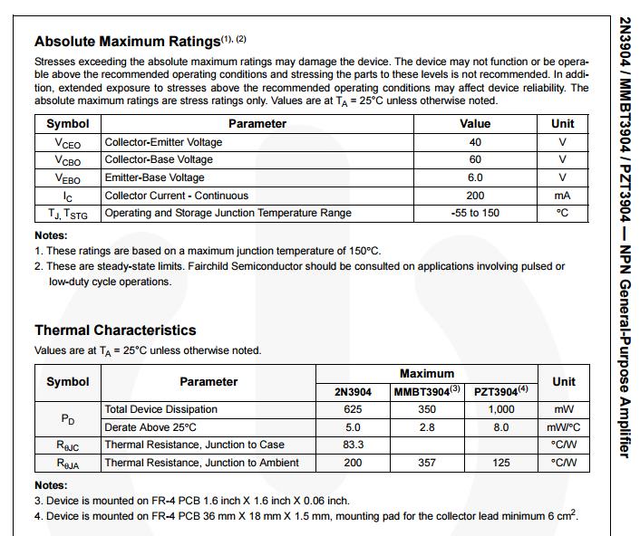
1 Laboratory 7 (drawn from lab text by Alciatore) Transistor and Photoelectric Circuits Required Components: 1x 330 resistor 2x 1 k resistors 1x 10k resistor 1x 2N3904 small signal transistor 1x TIP31C power transistor 1x 1N4004 small-signal diode 1 Radio Shack 1.5-3V DC motor (RS part number: ) 1x LED 1x photodiode/phototransistor pair (Newark part# 95B4823) or infrared diode/detector pair Objectives In this laboratory, you will study bipolar junction transistors (BJTs) and common photoelectric components. You will learn how to use light-emitting diodes (LEDs) as indicators, switch an inductive load with a power BJT, and use LED and phototransistor pairs as photo-interrupters. You will also learn how to bias a transistor and how to provide flyback protection with a diode. Introduction The following two pages provide information from the 2N3904 transistor data sheet. Data sheets provide pin-out information, where each pin is labeled with a function name and, if appropriate, a number. A data sheet also provides detailed electrical specifications that can help you properly design a circuit using the component. Figure 1 illustrates the nomenclature used to describe the behavior of an npn bipolar transistor. It is a three terminal device consisting of the base, collector, and emitter. The transistor acts like a current valve by using the voltage bias across the base and emitter (V BE ) to control the flow of current in the collector-emitter circuit (I c ). The circuit connected to the collector and emitter along with the bias voltage dictate how much current flows. 1
2 2
3 3
4 Figure 1: 1 npn bipolar transistor symbol and nomenclature. Here are some general relationships between the variables shown in Figure 1: V BE = V B V E (1) V CE = V C V E (2) I E = I B + I C (3) Also, generally, V C > V E (4) When the transistor is in saturation (i.e., fully ON), V BE 0.6V to 0.7V, V CE 0.2V, and I C I B (5) and when the transistor is in its cutoff state, V BE < 0.6V and I C = I B = I E = 0 (6) In the cutoff state, the transistor does not conduct current. 4
 the current I D based on the recorded voltages.")
5 Laboratory Procedure / Summary Sheet Names: 1. Build the simple LED indicator circuit shown below (without the 2nd resistor). See Section in textbook to identify the LED polarity. Gradually increase V in from 0 V to 5 V and record V in and measure V D when you consider the LED to be on. Also calculate (don't measure) the current I D based on the recorded voltages. V in = V D = I D = Figure 2 LED circuit. 2. Add the second resistor in parallel and repeat the same experiment looking for the V in where you consider the LED to be on. V in = V D = I D = Explain what happens and why. 5

6 3. Build a simple transistor switch (See figure below) using a 2N3904 small signal transistor and a base resistor (R B ) of 1 k. Use one channel of the DC power supply with a voltage meter to supply V in. Use another channel of the DC power supply for V 2 = 10V. Figure 3 Transistor switch circuit. Label the pins of the transistor in Fig. 3. Now use the 2N3904 datasheet provided to help you draw and label the pins on Fig. 4 and to record the following values: I C(max) = V CE(max) V BE(sat) = Figure 4 2N3904 pin-out. Vary V in as indicated in the table below and record the associated values for V BE and V CE. Use R B = 1 k for the base resistor. 6
7 V in V BE V CE Graph your data and describe your conclusions about when saturation occurs for the transistor. Change the base resistor (R B ) to 10 k and repeat the measurements. V in V BE V CE Graph your data and explain what the effect of a larger base resistor is? Why is this so? 7


8 4. Build the circuit shown in Figure 5 with a TIP31C transistor (note the pinout shown in the right side of the diagram below) and a 1.5V-3V DC motor. The TIP31C transistor is required to provide adequate current to the motor. Be sure to use the flyback diode as shown. This diode provides protection to the transistor when control signal V jn is turned off. Flyback diodes are recommended when switching inductive loads such as motors and solenoids. The 1N4004 diode is well suited to this motor" since the motor current is well within the surge current capacity of the diode. Figure 5 Motor and flyback diode. 8
9 Gradually increase V in from 0 V to 10 V and describe what happens. Apply a 5V pp, 2.5V DC offset (0 to 5V) square wave input to V in. Start with a low frequency (e.g., 1 Hz) and then try some higher frequencies, increasing the frequency in 1 Hz increments up to 20 Hz and then 10 Hz increments up to 100 Hz. Describe what happens. Explain how the flyback diode works. 9

10 5. Examine the photo-interrupter and look at its specifications. Build the circuit shown in Figure 6, using the resistors indicated. Note that a single 5V source can be used to provide both voltage signals, and the ground for the input and output circuits must be connected to be common. Figure 6 Photo-interrupter, the part number in the schematic is meaningless. Measure the output voltage (V out ) with and without the beam interrupted (e.g., with a thick sheet of paper or a plastic card). What conditions (interrupted or not) correspond to the high and low states of the output? Explain why each condition results in the respective state. Why are the resistors required? 10
Laboratory 5. Transistor and Photoelectric Circuits
 Laboratory 5 Transistor and Photoelectric Circuits Required Components: 1 330 resistor 2 1 k resistors 1 10k resistor 1 2N3904 small signal transistor 1 TIP31C power transistor 1 1N4001 power diode 1 Radio
EXPERIMENT 5 CURRENT AND VOLTAGE CHARACTERISTICS OF BJT
 EXPERIMENT 5 CURRENT AND VOLTAGE CHARACTERISTICS OF BJT 1. OBJECTIVES 1.1 To practice how to test NPN and PNP transistors using multimeter. 1.2 To demonstrate the relationship between collector current
Transistor Characteristics
 Transistor Characteristics Topics covered in this presentation: Transistor Construction Transistor Operation Transistor Characteristics 1 of 15 The Transistor The transistor is a semiconductor device that
ECE Solution to Homework #4
 ECE 3 Solution to Homework #4 Transistor Theory Transistor Switch Transistor Theory 1) Assume a transistor has the following V/I characteristics 1a) Label the regions corresponding to off / active / saturated
Başkent University Department of Electrical and Electronics Engineering EEM 214 Electronics I Experiment 8. Bipolar Junction Transistor
 Başkent University Department of Electrical and Electronics Engineering EEM 214 Electronics I Experiment 8 Bipolar Junction Transistor Aim: The aim of this experiment is to investigate the DC behavior
EXPERIMENT 6 REPORT Bipolar Junction Transistor (BJT) Characteristics
 Characteristics") Name & Surname: ID: Date: EXPERIMENT 6 REPORT Bipolar Junction Transistor (BJT) Characteristics Objectives: 1. To determine transistor type (npn, pnp),terminals, and material using a DMM 2. To graph the
Name & Surname: ID: Date: EXPERIMENT 6 REPORT Bipolar Junction Transistor (BJT) Characteristics Objectives: 1. To determine transistor type (npn, pnp),terminals, and material using a DMM 2. To graph the
Lecture 12. Bipolar Junction Transistor (BJT) BJT 1-1
 BJT 1-1") Lecture 12 Bipolar Junction Transistor (BJT) BJT 1-1 Course Info Lecture hours: 4 Two Lectures weekly (Saturdays and Wednesdays) Location: K2 Time: 1:40 pm Tutorial hours: 2 One tutorial class every week
Lecture 12 Bipolar Junction Transistor (BJT) BJT 1-1 Course Info Lecture hours: 4 Two Lectures weekly (Saturdays and Wednesdays) Location: K2 Time: 1:40 pm Tutorial hours: 2 One tutorial class every week
Introduction PNP C NPN C
 Introduction JT Transistors: A JT (or any transistor) can be used either as a switch with positions of on or off, or an amplifier that controls its output at all levels in between the extreme on or off
Transistors and Applications
 Chapter 17 Transistors and Applications DC Operation of Bipolar Junction Transistors (BJTs) The bipolar junction transistor (BJT) is constructed with three doped semiconductor regions separated by two
University of Utah Electrical & Computer Engineering Department ECE 2100 Experiment No. 7 Transistor Introduction (BJT)
") University of Utah Electrical & Computer Engineering Department ECE 2100 Experiment No. 7 Transistor Introduction (BJT) Minimum required points = 38 Grade base, 100% = 57 points Recommend parts = 57 points
University of Utah Electrical & Computer Engineering Department ECE 2100 Experiment No. 7 Transistor Introduction (BJT) Minimum required points = 38 Grade base, 100% = 57 points Recommend parts = 57 points
EXPERIMENT 12: SIMULATION STUDY OF DIFFERENT BIASING CIRCUITS USING NPN BJT
 EXPERIMENT 12: SIMULATION STUDY OF DIFFERENT BIASING CIRCUITS USING NPN BJT AIM: 1) To study different BJT DC biasing circuits 2) To design voltage divider bias circuit using NPN BJT SOFTWARE TOOL: PC
Lab no. 4 Bipolar Transistor (NPN and PNP)
") Lab no. 4 Bipolar Transistor (NPN and PNP) Transistors are semiconductor devices that enable to control the flow of large current by much smaller current. Bipolar transistor consists of three areas of
Lab no. 4 Bipolar Transistor (NPN and PNP) Transistors are semiconductor devices that enable to control the flow of large current by much smaller current. Bipolar transistor consists of three areas of
Chapter 3-2 Semiconductor devices Transistors and Amplifiers-BJT Department of Mechanical Engineering
 MEMS1082 Chapter 3-2 Semiconductor devices Transistors and Amplifiers-BJT Bipolar Transistor Construction npn BJT Transistor Structure npn BJT I = I + E C I B V V BE CE = V = V B C V V E E Base-to-emitter
Bipolar Junction Transistors (BJTs)
") C H A P T E R 6 Bipolar Junction Transistors (BJTs) Figure 6.1 A simplified structure of the npn transistor and pnp transistor. Table 6.1: BJT modes of Operation Mode Cutoff Active Saturation EBJ Reverse
C H A P T E R 6 Bipolar Junction Transistors (BJTs) Figure 6.1 A simplified structure of the npn transistor and pnp transistor. Table 6.1: BJT modes of Operation Mode Cutoff Active Saturation EBJ Reverse
Experiment No. 9 DESIGN AND CHARACTERISTICS OF COMMON BASE AND COMMON COLLECTOR AMPLIFIERS
 Experiment No. 9 DESIGN AND CHARACTERISTICS OF COMMON BASE AND COMMON COLLECTOR AMPLIFIERS 1. Objective: The objective of this experiment is to explore the basic applications of the bipolar junction transistor
University of North Carolina, Charlotte Department of Electrical and Computer Engineering ECGR 3157 EE Design II Fall 2009
 University of North Carolina, Charlotte Department of Electrical and Computer Engineering ECGR 3157 EE Design II Fall 2009 Lab 1 Power Amplifier Circuits Issued August 25, 2009 Due: September 11, 2009
ES 330 Electronics II Homework # 2 (Fall 2016 Due Wednesday, September 7, 2016)
") Page1 Name ES 330 Electronics II Homework # 2 (Fall 2016 Due Wednesday, September 7, 2016) Problem 1 (15 points) You are given an NMOS amplifier with drain load resistor R D = 20 k. The DC voltage (V RD
Page1 Name ES 330 Electronics II Homework # 2 (Fall 2016 Due Wednesday, September 7, 2016) Problem 1 (15 points) You are given an NMOS amplifier with drain load resistor R D = 20 k. The DC voltage (V RD
Electronics EECE2412 Spring 2017 Exam #2
 Electronics EECE2412 Spring 2017 Exam #2 Prof. Charles A. DiMarzio Department of Electrical and Computer Engineering Northeastern University 30 March 2017 File:12198/exams/exam2 Name: : General Rules:
LAB PROJECT 2. Lab Exercise
 LAB PROJECT 2 Objective Investigate photoresistors, infrared light emitting diodes (IRLED), phototransistors, and fiber optic cable. Type a semi-formal lab report as described in the lab manual. Use tables
output passes full first (positive) hump and 1/2-scale second hump
 hump and 1/2-scale second hump") 3. For V i > 0, V o 0. For V i < 0, V o V i. The resulting waveform consists only of the negative "humps" of the original cosine wave. Each hump has a duration of 0.5s there is a 0.5s gap between each
3. For V i > 0, V o 0. For V i < 0, V o V i. The resulting waveform consists only of the negative "humps" of the original cosine wave. Each hump has a duration of 0.5s there is a 0.5s gap between each
ECEN 325 Lab 7: Characterization and DC Biasing of the BJT
 ECEN 325 Lab 7: Characterization and DC Biasing of the BJT 1 Objectives The purpose of this lab is to characterize NPN and PNP bipolar junction transistors (BJT), and to analyze and design DC biasing circuits
Laboratory Four - Bipolar Junction Transistor (BJT)
") M/IS 3512 ioelectronics Laboratory Four - ipolar Junction Transistor (JT) Learning Objectives: Know how to differentiate between PNP & NPN JT transistors using a multimeter. e familiar with the operation
M/IS 3512 ioelectronics Laboratory Four - ipolar Junction Transistor (JT) Learning Objectives: Know how to differentiate between PNP & NPN JT transistors using a multimeter. e familiar with the operation
The collector terminal is common to the input and output signals and is connected to the dc power supply. Common Collector Circuit
 Common Collector Circuit When you have completed this exercise, you will be able to determine the dc operating conditions of a common collector (CC) transistor circuit by using a typical CC circuit. You
BJT Characteristics & Common Emitter Transistor Amplifier
 LAB #07 Objectives 1. To graph the collector characteristics of a transistor. 2. To measure AC and DC voltages in a common-emitter amplifier. Theory BJT A bipolar (junction) transistor (BJT) is a three-terminal
7. Bipolar Junction Transistor
 41 7. Bipolar Junction Transistor 7.1. Objectives - To experimentally examine the principles of operation of bipolar junction transistor (BJT); - To measure basic characteristics of n-p-n silicon transistor
ET215 Devices I Unit 4A
 ITT Technical Institute ET215 Devices I Unit 4A Chapter 3, Section 3.1-3.2 This unit is divided into two parts; Unit 4A and Unit 4B Chapter 3 Section 3.1 Structure of Bipolar Junction Transistors The basic
Lab 3: BJT Digital Switch
 Lab 3: BJT Digital Switch Objectives The purpose of this lab is to acquaint you with the basic operation of bipolar junction transistor (BJT) and to demonstrate its functionality in digital switching circuits.
C H A P T E R 6 Bipolar Junction Transistors (BJTs)
") C H A P T E R 6 Bipolar Junction Transistors (BJTs) Figure 6.1 A simplified structure of the npn transistor and pnp transistor. Table 6.1: BJT modes of Operation Mode EBJ CBJ Cutoff Reverse Reverse Active
C H A P T E R 6 Bipolar Junction Transistors (BJTs) Figure 6.1 A simplified structure of the npn transistor and pnp transistor. Table 6.1: BJT modes of Operation Mode EBJ CBJ Cutoff Reverse Reverse Active
4 Transistors. 4.1 IV Relations
 4 Transistors Due date: Sunday, September 19 (midnight) Reading (Bipolar transistors): HH sections 2.01-2.07, (pgs. 62 77) Reading (Field effect transistors) : HH sections 3.01-3.03, 3.11-3.12 (pgs. 113
Electronic Component Applications
 Western Technical College 10660124 Electronic Component Applications Course Outcome Summary Course Information Description Career Cluster Instructional Level Total Credits 2.00 Total Hours 60.00 Solid
I C I E =I B = I C 1 V BE 0.7 V
 Guide to NPN Amplifier Analysis Jason Woytowich 1. Transistor characteristics A BJT has three operating modes cutoff, active, and saturation. For applications, like amplifiers, where linear characteristics
Laboratory 6 Diodes and Transistors
 Laboratory 6 page 1 of 6 Laboratory 6 Diodes and Transistors Introduction In this lab, you will build and test circuits using diodes and transistors. You will use a number of different types of diodes,
Experiment 8: Semiconductor Devices
 Name/NetID: Experiment 8: Semiconductor Devices Laboratory Outline In today s experiment you will be learning to use the basic building blocks that drove the ability to miniaturize circuits to the point
Lecture 24: Bipolar Junction Transistors (1) Bipolar Junction Structure, Operating Regions, Biasing
 Bipolar Junction Structure, Operating Regions, Biasing") Lecture 24: Bipolar Junction Transistors (1) Bipolar Junction Structure, Operating Regions, Biasing BJT Structure the BJT is formed by doping three semiconductor regions (emitter, base, and collector)
Lecture 24: Bipolar Junction Transistors (1) Bipolar Junction Structure, Operating Regions, Biasing BJT Structure the BJT is formed by doping three semiconductor regions (emitter, base, and collector)
SEMICONDUCTOR ELECTRONICS: MATERIALS, DEVICES AND SIMPLE CIRCUITS. Class XII : PHYSICS WORKSHEET
 SEMICONDUCT ELECTRONICS: MATERIALS, DEVICES AND SIMPLE CIRCUITS Class XII : PHYSICS WKSHEET 1. How is a n-p-n transistor represented symbolically? (1) 2. How does conductivity of a semiconductor change
Dr. Charles Kim ELECTRONICS I. Lab 5 Bipolar Junction Transistor (BJT) I TRADITIONAL LAB
 I TRADITIONAL LAB") ELECTRONICS I Lab 5 Bipolar Junction Transistor (BJT) I TRADITIONAL LAB MOBILE STUDIO LAB Before We Start A transistor is a 3-terminal device available in two configurations, NPN and PNP. The transistor
ELECTRONICS I Lab 5 Bipolar Junction Transistor (BJT) I TRADITIONAL LAB MOBILE STUDIO LAB Before We Start A transistor is a 3-terminal device available in two configurations, NPN and PNP. The transistor
Experiment 9 Bipolar Junction Transistor Characteristics
 Experiment 9 Bipolar Junction Transistor Characteristics W.T. Yeung, W.Y. Leung, and R.T. Howe UC Berkeley EE 105 Fall 2005 1.0 Objective In this lab, you will determine the I C - V CE characteristics
University of Michigan EECS 311: Electronic Circuits Fall Quiz 2 11/3/2008
 University of Michigan EECS 311: Electronic Circuits Fall 2008 Quiz 2 11/3/2008 NAME: Honor Code: I have neither given nor received unauthorized aid on this examination, nor have I concealed any violations
Chapter 3: Bipolar Junction Transistors
 Chapter 3: Bipolar Junction Transistors Transistor Construction There are two types of transistors: pnp npn pnp The terminals are labeled: E - Emitter B - Base C - Collector npn 2 Transistor Operation
KOM2751 Analog Electronics :: Dr. Muharrem Mercimek :: YTU - Control and Automation Dept. 1 2 (CONT D - II) DIODE APPLICATIONS
 DIODE APPLICATIONS") KOM2751 Analog Electronics :: Dr. Muharrem Mercimek :: YTU - Control and Automation Dept. 1 2 (CONT D - II) DIODE APPLICATIONS Most of the content is from the textbook: Electronic devices and circuit theory,
KOM2751 Analog Electronics :: Dr. Muharrem Mercimek :: YTU - Control and Automation Dept. 1 2 (CONT D - II) DIODE APPLICATIONS Most of the content is from the textbook: Electronic devices and circuit theory,
STATIC CHARACTERISTICS OF TRANSISTOR
 STAT CHARACTERISTS OF TRANSISTOR OBJECTIVE The purpose of the experiment is to study the characteristics of bipolar transistor in common emitter (CE) configuration. From the characteristic curve it is
SCHEMATIC OF GRAYMARK 808 POWERED BREADBOARD
 SCHEMATIC OF GRAYMARK 808 POWERED BREADBOARD 1a white SW1 white 2a TP1 blue TP2 black blue TP3 TP4 yellow TP5 yellow TP6 4 3 8 7 + D1 D2 D5 D6 C1 R1 TP8 Q1 R3 TP12 2 TP18 U2-0-15V C8 9 C2 + TP15 C5 R12
A 3-STAGE 5W AUDIO AMPLIFIER
 ECE 2201 PRELAB 7x BJT APPLICATIONS A 3-STAGE 5W AUDIO AMPLIFIER UTILIZING NEGATIVE FEEDBACK INTRODUCTION Figure P7-1 shows a simplified schematic of a 3-stage audio amplifier utilizing three BJT amplifier
E B C. Two-Terminal Behavior (For testing only!) TO-92 Case Circuit Symbol
 TO-92 Case Circuit Symbol") Physics 310 Lab 5 Transistors Equipment: Little silver power-supply, little black multimeter, Decade Resistor Box, 1k,, 470, LED, 10k, pushbutton switch, 270, 2.7k, function generator, o scope, two 5.1k
Physics 310 Lab 5 Transistors Equipment: Little silver power-supply, little black multimeter, Decade Resistor Box, 1k,, 470, LED, 10k, pushbutton switch, 270, 2.7k, function generator, o scope, two 5.1k
Mechatronics and Measurement. Lecturer:Dung-An Wang Lecture 2
 Mechatronics and Measurement Lecturer:Dung-An Wang Lecture 2 Lecture outline Reading:Ch3 of text Today s lecture Semiconductor 2 Diode 3 4 Zener diode Voltage-regulator diodes. This family of diodes exhibits
ELEC 2210 EXPERIMENT 7 The Bipolar Junction Transistor (BJT)
") ELEC 2210 EXPERIMENT 7 The Bipolar Junction Transistor (BJT) Objectives: The experiments in this laboratory exercise will provide an introduction to the BJT. You will use the Bit Bucket breadboarding system
ELEC 2210 EXPERIMENT 7 The Bipolar Junction Transistor (BJT) Objectives: The experiments in this laboratory exercise will provide an introduction to the BJT. You will use the Bit Bucket breadboarding system
Laboratory #5 BJT Basics and MOSFET Basics
 Laboratory #5 BJT Basics and MOSFET Basics I. Objectives 1. Understand the physical structure of BJTs and MOSFETs. 2. Learn to measure I-V characteristics of BJTs and MOSFETs. II. Components and Instruments
EE320L Electronics I. Laboratory. Laboratory Exercise #6. Current-Voltage Characteristics of Electronic Devices. Angsuman Roy
 EE320L Electronics I Laboratory Laboratory Exercise #6 Current-Voltage Characteristics of Electronic Devices By Angsuman Roy Department of Electrical and Computer Engineering University of Nevada, Las
EXPERIMENT 10: SINGLE-TRANSISTOR AMPLIFIERS 11/11/10
 EXPERIMENT 10: SINGLE-TRANSISTOR AMPLIFIERS 11/11/10 In this experiment we will measure the characteristics of the standard common emitter amplifier. We will use the 2N3904 npn transistor. If you have
CHAPTER 3: BIPOLAR JUNCION TRANSISTOR DR. PHẠM NGUYỄN THANH LOAN
 CHAPTER 3: BIPOLAR JUNCION TRANSISTOR DR. PHẠM NGUYỄN THANH LOAN Hanoi, 9/24/2012 Contents 2 Structure and operation of BJT Different configurations of BJT Characteristic curves DC biasing method and analysis
b b Fig. 1 Transistor symbols
 TRANSISTORS Transistors have three terminals which are referred to as emitter (e), base (b) and collector (c). Fig 1 shows the symbols used for the two types of transistors in common use. c c b b e e npn
Electromagnetic spectrum
 Slide 1 Electromagnetic spectrum insert wavelengths of blue to red. 6.071 Optoelectronics 1 Slide 2 Electromagnetic spectrum E = hν = kt e E - Energy k - Plank s constant ν - frequency k - Boltzman s constant
Diode and Bipolar Transistor Circuits
 Diode and Bipolar Transistor Circuits 2 2.1 A Brief Review of Semiconductors Semiconductors are crystalline structures in which each atom shares its valance electrons with the neighboring atoms. The simple
PHY405F 2009 EXPERIMENT 6 SIMPLE TRANSISTOR CIRCUITS
 PHY405F 2009 EXPERIMENT 6 SIMPLE TRANSISTOR CIRCUITS Due Date (NOTE CHANGE): Thursday, Nov 12 th @ 5 pm; Late penalty in effect! Most active electronic devices are based on the transistor as the fundamental
Page 1 of 7. Power_AmpFal17 11/7/ :14
 ECE 3274 Power Amplifier Project (Push Pull) Richard Cooper 1. Objective This project will introduce two common power amplifier topologies, and also illustrate the difference between a Class-B and a Class-AB
DC Bias. Graphical Analysis. Script
 Course: B.Sc. Applied Physical Science (Computer Science) Year & Sem.: Ist Year, Sem - IInd Subject: Electronics Paper No.: V Paper Title: Analog Circuits Lecture No.: 3 Lecture Title: Analog Circuits
o Semiconductor Diode Symbol: The cathode contains the N-type material and the anode contains the P-type material.
 Cornerstone Electronics Technology and Robotics I Week 16 Diodes and Transistor Switches Administration: o Prayer o Turn in quiz Review: o Design and wire a voltage divider that divides your +9 V voltage
Chapter 3. Bipolar Junction Transistors
 Chapter 3. Bipolar Junction Transistors Outline: Fundamental of Transistor Common-Base Configuration Common-Emitter Configuration Common-Collector Configuration Introduction The transistor is a three-layer
Current Mirrors. Basic BJT Current Mirror. Current mirrors are basic building blocks of analog design. Figure shows the basic NPN current mirror.
 Current Mirrors Basic BJT Current Mirror Current mirrors are basic building blocks of analog design. Figure shows the basic NPN current mirror. For its analysis, we assume identical transistors and neglect
2. SINGLE STAGE BIPOLAR JUNCTION TRANSISTOR (BJT) AMPLIFIERS
 AMPLIFIERS") 2. SINGLE STAGE BIPOLAR JUNCTION TRANSISTOR (BJT) AMPLIFIERS I. Objectives and Contents The goal of this experiment is to become familiar with BJT as an amplifier and to evaluate the basic configurations
2. SINGLE STAGE BIPOLAR JUNCTION TRANSISTOR (BJT) AMPLIFIERS I. Objectives and Contents The goal of this experiment is to become familiar with BJT as an amplifier and to evaluate the basic configurations
Chapter 6: Transistors and Gain
 I. Introduction Chapter 6: Transistors and Gain This week we introduce the transistor. Transistors are three-terminal devices that can amplify a signal and increase the signal s power. The price is that
(a) BJT-OPERATING MODES & CONFIGURATIONS
 BJT-OPERATING MODES & CONFIGURATIONS") (a) BJT-OPERATING MODES & CONFIGURATIONS 1. The leakage current I CBO flows in (a) The emitter, base and collector leads (b) The emitter and base leads. (c) The emitter and collector leads. (d) The base
(a) BJT-OPERATING MODES & CONFIGURATIONS 1. The leakage current I CBO flows in (a) The emitter, base and collector leads (b) The emitter and base leads. (c) The emitter and collector leads. (d) The base
Laboratory 4: Biasing of Bipolar Transistors Laboratory Exercises
 Laboratory 4: Biasing of Bipolar Transistors Laboratory Exercises INTRODUCTION Objectives In this lab, we will design and build three different bias circuits for BJT s (Bipolar Junction Transistors). In
5.1 BJT Device Structure and Physical Operation
 11/28/2004 section 5_1 BJT Device Structure and Physical Operation blank 1/2 5.1 BJT Device Structure and Physical Operation Reading Assignment: pp. 377-392 Another kind of transistor is the Bipolar Junction
ECE 334: Electronic Circuits Lecture 2: BJT Large Signal Model
 Faculty of Engineering ECE 334: Electronic Circuits Lecture 2: BJT Large Signal Model Agenda I & V Notations BJT Devices & Symbols BJT Large Signal Model 2 I, V Notations (1) It is critical to understand
ELEG 309 Laboratory 4
 ELEG 309 Laboratory 4 BIPOLAR-TRANSISTOR BASICS April 17, 2000 1 Objectives Our overall objective is to familiarize you with the basic properties of Bipolar Junction Transistors (BJTs) in preparation for
EXPERIMENT #3 TRANSISTOR BIASING
 EXPERIMENT #3 TRANSISTOR BIASING Bias (operating point) for a transistor is established by specifying the quiescent (D.C., no signal) values of collector-emitter voltage V CEQ and collector current I CQ.
ITT Technical Institute. ET215 Devices 1. Unit 6 Chapter 3, Sections
 ITT Technical Institute ET215 Devices 1 Unit 6 Chapter 3, Sections 3.7-3.9 Chapter 3 Section 3.7 The Bipolar Transistor as a Switch Objectives: Explain how a transistor can be used as a switch 1. Compute
Chapter Two "Bipolar Transistor Circuits"
 Chapter Two "Bipolar Transistor Circuits" 1.TRANSISTOR CONSTRUCTION:- The transistor is a three-layer semiconductor device consisting of either two n- and one p-type layers of material or two p- and one
ชาว ศวกรรมคอมพ วเตอร คณะว ศวกรรมศาสตร มหาว ทยาล ยเทคโนโลย ราชมงคลพระนคร
 EN2042102 วงจรไฟฟ าและอ เล กทรอน กส Circuits and Electronics บทท 7 ทรานซ สเตอร Bipolar Junction Transistor สาขาว ชาว ศวกรรมคอมพ วเตอร คณะว ศวกรรมศาสตร มหาว ทยาล ยเทคโนโลย ราชมงคลพระนคร Objectives Describe
The first transistor. (Courtesy Bell Telephone Laboratories.)
") Fig. 3.1 The first transistor. (Courtesy Bell Telephone Laboratories.) Fig. 3.2 Types of transistors: (a) pnp; (b) npn. : (a) pnp; : (b) npn Fig. 3.3 Forward-biased junction of a pnp transistor. Fig. 3.4
Fig. 3.1 The first transistor. (Courtesy Bell Telephone Laboratories.) Fig. 3.2 Types of transistors: (a) pnp; (b) npn. : (a) pnp; : (b) npn Fig. 3.3 Forward-biased junction of a pnp transistor. Fig. 3.4
Laboratory exercise: the Bipolar Transistor
 Laboratory exercise: the Bipolar Transistor Semiconductor Physics 2014 Lab meeting point k-space at Solid State Physics This exercise consists of two experimental parts and one simulation part. In the
Lecture 3: Transistors
 Lecture 3: Transistors Now that we know about diodes, let s put two of them together, as follows: collector base emitter n p n moderately doped lightly doped, and very thin heavily doped At first glance,
Analog Circuits Laboratory EXPERIMENT 3: BJT CURRENT SOURCES
 EE171L rev2 1 University of California, Santa Cruz Baskin School of Engineering Electrical Engineering Department Analog Circuits Laboratory EXPERIMENT 3: BJT CURRENT SOURCES 1. DESCRIPTION AND OBJECTIVES
EE 330 Laboratory 8 Discrete Semiconductor Amplifiers
 EE 330 Laboratory 8 Discrete Semiconductor Amplifiers Fall 2018 Contents Objective:...2 Discussion:...2 Components Needed:...2 Part 1 Voltage Controlled Amplifier...2 Part 2 A Nonlinear Application...3
INSTRUCTOR S COURSE REQUIREMENTS
 INSTRUCTOR S COURSE REQUIREMENTS PO Box 1189 1042 W. Hamlet Avenue Hamlet, NC 28345 (910) 410-1700 www.richmondcc.edu COURSE: ELN 131 Analog Electronics I SEMESTER & YEAR: SPRING 2015 INSTRUCTOR S NAME
Chapter 3 Bipolar Junction Transistors (BJT)
") Chapter 3 Bipolar Junction Transistors (BJT) Transistors In analog circuits, transistors are used in amplifiers and linear regulated power supplies. In digital circuits they function as electrical switches,
Chapter 3 Bipolar Junction Transistors (BJT) Transistors In analog circuits, transistors are used in amplifiers and linear regulated power supplies. In digital circuits they function as electrical switches,
Lecture (06) Bipolar Junction Transistor
 Bipolar Junction Transistor") Lecture (06) Bipolar Junction Transistor By: Dr. Ahmed lshafee ١ Agenda BJT structure BJT operation BJT characteristics ٢ BJT structure The BJT is constructed with three doped semiconductor regions One
Lecture (06) Bipolar Junction Transistor By: Dr. Ahmed lshafee ١ Agenda BJT structure BJT operation BJT characteristics ٢ BJT structure The BJT is constructed with three doped semiconductor regions One
Physics 481 Experiment 3
 Physics 481 Experiment 3 LAST Name (print) FIRST Name (print) TRANSISTORS (BJT & FET) npn BJT n-channel MOSFET 1 Experiment 3 Transistors: BJT & FET In this experiment transistor properties and transistor
Lecture #3 ( 2 weeks) Transistors
 Transistors") Spring 2015 Benha University Faculty of Engineering at Shoubra ECE-291 Electronic Engineering Lecture #3 ( 2 weeks) Transistors Instructor: Dr. Ahmad El-Banna 1 Agenda BJT Structure Basic Operation Transistor
Spring 2015 Benha University Faculty of Engineering at Shoubra ECE-291 Electronic Engineering Lecture #3 ( 2 weeks) Transistors Instructor: Dr. Ahmad El-Banna 1 Agenda BJT Structure Basic Operation Transistor
Figure 1. Block diagram of system incorporating power amplification.
 It is often necessary use a circuit which has very low power capabilities to drive a system which has relatively high power requirements. This is typically accomplished by using an amplifier as an intermediate
Introduction to Electronics. Dr. Lynn Fuller
 ROCHESTER INSTITUTE OF TECHNOLOGY MICROELECTRONIC ENGINEERING Introduction to Electronics Dr. Lynn Fuller Webpage: http://www.rit.edu/~lffeee 82 Lomb Memorial Drive Rochester, NY 14623-5604 Tel (585) 475-2035
Phy 335, Unit 4 Transistors and transistor circuits (part one)
") Mini-lecture topics (multiple lectures): Phy 335, Unit 4 Transistors and transistor circuits (part one) p-n junctions re-visited How does a bipolar transistor works; analogy with a valve Basic circuit
Mini-lecture topics (multiple lectures): Phy 335, Unit 4 Transistors and transistor circuits (part one) p-n junctions re-visited How does a bipolar transistor works; analogy with a valve Basic circuit
Bipolar Junction Transistors
 Bipolar Junction Transistors Invented in 1948 at Bell Telephone laboratories Bipolar junction transistor (BJT) - one of the major three terminal devices Three terminal devices more useful than two terminal
Real Analog - Circuits 1 Chapter 1: Lab Projects
 Real Analog Circuits 1 Chapter 1: Lab Projects 1.4.1: DusktoDawn Light Overview: In this lab, we will create our first circuit which appears to do something which is readily perceivable without instrumentation.
Lecture #3 BJT Transistors & DC Biasing
 November 2014 Ahmad El-Banna Integrated Technical Education Cluster At AlAmeeria J-601-1448 Electronic Principals Lecture #3 BJT Transistors & DC Biasing Instructor: Dr. Ahmad El-Banna Agenda Transistor
Concepts to be Covered
 Introductory Medical Device Prototyping Analog Circuits Part 2 Semiconductors, http://saliterman.umn.edu/ Department of Biomedical Engineering, University of Minnesota Concepts to be Covered Semiconductors
Revised: Summer 2010
 EE 2274 PRE-LAB EXPERIMENT 5 DIODE OR GATE & CLIPPING CIRCUIT COMPLETE PRIOR TO COMING TO LAB Part I: 1. Design a diode, Figure 1 OR gate in which the maximum input current,, Iin is less than 5mA. Show
Chapters 11 & 12 Electronic Controls & Automation
 Chapters 11 & 12 Electronic Controls & Automation Use the Textbook Pages 255 297 to help answer the questions Why You Learn So Well in Tech & Engineering Classes 1. All control systems have and devices.
FET, BJT, OpAmp Guide
 FET, BJT, OpAmp Guide Alexandr Newberry UCSD PHYS 120 June 2018 1 FETs 1.1 What is a Field Effect Transistor? Figure 1: FET with all relevant values labelled. FET stands for Field Effect Transistor, it
The Semiconductor Diode
 Physics Topics The Semiconductor Diode If necessary, review the following topics and relevant textbook sections from Neamen Semiconductor Physics and Devices, 4th Ed. Section 8.1.5, especially equation
Lecture (09) Bipolar Junction Transistor 3
 Bipolar Junction Transistor 3") Lecture (09) Bipolar Junction Transistor 3 By: Dr. Ahmed ElShafee ١ I THE BJT AS AN AMPLIFIER Amplification is the process of linearly increasing the amplitude of an electrical signal and is one of the
Lecture (09) Bipolar Junction Transistor 3 By: Dr. Ahmed ElShafee ١ I THE BJT AS AN AMPLIFIER Amplification is the process of linearly increasing the amplitude of an electrical signal and is one of the
10 Semiconductors - Transistors
 10 Semiconductors - Transistors The transistor was invented in the late 1940s. Credit for its invention is given to three Bell Laboratories scientists, John Bardeen, Walter Brattain, and William Shockley.
Bipolar Junction Transistor (BJT)
") Bipolar Junction Transistor (BJT) - three terminal device - output port controlled by current flow into input port Structure - three layer sandwich of n-type and p-type material - npn and pnp transistors
Bipolar Junction Transistor (BJT) - three terminal device - output port controlled by current flow into input port Structure - three layer sandwich of n-type and p-type material - npn and pnp transistors
Transistor Biasing. DC Biasing of BJT. Transistor Biasing. Transistor Biasing 11/23/2018
 Transistor Biasing DC Biasing of BJT Satish Chandra Assistant Professor Department of Physics P P N College, Kanpur www.satish0402.weebly.com A transistors steady state of operation depends a great deal
Dr. Charles Kim ELECTRONICS I. Lab 6 Bipolar Junction Transistor (BJT) II TRADITIONAL LAB
 II TRADITIONAL LAB") ELECTRONICS I Lab 6 Bipolar Junction Transistor (BJT) II TRADITIONAL LAB MOBILE STUDIO LAB Before We Start As the title of this lab says, this lab is about designing a Common-Emitter Amplifier, and this
ELECTRONICS I Lab 6 Bipolar Junction Transistor (BJT) II TRADITIONAL LAB MOBILE STUDIO LAB Before We Start As the title of this lab says, this lab is about designing a Common-Emitter Amplifier, and this
.dc Vcc Ib 0 50uA 5uA
 EE 2274 BJT Biasing PreLab: 1. Common Emitter (CE) Transistor Characteristics curve Generate the characteristics curves for a 2N3904 in LTspice by plotting Ic by sweeping Vce over a set of Ib steps. Label
Experiment (1) Principles of Switching
 Principles of Switching") Experiment (1) Principles of Switching Introduction When you use microcontrollers, sometimes you need to control devices that requires more electrical current than a microcontroller can supply; for this,
Experiment (1) Principles of Switching Introduction When you use microcontrollers, sometimes you need to control devices that requires more electrical current than a microcontroller can supply; for this,
I1 19u 5V R11 1MEG IDC Q7 Q2N3904 Q2N3904. Figure 3.1 A scaled down 741 op amp used in this lab
 Lab 3: 74 Op amp Purpose: The purpose of this laboratory is to become familiar with a two stage operational amplifier (op amp). Students will analyze the circuit manually and compare the results with SPICE.
Lecture 9 Transistors
 Lecture 9 Transistors Physics Transistor/transistor logic CMOS logic CA 1947 http://www.extremetech.com/extreme/164301-graphenetransistors-based-on-negative-resistance-could-spell-theend-of-silicon-and-semiconductors