Radio Frequency Electronics
|
|
|
- Emily Patterson
- 5 years ago
- Views:
Transcription


1 Radio Frequency Electronics Preliminaries III Lee de Forest Born in Council Bluffs, Iowa in 1873 Had 180 patents Invented the vacuum tube that allows for building electronic amplifiers Vacuum tube started electronics age Patented Phonofilm, an improved method of adding a soundtrack to movies Transmitted first radio add Transmitted first radio report on Presidential election Supposedly said: I came, I saw, I invented it's that simple no need to sit and think it's all in your imagination. Image from Wikipedia 1


2 Litz Wire Due to the skin and proximity effects, current in ac circuits flows near the surface of the conductor. This increases the ac resistance of the conductor. In transformers and inductors the proximity effect ma dominate. To mitigate these effects, one can increase the surface area by bundling many small-diameter strands that are insulated from each other. Litz wire find application in high frequency inductors and transformers, inverters, communication equipment, ultrasonic equipment, sonar equipment, television and radio equipment and induction heating equipment. Litz is derived from the German word Litzendraht meaning woven wire. The weaving patterns are designed to ensure the current in is all strands are equal. Eight strands of insolated wire bundled together. Images from Wikipedia 2


3 Litz Wire In RF work, Litz wire is used up to 1-3 MHz or so. It is used for RFC, inductors, and ferrite antennas. 0.5 H Inductor from Digikey Catalog. SRF = 52 khz. Portable radios use litz wire for LW and MW antennas RFC from a vintage radio. The wire is almost certainly litz. 3


4 Litz Wire Applications Ferrite rod antenna with two windings. The main winding resonates will a tunic capacitor. Litz wire is used to reduce coils ac resistance. The main and coupled winding acts as a transformer an can improve impedance matching with the first RF stage. Ferrite rod antenna with litz wire windings for LW (< 300 khz) and MF (535 khz to 1705 khz) reception Image from Wikipedia 4
5 Inductor Quality Factor An ideal inductor has no resistance (or capacitance), only inductance. A metric for how good an actual inductor is, is the so-called quality factor. The quality factor is also used for capacitors and filters, and we will be using it extensively through the course. It is defined as peak enery stored per cycle 2 energy dissipated per cycle Assuming sin, the peak energy stored is 1 2 Energy dissipated/cycle is: peak enery stored per cycle 2 energy dissipated per cycle
6 Inductor Quality Factor peak enery stored per cycle 2 energy dissipated per cycle Note that Reactance Series Resistance This is also true for a capacitor with a series resistance: 1 Reactance Series Resistance 1 1 Thus, we can write X where s indicates a series connection One can show for the case where a resistor is in parallel with a reactance then inductor 1 capacitor 6
 is also specified. This is typically lower than the obtained from Why? 7")
7 Inductors Specifications Data sheets often assume the following model Simplified model at a specific frequency. (or is the component que s series For inductors that are used in signal processing (i.e., filters), the indcutor iductance and a number, the inductor, is normally specified along with the inductance. From this one can determine. For inductors is assumes to be unless otherwise noted. Often, (i.e., the resistance at dc) is also specified. This is typically lower than the obtained from Why? 7


8 Inductor Specifications Note that the manufacturer did not specify or SRF 10 mh adjustable inductor at the specified frequency 8
9 LR Series LR Parallel Transformation It is often convenient to work with a parallel network rather than a series network and there exists transformations between the two representations. Also since peak enery stored energy dissipated per cycle 1 1 it follows from conservation of energy that If the component is large then 1, so one can simplify as follows: 9
10 LR Series LR Parallel Transformation Where do such transformations come from? Below we derive the inverse of the series parallel Parallel network Series network For the real parts must be equal and the imaginary parts must be equal Equate real parts 1 1 where Equate imaginary parts
11 Example Example. Compute the of a 50 nh inductor with series resistance 10 Ω at 100 MHz. Transform the circuit to an equivalent parallel network. Solution. The of the inductor is Since is low, we will not use the approximation. Rather ,08.7 Ω nh 11

12 Capacitors = permittivity of free space F/m = relative permittivity Graphic from Wikipedia 12
13 Capacitor Assuming the capacitance is known, we use the following equations for circuit analysis. Time domain. Differential equation Energy (Joule) Frequency/phasor domain (steady state sinusoidal). Reactance (Ω) 90 Frequency/phasor domain (steady state sinusoidal). lags by 90 1 s-domain 1 Time constant for a single time constant circuit, reactive element 13


14 Capacitors Graphic from Wikipedia 14
15 Capacitor Models The Equivalent Series Resistance (ESR) is, strictly-speaking the equivalent series resistance at a specific frequency, but in practice people use the term as if it is frequency-independent 15
16 Capacitor Frequency Response Above ~ 20 MHz, this capacitor behaves as an inductor Self Resonance Frequency (SRF) 16


17 Decoupling Capacitors What is going on here and here? Question: Why place a 100 nf capacitor in parallel with a 100 F capacitor? Answer: The 100 F will begin to behave like an inductor as some frequency. At this frequency the 100 nf takes over and ensure low reactance. 17


18 Build a Good Capacitor One should carefully consider package sizes, since that determines inductance It is very common in RF and high-speed digital work to place a number of capacitors in parallel so that the composite capacitor has a low reactance where desired. Graphic from Planet Analog 18


19 De-queing 19
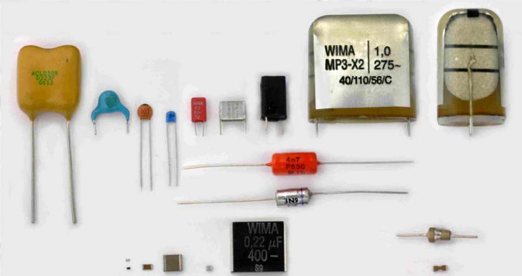
20 Ceramic Capacitor Construction Dipped ceramic capacitors are cut from large sheets of green ceramic material and fired. Electrodes are screen printed using silver, finely powdered glass, and a binder on both sides of the disk, then back to the oven. This evaporates the binder, and the melted glass binds the silver to the ceramic surface. Next, hairpin wires are clipped onto the capacitor and it is dipped in solder. These capacitors are inexpensive and available in values less that ~ 1 µf. These capacitors are inexpensive and available in values less that ~ 1 µf. 20
21 Monolithic/Multilayer Ceramic Capacitors A Surface Mount (SMT) MLC capacitor. The base ceramic material is mixed with a binder and fashioned into sheets. Electrodes are painted onto one side of the sheets using a paint that consists of a liquid binder with fine metal particles in suspension. The sheets are stacked on top of each other. The painted electrodes are arranged so that alternate electrodes exit from opposite ends. The laminated layers are then compressed and fired, which sinters them into one monolithic structure. The ends are terminated, often using silver. For leaded capacitors, wires are attached, and finally the capacitor is encapsulated in plastic and marked 21
22 Capacitor Quality Factor Recall the definition of the component peak enery stored per cycle 2 energy dissipated per cycle X s series p parallel 1 1 capacitor 22

23 RC Parallel Series RC Transformations Parallel network Series network For the real parts must be equal and the imaginary parts must be equal With the of the parallel network, the expressions become
24 Capacitor Terminology Power Factor (PF) and Dissipation Factor (DF) Real capacitors have both resistive and reactive components (see the model for the capacitor) Z ( j) R( ) jx ( ) PF power loss apparent power I I 2 2 R Z R Z cos DF power loss reactive power stored I I 2 2 R X R X cot tan DF is normally expressed as a percentage. For example, if the DF of a capacitor is 13%, then: tan

25 25
Radio Frequency Electronics
 Radio Frequency Electronics Preliminaries II Guglielmo Giovanni Maria Marconi Thought off by many people as the inventor of radio Pioneer in long-distance radio communications Shared Nobel Prize in 1909
CHAPTER 2. Basic Concepts, Three-Phase Review, and Per Unit
 CHAPTER 2 Basic Concepts, Three-Phase Review, and Per Unit 1 AC power versus DC power DC system: - Power delivered to the load does not fluctuate. - If the transmission line is long power is lost in the
Homework Assignment 03
 Question (75 points) Homework Assignment 03 Overview Tuned Radio Frequency (TRF) receivers are some of the simplest type of radio receivers. They consist of a parallel RLC bandpass filter with bandwidth
What is an Inductor? Token Electronics Industry Co., Ltd. Version: January 16, Web:
 Version: January 16, 2017 What is an Inductor? Web: www.token.com.tw Email: rfq@token.com.tw Token Electronics Industry Co., Ltd. Taiwan: No.137, Sec. 1, Zhongxing Rd., Wugu District, New Taipei City,
University of Jordan School of Engineering Electrical Engineering Department. EE 219 Electrical Circuits Lab
 University of Jordan School of Engineering Electrical Engineering Department EE 219 Electrical Circuits Lab EXPERIMENT 4 TRANSIENT ANALYSIS Prepared by: Dr. Mohammed Hawa EXPERIMENT 4 TRANSIENT ANALYSIS
Question Paper Profile
 I Scheme Question Paper Profile Program Name : Electrical Engineering Program Group Program Code : EE/EP/EU Semester : Third Course Title : Electrical Circuits Max. Marks : 70 Time: 3 Hrs. Instructions:
Iron Powder Cores for High Q Inductors By: Jim Cox - Micrometals, Inc.
 HOME APPLICATION NOTES Iron Powder Cores for High Q Inductors By: Jim Cox - Micrometals, Inc. SUBJECT: A brief overview will be given of the development of carbonyl iron powders. We will show how the magnetic
Radio Frequency Electronics
 Radio Frequency Electronics Frederick Emmons Terman Transformers Masters degree from Stanford and Ph.D. from MIT Later a professor at Stanford His students include William Hewlett and David Packard Wrote
Chapter 11. Alternating Current
 Unit-2 ECE131 BEEE Chapter 11 Alternating Current Objectives After completing this chapter, you will be able to: Describe how an AC voltage is produced with an AC generator (alternator) Define alternation,
AC reactive circuit calculations
 AC reactive circuit calculations This worksheet and all related files are licensed under the Creative Commons Attribution License, version 1.0. To view a copy of this license, visit http://creativecommons.org/licenses/by/1.0/,
Exercise 1: Series RLC Circuits
 RLC Circuits AC 2 Fundamentals Exercise 1: Series RLC Circuits EXERCISE OBJECTIVE When you have completed this exercise, you will be able to analyze series RLC circuits by using calculations and measurements.
CHAPTER 6: ALTERNATING CURRENT
 CHAPTER 6: ALTERNATING CURRENT PSPM II 2005/2006 NO. 12(C) 12. (c) An ac generator with rms voltage 240 V is connected to a RC circuit. The rms current in the circuit is 1.5 A and leads the voltage by
Physics for Scientists & Engineers 2 2 = 1 LC. Review ( ) Review (2) Review (3) e! Rt. cos "t + # ( ) q = q max. Spring Semester 2005 Lecture 30 U E
 Review (2) Review (3) e! Rt. cos t + # ( ) q = q max. Spring Semester 2005 Lecture 30 U E") Review hysics for Scientists & Engineers Spring Semester 005 Lecture 30! If we have a single loop RLC circuit, the charge in the circuit as a function of time is given by! Where q = q max e! Rt L cos "t
Review hysics for Scientists & Engineers Spring Semester 005 Lecture 30! If we have a single loop RLC circuit, the charge in the circuit as a function of time is given by! Where q = q max e! Rt L cos "t
Chapter 30 Inductance, Electromagnetic. Copyright 2009 Pearson Education, Inc.
 Chapter 30 Inductance, Electromagnetic Oscillations, and AC Circuits 30-7 AC Circuits with AC Source Resistors, capacitors, and inductors have different phase relationships between current and voltage
Simple AC Circuits. Introduction
 Simple AC Circuits Introduction Each problem in this problem set involves the steady state response of a linear, time-invariant circuit to a single sinusoidal input. Such a response is known to be sinusoidal
Oscillators. An oscillator may be described as a source of alternating voltage. It is different than amplifier.
 Oscillators An oscillator may be described as a source of alternating voltage. It is different than amplifier. An amplifier delivers an output signal whose waveform corresponds to the input signal but
Class XII Chapter 7 Alternating Current Physics
 Question 7.1: A 100 Ω resistor is connected to a 220 V, 50 Hz ac supply. (a) What is the rms value of current in the circuit? (b) What is the net power consumed over a full cycle? Resistance of the resistor,
K6RIA, Extra Licensing Class. Circuits & Resonance for All!
 K6RIA, Extra Licensing Class Circuits & Resonance for All! Amateur Radio Extra Class Element 4 Course Presentation ELEMENT 4 Groupings Rules & Regs Skywaves & Contesting Outer Space Comms Visuals & Video
Electromagnetic Oscillations and Currents. March 23, 2014 Chapter 30 1
 Electromagnetic Oscillations and Currents March 23, 2014 Chapter 30 1 Driven LC Circuit! The voltage V can be thought of as the projection of the vertical axis of the phasor V m representing the time-varying
Lecture 4 RF Amplifier Design. Johan Wernehag, EIT. Johan Wernehag Electrical and Information Technology
 Lecture 4 RF Amplifier Design Johan Wernehag, EIT Johan Wernehag Electrical and Information Technology Lecture 4 Design of Matching Networks Various Purposes of Matching Voltage-, Current- and Power Matching
BEST BMET CBET STUDY GUIDE MODULE ONE
 BEST BMET CBET STUDY GUIDE MODULE ONE 1 OCTOBER, 2008 1. The phase relation for pure capacitance is a. current leads voltage by 90 degrees b. current leads voltage by 180 degrees c. current lags voltage
Homework Assignment 05
 Homework Assignment 05 Question (2 points each unless otherwise indicated)(20 points). Estimate the parallel parasitic capacitance of a mh inductor with an SRF of 220 khz. Answer: (2π)(220 0 3 ) = ( 0
EE301 ELECTRONIC CIRCUITS CHAPTER 2 : OSCILLATORS. Lecturer : Engr. Muhammad Muizz Bin Mohd Nawawi
 EE301 ELECTRONIC CIRCUITS CHAPTER 2 : OSCILLATORS Lecturer : Engr. Muhammad Muizz Bin Mohd Nawawi 2.1 INTRODUCTION An electronic circuit which is designed to generate a periodic waveform continuously at
Outcomes: Core Competencies for ECE145A/218A
 Outcomes: Core Competencies for ECE145A/18A 1. Transmission Lines and Lumped Components 1. Use S parameters and the Smith Chart for design of lumped element and distributed L matching networks. Able to
I. Introduction to Simple Circuits of Resistors
 2 Problem Set for Dr. Todd Huffman Michaelmas Term I. Introduction to Simple ircuits of esistors 1. For the following circuit calculate the currents through and voltage drops across all resistors. The
Hours / 100 Marks Seat No.
 17323 14115 3 Hours / 100 Seat No. Instructions (1) All Questions are Compulsory. (2) Illustrate your answers with neat sketches wherever necessary. (3) Figures to the right indicate full marks. (4) Assume
Chapter 2. The Fundamentals of Electronics: A Review
 Chapter 2 The Fundamentals of Electronics: A Review Topics Covered 2-1: Gain, Attenuation, and Decibels 2-2: Tuned Circuits 2-3: Filters 2-4: Fourier Theory 2-1: Gain, Attenuation, and Decibels Most circuits
CHAPTER 9. Sinusoidal Steady-State Analysis
 CHAPTER 9 Sinusoidal Steady-State Analysis 9.1 The Sinusoidal Source A sinusoidal voltage source (independent or dependent) produces a voltage that varies sinusoidally with time. A sinusoidal current source
Inductor Glossary. Token Electronics Industry Co., Ltd. Version: January 16, Web:
 Version: January 16, 2017 Inductor Glossary Web: www.token.com.tw Email: rfq@token.com.tw Token Electronics Industry Co., Ltd. Taiwan: No.137, Sec. 1, Zhongxing Rd., Wugu District, New Taipei City, Taiwan,
Lecture 4. Maximum Transfer of Power. The Purpose of Matching. Lecture 4 RF Amplifier Design. Johan Wernehag Electrical and Information Technology
 Johan Wernehag, EIT Lecture 4 RF Amplifier Design Johan Wernehag Electrical and Information Technology Design of Matching Networks Various Purposes of Matching Voltage-, Current- and Power Matching Design
Simulating Inductors and networks.
 Simulating Inductors and networks. Using the Micro-cap7 software, CB introduces a hands on approach to Spice circuit simulation to devise new, improved, user models, able to accurately mimic inductor behaviour
Properties of Inductor and Applications
 LABORATORY Experiment 3 Properties of Inductor and Applications 1. Objectives To investigate the properties of inductor for different types of magnetic material To calculate the resonant frequency of a
CHAPTER 7. Response of First-Order RL and RC Circuits
 CHAPTER 7 Response of First-Order RL and RC Circuits RL and RC Circuits RL (resistor inductor) and RC (resistor-capacitor) circuits. Figure 7.1 The two forms of the circuits for natural response. (a) RL
EE 740 Transmission Lines
 EE 740 Transmission Lines 1 High Voltage Power Lines (overhead) Common voltages in north America: 138, 230, 345, 500, 765 kv Bundled conductors are used in extra-high voltage lines Stranded instead of
VE7CNF - 630m Antenna Matching Measurements Using an Oscilloscope
 VE7CNF - 630m Antenna Matching Measurements Using an Oscilloscope Toby Haynes October, 2016 1 Contents VE7CNF - 630m Antenna Matching Measurements Using an Oscilloscope... 1 Introduction... 1 References...
AP Physics C. Alternating Current. Chapter Problems. Sources of Alternating EMF
 AP Physics C Alternating Current Chapter Problems Sources of Alternating EMF 1. A 10 cm diameter loop of wire is oriented perpendicular to a 2.5 T magnetic field. What is the magnetic flux through the
Lab 1. Resonance and Wireless Energy Transfer Physics Enhancement Programme Department of Physics, Hong Kong Baptist University
 Lab 1. Resonance and Wireless Energy Transfer Physics Enhancement Programme Department of Physics, Hong Kong Baptist University 1. OBJECTIVES Introduction to the concept of resonance Observing resonance
UNIVERSITY OF BABYLON BASIC OF ELECTRICAL ENGINEERING LECTURE NOTES. Resonance
 Resonance The resonant(or tuned) circuit, in one of its many forms, allows us to select a desired radio or television signal from the vast number of signals that are around us at any time. Resonant electronic
Study of Inductive and Capacitive Reactance and RLC Resonance
 Objective Study of Inductive and Capacitive Reactance and RLC Resonance To understand how the reactance of inductors and capacitors change with frequency, and how the two can cancel each other to leave
Lab 1: Basic RL and RC DC Circuits
 Name- Surname: ID: Department: Lab 1: Basic RL and RC DC Circuits Objective In this exercise, the DC steady state response of simple RL and RC circuits is examined. The transient behavior of RC circuits
Exercise 2: Parallel RLC Circuits
 RLC Circuits AC 2 Fundamentals Exercise 2: Parallel RLC Circuits EXERCSE OBJECTVE When you have completed this exercise, you will be able to analyze parallel RLC circuits by using calculations and measurements.
Impedance, Resonance, and Filters. Al Penney VO1NO
 Impedance, Resonance, and Filters A Quick Review Before discussing Impedance, we must first understand capacitive and inductive reactance. Reactance Reactance is the opposition to the flow of Alternating
University of Jordan School of Engineering Electrical Engineering Department. EE 219 Electrical Circuits Lab
 University of Jordan School of Engineering Electrical Engineering Department EE 219 Electrical Circuits Lab EXPERIMENT 7 RESONANCE Prepared by: Dr. Mohammed Hawa EXPERIMENT 7 RESONANCE OBJECTIVE This experiment
Iron Powder Core Selection For RF Power Applications. Jim Cox Micrometals, Inc. Anaheim, CA
 HOME APPLICATION NOTES Iron Powder Core Selection For RF Power Applications Jim Cox Micrometals, Inc. Anaheim, CA Purpose: The purpose of this article is to present new information that will allow the
INTRODUCTION TO AC FILTERS AND RESONANCE
 AC Filters & Resonance 167 Name Date Partners INTRODUCTION TO AC FILTERS AND RESONANCE OBJECTIVES To understand the design of capacitive and inductive filters To understand resonance in circuits driven
KINGS COLLEGE OF ENGINEERING DEPARTMENT OF ELECTRICAL AND ELECTRONICS ENGINEERING QUESTION BANK UNIT I BASIC CIRCUITS ANALYSIS PART A (2-MARKS)
") KINGS COLLEGE OF ENGINEERING DEPARTMENT OF ELECTRICAL AND ELECTRONICS ENGINEERING QUESTION BANK YEAR / SEM : I / II SUBJECT CODE & NAME : EE 1151 CIRCUIT THEORY UNIT I BASIC CIRCUITS ANALYSIS PART A (2-MARKS)
KINGS COLLEGE OF ENGINEERING DEPARTMENT OF ELECTRICAL AND ELECTRONICS ENGINEERING QUESTION BANK YEAR / SEM : I / II SUBJECT CODE & NAME : EE 1151 CIRCUIT THEORY UNIT I BASIC CIRCUITS ANALYSIS PART A (2-MARKS)
Application Note Receivers MLX71120/21 With LNA1-SAW-LNA2 configuration
 Designing with MLX71120 and MLX71121 receivers using a SAW filter between LNA1 and LNA2 Scope Many receiver applications, especially those for automotive keyless entry systems require good sensitivity
Electronics and Instrumentation ENGR-4300 Spring 2004 Section Experiment 5 Introduction to AC Steady State
 Experiment 5 Introduction to C Steady State Purpose: This experiment addresses combinations of resistors, capacitors and inductors driven by sinusoidal voltage sources. In addition to the usual simulation
Design of a Regenerative Receiver for the Short-Wave Bands A Tutorial and Design Guide for Experimental Work. Part I
 Design of a Regenerative Receiver for the Short-Wave Bands A Tutorial and Design Guide for Experimental Work Part I Ramón Vargas Patrón rvargas@inictel-uni.edu.pe INICTEL-UNI Regenerative Receivers remain
Impedance, Resonance, and Filters. Al Penney VO1NO
 Impedance, Resonance, and Filters Al Penney VO1NO A Quick Review Before discussing Impedance, we must first understand capacitive and inductive reactance. Reactance Reactance is the opposition to the flow
EVALUATION KIT AVAILABLE 10MHz to 1050MHz Integrated RF Oscillator with Buffered Outputs. Typical Operating Circuit. 10nH 1000pF MAX2620 BIAS SUPPLY
 19-1248; Rev 1; 5/98 EVALUATION KIT AVAILABLE 10MHz to 1050MHz Integrated General Description The combines a low-noise oscillator with two output buffers in a low-cost, plastic surface-mount, ultra-small
PHYS 1441 Section 001 Lecture #22 Wednesday, Nov. 29, 2017
 PHYS 1441 Section 001 Lecture #22 Chapter 29:EM Induction & Faraday s Law Transformer Electric Field Due to Changing Magnetic Flux Chapter 30: Inductance Mutual and Self Inductance Energy Stored in Magnetic
Chapter 6: Alternating Current. An alternating current is an current that reverses its direction at regular intervals.
 Chapter 6: Alternating Current An alternating current is an current that reverses its direction at regular intervals. Overview Alternating Current Phasor Diagram Sinusoidal Waveform A.C. Through a Resistor
Decoupling capacitor uses and selection
 Decoupling capacitor uses and selection Proper Decoupling Poor Decoupling Introduction Covered in this topic: 3 different uses of decoupling capacitors Why we need decoupling capacitors Power supply rail
Techo notes. Resistors. Composition Resistors. Resistor Symbol
 Resistors Techo notes Resistors (R), are the most commonly used of all electronic components, to the point where they are almost taken for granted. There are many different resistor types available with
Chapter 31. Alternating Current. PowerPoint Lectures for University Physics, 14th Edition Hugh D. Young and Roger A. Freedman Lectures by Jason Harlow
 Chapter 31 Alternating Current PowerPoint Lectures for University Physics, 14th Edition Hugh D. Young and Roger A. Freedman Lectures by Jason Harlow Learning Goals for Chapter 31 Looking forward at How
Look over Chapter 31 sections 1-4, 6, 8, 9, 10, 11 Examples 1-8. Look over Chapter 21 sections Examples PHYS 2212 PHYS 1112
 PHYS 2212 Look over Chapter 31 sections 1-4, 6, 8, 9, 10, 11 Examples 1-8 PHYS 1112 Look over Chapter 21 sections 11-14 Examples 16-18 Good Things To Know 1) How AC generators work. 2) How to find the
Chapter 6: Alternating Current
 hapter 6: Alternating urrent 6. Alternating urrent.o 6.. Define alternating current (A) An alternating current (A) is the electrical current which varies periodically with time in direction and magnitude.
Exercise 1: Series Resonant Circuits
 Series Resonance AC 2 Fundamentals Exercise 1: Series Resonant Circuits EXERCISE OBJECTIVE When you have completed this exercise, you will be able to compute the resonant frequency, total current, and
250 MHz, Voltage Output 4-Quadrant Multiplier AD835
 a FEATURES Simple: Basic Function is W = XY + Z Complete: Minimal External Components Required Very Fast: Settles to.% of FS in ns DC-Coupled Voltage Output Simplifies Use High Differential Input Impedance
The shunt capacitor is the critical element
 Accurate Feedthrough Capacitor Measurements at High Frequencies Critical for Component Evaluation and High Current Design A shielded measurement chamber allows accurate assessment and modeling of low pass
MER1 Series 1kVDC Isolated 1W Single Output DC/DC Converters
 www.murata-ps.com MER1 Series SELECTION GUIDE Order Code Nominal Input Voltage Output Voltage Output Current Input Current at Rated Load Load Regulation (Typ) Load Regulation (Max) Ripple & Noise (Typ)
BAKISS HIYANA BT ABU BAKAR JKE,POLISAS
 BAKISS HIYANA BT ABU BAKAR JKE,POLISAS 1 1. Explain AC circuit concept and their analysis using AC circuit law. 2. Apply the knowledge of AC circuit in solving problem related to AC electrical circuit.
SELECTION GUIDE. Nominal Input Voltage Output Voltage. Output Current
 www.murata-ps.com CRV2 Series SELECTION GUIDE Order Code Nominal Input Voltage Output Voltage Output Current Input Current at Rated Load Load Regulation (Typ) Load Regulation (Max) Ripple & Noise (Typ)
SIDDHARTH GROUP OF INSTITUTIONS :: PUTTUR (AUTONOMOUS) Siddharth Nagar, Narayanavanam Road QUESTION BANK (DESCRIPTIVE) UNIT I INTRODUCTION
 Siddharth Nagar, Narayanavanam Road QUESTION BANK (DESCRIPTIVE) UNIT I INTRODUCTION") SIDDHARTH GROUP OF INSTITUTIONS :: PUTTUR (AUTONOMOUS) Siddharth Nagar, Narayanavanam Road 517583 QUESTION BANK (DESCRIPTIVE) Subject with Code : Electrical Circuits(16EE201) Year & Sem: I-B.Tech & II-Sem
SIDDHARTH GROUP OF INSTITUTIONS :: PUTTUR (AUTONOMOUS) Siddharth Nagar, Narayanavanam Road 517583 QUESTION BANK (DESCRIPTIVE) Subject with Code : Electrical Circuits(16EE201) Year & Sem: I-B.Tech & II-Sem
LCR CIRCUITS Institute of Lifelong Learning, University of Delhi
 L UTS nstitute of Lifelong Learning, University of Delhi L UTS PHYSS (LAB MANUAL) nstitute of Lifelong Learning, University of Delhi PHYSS (LAB MANUAL) L UTS ntroduction ircuits containing an inductor
AC Circuit. What is alternating current? What is an AC circuit?
 Chapter 21 Alternating Current Circuits and Electromagnetic Waves 1. Alternating Current 2. Resistor in an AC circuit 3. Capacitor in an AC circuit 4. Inductor in an AC circuit 5. RLC series circuit 6.
CHAPTER 14. Introduction to Frequency Selective Circuits
 CHAPTER 14 Introduction to Frequency Selective Circuits Frequency-selective circuits Varying source frequency on circuit voltages and currents. The result of this analysis is the frequency response of
Simple Oscillators. OBJECTIVES To observe some general properties of oscillatory systems. To demonstrate the use of an RLC circuit as a filter.
 Simple Oscillators Some day the program director will attain the intelligent skill of the engineers who erected his towers and built the marvel he now so ineptly uses. Lee De Forest (1873-1961) OBJETIVES
RC and RL Circuits. Figure 1: Capacitor charging circuit.
 RC and RL Circuits Page 1 RC and RL Circuits RC Circuits In this lab we study a simple circuit with a resistor and a capacitor from two points of view, one in time and the other in frequency. The viewpoint
Class: Second Subject: Electrical Circuits 2 Lecturer: Dr. Hamza Mohammed Ridha Al-Khafaji
 10.1 Introduction Class: Second Lecture Ten esonance This lecture will introduce the very important resonant (or tuned) circuit, which is fundamental to the operation of a wide variety of electrical and
10MHz to 1050MHz Integrated RF Oscillator with Buffered Outputs
 9-24; Rev 2; 2/02 EVALUATION KIT AVAILABLE 0MHz to 050MHz Integrated General Description The combines a low-noise oscillator with two output buffers in a low-cost, plastic surface-mount, ultra-small µmax
Lab 2 Radio-frequency Coils and Construction
 ab 2 Radio-frequency Coils and Construction Background: In order for an MR transmitter/receiver coil to work efficiently to excite and detect the precession of magnetization, the coil must be tuned to
Resonance. A resonant circuit (series or parallel) must have an inductive and a capacitive element.
 must have an inductive and a capacitive element.") 1. Series Resonant: Resonance A resonant circuit (series or parallel) must have an inductive and a capacitive element. The total impedance of this network is: The circuit will reach its maximum Voltage
1. Series Resonant: Resonance A resonant circuit (series or parallel) must have an inductive and a capacitive element. The total impedance of this network is: The circuit will reach its maximum Voltage
PHYSICS - CLUTCH CH 29: ALTERNATING CURRENT.
 !! www.clutchprep.com CONCEPT: ALTERNATING VOLTAGES AND CURRENTS BEFORE, we only considered DIRECT CURRENTS, currents that only move in - NOW we consider ALTERNATING CURRENTS, currents that move in Alternating
AC Circuits. Nikola Tesla
 AC Circuits Nikola Tesla 1856-1943 Mar 26, 2012 Alternating Current Circuits Electrical appliances in the house use alternating current (AC) circuits. If an AC source applies an alternating voltage of
ELECTROMAGNETIC INDUCTION AND ALTERNATING CURRENT (Assignment)
") ELECTROMAGNETIC INDUCTION AND ALTERNATING CURRENT (Assignment) 1. In an A.C. circuit A ; the current leads the voltage by 30 0 and in circuit B, the current lags behind the voltage by 30 0. What is the
ELECTROMAGNETIC INDUCTION AND ALTERNATING CURRENT (Assignment) 1. In an A.C. circuit A ; the current leads the voltage by 30 0 and in circuit B, the current lags behind the voltage by 30 0. What is the
Inductors, Chokes, Reactors, Filters
 Inductors, Chokes, Reactors, Filters What s in a name? Author: Anthony J. Kourtessis 2 Inductors, Chokes, Reactors, Filters What s in a name? These ubiquitous terms are familiar to most engineers and are
Sample Question Paper
 Scheme G Sample Question Paper Course Name : Electrical Engineering Group Course Code : EE/EP Semester : Third Subject Title : Electrical Circuit and Network 17323 Marks : 100 Time: 3 hrs Instructions:
West Coast Magnetics. Advancing Power Electronics FOIL WINDINGS FOR SMPS INDUCTORS AND TRANSFORMERS. Weyman Lundquist, CEO and Engineering Manager
 1 West Coast Magnetics Advancing Power Electronics FOIL WINDINGS FOR SMPS INDUCTORS AND TRANSFORMERS Weyman Lundquist, CEO and Engineering Manager TYPES OF WINDINGS 2 Solid wire Lowest cost Low DC resistance
MER1 Series 1kVDC Isolated 1W Single Output DC-DC Converters
 www.murata-ps.com MER1 Series SELECTION GUIDE Order Code Nominal Input Voltage Output Voltage Output Current Input Current at Rated Load Load Regulation (Typ) Load Regulation (Max) Ripple & Noise (Typ)
SP 22.3: A 12mW Wide Dynamic Range CMOS Front-End for a Portable GPS Receiver
 SP 22.3: A 12mW Wide Dynamic Range CMOS Front-End for a Portable GPS Receiver Arvin R. Shahani, Derek K. Shaeffer, Thomas H. Lee Stanford University, Stanford, CA At submicron channel lengths, CMOS is
Alternating current circuits- Series RLC circuits
 FISI30 Física Universitaria II Professor J.. ersosimo hapter 8 Alternating current circuits- Series circuits 8- Introduction A loop rotated in a magnetic field produces a sinusoidal voltage and current.
Source Transformation
 HW Chapter 0: 4, 20, 26, 44, 52, 64, 74, 92. Source Transformation Source transformation in frequency domain involves transforming a voltage source in series with an impedance to a current source in parallel
V I S H A y I n T E R T E C H n O l O G y, I n C. In D u C T O R S In S T R u C TIO n A l INDuCtOR 101 Gu ID E w w w. v i s h a y.
 VISHAY INTERTECHNOLOGY, INC. INDUCTORS INDUCTOR 101 instructional Guide www.vishay.com Inductor 101 Inductor A passive component designed to resist changes in current. Inductors are often referred to as
Chapter 31 Alternating Current
 Chapter 31 Alternating Current In this chapter we will learn how resistors, inductors, and capacitors behave in circuits with sinusoidally vary voltages and currents. We will define the relationship between
not to be republished NCERT ALTERNATING CURRENT Chapter Seven MCQ 1
 hapter Seven ALTERNATING URRENT MQ 1 7.1 If the rms current in a 50 Hz ac circuit is 5 A, the value of the current 1/300 seconds after its value becomes zero is (a) 5 2 A (b) 5 3/2 A (c) 5/6 A (d) 5/ 2
Experiment 7: Undriven & Driven RLC Circuits
 MASSACHUSETTS INSTITUTE OF TECHNOLOGY Department of Physics 8.02 Spring 2006 OBJECTIVES Experiment 7: Undriven & Driven RLC Circuits 1. To explore the time dependent behavior of RLC Circuits, both driven
Chapter 33. Alternating Current Circuits
 Chapter 33 Alternating Current Circuits Alternating Current Circuits Electrical appliances in the house use alternating current (AC) circuits. If an AC source applies an alternating voltage to a series
Not for new design. Use new F611-F612 Series.
 Loose All dimensions are in mm. Not for new design. Use new F611-F612 Series. Taped Typical applications: by-passing, blocking, coupling, decoupling, timing, oscillator circuits. For inverter applications
Basic Analog Circuits
 Basic Analog Circuits Overview This tutorial is part of the National Instruments Measurement Fundamentals series. Each tutorial in this series, will teach you a specific topic of common measurement applications,
Week 8 AM Modulation and the AM Receiver
 Week 8 AM Modulation and the AM Receiver The concept of modulation and radio transmission is introduced. An AM receiver is studied and the constructed on the prototyping board. The operation of the AM
Systems Engineering. Passive Components. v1.2 March itic.
 Systems Engineering Passive Components Pere Palà itic http://itic.cat v1.2 March 2012 Resistors Resistor Types Resistors Ubiquitous Uncritical Surface mount chip Metal film Carbon Wirewound Precision resistors
Filter Considerations for the IBC
 APPLICATION NOTE AN:202 Filter Considerations for the IBC Mike DeGaetano Application Engineering Contents Page Introduction 1 IBC Attributes 1 Input Filtering Considerations 2 Damping and Converter Bandwidth
ECE 201 LAB 8 TRANSFORMERS & SINUSOIDAL STEADY STATE ANALYSIS
 Version 1.1 1 of 8 ECE 201 LAB 8 TRANSFORMERS & SINUSOIDAL STEADY STATE ANALYSIS BEFORE YOU BEGIN PREREQUISITE LABS Introduction to MATLAB Introduction to Lab Equipment Introduction to Oscilloscope Capacitors,
Controlling Input Ripple and Noise in Buck Converters
 Controlling Input Ripple and Noise in Buck Converters Using Basic Filtering Techniques, Designers Can Attenuate These Characteristics and Maximize Performance By Charles Coles, Advanced Analogic Technologies,
ENGINEERING ACADEMY X V
 1. Two incandescent bulbs of rating 230, 100 W and 230, 500 W are connected in parallel across the mains. As a result, what will happen? a) 100 W bulb will glow brighter b) 500 W bulb will glow brighter
Class #7: Experiment L & C Circuits: Filters and Energy Revisited
 Class #7: Experiment L & C Circuits: Filters and Energy Revisited In this experiment you will revisit the voltage oscillations of a simple LC circuit. Then you will address circuits made by combining resistors
AA-35 ZOOM. RigExpert. User s manual. Antenna and cable analyzer
 AA-35 ZOOM Antenna and cable analyzer RigExpert User s manual . Table of contents Introduction Operating the AA-35 ZOOM First time use Main menu Multifunctional keys Connecting to your antenna SWR chart
EE 340 Transmission Lines
 EE 340 Transmission Lines Physical Characteristics Overhead lines An overhead transmission line usually consists of three conductors or bundles of conductors containing the three phases of the power system.