EMC Measurements. Jan Sjögren Electronic Measurements Group Agilent Technologies Page 1. EMC seminar
|
|
|
- Silvester Francis
- 5 years ago
- Views:
Transcription

1 EMC Measurements Jan Sjögren Electronic Measurements Group Agilent Technologies Page 1
2 Day Agenda 8.45 REGISTRATION 9.00 Introduction 9.15 EMC Back to Basics EMC - What is it and why should you care? EMC compliance issues you need to be aware of. How to make EMC pre-compliance Measurements Lunch and Demo Stations EMSCAN: Very-Near-Field solutions for Far-Field Problems 1 Hour in a chamber or 1 Second with EMSCAN Closing Words Page 2
3 Agenda Introduction to EMI measurements Terminology Measurement system (antenna, LISN, receiver, etc.) Detectors European and international standards Pre-compliance measurement Measurements of radiated emissions Measurements of conducted emissions Measurements of immunity (EMS) Measurement Setup Anechoic chambers versus OATS (Open Area Test Site) Agilent solutions Introducing the new Agilent MXE EMI receiver Full Compliance Using the Agilent X-Series analyzers for EMI pre-compliance measurements Application Software Complete solutions through our partners Page 3
4 What is EMC? Electromagnetic Compatibility (EMC): The ability of equipment to operate in its electromagnetic environment without introducing intolerable disturbances into other devices. Combination of Interference and Immunity. Electromagnetic Interference (EMI): Electromagnetic energy emanating from one device which causes another device to have degraded performance. Electromagnetic Immunity (Susceptibility, EMS): Tolerance in the presence of electromagnetic energy (Performance degradation due to electromagnetic energy). Page 4
5 Definitions EMI Electromagnetic interference (aka emissions) EMC Electromagnetic Compatibility EMS Electromagnetic susceptibility (aka Immunity) Page 5
6 Sources of Electromagnetic Interference Natural Sources Lightning Sun Spots Unintentional emitting products Power lines Motors (mixers, hair dryers etc) Lighting, appliances Devices that intentionally emit signals Most computers Hand held communication devices Radar, transceivers, broadcast equipment etc Page 6

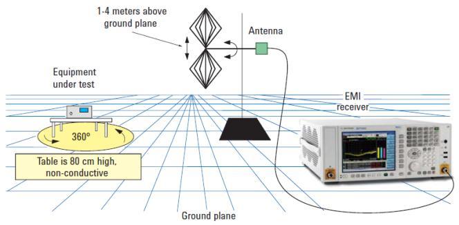
7 EMI measurement system Page 7

 or MIL-STD-461 (for military), a qualified open area test site or semi anechoic chamber and an antenna tower and turntable to maximize EUT signals.")
8 Pre-compliance vs. Full compliance measurements Pre-compliance measurements Evaluate the conducted and radiated emissions of a device using correct detectors and bandwidths before going to a test house for compliance testing Full Compliance measurements Full compliance testing requires a receiver that meets the requirements of CISPR part (for commercial) or MIL-STD-461 (for military), a qualified open area test site or semi anechoic chamber and an antenna tower and turntable to maximize EUT signals. EMI receivers require a pre-selector at lower frequencies to limit the input energy and maintain sufficient dynamic range to meet the CISPR 16 requirements. Page 8
9 Compliance EMI receiver requirements A CISPR receiver must have the following functionality in the range 9 khz - 18 GHz: A normal +/- 2 db absolute accuracy CISPR-specified resolution bandwidths (-6 db) Peak, quasi-peak, EMI average, and RMS average detectors Specified input impedance with a nominal value of 50 ohms; deviations specified as VSWR Be able to pass product immunity in a 3 V/m field Be able to pass the CISPR pulse test (implies pre-selector below 1 GHz) Other specific harmonic and intermodulation requirements Page 9


10 CISPR Pulse Generator for Testing the QP response Purpose of the Schwarzbeck generator Schwarzbeck Pulse Generator Establish the reference repetition rate for band A, B, C and D using QPD The repetition rate can be varied between 1000 Hz and an isolated pulse The relative equivalent level can be adjusted Page 10
11 Receiver requirements above 1 GHz Above 1 GHz regulations require: 1 MHz bandwidth for measurements No quasi-peak detector No CISPR pulse test, meaning no additional pre-selector required excellent sensitivity According to current FCC regulations, the maximum test frequency is the fifth harmonic of the highest clock frequency for an unintentional radiator (for example, computers without wireless connectivity) and the tenth harmonic for an intentional radiator (such as a cellular phone or wireless LAN). Page 11

12 What is an EMI Receiver? Let s begin with a spectrum analyzer Spectrum Analysis Display and measure amplitude versus frequency for RF & MW signals Separate or demodulate complex signals into their base components (sine waves) Page 12


13 Overview Types of Tests Made Modulation EMC Noise Distortion Page 13
14 Theory of Operation Swept Spectrum Analyzer Block Diagram RF input attenuator mixer IF gain IF filter (RBW) envelope detector Input signal Pre-Selector Or Low Pass Input Filter local oscillator Log Amp video filter sweep generator Crystal Reference Oscillator ADC, Display & Video Processing Page 14

15 RF Pre-selection (RF input filtering) Purpose of RF pre-selection Help to prevent overload by reducing the total energy at the input mixer The RF preselector tracks the center frequency of the EMI receiver The bandwidth of the RF preselector is wider that the widest RBW used Useful in measuring broadband signals Narrow band signals Broadband signals Page 15
16 Traditional Spectrum Analyzer Scalar analysis Digitizing the video signal Product detector loss of phase information Classic superheterodyne swept spectrum analyzer 16

17 Digital IF Spectrum/Signal Analyzer Vector data CAN be preserved (mag/phase or I/Q) Digitizing the IF Signal Some troublesome operations and conversions are now fast, accurate DSP 17


18 Specifications Resolution: RBW Type Determines Sweep Time 8563E Analog RBW PSA Digital RBW PSA FFT RBW 280 sec 134 sec 13.5 sec Page 18
19 Speed Improvements Nominal speed comparison, PSA example: Benchmark PXA PSA Useful comparisons highly specific, many factors PXA mode switching typically faster than PSA Speed improvement Preset (*RST) 28 ms 168 ms 6x Marker peak search 6.5 ms 78 ms 12x Local Update 13 ms 17 ms 1.3x CF Tune and Transfer (4-5GHz) 109 ms 186 ms 1.7x Remote sweep and trace transfer 18 ms 30 ms 1.67x Where speed is critical, consider modifying measurement routines to include features such as list sweep 19
20 Modern spectrum analyzer Resolution BW Selectivity or Shape Factor 3 db 3 db BW 60 db 60 db BW Selectivity = 60 db BW 3 db BW Determines resolvability of unequal amplitude signals Page 20
21 Specifications Resolution: RBW Type and Selectivity ANALOG FILTER Typical Selectivity Analog 15:1 Digital 5:1 DIGITAL FILTER RES BW 100 Hz SPAN 3 khz Page 21

22 Digital Filter Shape Better shape factor, biggest selectivity benefit for different signal levels Equivalent selectivity at a wider, faster-sweeping RBW digital filters swept an additional 3-4x faster 30 khz Digital Filter 22
23 CISPR Bandwidth Requirements Bandwidth -6dB -20dB Measurement Range CISPR Band CISPR Bandwidth 9 KHz 150KHz A 200 Hz 150 KHz 30 MHz B 9 KHz 30 MHz 1 GHz C/D 120 KHz > 1GHz E 1 MHz Page 23
24 CISPR Bandwidth Requirements, cont Band A filter Page 24
25 MIL-STD-461 Bandwidth Requirements Measurement Range -6dB Bandwidth 30Hz - 1 KHz 10 Hz 1 KHz -10 KHz 100 Hz 10 KHz KHz 1 KHz 150 KHz - 30MHz 10 KHz 30 MHz - GHz 100 KHz > 1GHz 1 MHz Page 25

26 Detectors: Convert IF Samples to Display Bins or Buckets Multiple simultaneous detectors Peak, Neg Peak, Sample Display points or buckets Peak Normal, Average, Neg Peak Volts Sample Neg Peak Screen Shot Detector 3types Time 26
27 Detectors Most radiated and conducted limits are based on quasi-peak detection mode. Page 27
28 Peak vs. Quasi-peak vs. Average V Peak Detection Quasi-Peak Detection Average Detection V time Peak Detection time Quasi-Peak Detection Average Detection Page 28


29 Peak QP Average Peak Detector Initially used Faster than QP and Average modes If all signals fall below the limit, then the product passes and no future testing is needed. QP For CW signal, Peak = QP Much slower by 2 or 3 order magnitude compared to using Peak detector Charge rate much faster than discharge rate the higher repetition rate of the signal, the higher QP reading Average Radiated emissions measurements above 1 GHz are performed using average detection Page 29
30 EMI Receiver Detectors (cont d) EMI Average Detection This is the response to a pulse by the average detector RMS Average Detection RMS-average weighting receivers employ a weighting detector that is a combination of the rms detector (for pulse repetition frequencies above a corner frequency fc) and the average detector (for pulse repetition frequencies below the corner frequency fc), thus achieving a pulse response curve with the following characteristics: 10 db/decade above the corner frequency and 20 db/decade below the corner frequency. Page 30
31 Modern Spectrum Analyzer Accuracy Some modern analyzers approach accuracy of power meter + sensor Even better for low-level signals, with narrower noise bandwidth and the benefit of frequency selectivity Some factors determining uncertainty: Input connector (mismatch) RF input attenuator Mixer and input filter (flatness) IF gain/attenuation (reference level) RBW filters Display scale fidelity Calibrator 31
32 Modern Spectrum Analyzer - Specifications Digital IF provides power meter like accuracy Page 32
33 Line Impedance Stabilization Networks (LISN) Purpose of a LISN: 1. Isolates the power mains from the equipment under test. The power supplied to the EUT must be as clean as possible. Any noise on the line will be coupled to the X-Series signal analyzer and interpreted as noise generated by the EUT. 2. Isolates any noise generated by the EUT from being coupled to the power mains. Excess noise on the power mains can cause interference with the proper operation of other devices on the line. 3. The signals generated by the EUT are coupled to the X-Series analyzer using a high-pass filter, which is part of the LISN. Signals that are in the pass band of the high-pass filter see a 50-Ω load. Page 33

34 LISN Page 34
35 Electrical Network 150 khz to 30 MHz Page 35

36 Transient Limiter The purpose of the limiter is to protect the input of the EMC analyzer from large transients when connected to a LISN. Switching EUT power on or off can cause large spikes generated in the LISN. Limiter LISN The Agilent 11947A transient limiter incorporates a limiter, high-pass filter, and an attenuator. It can withstand 10 kw for 10 μsec and has a frequency range of 9 khz to 200 MHz. The high-pass filter reduces the line frequencies coupled to the EMC analyzer. Page 36 DUT
37 Field Strength Unit Radiated EMI emissions measurements measure the electric field. The field strength is calibrated in dbμv/m. Pt = total power radiated from an isotropic radiator Pd = the power density at a distance from the isotropic radiator (far field >λ/2π) P d Pt 4 r 2 E R 2 Pt 4 r 2 R 120 [ohm] Free Space Impedance 2 E P d R r E Pt 30 r [V/m] Page 37
38 Field Strength and Antenna factors Radiated EMI emissions tests measure the electric field. The field strength is calibrated in dbμv/m. Antenna factors is the ratio of the electric field (V/m) present at the plane of the antenna versus the voltage out of the antenna connector. Log units: AF(dB/m) = E(dBμV/m) - V(dBμV) E(dBμV/m) = V(dBμV) + AF(dB/m) Notes: Antenna factors are not the same as antenna gain. dbμv = dbm Page 38


39 Broadband antenna examples Double ridged horn antennas Biconical antenna Log Periodic antenna Hybrid log periodic Hybrid log periodic Page 39
40 EMC Regulations An Overview Page 40
41 Standard Setting Institutions CISPR (International Special Committee on Radio Interference) IEC* 174 Technical committees and subcommittees CENELEC European standards organization TC77 (Technical Committee 77) deals with EMC FCC Federal Communication Commission ANSI American National Standards Institute *IEC International Electrotechnical Commission Page 41
42 Frequency Bands for Conducted and Radiated Emission Mil-STD Radiated (RE101, RE102) Mil-STD Mil-STD Conducted (CE106) or Mil-STD Radiated (RE103) Mil-STD Conducted (CE101, CE102) Commercial CISPR Radiated FCC Radiated CISPR, FCC conducted 30Hz 9 khz 10 MHz 30 MHz 10 khz 18GHz To 40 GHz RE103 may be used as an alternative for CE106 when testing transmitters with their intended antennas. CE106 is the preferred requirement unless the equipment or subsystem design characteristics preclude its use. Page 42 Page 年 9 月 5 日星期一 Sun Tong
43 Who must comply with EMC Directive Manufacturers of electronic equipment such as: ITE (information technology equipment) ISM (industrial, scientific medical) Broadcast receivers Household appliances and tools Luminaries and fluorescent lighting If a product does not fit into one of the above categories then it must follow the generic standard Page 43
44 National Regulations Summary for Radiated and Conducted Emissions CISPR FCC EN Description 11 Part 18 EN55011 ISM equipment 12 (SAE) EN55012 Vehicles off board rec. 13 Part 15 EN55013 Broadcast receivers 14 EN55014 Household appliances 15 EN55015 Luminaries (fluorescent lights) 16 Receivers/Methods 22 Part 15 EN55022 IT Equipment 25 EN55025 Vehicle on board rec. Page 44
45 European Norms example EN55014 (CISPR 14) This standard applies to electric motor-operated and thermal appliances for household and similar purposes, electric tools and electric apparatus. Limit line use depends upon the power rating of the item. EN55014 distinguishes between household appliances, motors less than 700W, less than 1000W and greater than 1000W. Limits for conducted emissions are 150 khz to 30 MHz, and limits for radiated emissions are 30 MHz to 300 MHz Page 45
46 MIL-STD 461 Bandwidths and Measurement Times Page 46
47 EMC Testing During Product Life Cycle Page 47


48 The Need for a Complete EMC Test Strategy Why Not Just Build the product then test it? The chances of passing compliance testing is less than 10% The cost of failure: Market window lost (Competitor beats you to market) Additional engineering time Cost of fixes to pass emissions Cost of retesting Page 48
49 EMI problem costs Breadboard/Design Prototype Production The Cost of EMI solutions as the project progresses Project development time line Page 49
50 Compliance Testing for Emissions 50
51 General Process for Making EMI Measurements Determine the country or countries in which the product will be sold which in turn identifies the regulatory agency. Select the limit lines to be tested to (conducted/radiated). Select the band to be used. Correct for transducer loses and amplifiers gains. Identify signals above the limit that must be evaluated. Zoom in on failed signal and perform quasi-peak or average measurements. Page 51

52 Conducted Emissions Measurements 1. Connect DUT to the test system 2. Set the proper frequency range 3. Load limit lines and correction factors for LISN and limiter 4. View the ambient emissions with DUT OFF 5. Switch on the DUT and find signals above limits by using peak detector 6. Measure all signals above limits with quasi-peak and average detectors Page 52
53 Page 53

 and the")


54 The challenge of measuring radiated emissions Radiated Emissions are difficult to measure because of multiple dimensions (five) and the use of quasi-peak detection below 1GHz 5 -Time 1 - Azimuth 2 - Antenna Height 3 - Field Strength MHz MHz MHz 4 - Frequency Page 54


55 Examples of Test Facilities Open Area Test Site (OATS) Useful in low ambient signal environments GHz Transverse Electro Magnetic Cell (GTEM Cell) Used for smaller devices. Can be used for immunity and emissions. Page 55
56 GTEM Cell details RF output for emissions testing or RF input for immunity testing DUT Area Septum terminated in 50 ohms RF absorbers Page 56
 *Anechoic material are made of carbon impregnated rubberized cones or")
57 Test Facilities (cont d) 10 Meter Semi Anechoic* Chamber This chamber uses 2 antenna towers, one for vertical and one for horizontal polarization. Uses a ground plan. Reverberation Chamber Uses a mode stirring tuner to generate a uniform field (no absorption material on the walls) *Anechoic material are made of carbon impregnated rubberized cones or ferrite tiles or both Page 57
58 Radiated Emissions Measurements 1. Connect the antenna to the EMI receiver and separate the antenna from the DUT as specified by the regulation requirements 2. Set the proper frequency range and bandwidth 3. Load limit lines and correction factors for antenna and cable. 4. With DUT OFF, measure the ambient emissions and store them 5. Switch on the DUT and find signals above limits by using peak detector (only those not present during the ambient scan). Rotate the DUT to maximize the emissions. 6. Measure all signals above limits with quasi-peak and average detectors Page 58

59 1. Select the measurement range Page 59
60 2. Load Corrections factors Amplitude at point circled Amplitude referenced to blue line Page 60
61 3. Load Limit line Circle indicates the position of the amplitude frequency pair Page 61
62 4. Scan for signals above the limits with peak detector Page 62

63 5. Quasi-peak and average measurements Page 63


64 Once EMC testing becomes part of the product strategy (THEN WHAT) Continue to use test houses at $$$$ per hour OR Build your own facility for M$ + Purchase and setup a precompliance system X-Series signal analyzer with N6141A /EMC app. LISN Antennas and tripod Page 64
65 Pre-compliance testing Approach Full Compliance Testing Accuracy At a fraction of the cost of full compliance testing Minimum Pre-compliance test system Pricing Product CXA Signal Analyzer to 7 GHz W6141A EMC application LISN Biconical Antenna Log Periodic Antenna Antenna Tripod Total Price Price 16.3k USD 4.1k USD 2.4k USD ~5k USD ~5k USD ~0.5k USD ~33.3k USD Page 65

66 Automation in Pre-compliance Measurements Reasons for Automation -Supplement skill and knowledge of the tester -Measurements repeatability -Results are presented in a common format -Reduce test time by automating setups Types of Automation -Internally executed application such as N6141A -PC based applications Software Available -Techcelerant, TILE from ETS Lindgren, TDK RF Solutions, Radimation from DARE Page 66

67 Pre-compliance Conducted Emissions Setup X-Series Signal Analyzer To Mains LISN DUT With N6141A EMC App Transient Limiter DUT power cord* *Keep the power cord short to avoid becoming an antenna Page 67
68 Pre-compliance Radiated Emissions Setup Perform testing in both the horizontal and vertical position 3 or 10 Meter distance DUT Ground Plane X-Series Signal Analyzer with N6141A EMC App The goal is to find and record the maximum emissions from the DUT by rotating the turn table, changing the polarization and the height of the antenna. Page 68

69 Troubleshooting Use the close-field probe to locate the sources of the radiated signals exceeding the limit lines Page 69


70 Immunity test setup Amplifiers Radiated Immunity 30 MHz 18 GHz HF-Switch Conducted Immunity 100 khz 1 GHz Page 70
71 Agilent Solutions Page 71


72 What is a CISPR Compliant Receiver CISPR is a subcommittee of the IEC CISPR is the document that defines the functionality of an EMI receiver Detectors Frequency response N9038A MXE EMI receiver is CISPR Compliant Page 72

73 EMI Receiver Requirements for Compliance Testing of Conducted and Radiated Emissions N9038A MXE Compliant receiver CISPR Hz, 9 khz, 120 khz (6 db) and 1 MHz (imp) bandwidths -Peak, Quasi-peak, EMI average, RMS average detectors -RF Pre-selection to meet CISPR pulse generator response -VSWR, 0dB and 10dB input attenuation -Amplitude Accuracy MIL-STD 461 -Peak detection only -MIL STD BWs (10 Hz, 100 Hz, 1 khz, 10 khz, 100 khz, 1 MHz) Page 73


74 What is the MXE EMI Receiver? The Agilent MXE is more than a CISPR compliant EMI receiver It is also an X-Series signal analyzer that can run a variety of measurement applications The MXE can evolve as technology changes X-Series signal analyzer CISPR 16 compliant EMI receiver Page 74


75 Agilent X-Series Signal Analyzers Multiple instruments in one box: Swept spectrum analyzer; FFT analyzer; Analog and digital modulation analyzer; Noise Figure analyzer EMI receiver Fastest signal analysis measurements Broadest set of applications and demodulation capabilities Upgradeable HW Most advanced user interface & world-class connectivity Page 75
76 All Digital IF Advantages RF Section ADC FFT IF/BB Section on ASIC Flexibility: RBW filtering in 10% steps Filters with better selectivity Multiple operation modes (Swept, FFT, VSA, NFA) Accuracy: Log conversion practically ideal No drift errors; increased repeatability Speed: When Swept mode is slow, go FFT Page 76
77 Techniques for Reducing DANL, Improving Dynamic Range Reduce attenuation Add preamp Reduce RBW Add external filtering Better/shorter cables, connectors Move analyzer closer Time averaging (where possible, not measurement avg.) Measurement processing (take advantage of Moore s Law) Noise power subtraction/noise correction/nnc Noise floor extension (NFE) leverages deep knowledge of analyzer/circuit behavior 77
78 CW Signal Measured Near Analyzer Noise Floor Example: No noise subtraction or near noise correction Apparent Signal Actual S/N Displayed S/N CW Signal Ampl & Freq Axes Expanded This is fundamental, and often missed 78
79 Noise Floor Subtraction P obss+n = P obsn + P S P S = P obss+n P obsn Analyzer noise adds incoherently to any signal to be measured Power calculations are performed on a linear power scale (watts, not dbm) and results typically are shown in dbm 79

80 Noise Subtraction, Noise Floor Extension New technique NFE improves D.A.N.L. analyzer noise power calculated/subtracted real time No error 3 db error without NFE Improved noise floor or displayed average noise level 80
 Amplitude correction (2000 pts) 40001 sweep points Page Page")
81 EMC Features standard in all X-Series Spectrum analyzers Limit Lines (2000 pts) Amplitude correction (2000 pts) sweep points Page Page 81 81
 Quasi Peak EMI Average ( CISPR-AVG ) RMS Average ( CISPR-RMS ) EMI")

82 Option EMC in X-Series spectrum analyzer CISPR detectors (to latest spec) Quasi Peak EMI Average ( CISPR-AVG ) RMS Average ( CISPR-RMS ) EMI Bandwidths (CISPR & MIL STD) EMI Presets Tune & Listen Measure at Marker EMI Peak, EMI Average, and Quasi Peak measurements displayed together Page 82


83 W/N6141A EMC measurement application Full Featured Pre-compliance Application Available in all X-Series models Page 83

84 Corrections factors edit display Amplitude at point circled Amplitude referenced to blue line Page 84
85 Limit line edit display Circle indicates the position of the amplitude frequency pair Page 85

86 Auto-detect peaks Log Display Realtime Meters with any 3 Simultaneous Detectors Peak List Limit Delta Page 86
87 N6141A measurement: Frequency Scan with Log Display Meters tune to selected signal Page 87

88 N6141A measurement: Strip Chart Time record of zero span data scrolls to left Up to three different detectors Can be used to make click measurements Patent Applied For Click measurements are made on home appliances Page 88
 for")

89 Option EDP (Enhanced Display Package) for the SA Spectrogram Trace Zoom Zone Span Page 89


90 N6141A EMI Measurement Application PXA MXA Pre-compliance EXA Compliance CXA Agilent MXE N9038A
91 Agilent products for Immunity test (EMS) Signal generator Signal generator 9 khz 3 GHz, AM, FM, Phase, Pulse IQ Modulator, 40 MHz Mod.-BW N5181B, N5182B, N5183A 9 khz- 1,3, 6, 20, 40 GHz, AM, FM, Phase, Pulse, optional vector, 120 MHz Mod.-BW, step, sweep, USB-Power meter included Power meter/ Power sensors E441x, E191x, N8262, U200x 100 khz 40 GHz single channel, dual channel, USB, peak, envelope, pulse Accessories Directional Couplers, cables, Adapters, Switches etc. Page 91
92 Solution partners for EMC Complete solution: 1. Automation software 2. Chambers 3. GTEM 4. Antennas 5. Power amplifiers 6. Accessories Page 92
93 For more information about EMC solutions from Agilent please visit: Contacts: Jan Sjogren Signal Analysis and Generation Sales Specialist Agilent Contact Center Tel: Microlease (Agilent Authorized Technology Partner) Tel: Page 93
Misure di pre-compliance EMI
 Misure di pre-compliance EMI Roberto Sacchi Application Engineer Roberto_sacchi@agilent.com Page 1 Agenda Introduzione alle misure EMI Terminologia; Sistema di misura (antenna, LISN, ricevitore, etc.);
EMC Back to Basics. Matthew Carter EMC Product Support Engineer Agilent Technologies Inc. April 16, 2014
 EMC Back to Basics Matthew Carter EMC Product Support Engineer Agilent Technologies Inc. April 16, 2014 Agilent Technologies, Inc. 2014 Agenda EMC Back to Basics Overview What is Electromagnetic Compatibility?
Utilizzo del Time Domain per misure EMI
 Utilizzo del Time Domain per misure EMI Roberto Sacchi Measurement Expert Manager - Europe 7 Giugno 2017 Compliance EMI receiver requirements (CISPR 16-1-1 ) range 9 khz - 18 GHz: A normal +/- 2 db absolute
EMC Training. Ing Angelo Cereser Mobile:
 EMC Training Ing Angelo Cereser angelo.cereser@microlease.com Mobile: 335 57 88 293 Dott Mirko Bombelli mirko.bombelli@microlease.com Mobile: 335 12 36 792 Agenda Introduzione alle misure EMI Terminologia;
ER55 EMI TEST RECEIVER Family of automatic test receivers for measurement of electromagnetic interference from 9kHz to 2.8GHz.
 ER55 EMI TEST RECEIVER Family of automatic test receivers for measurement of electromagnetic interference from 9kHz to 2.8GHz. Compact designed and manufactured in compliance with CISPR 16-1-1 For Measurements
Essential Capabilities of EMI Receivers. Application Note
 Essential Capabilities of EMI Receivers Application Note Contents Introduction... 3 CISPR 16-1-1 Compliance... 3 MIL-STD-461 Compliance... 4 Important features not required by CISPR 16-1-1 or MIL-STD-461...
Keysight Technologies Essential Capabilities of EMI Receivers. Application Note
 Keysight Technologies Essential Capabilities of EMI Receivers Application Note Contents Introduction... 3 CISPR 16-1-1 Compliance... 3 MIL-STD-461 Compliance... 4 Important features not required by CISPR
RF Fundamentals Part 2 Spectral Analysis
 Spectral Analysis Dec 8, 2016 Kevin Nguyen Keysight Technologies Agenda Overview Theory of Operation Traditional Spectrum Analyzers Modern Signal Analyzers Specifications Features Wrap-up Page 2 Overview
ER55 EMI TEST RECEIVER Family of automatic test receivers for measurement of electromagnetic interference from 9kHz to 1GHz
 ER55 EMI TEST RECEIVER Family of automatic test receivers for measurement of electromagnetic interference from 9kHz to 1GHz Compact designed and manufactured in compliance with CISPR 16-1, For Measurements
Keysight Technologies N6141A & W6141A EMI X-Series Measurement Application. Technical Overview
 Keysight Technologies N6141A & W6141A EMI X-Series Measurement Application Technical Overview EMI Measurement Application To avoid costly delays that can result from failed compliance testing, Keysight's
Advanced Compliance Solutions, Inc FAU Blvd, Suite 310 Boca Raton, Florida (561)
") 2129.01 Advanced Compliance Solutions, Inc. 3998 FAU Blvd, Suite 310 Boca Raton, Florida 33431 (561) 961-5585 Technical Report No. 09-2067a-2 EMI Evaluation of the AMM Marketing, LLC s E-Pulse UH 900,
2129.01 Advanced Compliance Solutions, Inc. 3998 FAU Blvd, Suite 310 Boca Raton, Florida 33431 (561) 961-5585 Technical Report No. 09-2067a-2 EMI Evaluation of the AMM Marketing, LLC s E-Pulse UH 900,
Advanced Test Equipment Rentals ATEC (2832)
") Established 1981 Advanced Test Equipment Rentals www.atecorp.com 800-404-ATEC (2832) R3000 EMI TEST RECEIVERS Fully IF digital EMI Receivers family for measurement of electromagnetic interference from
Established 1981 Advanced Test Equipment Rentals www.atecorp.com 800-404-ATEC (2832) R3000 EMI TEST RECEIVERS Fully IF digital EMI Receivers family for measurement of electromagnetic interference from
Test and Measurement for EMC
 Test and Measurement for EMC Bogdan Adamczyk, Ph.D., in.c.e. Professor of Engineering Director of the Electromagnetic Compatibility Center Grand Valley State University, Michigan, USA Ottawa, Canada July
Radiated Spurious Emission Testing. Jari Vikstedt
 Radiated Spurious Emission Testing Jari Vikstedt jari.vikstedt@ets-lindgren.com What is RSE? RSE = radiated spurious emission Radiated chamber Emission EMI Spurious intentional radiator 2 Spurious Spurious,
Chambers Accessories Equipment 1 Equipment 2 Amplifiers Antennas Emission
 Chambers Accessories Equipment 1 Equipment 2 Amplifiers Antennas Emission Core-6 EMI Receiver 9 khz 6 GHz Features: Frequency ranges: 9 khz 30 MHz and 30 MHz 6 GHz Fully compliant acc. to CISPR 16-1-1
FFT 3010 EMI TEST RECEIVER
 FFT 3010 EMI TEST RECEIVER Fully FFT digital EMI Receiver for measurement of conducted electromagnetic interference from 9kHz to 30MHz Compact designed and manufactured compliant to CISPR 16 International
3250 Series Spectrum Analyzer
 The most important thing we build is trust ADVANCED ELECTRONIC SOLUTIONS AVIATION SERVICES COMMUNICATIONS AND CONNECTIVITY MISSION SYSTEMS 3250 Series Spectrum Analyzer > Agenda Introduction
Understanding RF and Microwave Analysis Basics
 Understanding RF and Microwave Analysis Basics Kimberly Cassacia Product Line Brand Manager Keysight Technologies Agenda µw Analysis Basics Page 2 RF Signal Analyzer Overview & Basic Settings Overview
Advanced Test Equipment Rentals ATEC (2832)
") Established 1981 Advanced Test Equipment Rentals www.atecorp.com 800-404-ATEC (2832) Agilent E7400 A-series EMC Analyzers, Precompliance Systems, and EMI Measurement Software E7401A, E7402A E7403A, E7404A
Established 1981 Advanced Test Equipment Rentals www.atecorp.com 800-404-ATEC (2832) Agilent E7400 A-series EMC Analyzers, Precompliance Systems, and EMI Measurement Software E7401A, E7402A E7403A, E7404A
Agilent N9320B RF Spectrum Analyzer
 Agilent N9320B RF Spectrum Analyzer 9 khz to 3.0 GHz Data Sheet Definitions and Conditions The spectrum analyzer will meet its specifications when: It is within its calibration cycle It has been turned
Electromagnetic Compatibility
 Electromagnetic Compatibility Introduction to EMC International Standards Measurement Setups Emissions Applications for Switch-Mode Power Supplies Filters 1 What is EMC? A system is electromagnetic compatible
Trees, vegetation, buildings etc.
 EMC Measurements Test Site Locations Open Area (Field) Test Site Obstruction Free Trees, vegetation, buildings etc. Chamber or Screened Room Smaller Equipments Attenuate external fields (about 100dB) External
Ave output power ANT 1(dBm) Ave output power ANT 2 (dbm)
 Ave output power ANT 2 (dbm)") Page 41 of 103 9.6. Test Result The test was performed with 802.11b Channel Frequency (MHz) power ANT 1(dBm) power ANT 2 (dbm) power ANT 1(mW) power ANT 2 (mw) Limits dbm / W Low 2412 7.20 7.37 5.248 5.458
Page 41 of 103 9.6. Test Result The test was performed with 802.11b Channel Frequency (MHz) power ANT 1(dBm) power ANT 2 (dbm) power ANT 1(mW) power ANT 2 (mw) Limits dbm / W Low 2412 7.20 7.37 5.248 5.458
EMC/EMI MEASURING INSTRUMENTS & ACCESSORIES SHORT-FORM CATALOG 2011
 EMC/EMI MEASURING INSTRUMENTS & ACCESSORIES SHORT-FORM CATALOG 2011 All-in-one Digital EMI Analyzer 10 Hz - 3 GHz PMM 9010/30P EMI Analyzer 10 Hz - 3 GHz Our trek started in a small laboratory over 25
EMC Precompliance Systems and Accessories Catalog
 EMC Precompliance Systems and Accessories Catalog Agilent 84115EM EMC precompliance systems Agilent E7402A and E7405A EMC precompliance analyzers Agilent E7415A EMC measurement software Agilent EMC precompliance
Page 1 of 51 Report No.: T TEST REPORT FCC ID: 2AGJ5WAP-30. In Accordance with: FCC PART 15, SUBPART C : 2015 (Section 15.
 Page 1 of 51 Report No.: T1851663 01 TEST REPORT FCC ID: 2AGJ5WAP-30 Applicant Address : Gonsin Conference Equipment Co., Ltd : No.401-406,Block C, Idea Industry Park, No.41 Fengxiang Road, Shunde, Foshan,
Keysight Technologies N9320B RF Spectrum Analyzer
 Keysight Technologies N9320B RF Spectrum Analyzer 9 khz to 3.0 GHz Data Sheet Definitions and Conditions The spectrum analyzer will meet its specifications when: It is within its calibration cycle It has
Specification for Conducted Emission Test
 1 of 10 1. EMI Receiver Frequency range 9kHz 7.0 GHz Measurement time per frequency 10 µs to 100 s time sweep, span = 0 Hz - 1 µs to 16000 s Sweep time in steps of 5 % frequency sweep, span 10 Hz - 2.5
7. Transmitter Radiated Spurious Emissions and Conducted Spurious Emission
 7. Transmitter Radiated Spurious Emissions and Conducted Spurious Emission 7.1 Test Setup Refer to the APPENDIX I. 7.2 Limit According to 15.247(d), in any 100 khz bandwidth outside the frequency band
Overview of EMC Regulations and Testing. Prof. Tzong-Lin Wu Department of Electrical Engineering National Taiwan University
 Overview of EMC Regulations and Testing Prof. Tzong-Lin Wu Department of Electrical Engineering National Taiwan University What is EMC Electro-Magnetic Compatibility ( 電磁相容 ) EMC EMI (Interference) Conducted
The Value of Pre-Selection in EMC Testing. Scott Niemiec Application Engineer
 The Value of Pre-Selection in EMC Testing Scott Niemiec Application Engineer Video Demonstrating Benefit of Pre-selection 400MHz -1GHz Sweep with RBW = 120kHz Yellow: w/ preselection Green: w/o pre-selection
PMM 7010 EMI RECEIVERS. The EMI Receiver with built-in LISN
 The EMI Receiver with built-in LISN 1 Model Frequency Range 7010/00 150 khz to 1 GHz 7010/01 9 khz to 1 GHz 7010/02 9 khz to 30 MHz 7010/03 9 khz to 3 GHz 2 family Built-in 16 A single phase LISN Artificial
Advanced Test Equipment Rentals ATEC (2832)
") Established 1981 Advanced Test Equipment Rentals www.atecorp.com 800-404-ATEC (2832) EMI Testing According to CSPR Publication 16 Recommendations Combining the 85685A RF preselector with the 8566B or 8568B
Established 1981 Advanced Test Equipment Rentals www.atecorp.com 800-404-ATEC (2832) EMI Testing According to CSPR Publication 16 Recommendations Combining the 85685A RF preselector with the 8566B or 8568B
EMC/EMI MEASURING INSTRUMENTS & ACCESSORIES SHORT-FORM CATALOG 2009
 EMC/EMI MEASURING INSTRUMENTS & ACCESSORIES SHORT-FORM CATALOG 2009 Our trek started in a small laboratory over 25 years ago. Since then, we ve been focused on making EMC measurements easier and the measuring
FCC Certification Test Report for the MEI Cashflow RFID Reader Base FCC ID: QP8EASITRAXRB
 for the FCC ID: QP8EASITRAXRB WLL JOB# 9915 September 21, 2007 Prepared for: 1301 Wilson Drive West Chester, PA 19380 Prepared By: Washington Laboratories, Ltd. 7560 Lindbergh Drive Gaithersburg, Maryland
TABLE OF CONTENTS 1. GENERAL INFORMATION... 4
 TABLE OF CONTENTS 1. GENERAL INFORMATION... 4 1.1. EUT DESCRIPTION... 4 1.2. TEST STANDARDS AND RESULTS... 5 1.3. FACILITIES AND ACCREDITATIONS... 6 1.3.1. FACILITIES... 6 1.3.2. TEST ENVIRONMENT CONDITIONS...
Understanding Probability of Intercept for Intermittent Signals
 2013 Understanding Probability of Intercept for Intermittent Signals Richard Overdorf & Rob Bordow Agilent Technologies Agenda Use Cases and Signals Time domain vs. Frequency Domain Probability of Intercept
RF Emissions Test Report To Determine Compliance With: FCC, Part 15 Rules and Regulations
 RF Emissions Test Report To Determine Compliance With: FCC, Part 15 Rules and Regulations Model numbers: HT130022 Rev. B. December 17, 2002 Manufacturer: HQ, Inc. 210 9th Steet Drive Palmetto, FL 34221
Agilent X-Series Signal Analyzer
 Agilent X-Series Signal Analyzer This manual provides documentation for the following analyzers: PXA Signal Analyzer N9030A MXA Signal Analyzer N9020A EXA Signal Analyzer N9010A CXA Signal Analyzer N9000A
TRANSMITTER MODEL: KAS-2030M
 Page 1 of 16 FCC PART 15, SUBPART B and C TEST REPORT for TRANSMITTER MODEL: KAS-2030M Prepared for WILDLIFE TECHNOLOGIES 115 WOLCOTT STREET MANCHESTER, NEW HAMPSHIRE 03103 Prepared by: KYLE FUJIMOTO Approved
L.S. Compliance, Inc. W66 N220 Commerce Court Cedarburg, WI
 L.S. Compliance, Inc. W66 N220 Commerce Court Cedarburg, WI 53012 262-375-4400 COMPLIANCE TESTING OF: Quartex Synchronization Transmitter Model FM-72 PREPARED FOR: Quartex, Division of Primex, Inc. 965
Compliance Engineering Ireland Ltd
 Page 1 of 27 Compliance Engineering Ireland Ltd RAYSTOWN, RATOATH ROAD, ASHBOURNE, CO. MEATH, IRELAND Tel: +353 1 8256722 Fax: +353 1 8256733 Project Number: 10E2475-5 Prepared for: Biancamed Ltd By Compliance
A Study of Conducted-Emission Stable Source Applied to the EMC US and EU Standards
 Fourth LACCEI International Latin American and Caribbean Conference for Engineering and Technology (LACCEI 2006) Breaking Frontiers and Barriers in Engineering: Education, Research and Practice, 21-23
Page: 1 of 20 EMC TEST REPORT EN55024:1998+A2:2003
 Page: 1 of 20 EMC TEST REPORT Reference No. Applicant : WT05060412 : Gembird Electronics Ltd. Equipment Under Test (EUT) : Product Name : Cable Standards Model No : UAS111-M, UAS111, UAS112 : EN55022:1998+A2:2003
FCC ID: B4OCC264BPA-S
 FCC TEST REPORT FCC ID: B4OCC264BPA-S Product : Bluetooth LE Module Model Name : CC264BPA-S, CC265BPA-S, CC26xBPA Brand : GT-tronics Report No. : PTC801181160622E-FC01 Prepared for GT-tronics HK Ltd Unit
Spectrum Analyzers 2680 Series Features & benefits
 Data Sheet Features & benefits n Frequency range: 9 khz to 2.1 or 3.2 GHz n High Sensitivity -161 dbm/hz displayed average noise level (DANL) n Low phase noise of -98 dbc/hz @ 10 khz offset n Low level
APPLICATION FOR CERTIFICATION On Behalf of Futaba Corporation Radio Control Model No.:T10CG-2.4G FCC ID:AZPT10CG-24G Brand : Futaba
 FCC ID. AZPT10CG-24G Page 1 of 56 APPLICATION FOR CERTIFICATION On Behalf of Futaba Corporation Radio Control Model No.:T10CG-2.4G FCC ID:AZPT10CG-24G Brand : Futaba Prepared for : Futaba Corporation 1080
FCC PART 15 Subpart C EMI MEASUREMENT AND TEST REPORT
 FCC PART 15 Subpart C EMI MEASUREMENT AND TEST REPORT For EASTWELL ENTERPRISE (HK) LTD. RM. 12, 2/F BLOCK B NEW TRADE PLAZA, 6 ON PING STREET SHATIN NT, HONG KONG January 7, 2003 This Report Concerns:
Revision history. Revision Date of issue Test report No. Description KES-RF-14T0042 Initial
 Page (2 ) of (34) Revision history Revision Date of issue Test report No. Description - 2014.08.25 Initial Page (3 ) of (34) TABLE OF CONTENTS 1. General information... 4 1.1. EUT description... 4 1.2.
Demo / Application Guide for DSA815(-TG) / DSA1000 Series
 / DSA1000 Series") Demo / Application Guide for DSA815(-TG) / DSA1000 Series TX1000 Mobile Phone Frontend Mixer Bandpass Filter PA The schematic above shows a typical front end of a mobile phone. Our TX1000 RF Demo Kit shows
Demo / Application Guide for DSA815(-TG) / DSA1000 Series TX1000 Mobile Phone Frontend Mixer Bandpass Filter PA The schematic above shows a typical front end of a mobile phone. Our TX1000 RF Demo Kit shows
CHAPTER 6 EMI EMC MEASUREMENTS AND STANDARDS FOR TRACKED VEHICLES (MIL APPLICATION)
") 147 CHAPTER 6 EMI EMC MEASUREMENTS AND STANDARDS FOR TRACKED VEHICLES (MIL APPLICATION) 6.1 INTRODUCTION The electrical and electronic devices, circuits and systems are capable of emitting the electromagnetic
147 CHAPTER 6 EMI EMC MEASUREMENTS AND STANDARDS FOR TRACKED VEHICLES (MIL APPLICATION) 6.1 INTRODUCTION The electrical and electronic devices, circuits and systems are capable of emitting the electromagnetic
EMC Test Facility Sale
 EMC Test Facility Sale Radiated Emissions Pre-Compliance Conducted Emissions Full-Compliance Radiated & Conducted Immunity Full-Compliance 1 Please find an information pack attached for an EMC test facility.
MIL-STD 461F Results for M&A Technology Companion epad Computer
 11 July 11 MIL-STD 461F Results for M&A Technology Companion epad Computer Prepared For: Mike Lehner M&A Technology Chenault Dr Carrolton, TX 6 Prepared By: John C. Zentner Test Engineer Integrated Demonstrations
Calibration and Validation for Automotive EMC
 Calibration and Validation for Automotive EMC Wolfgang Müllner Patrick Preiner Alexander Kriz Seibersdorf Labor GmbH 2444 Seibersdorf, Austria http://rf.seibersdorf-laboratories.at rf@seibersdorf-laboratories.at
UNIDEN AMERICA CORPORATION 4700 AMON CARTER BLVD. FORT WORTH TEXAS UNITED STATES
 849 NW STATE ROAD 45 NEWBERRY, FL 32669 USA PH: 888.472.2424 OR 352.472.5500 FAX: 352.472.2030 EMAIL: INFO@TIMCOENGR.COM HTTP://WWW.TIMCOENGR.COM TEST REPORT PER FCC Part 15, Subparts B, C, and D IC RSS-213
EMI -- T E S T R E P O R T
 Registration No. DAT-P-207/05 EMI -- T E S T R E P O R T - FCC Part 15B - Test Report No. : T32619-00-04HU 24. July 2008 Date of issue Type / Model Name : R-PO7470 Product Description : Handheld Reader
OUTDOOR SOUND MODULE/TRANSMITTER MODEL: THE BANDIT
 Page 1 of 16 FCC PART 15, SUBPART B and C TEST REPORT for OUTDOOR SOUND MODULE/TRANSMITTER MODEL: THE BANDIT Prepared for MINASKA OUTDOORS 6517 PLATTE AVENUE LINCOLN, NEBRASKA 68507 Prepared by: KYLE FUJIMOTO
Interference Analysis and Spectrum Monitor Seminar
 Interference Analysis and Spectrum Monitor Seminar Handheld RF & Microwave Instruments Andrew Benn Business Development Manager Agilent Technologies Wednesday 12 th October 2011 1 Agilent Technologies,
Federal Communications Commission Office of Engineering and Technology Laboratory Division
 April 9, 2013 Federal Communications Commission Office of Engineering and Technology Laboratory Division Guidance for Performing Compliance Measurements on Digital Transmission Systems (DTS) Operating
DSA700 Series Spectrum Analyzer
 DSA700 Series Spectrum Analyzer Product Features: All-Digital IF Technology Frequency Range from 100 khz up to 1 GHz Min. -155 dbm Displayed Average Noise Level (Typ.) Min.
FCC Certification Test Report For the Mars Electronics (MEI) easitrax FCC ID: QP8EASITRAX
 easitrax FCC ID: QP8EASITRAX") For the FCC ID: QP8EASITRAX WLL JOB# 9554 April 19, 2007 Prepared for: 1301 Wilson Drive West Chester, PA 19380 Prepared By: Washington Laboratories, Ltd. 7560 Lindbergh Drive Gaithersburg, Maryland 20879
For the FCC ID: QP8EASITRAX WLL JOB# 9554 April 19, 2007 Prepared for: 1301 Wilson Drive West Chester, PA 19380 Prepared By: Washington Laboratories, Ltd. 7560 Lindbergh Drive Gaithersburg, Maryland 20879
EXHIBIT 7: MEASUREMENT PROCEDURES Pursuant 47 CFR 2.947
 EXHIBIT 7: MEASUREMENT PROCEDURES Pursuant 47 CFR 2.947 7.1 RF Power -- Pursuant to 47 CFR 2.947(c) Method of Conducted Output Power Measurement: Adaptation of TIA/EIA-603-A clause 2.2.1 for Pulsed Measurements
8 Hints for Better Spectrum Analysis. Application Note
 8 Hints for Better Spectrum Analysis Application Note 1286-1 The Spectrum Analyzer The spectrum analyzer, like an oscilloscope, is a basic tool used for observing signals. Where the oscilloscope provides
King Pigeon Communication Co., Limited
 APPLICATION FOR ELECTROMAGNETIC COMPATIBILITY DIRECTIVE On Behalf of King Pigeon Communication Co., Limited Remote Controller RTU Model No.: S130, S140, S150, S180, S25x, S26x, S27x, RTU501x, RTU502x,
EMC Accessories Catalog
 EMC Accessories Catalog Transducers and Accessories Agilent 11966 Series Antennas Agilent 11967 Series Conducted EMC Accessories Agilent 11968 Series EMC Positioning Accessories A fully equipped electromagnetic
8 Hints for Better Spectrum Analysis. Application Note
 8 Hints for Better Spectrum Analysis Application Note 1286-1 The Spectrum Analyzer The spectrum analyzer, like an oscilloscope, is a basic tool used for observing signals. Where the oscilloscope provides
8370 Court Avenue, Suite B-1 Ellicott City, Maryland (410) FCC CERTIFICATION
 FCC CERTIFICATION") IKUSI FCC INFORMATION RF Measurement Report Prepared by:: National Certification Laboratory 8370 Court Avenue, Suite B-1 Ellicott City, Maryland 21043 (410) 461-5548 IIn Supportt off:: FCC CERTIFICATION
IKUSI FCC INFORMATION RF Measurement Report Prepared by:: National Certification Laboratory 8370 Court Avenue, Suite B-1 Ellicott City, Maryland 21043 (410) 461-5548 IIn Supportt off:: FCC CERTIFICATION
EMI T E S T R E P O R T
 EMI T E S T R E P O R T - FCC Part 15B - Test Report No. : T38935-00-02TK 27. November 2014 Date of issue Type / Model Name : One Touch Select Plus Flex Product Description : Blood glucose meter with Bluetooth
OPEN TEM CELLS FOR EMC PRE-COMPLIANCE TESTING
 1 Introduction Radiated emission tests are typically carried out in anechoic chambers, using antennas to pick up the radiated signals. Due to bandwidth limitations, several antennas are required to cover
Semi Anechoic Chamber (SAC)
") 1 of 9 Semi Anechoic Chamber (SAC) Approximate Dimensions of 3m Semi Anechoic Chamber (SAC) Length: 10m Width: 9m Height: 9m Frequency range of Semi Anechoic Chamber: 9 KHz to 40 GHz Emission test (EMI):
1 of 9 Semi Anechoic Chamber (SAC) Approximate Dimensions of 3m Semi Anechoic Chamber (SAC) Length: 10m Width: 9m Height: 9m Frequency range of Semi Anechoic Chamber: 9 KHz to 40 GHz Emission test (EMI):
Signal Detection with EM1 Receivers
 Signal Detection with EM1 Receivers Werner Schaefer Hewlett-Packard Company Santa Rosa Systems Division 1400 Fountaingrove Parkway Santa Rosa, CA 95403-1799, USA Abstract - Certain EM1 receiver settings,
Specification for Radiated susceptibility Test
 1 of 11 General Information on Radiated susceptibility test Supported frequency Range : 20MHz to 6GHz Supported Field strength : 30V/m at 3 meter distance 100V/m at 1 meter distance 2 of 11 Signal generator
Global EMC Inc. Labs EMC & RF Test Report TVTXP916A04
 Global EMC Inc. Labs EMC & RF Test Report As per RSS 210 Issue 8:2010 & FCC Part 15 Subpart C:2013 Unlicensed Intentional Radiators on the Min Xie Project Engineer 11 Gordon Collins Dr, Gormley, ON, L0H
EMC ANECHOIC CHAMBERS 5-METER CHAMBERS
 ETS-Lindgren's FACT 5 Chambers offer semi-anechoic radiated emissions (RE) and fully anechoic radiated immunity (RI) compliance test capability for most international EMC compliance regulations. FACT 5
Conducted emission pre compliance measurements
 V1.1 Conducted emission pre compliance measurements All electronic products need to be tested for electromagnetic emissions that may negatively effect the correct operation of other equipment nearby. Electromagnetic
EMI Measuring Receiver & Analyzer 10 Hz-3 GHz
 Established 1981 Advanced Test Equipment Rentals www.atecorp.com 800-404-ATEC (2832) PMM 9010/30P EMI Measuring Receiver & Analyzer 10 Hz-3 GHz Full CISPR 16-1-1 Compliant 9 khz-30 MHz Field Upgradable
Table of Contents 1. GENERAL INFORMATION SYSTEM TEST CONFIGURATION CONDUCTED EMISSIONS TEST RADIATED EMISSION TEST...
 Table of Contents 1. GENERAL INFORMATION... 4 1.1 PRODUCT DESCRIPTION FOR EQUIPMENT UNDER TEST... 4 1.2 RELATED SUBMITTAL(S) / GRANT (S)... 7 1.3 TEST METHODOLOGY... 7 1.4 EQUIPMENT MODIFICATIONS... 7
Version TEST REPORT NO. DATE DESCRIPTION
 Version NO. DATE DESCRIPTION HCTR1302FR13 February 14, 2013 - First Approval Report - Additional Model Name Page 2 of 25 Table of Contents 1. GENERAL INFORMATION... 4 2. EUT DESCRIPTION... 4 3. TEST METHODOLOGY...
Sunlight Supply, Inc.
 FCC Part 18 Subpart C Non-Consumer For RF Lighting Equipment Electromagnetic Compatibility Test Report Sunlight Supply, Inc. Commercial Ballast 1000 Watt - July 18, 2017 Tests Conducted by:, LLC 20811
TEST REPORT... 1 CONTENT...
 CONTENT TEST REPORT... 1 CONTENT... 2 1 TEST RESULTS SUMMARY... 3 2 EMC RESULTS CONCLUSION... 4 3 LABORATORY MEASUREMENTS... 6 4 EMI TEST... 7 4.1 CONTINUOUS CONDUCTED DISTURBANCE VOLTAGE TEST... 7 4.2
Electromagnetic Compatibility Test Report FCC test results of an automatic dog brush, model EUT: Type 1 AC/DC adaptor: SYS W2E
 Electromagnetic Compatibility Test Report FCC test results of an automatic dog brush, model EUT: Type 1 AC/DC adaptor: SYS1308-1809-W2E Customer Customer's representative In the capacity of Reference number
EXHIBIT 10 TEST REPORT. FCC Parts 2 & 24
 EXHIBIT 10 TEST REPORT FCC Parts 2 & 24 SUB-EXHIBIT 10.1 MEASUREMENT PER SECTION 2.1033 (C) (14) OF THE RULES SECTION 2.1033 (c) (14) The data required by Section 2.1046 through 2.1057, inclusive, measured
E M C T E S T Y O U R SOURCE FOR TOP Q U A L I T Y TEST EQUIPMENT & E M C. w w w. h v t e c h n o l o g i e s. c o m
 E M C T E S T S O L U T I O N S P A R T N E R S F O R H V & E M C S O L U T I O N S Y O U R SOURCE FOR TOP Q U A L I T Y TEST EQUIPMENT w w w. h v t e c h n o l o g i e s. c o m Transient Immunity Generators
RADIATED EMISSIONS MEASUREMENTS IN AN OPEN AREA TEST SITE
 RADIATED EMISSIONS MEASUREMENTS IN AN OPEN AREA TEST SITE Dennis Handlon Agilent Technologies 1400 Fountaingrove Parkway, Santa Rosa CA 95403 Telephone 707 577 4206, dennis_handlon@non.agilent.com Abstract:
EMC TEST REPORT For MPP SOLAR INC Inverter/ Charger Model Number : PIP 4048HS
 EMC-E20130903E EMC TEST REPORT For MPP SOLAR INC Inverter/ Charger Model Number : PIP 4048HS Prepared for : MPP SOLAR INC Address : 4F, NO. 50-1, SECTION 1, HSIN-SHENG S. RD. TAIPEI, TAIWAN Prepared by
ESA-E Series Spectrum Analyzer
 ESA-E Series Spectrum Analyzer Data Sheet Available frequency ranges: E4402B 9 khz to 3.0 GHz E4404B 9 khz to 6.7 GHz E4405B 9 khz to 13.2 GHz E4407B 9 khz to 26.5 GHz Table of Contents Definitions of
FCC 15B Test Report. : BTv4.0 Dual Mode USB Dongle. Address : Thompson Ave. / Lenexa, Kansas / / USA
 FCC 15B Test Report Equipment Model No. Brand Name Applicant : BTv4.0 Dual Mode USB Dongle : BT820 : Laird Technologies : Laird Technologies Address : 11160 Thompson Ave. / Lenexa, Kansas / 66219 / USA
An Introduction to FFT EMI Receivers
 An Introduction to FFT EMI Receivers Introduction An evolution in EMI receiver design is underway to take advantage of today s digital signal processing (DSP) technologies, using fast Fourier transform
Agilent ESA-L Series Spectrum Analyzers
 Agilent ESA-L Series Spectrum Analyzers Data Sheet Available frequency ranges E4403B E4408B 9 khz to 1.5 GHz 9 khz to 3.0 GHz 9 khz to 26.5 GHz As the lowest cost ESA option, these basic analyzers are
OPEN TEM CELLS FOR EMC PRE-COMPLIANCE TESTING
 1 Introduction Radiated emission tests are typically carried out in anechoic chambers, using antennas to pick up the radiated signals. Due to bandwidth limitations, several antennas are required to cover
Future In Radiated Immunity Testing
 Future In Radiated Immunity Testing Flynn Lawrence Flynn Lawrence is an Applications Engineer for AR RF/Microwave Instrumentation. At AR, Flynn is actively engaged in new application and product development
Electromagnetic Compatibility Test Report
 Electromagnetic Compatibility Test Report Test Report No: SAE 140711 Issued on: July 14, 2011 Product Name Transceiver for Antenna Tag Identification Model: Ideal Atmega 358/200 khz Tested According to
Certification Test Report
 Certification Test Report FCC ID: Z9O-92053000 IC: 10060A-92053000 FCC Rule Part: 15.209 ISED Canada Radio Standards Specification: RSS-210 Report Number: BO72126038.101 Manufacturer: Ecolab Inc. Model(s):
FCC ID: 2ALT5-GW6088
 TEST REPORT FCC ID: 2ALT5-GW6088 For GREAT WORLD LTD Electric Heater Model No. : GW-6078TBT, GW-6088TBT, GW-5088C-AMBT, GW-6088TMBT Trade Name : N/A Prepared for : Address : GREAT WORLD LTD 406 Room 1,
REPORT REVISION HISTORY...
 Reference No.: WTS17S0579239E Page 2 of 39 2 Contents Page 1 COVER PAGE... 1 2 CONTENTS... 2 3 REPORT REVISION HISTORY... 3 4 GENERAL INFORMATION... 4 4.1 GENERAL DESCRIPTION OF E.U.T.... 4 4.2 DETAILS
APPLICATION FOR VERIFICATION On Behalf of Carewell Electric Technology (Zhongshan) Co., Ltd. REMOTE CONTROL Model No.: AC8 FCC ID: 2AAZPAC8
 Co., Ltd. REMOTE CONTROL Model No.: AC8 FCC ID: 2AAZPAC8") Page 1 of 19 APPLICATION FOR VERIFICATION On Behalf of Carewell Electric Technology (Zhongshan) Co., Ltd. REMOTE CONTROL Model No.: AC8 Prepared for : Carewell Electric Technology (Zhongshan) Co., Ltd.
Page 1 of 19 APPLICATION FOR VERIFICATION On Behalf of Carewell Electric Technology (Zhongshan) Co., Ltd. REMOTE CONTROL Model No.: AC8 Prepared for : Carewell Electric Technology (Zhongshan) Co., Ltd.
Measurement of Digital Transmission Systems Operating under Section March 23, 2005
 Measurement of Digital Transmission Systems Operating under Section 15.247 March 23, 2005 Section 15.403(f) Digital Modulation Digital modulation is required for Digital Transmission Systems (DTS). Digital
Title: Test on 5.8 GHz Band Outdoor WiFi (802.11b/g) Wireless Base Station
 Wireless Base Station") Page 20 of 51 Pages 7.5. Conducted spurious emission 7.5.1. Requirements: Clause 15.247(d). In any 100 khz bandwidth outside the frequency band in which the spread spectrum or digitally modulated intentional
Page 20 of 51 Pages 7.5. Conducted spurious emission 7.5.1. Requirements: Clause 15.247(d). In any 100 khz bandwidth outside the frequency band in which the spread spectrum or digitally modulated intentional
Immunity Test System RIS 3000 / RIS 6000 acc. to IEC/EN
 Description The setup of a radiated immunity test system can be done in the conventional way with many separate instruments or in a more comfortable and less risky way with our new EMC control unit, type
Electromagnetic Compatibility ( EMC )
") Electromagnetic Compatibility ( EMC ) Introduction EMC Testing 1-2 -1 Agenda System Radiated Interference Test System Conducted Interference Test 1-2 -2 System Radiated Interference Test Open-Area Test
Electromagnetic Compatibility ( EMC ) Introduction EMC Testing 1-2 -1 Agenda System Radiated Interference Test System Conducted Interference Test 1-2 -2 System Radiated Interference Test Open-Area Test