Microphonics. T. Powers
|
|
|
- Cecil Daniels
- 5 years ago
- Views:
Transcription
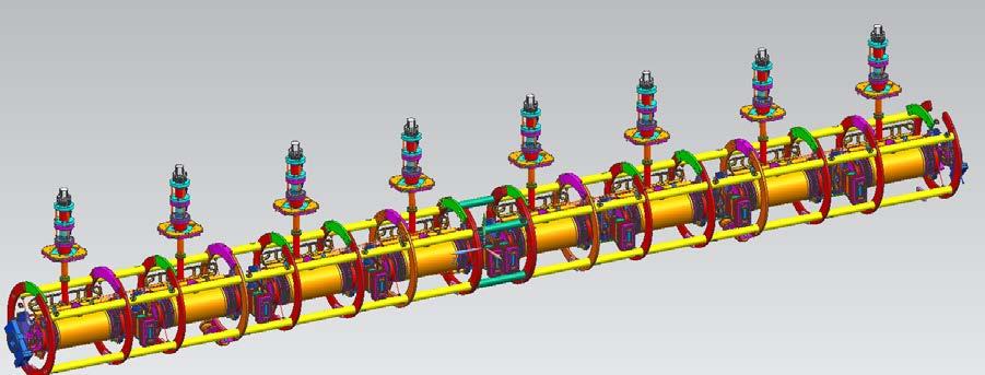
1 Microphonics T. Powers
2 What is microphonics? Microphonics is the time domain variation in cavity frequency driven by external vibrational sources. A 1.5 GHz structure 0.5 m long will change in frequency by `00 Hz if the length is changed 33 nm. It can be due to fixed frequency sources such as motors and equipment. When the source is white noise the results shows up as the natural vibrational frequencies or modes of the structure. We measure the microphonics on each series of cryomoudles and on a fraction of the cavities in the field. When we measured the first cryomodule installed in the machine we found larger than expected microphonics noise.
3 What is NOT microphonics? Static Lorentz force detuning Note: There are dynamic Lorentz force detuning effects that can effect the cavity frequency shifts in time scales consistent with vibrational modes of the cavities. Proper gradient regulation can be used to address this. Low frequency pressure drifts with periods on the order of minutes to hours. These can be addressed with your motor driven tuners.
4 The math. Ignoring control loop gain and coupler bandwidth limitations the steady state amplitude and phase controls needed for microphonics is given by: PP RRRR = ββ + 1 LL 4ββQQ LL rr QQ 2 EE + II 0 QQ LL rr QQ ccccccφφ 2 δδδδ BB + 2QQ LL EE + II ff 0 QQ LL rr QQ ssssssφφ BB 0 φφ RRRR = aaaaaaaaaaaa δδδδ 2QQ LL EE + II ff 0 QQ LL rr QQ ssssssφφ BB 0 EE + II 0 QQ LL rr QQ ccccccφφ BB


5 Modal Response Testing A warm cavity was instrumented with 9 triaxial accelerometers A series of warm impulse hammer response tests were performed on structures ranging from bare cavities to a fully assembled cryomodule. This data was used in combination with finite element analysis to improve the design.

6 Background Microphonics Testing Data taken using digital low level RF system operated in a fixed frequency mode at 1497 MHz The RF phase angles between the incident power and the cavity field probe readings were recorded at 1000 S/sec for 100 seconds. Phase angle and cavity loaded-q used to calculate the detune frequency 8 channels of data were acquired synchronously.

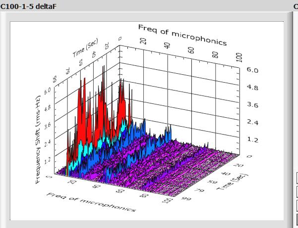
7 Microphonics Spectra as a function of Time


8 Time Domain Data for Cavities 1 to 4 and 5 to 8
 was higher than expected in first cryomodules A detailed")


9 Microphonics Design allows for 25 Hz Peak Detuning Microphonic Detuning* C100-1 C100-4 Actual peak detuning (21 Hz) was higher than expected in first cryomodules A detailed vibration study was initiating which led to the following design change. A minor change to the tuner pivot plate substantially improved the microphonics for the CEBAF C100 Cryomodules. RMS (Hz) σ(Hz) Cavity C Cavity C While both designs meet the overall system requirements the improved design has a larger RF power margin


10 Spectra with old and new tuner plates


11 Time Averaged Spectra Original Tuner Stiffened Tuner
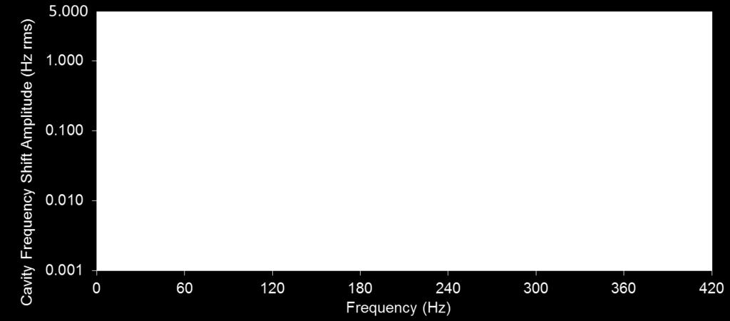
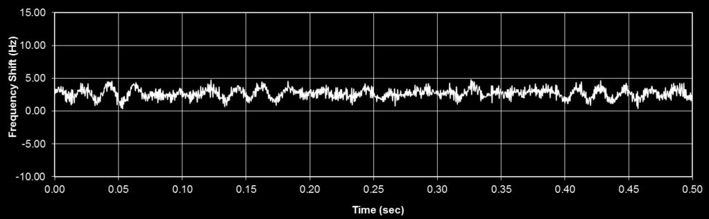
12 C50 Cryomodule Microphonics Time domain and frequency domain plots of the background microphonics for a 5-cell CEBAF cavity located in the CEBAF accelerator. Data taken in Tunnel

13 FEL3-6 Microphonics

14 FEL3-5 Tuner Running 2 steps/full step

15 FEL3-5 Tuner Operations 128 microsteps/step
 in cavity 5 Cavity 5 PZT moved 460 Hz.")

16 DYNAMIC COUPLING BETWEEN CAVITIES C100-4 Cavities 4, 6, 7, 8 responding to an applied PZT step control voltage change from 52 to 39 volts (130 Volt range) in cavity 5 Cavity 5 PZT moved 460 Hz. Locked in GDR Mode Because of 10 MV/m operating point, the klystron had the overhead to keep cavities locked Stepper Motor operated to tune the cavities Adjacent Cavity coupling is ~ 10% between 1-4 and 5-8 cavities Cavities 4 and 5 have a quasi mechanical support between them. Ringing is the 21 Hz mechanical Mode Curt Hovater, Tomasz Plawski,, Michael Wilson, Rama Bachimanchi
17 CRM EXAMPLES Freq Shift (Hz) Freq Shift (Hz) Cavity Frequency Shift (Hz) Piezo Drive Voltage (V) Time (s) Cavity Frequency Shift (Hz) Piezo Drive Voltage (V) Time (s) Step response of a cavity excited by a by a 50 Hz step in the piezo tuner controls. The total range of this tuner was 550 Hz PZT Drive (V) PZT Drive (V)
18 Q L General equation MinPower = Choosing Loaded-Q / δf ψ B 2 ( I ( r Q) cosψ ) + 2Q E + I ( r / Q) 0 B L 0 sin f0 E 2 For an ERL with perfect energy recovery. f0 QL MinPower 2Q δf L

19 Power Requirements As a Function of Loaded-Q 40 Hz detune allowance 20 Hz detune allowance MHz r/q = 525 Ω/m L = 1 m E = 12.5 MV/m
20 Required RF Power Including Margins As a function of Detune Allowance
21 The Math of Measuring Microphonics Neglecting coupler and control system bandwidths, etc. the RF power or voltage necessary to sustain steady state operation are given by the following equations. PP RRRR = ββ + 1 4ββββ LL RR QQ 2 VV CC + II oo QQ LL RR QQ ccccccφφ 2 δδδδ BB + 2QQ LL VV ff CC + II oo QQ LL RR QQ ssssssφφ BB 0 VV RRRR = ZZ 0 ββ + 1 4ββQQ LL RR/QQ VV CC 1 + iiiiiiiiφφ RRRR + II 0 QQ LL RR/QQ ccccccφφ BB + iiiiiiiiφφ BB Where φφ RRRR is the relative phase between the RF drive signal a signal (e.g. field probe signal) which is in phase and proportional to the cavity voltage. Thus as will be discussed later one can use the relative phase between the RF drive signal and the cavity field probe signal to calculate a relative value of δδδδ. Assuming that the beam current is zero this reduces to: VV RRRR = ZZ 0 ββ + 1 4ββQQ LL RR/QQ VV CC 1 + iiiqq LL δδδδ ff 0
22 Closed Loop RF Drive Requirements The bandwidth of the fundamental power coupler is given by the follow: BBBB = ff 0 QQ LL Equation (1) is the steady state equation that does not take into account the time domain nature of the beam loading or microphonics as well as the stored energy within the cavity. Ignoring the beam loading and stored energy effects and including the time domain microphonics effects this equation can be written as: VV RRRR = ZZ 0 ββ + 1 4ββQQ LL RR/QQ VV CC 1 + iiiqq LL δδδδ tt ff 0 It can be shown that any frequency dependence of δδδδ tt is maintained through the phase rotation and that both I an Q must be processed as part of the fundamental power coupler compensation.
23 Closed Loop Drive Requirements If one assumes that: δδδδ tt = ωω DD ssssss ωω mm tt And that the relative phase shift between the source and the cavity is zero then: VV RRRR = ZZ 0 ββ + 1 4ββQQ LL RR/QQ VV CC cccccc ωω 0 tt + 2QQ LL ωω DD ssssss ωω mm tt ff 0 ssssss ωω 0 tt Rewriting this in complex form: VV RRRR = ZZ 0 ββ + 1 4ββQQ LL RR/QQ VV CC 1 + jjjqq LL ωω DD ssssss ωω mm tt ff 0
24 Closed Loop Drive Requirements Looking at the closed loop control system block diagram: ff ββ, QQ LL VV IIIIII 1 + ωω BBBB Cavity Coupler VV RRRR VV CC Cavity VV FF VV RR VV DDDDDDDDDD LLRF VV FFFF What you are really measuring is VV IIIIII To understand what the cavity is actually doing you must apply a low pass filter to the I/Q data prior to processing. Conversely if one wants to understand the real RF power requirements one must model the system with the predicted microphonics and a cavity model that includes the coupler bandwidth.
25 Microphonics Measurements when using a frequency tracking source The goal is to come up with a way to calculate microphonics frequency from some basic RF measurement that is insensitive to magnitude. The equation for an RF signal that is frequency modulated at a frequency of ω m with a modulation depth (or frequency shift) of ω D and an RF frequency of ω m is given by: VV tt = VV PPPPPPPP CCCCCC ωω 0 tt + ωω 1 tt + ωω DD ωω mm ssssss ωω mm tt = VV PPPPPPPP CCCCCC ωω 0 tt + φφ tt In this method one uses the concept that an RF signal at a frequency of ωω 0 can be written in the form: VV = VV PPPPPPPP II tt cccccc ωω 0 tt + QQ tt ssssss ωω 0 tt Applying this to the above equation leads to: V tt = VV PPPPPPPP CCCCCC ωω 0 tt + φφ tt V tt = VV PPPPPPPP cccccc φφ tt cccccc ωω 0 tt VV PPPPPPPP ssssss φφ tt ssssss ωω 0 tt
26 Microphonics Measurements when using a frequency tracking source It can be shown that. QQ dddd dddd II dddd dddd = VV 2 dddd tt PPPPPPPP dddd OR 1 2 QQ dddd dddd 2ππVV PPPPPPPP II dddd dddd = ff tt Nominally VV PPPPPPPP is ½ the peak-to-peak value of the sine waveforms that are collected in the I and Q data stream, that is achieved when acquiring the data using a I/Q based receiver system. However, if the I/Q receiver happens to be very close ωω 0 + ωω 1 then I and Q will be DC or close to DC values (i.e. a full sine or cosine waveform is not collected in the data set. In this case one needs to calculate the magnitude of VV PPPPPPPP on a point by point basis as: 2 VV PPPPPPPP tt = II 2 tt + QQ 2 tt
27 Microphonics Measurements when using a frequency tracking source If one has a discrete data stream the general form of the frequency shift is given by: ff ii+1 = 1 2ππ QQ ii 2 + II ii 2 QQ ii II ii+1 II ii tt II ii QQ ii+1 QQ ii tt Which can be reduced to: ff ii+1 = QQ iiii ii+1 II ii QQ ii+1 2ππ tt QQ ii 2 + II ii 2 Another way to approach the problem is to look at just the I term in equation from two slides ago which is:
28 Microphonics Measurements when using a frequency tracking source Another way to approach the problem is to look at just the I term in equation from two slides ago which is: II tt = VV PPPPPPPP cccccc φφ tt = II 2 tt + QQ 2 tt cccccc φφ tt Solving for φφ tt φφ tt = cccccc 1 II tt II 2 tt + QQ 2 tt There is digital signal processing techniques known as a CORDIC algorithm [Lang, Antelo] which allows one to calculate the inverse cosine function efficiently. This would provide you with a sampled signal set of φφ tt. If this is done then one can calculate the frequency shift as. ff = φφ ii+1 φφ ii 2ππ tt One can also take the derivative of the inverse cosine function above and show that: ff ii+1 = QQ iiii ii+1 II ii QQ ii+1 2ππ tt QQ ii 2 + II ii 2

29 Approaches to Acquiring I/Q Data Stream There are two basic approaches to acquiring a digital I/Q data stream. In the first, called synchronous acquisition, the RF signal is down converted to an intermediate frequency and sampled at a frequency that is either 4, 1/1.25, 1/2.5, 1/5... times the nominal IF frequency. When this is done and the actual IF frequency the sampled points are as shown below: Sampled at 4 times the IF frequency Sampled at 1/1.25 times the IF frequency. Using this approach provides a data stream v 1, v 2, v 3,... and I and Q are given by: II kk = vv 4kk vv 4kk+2 aaaaaa QQ kk = vv 4kk+1 vv 4kk+3
30 Approaches to Acquiring I/Q Data Stream If the RF IF frequency is not precisely related to the sample frequency by the ratio 4, 1/1.25, 1/2.5, 1/5... the I and Q signals will have the form: II tt = VV PPPPPPPP cccccc ωω 1 tt + φφ tt QQ tt = VV PPPPPPPP ssssss ωω 1 tt + φφ tt Where ωω 1 is the difference frequency between the ideal IF frequency and the actual IF frequency. One can implement such a system using a simple mixer to down convert the RF signal to an IF frequency as shown below to collect the data. FREQUENCY TRACKING RF SOURCE FIXED FREQUENCY RF SOURCE Example Parameters: IF = 400 khz, ADC clock = 320 khz Filter BW = 200 khz RF LO IF BPF ADC_CLK ADC We will try this next week.
31 Approaches to Acquiring I/Q Data Stream If the RF IF frequency is not precisely related to the sample frequency by the ratio 4, 1/1.25, 1/2.5, 1/5... the I and Q signals will have the form: II tt = VV PPPPPPPP cccccc ωω 1 tt + φφ tt QQ tt = VV PPPPPPPP ssssss ωω 1 tt + φφ tt Where ωω 1 is the difference frequency between the ideal IF frequency and the actual IF frequency. One can implement such a system using a simple mixer to down convert the RF signal to an IF frequency as shown below to collect the data. FREQUENCY TRACKING RF SOURCE FIXED FREQUENCY RF SOURCE RF LO IF ADC_CLK ADC Example Parameters CEBAF 12 GeV Field Control Chassis: IF = 70 MHz, ADC clock = 56 MHz Filter BW = 5 MHz DSP filter bandwidths 30 khz variable BPF We will also use one of these next week.
32 Approaches to Acquiring I/Q Data Stream Alternately one can use an analog cavity resonance monitor. I II _ + dddd dddd dddd tt KK dddd VVVVVVVV ωω 0 tt + φφ tt 10 db 0 RF LO 3 db STABLE RF SOURCE khz LPF 1 Hz LPF LIMITER 90 RF LO I QQ _ dddd dddd + The front end circuitry requires careful tuning to ensure precise I/Q demodulation. The limiting amplifier is used to stabilize the gain in the system. Without it a separate power measurement would have to be made in order to calibrate the output signals. The analog baseband electronics provides the mathematical function of: QQ dddd dddd II dddd dddd
33 Application of Filters VV BBBBBBBBBBBBBBBB tt = VV PPPPPPPP CCCCCC ωω 1 tt + ωω DD ωω mm ssssss ωω mm tt This is the formula for an FM modulated signal. The solution has the form of Bessel functions. VV tt VV PPPPPPPP = cccccc ωω 1 tt JJ 0 mm kk JJ 2kk mm cccccc 2kkωω mm tt kk=1 +ssssss ωω 1 tt 2 1 kk JJ 2kk+1 mm cccccc 2kk + 1 ωω mm tt kk=0 Where: mm = ωω DD ωω mm
34 Example Spectra for FM Modulation Spectrum of I for(left) f D = 25 Hz, f M =10, f 1 =100 and M=2.5, (Right) f D = 25 Hz, f M =100, f 1 =100 and M=0.25. Spectrum of I for(left) f D = 200 Hz, f M =75, f 1 =100 and M=2.66, (Right) f D = 200 Hz, f M =75, f 1 =300 and M=2.66
 100 ks/s, (Top Right)10 ks/s, (Lower Left) 5 ks/s and (Lower Right)")
35 Effect of Sample Rate in Digitized System Time domain plot of the date from figure 3 sampled at (Top Left) 100 ks/s, (Top Right)10 ks/s, (Lower Left) 5 ks/s and (Lower Right) 2 ks/s
36 Lorentz Force Effect on Cavity Frequency as a Function of Gradient and for Different Instabilities in the Gradient with M=2
37 Impulse Response Test Math Excitation Excitation (hammer) Signal System Under Test Response Synchronous DAQ Signal Processing Transfer Function. H ω = avg Y ω avg X ω CCCCCCCCCCCCCCCCC. CC ωω = aaaaaa XX ωω XX ωω aaaaaa XX ωω YY ωω 2 aaaaaa YY ωω YY ωω
38 Math Transfer Function. Complex FFT is performed of the excitation and response signals. Because both real and imaginary information is included the transformed data contains all of the information in the original signal. The transfer function is calculated in the frequency domain and both phase and amplitude are plotted. Coherence Coherence is an indication that the system response is caused by the excitation. Coherence is calculated on a point by point basis in the frequency domain. Coherence is used to distinguish between responses that are driven by the excitation and the system response. If the system has vibrational characteristics that are driven by outside sources the coherence value will be less than one. Coherence REQUIRES averaging.
Low Level RF Systems
 Low Level RF Systems Tom Powers Jan. 2015 (Slides stolen from: Powers LLRF workshop 2011, Plawski LLRF workshop 2013, Power/Hovater LBL light source working group 2012, Powers, HOM workshop 2012. LLRF
Digital LLRF Test on the Renascence Cryomodule
 Digital LLRF Test on the Renascence Cryomodule Trent Allison, Rama Bachimanchi, Curt Hovater, John Musson and Tomasz Plawski Introduction The Renascence cryomodule was the first opportunity for testing
Cavity Testing Mathematics. Tom Powers USPAS SRF Testing Course 19 Jan. 2014
 Cavity Testing Mathematics Tom Powers USPAS SRF Testing Course 19 Jan. 014 General Block Diagram for Vertical or Horizontal Test Stand Frequency tracking source can be either a VCO-PLL based system or
C100 Cryomodule. Seven cell Cavity, 0.7 m long (high Q L ) 8 Cavities per Cryomodule Fits the existing Cryomodule footprint
 8 Cavities per Cryomodule Fits the existing Cryomodule footprint") 1 new module C100 Cryomodule Seven cell Cavity, 0.7 m long (high Q L ) 8 Cavities per Cryomodule Fits the existing Cryomodule footprint Fundamental frequency f 0 Accelerating gradient E acc 1497 MHz >
1 new module C100 Cryomodule Seven cell Cavity, 0.7 m long (high Q L ) 8 Cavities per Cryomodule Fits the existing Cryomodule footprint Fundamental frequency f 0 Accelerating gradient E acc 1497 MHz >
R.Bachimanchi, IPAC, May 2015, Richmond, VA
 1 new module C100 Cryomodule Seven cell Cavity, 0.7 m long (high Q L ) 8 Cavities per Cryomodule Fits the existing Cryomodule footprint Fundamental frequency f 0 Accelerating gradient E acc 1497 MHz >
ABSTRACT 1 CEBAF UPGRADE CAVITY/CRYOMODULE
 Energy Content (Normalized) SC Cavity Resonance Control System for the 12 GeV Upgrade Cavity: Requirements and Performance T. Plawski, T. Allison, R. Bachimanchi, D. Hardy, C. Hovater, Thomas Jefferson
Low-Level RF. S. Simrock, DESY. MAC mtg, May 05 Stefan Simrock DESY
 Low-Level RF S. Simrock, DESY Outline Scope of LLRF System Work Breakdown for XFEL LLRF Design for the VUV-FEL Cost, Personpower and Schedule RF Systems for XFEL RF Gun Injector 3rd harmonic cavity Main
Digital Low Level RF for SESAME
 Technical Sector Synchrotron-light for Experimental Science And Applications in the Middle East Subject : RF More specified area: Digital Low Level RF Date: 6/23/2010 Total Number of Pages: 11 Document
Digital Self Excited Loop Implementation and Experience. Trent Allison Curt Hovater John Musson Tomasz Plawski
 Digital Self Excited Loop Implementation and Experience Trent Allison Curt Hovater John Musson Tomasz Plawski Overview Why Self Excited Loop? Algorithm Building Blocks Hardware and Sampling Digital Signal
Borut Baricevic. Libera LLRF. 17 September 2009
 Borut Baricevic Libera LLRF borut.baricevic@i-tech.si 17 September 2009 Outline Libera LLRF introduction Libera LLRF system topology Signal processing structure GUI and signal acquisition RF system diagnostics
FLASH rf gun. beam generated within the (1.3 GHz) RF gun by a laser. filling time: typical 55 μs. flat top time: up to 800 μs
 RF gun by a laser. filling time: typical 55 μs. flat top time: up to 800 μs") The gun RF control at FLASH (and PITZ) Elmar Vogel in collaboration with Waldemar Koprek and Piotr Pucyk th FLASH Seminar at December 19 2006 FLASH rf gun beam generated within the (1.3 GHz) RF gun by
The gun RF control at FLASH (and PITZ) Elmar Vogel in collaboration with Waldemar Koprek and Piotr Pucyk th FLASH Seminar at December 19 2006 FLASH rf gun beam generated within the (1.3 GHz) RF gun by
Cavity Field Control - RF Field Controller. LLRF Lecture Part3.3 S. Simrock, Z. Geng DESY, Hamburg, Germany
 Cavity Field Control - RF Field Controller LLRF Lecture Part3.3 S. Simrock, Z. Geng DESY, Hamburg, Germany Content Introduction to the controller Control scheme selection In-phase and Quadrature (I/Q)
Direct Digital Down/Up Conversion for RF Control of Accelerating Cavities
 Direct Digital Down/Up Conversion for RF Control of Accelerating Cavities C. Hovater, T. Allison, R. Bachimanchi, J. Musson and T. Plawski Introduction As digital receiver technology has matured, direct
CDS 101/110: Lecture 8.2 PID Control
 CDS 11/11: Lecture 8.2 PID Control November 16, 216 Goals: Nyquist Example Introduce and review PID control. Show how to use loop shaping using PID to achieve a performance specification Discuss the use
Waveguide Arc Restrike Test Results Abstract Background
 Waveguide Arc Restrike Test Results Tom Powers, Doug Curry, Kirk Davis, Larry King, and Mike Tiefenback Thomas Jefferson National Accelerator Facility (Test dates July 6, 2004 through September 2, 2004)
ANGLE MODULATION. U1. PHASE AND FREQUENCY MODULATION For angle modulation, the modulated carrier is represented by
 [4.1] ANGLE MODULATION U1. PHASE AND FREQUENCY MODULATION For angle modulation, the modulated carrier is represented by xx cc (tt) = AA cccccc[ωω cc tt + φφ(tt)] (1.1) Where A ω c are constants the phase
Lab #2: Electrical Measurements II AC Circuits and Capacitors, Inductors, Oscillators and Filters
 Lab #2: Electrical Measurements II AC Circuits and Capacitors, Inductors, Oscillators and Filters Goal: In circuits with a time-varying voltage, the relationship between current and voltage is more complicated
Digital Logic, Algorithms, and Functions for the CEBAF Upgrade LLRF System Hai Dong, Curt Hovater, John Musson, and Tomasz Plawski
 Digital Logic, Algorithms, and Functions for the CEBAF Upgrade LLRF System Hai Dong, Curt Hovater, John Musson, and Tomasz Plawski Introduction: The CEBAF upgrade Low Level Radio Frequency (LLRF) control
Update 5/19/11. Kirk Davis, Mike Drury, Leigh Harwood, Mark Wiseman, etc. Andrew Hutton
 R100 Microphonics i Update 5/19/11 Andrew Hutton Reporting on work by Kirk Davis, Mike Drury, Leigh Harwood, John Hogan, Curt Hovater, Thomas Plawski, Mark Wiseman, etc. The Problem Vibrations of the superconducting
R100 Microphonics. Kirk Davis, Mike Drury, Leigh Harwood, Mark Wiseman, etc. Andrew Hutton
 R100 Microphonics Andrew Hutton Reporting on work by Kirk Davis, Mike Drury, Leigh Harwood, John Hogan, Kurt Hovater, Thomas Plawski, Mark Wiseman, etc. The Problem Vibrations of the superconducting cavities
Diode Circuits Recent GATE Problems
 Diode Circuits Recent GATE Problems 1. The diodes and capacitors in the circuit shown are ideal. The voltage v(t) across the diode DD 1 is CC 1 DD 2 cos(ωωωω) AC DD 1 CC 1 (a) cos(ωωωω) 1 (b) sin(ωωωω)
The low level radio frequency control system for DC-SRF. photo-injector at Peking University *
 The low level radio frequency control system for DC-SRF photo-injector at Peking University * WANG Fang( 王芳 ) 1) FENG Li-Wen( 冯立文 ) LIN Lin( 林林 ) HAO Jian-Kui( 郝建奎 ) Quan Sheng-Wen( 全胜文 ) ZHANG Bao-Cheng(
Theory and Practice of Cavity Test Systems. Tom Powers
 Theory and Practice of Cavity Test Systems Tom Powers SRF Workshop 2005 Tutorial Session INTRODUCTION Over the past 17 years we have done about 2500 cold cavity tests on more than 500 different cavities
Review on Progress in RF Control Systems. Cornell University. Matthias Liepe. M. Liepe, Cornell U. SRF 2005, July 14
 Review on Progress in RF Control Systems Matthias Liepe Cornell University 1 Why this Talk? As we all know, superconducting cavities have many nice features one of which is very high field stability. Why?
CDS 101/110: Lecture 9.1 Frequency DomainLoop Shaping
 CDS /: Lecture 9. Frequency DomainLoop Shaping November 3, 6 Goals: Review Basic Loop Shaping Concepts Work through example(s) Reading: Åström and Murray, Feedback Systems -e, Section.,.-.4,.6 I.e., we
EE3079 Experiment: Chaos in nonlinear systems
 EE3079 Experiment: Chaos in nonlinear systems Background: November 2, 2016 Revision The theory of nonlinear dynamical systems and Chaos is an intriguing area of mathematics that has received considerable
The performance of AM and FM receivers. Editor: Xuanfeng Li Teacher: Prof. Xiliang Luo
 The performance of AM and FM receivers Editor: Xuanfeng Li Teacher: Prof. Xiliang Luo The performance of AM receivers using Envelop Detection In a full AM signal, both sidebands and the carrier wave are
Studying Noise Contributions in Nonlinear Vector Network Analyzer (NVNA) Measurements
 Measurements") FACULTY OF ENGINEERING AND SUSTAINABLE DEVELOPMENT Studying Noise Contributions in Nonlinear Vector Network Analyzer (NVNA) Measurements Feng Tianyang September 2012 Master s Thesis in Telecommunications
FACULTY OF ENGINEERING AND SUSTAINABLE DEVELOPMENT Studying Noise Contributions in Nonlinear Vector Network Analyzer (NVNA) Measurements Feng Tianyang September 2012 Master s Thesis in Telecommunications
레이저의주파수안정화방법및그응용 박상언 ( 한국표준과학연구원, 길이시간센터 )
") 레이저의주파수안정화방법및그응용 박상언 ( 한국표준과학연구원, 길이시간센터 ) Contents Frequency references Frequency locking methods Basic principle of loop filter Example of lock box circuits Quantifying frequency stability Applications
레이저의주파수안정화방법및그응용 박상언 ( 한국표준과학연구원, 길이시간센터 ) Contents Frequency references Frequency locking methods Basic principle of loop filter Example of lock box circuits Quantifying frequency stability Applications
Slide Title. Bulleted Text
 Slide Title 1 Slide Outline Title Brief view of the C-AD Complex Review of the RHIC LLRF Upgrade Platform Generic Implementation of a Feedback Loop RHIC Bunch by Bunch Longitudinal Damper Cavity Controller
Homework Assignment Consider the circuit shown. Assume ideal op-amp behavior. Which statement below is true?
 Question 1 (2 points each unless noted otherwise) Homework Assignment 03 1. Consider the circuit shown. Assume ideal op-amp behavior. Which statement below is true? (a) V = VV + = 5 V (op-amp operation)
b) discrete-time iv) aperiodic (finite energy)
 discrete-time iv) aperiodic (finite energy)") EE 464 Frequency Analysis of Signals and Systems Fall 2018 Read Text, Chapter. Study suggestion: Use Matlab to plot several of the signals and their DTFT in the examples to follow. Some types of signal
EE 464 Frequency Analysis of Signals and Systems Fall 2018 Read Text, Chapter. Study suggestion: Use Matlab to plot several of the signals and their DTFT in the examples to follow. Some types of signal
EE-4022 Experiment 3 Frequency Modulation (FM)
") EE-4022 MILWAUKEE SCHOOL OF ENGINEERING 2015 Page 3-1 Student Objectives: EE-4022 Experiment 3 Frequency Modulation (FM) In this experiment the student will use laboratory modules including a Voltage-Controlled
EE-4022 MILWAUKEE SCHOOL OF ENGINEERING 2015 Page 3-1 Student Objectives: EE-4022 Experiment 3 Frequency Modulation (FM) In this experiment the student will use laboratory modules including a Voltage-Controlled
SNS LLRF Design Experience and its Possible Adoption for the ILC
 SNS LLRF Design Experience and its Possible Adoption for the ILC Brian Chase SNS - Mark Champion Fermilab International Linear Collider Workshop 11/28/2005 1 Why Consider the SNS System for ILC R&D at
Analysis and Comparison of Speed Control of DC Motor using Sliding Mode Control and Linear Quadratic Regulator
 ISSN: 2349-253 Analysis and Comparison of Speed Control of DC Motor using Sliding Mode Control and Linear Quadratic Regulator 1 Satyabrata Sahoo 2 Gayadhar Panda 1 (Asst. Professor, Department of Electrical
State of the Art in RF Control
 State of the Art in RF Control S. Simrock, DESY LINAC 2004, Lübeck Stefan Simrock DESY Outline RF System Architecture Requirements for RF Control RF Control Design Considerations Design Efforts Worldwide
Overview of ERL Projects: SRF Issues and Challenges. Matthias Liepe Cornell University
 Overview of ERL Projects: SRF Issues and Challenges Matthias Liepe Cornell University Overview of ERL projects: SRF issues and challenges Slide 1 Outline Introduction: SRF for ERLs What makes it special
Cavity Field Control - Feedback Performance and Stability Analysis. LLRF Lecture Part3.2 S. Simrock, Z. Geng DESY, Hamburg, Germany
 Cavity Field Control - Feedback Performance and Stability Analysis LLRF Lecture Part3.2 S. Simrock, Z. Geng DESY, Hamburg, Germany Motivation Understand how the perturbations and noises influence the feedback
Digital Signal Processing in RF Applications
 Digital Signal Processing in RF Applications Part II Thomas Schilcher Outline 1. signal conditioning / down conversion 2. detection of amp./phase by digital I/Q sampling I/Q sampling non I/Q sampling digital
EXPERIMENTAL RESULT OF LORENTZ DETUNING IN STF PHASE-1 AT KEK-STF
 EXPERIMENTAL RESULT OF LORENTZ DETUNING IN STF PHASE-1 AT KEK-STF Y. Yamamoto #, H. Hayano, E. Kako, T. Matsumoto, S. Michizono, T. Miura, S. Noguchi, M. Satoh, T. Shishidio, K. Watanabe, KEK, Tsukuba,
Energy Recovering Linac Issues
 Energy Recovering Linac Issues L. Merminga Jefferson Lab EIC Accelerator Workshop Brookhaven National Laboratory February 26-27, 2002 Outline Energy Recovery RF Stability in Recirculating, Energy Recovering
RF System Models and Longitudinal Beam Dynamics
 RF System Models and Longitudinal Beam Dynamics T. Mastoridis 1, P. Baudrenghien 1, J. Molendijk 1, C. Rivetta 2, J.D. Fox 2 1 BE-RF Group, CERN 2 AARD-Feedback and Dynamics Group, SLAC T. Mastoridis LLRF
Vibration studies of a superconducting accelerating
 Vibration studies of a superconducting accelerating module at room temperature and at 4.5 K Ramila Amirikas, Alessandro Bertolini, Wilhelm Bialowons Vibration studies on a Type III cryomodule at room temperature
Chapter 10. Quadrature Multiplexing and Frequency Division Multiplexing
 Chapter 10. Quadrature Multiplexing and Frequency Division Multiplexing 1 Goals Design a modulation and demodulation system for quadrature multiplexing (QM) amplitude modulation (AM). Design a frequency
Status of superconducting module development suitable for cw operation: ELBE cryostats
 Status of superconducting module development suitable for cw operation: ELBE cryostats, A. Büchner, H. Büttig, F. Gabriel, P. Michel, K. Möller, U. Lehnert, Ch. Schneider, J. Stephan, A. Winter Forschungszentrum
Superstructures; First Cold Test and Future Applications
 Superstructures; First Cold Test and Future Applications DESY: C. Albrecht, V. Ayvazyan, R. Bandelmann, T. Büttner, P. Castro, S. Choroba, J. Eschke, B. Faatz, A. Gössel, K. Honkavaara, B. Horst, J. Iversen,
Physics Requirements Document Document Title: SCRF 1.3 GHz Cryomodule Document Number: LCLSII-4.1-PR-0146-R0 Page 1 of 7
 Document Number: LCLSII-4.1-PR-0146-R0 Page 1 of 7 Document Approval: Originator: Tor Raubenheimer, Physics Support Lead Date Approved Approver: Marc Ross, Cryogenic System Manager Approver: Jose Chan,
Satellite Link Connection with C6M-II-SE
 3-8 Installation Satellite Link Connection with C6M-II-SE Figure 3-5 shows the connection between the C6R-VCII satellite receiver and the C6M-II with the Stereo Encoder option installed. Figure 3-5 Satellite
Modeling and Simulation of Load Frequency Control for Three Area Power System Using Proportional Integral Derivative (PID) Controller
 Controller") American Scientific Research Journal for Engineering, Technology, and Sciences (ASRJETS) ISSN (Print) 2313-441, ISSN (Online) 2313-442 Global Society of Scientific Research and Researchers http://asrjetsjournal.org/
American Scientific Research Journal for Engineering, Technology, and Sciences (ASRJETS) ISSN (Print) 2313-441, ISSN (Online) 2313-442 Global Society of Scientific Research and Researchers http://asrjetsjournal.org/
Project X Cavity RF and mechanical design. T. Khabiboulline, FNAL/TD/SRF
 Project X Cavity RF and mechanical design T. Khabiboulline, FNAL/TD/SRF TTC meeting on CW-SRF, 2013 Project X Cavity RF and mechanical design T 1 High ß Low ß 0.5 HWR SSR1 SSR2 0 1 10 100 1 10 3 1 10 4
MEMS Clocks: the next big little thing? Giorgio Mussi November 14 th, 2017
 MEMS Clocks: the next big little thing? Giorgio Mussi giorgio.mussi@polimi.it November 14 th, 2017 About me 2 Giorgio Mussi BSc+MSc in Electronics Engineering PhD with Prof. Langfelder I m in my 2 nd year
Theoretical 1 Bit A/D Converter
 Acquisition 16.1 Chapter 4 - Acquisition D/A converter (or DAC): Digital to Analog converters are used to map a finite number of values onto a physical output range (usually a ) A/D converter (or ADC):
UNIT-2 Angle Modulation System
 UNIT-2 Angle Modulation System Introduction There are three parameters of a carrier that may carry information: Amplitude Frequency Phase Frequency Modulation Power in an FM signal does not vary with modulation
RFID Systems: Radio Architecture
 RFID Systems: Radio Architecture 1 A discussion of radio architecture and RFID. What are the critical pieces? Familiarity with how radio and especially RFID radios are designed will allow you to make correct
note application Measurement of Frequency Stability and Phase Noise by David Owen
 application Measurement of Frequency Stability and Phase Noise note by David Owen The stability of an RF source is often a critical parameter for many applications. Performance varies considerably with
PXIe Contents SPECIFICATIONS. 14 GHz and 26.5 GHz Vector Signal Analyzer
 SPECIFICATIONS PXIe-5668 14 GHz and 26.5 GHz Vector Signal Analyzer These specifications apply to the PXIe-5668 (14 GHz) Vector Signal Analyzer and the PXIe-5668 (26.5 GHz) Vector Signal Analyzer with
Correction for Synchronization Errors in Dynamic Measurements
 Correction for Synchronization Errors in Dynamic Measurements Vasishta Ganguly and Tony L. Schmitz Department of Mechanical Engineering and Engineering Science University of North Carolina at Charlotte
Utilizzo del Time Domain per misure EMI
 Utilizzo del Time Domain per misure EMI Roberto Sacchi Measurement Expert Manager - Europe 7 Giugno 2017 Compliance EMI receiver requirements (CISPR 16-1-1 ) range 9 khz - 18 GHz: A normal +/- 2 db absolute
LCLS-II LLRF Prototype Testing and Characterization. Larry Doolittle, Brian Chase, Joshua Einstein-Curtis, Carlos Serrano LLRF 17,
 LCLS-II LLRF Prototype Testing and Characterization Larry Doolittle, Brian Chase, Joshua Einstein-Curtis, Carlos Serrano LLRF 17, 2017-10-16 Outline A little background on LCLS-II LLRF Design - DSP algorithms
Software Requirements Specification for LLRF Applications at FLASH Version 1.0 Prepared by Zheqiao Geng MSK, DESY Nov. 06, 2009
 Software Specification for LLRF Applications at FLASH Version 1.0 Prepared by Zheqiao Geng MSK, DESY Nov. 06, 2009 Copyright 2009 by Zheqiao Geng. Any change of this document should be agreed by the development
MIMO-LTI Feedback Controller Design -Status report-
 MIMO-LTI Feedback Controller Design -Status report- Christian Schmidt Deutsches Elektronen Synchrotron Technische Universitaet Hamburg Harburg FLASH Seminar 4/1/28 Outline Current RF Feedback System MIMO
Design & Implementation of the LLRF System for LCLS-II. Andy Benwell (SLAC Spokesperson) LLRF 2017 October 16, 2017
 LLRF 2017 October 16, 2017") Design & Implementation of the LLRF System for LCLS-II Andy Benwell (SLAC Spokesperson) LLRF 2017 October 16, 2017 Outline LCLS II LCLS II LLRF Requirements/Parameters LLRF Team LLRF Design Testing efforts
Design & Implementation of the LLRF System for LCLS-II Andy Benwell (SLAC Spokesperson) LLRF 2017 October 16, 2017 Outline LCLS II LCLS II LLRF Requirements/Parameters LLRF Team LLRF Design Testing efforts
University of Portland EE 271 Electrical Circuits Laboratory. Experiment: Inductors
 University of Portland EE 271 Electrical Circuits Laboratory Experiment: Inductors I. Objective The objective of this experiment is to verify the relationship between voltage and current in an inductor,
EET 223 RF COMMUNICATIONS LABORATORY EXPERIMENTS
 EET 223 RF COMMUNICATIONS LABORATORY EXPERIMENTS Experimental Goals A good technician needs to make accurate measurements, keep good records and know the proper usage and limitations of the instruments
Capacitive MEMS accelerometer for condition monitoring
 Capacitive MEMS accelerometer for condition monitoring Alessandra Di Pietro, Giuseppe Rotondo, Alessandro Faulisi. STMicroelectronics 1. Introduction Predictive maintenance (PdM) is a key component of
Initial ARGUS Measurement Results
 Initial ARGUS Measurement Results Grant Hampson October 8, Introduction This report illustrates some initial measurement results from the new ARGUS system []. Its main focus is on simple measurements of
The Phased Array Feed Receiver System : Linearity, Cross coupling and Image Rejection
 The Phased Array Feed Receiver System : Linearity, Cross coupling and Image Rejection D. Anish Roshi 1,2, Robert Simon 1, Steve White 1, William Shillue 2, Richard J. Fisher 2 1 National Radio Astronomy
Local Oscillator Phase Noise and its effect on Receiver Performance C. John Grebenkemper
 Watkins-Johnson Company Tech-notes Copyright 1981 Watkins-Johnson Company Vol. 8 No. 6 November/December 1981 Local Oscillator Phase Noise and its effect on Receiver Performance C. John Grebenkemper All
SECTION 4: TRANSMISSION LINES. ESE 470 Energy Distribution Systems
 SECTION 4: TRANSMISSION LINES ESE 470 Energy Distribution Systems 2 Introduction Transmission Lines 3 Transmission and distribution of electrical power occurs over metal cables Overhead AC or DC Underground
RF/IF Terminology and Specs
 RF/IF Terminology and Specs Contributors: Brad Brannon John Greichen Leo McHugh Eamon Nash Eberhard Brunner 1 Terminology LNA - Low-Noise Amplifier. A specialized amplifier to boost the very small received
Jean-Pierre Braun obtained the B.E. degree from the Ecole d'ingénieurs de Genève, Switzerland, in 1980; the M.E.M. degree from the University of
 Jean-Pierre Braun obtained the B.E. degree from the Ecole d'ingénieurs de Genève, Switzerland, in 1980; the M.E.M. degree from the University of Technology Sydney, Australia, in 1993; and the M.Eng.Sc.
Supplementary Figures
 1 Supplementary Figures a) f rep,1 Δf f rep,2 = f rep,1 +Δf RF Domain Optical Domain b) Aliasing region Supplementary Figure 1. Multi-heterdoyne beat note of two slightly shifted frequency combs. a Case
SC5307A/SC5308A 100 khz to 6 GHz RF Downconverter. Datasheet SignalCore, Inc.
 SC5307A/SC5308A 100 khz to 6 GHz RF Downconverter Datasheet 2017 SignalCore, Inc. support@signalcore.com P RODUCT S PECIFICATIONS Definition of Terms The following terms are used throughout this datasheet
Resonator System for the BEST 70MeV Cyclotron
 Resonator System for the BEST 70MeV Cyclotron 20 nd International Conference on Cyclotrons and their Applications Vancouver, Canada, September 16-20, 2013 Vasile Sabaiduc, Dipl. Eng. Accelerator Technology
Automatic Control Motion control Advanced control techniques
 Automatic Control Motion control Advanced control techniques (luca.bascetta@polimi.it) Politecnico di Milano Dipartimento di Elettronica, Informazione e Bioingegneria Motivations (I) 2 Besides the classical
Spectrum Analyzer Training
 Spectrum Analyzer Training Roberto Sacchi Application Engineer roberto_sacchi@agilent.com Page 1 Agenda Introduction Overview: What is Signal Analysis? What Measurements are available? Theory of Operation
Predictions of LER-HER limits
 Predictions of LER-HER limits PEP-II High Current Performance T. Mastorides, C. Rivetta, J.D. Fox, D. Van Winkle Accelerator Technology Research Div., SLAC 2e 34 Meeting, May 2, 27 Contents In this presentation
Response spectrum Time history Power Spectral Density, PSD
 A description is given of one way to implement an earthquake test where the test severities are specified by time histories. The test is done by using a biaxial computer aided servohydraulic test rig.
Accurate Power Conversion Measurements on High Power Motor Drives. Presented by: Ian Walker GMW Associates
 Accurate Power Conversion Measurements on High Power Motor Drives Presented by: Ian Walker GMW Associates ian@gmw.com Motor & Drive Systems; January 21, 2016 Interconnections for the test of a low power
EUROFEL-Report-2006-DS EUROPEAN FEL Design Study
 EUROFEL-Report-2006-DS3-034 EUROPEAN FEL Design Study Deliverable N : D 3.8 Deliverable Title: RF Amplitude and Phase Detector Task: Author: DS-3 F.Ludwig, M.Hoffmann, M.Felber, Contract N : 011935 P.Strzalkowski,
Analog and Telecommunication Electronics
 Politecnico di Torino Electronic Eng. Master Degree Analog and Telecommunication Electronics C5 - Synchronous demodulation» AM and FM demodulation» Coherent demodulation» Tone decoders AY 2015-16 19/03/2016-1
LORENTZ FORCE DETUNING ANALYSIS OF THE SPALLATION NEUTRON SOURCE (SNS) ACCELERATING CAVITIES *
 ACCELERATING CAVITIES *") LORENTZ FORCE DETUNING ANALYSIS OF THE SPALLATION NEUTRON SOURCE (SNS) ACCELERATING CAVITIES * R. Mitchell, K. Matsumoto, Los Alamos National Lab, Los Alamos, NM 87545, USA G. Ciovati, K. Davis, K. Macha,
LORENTZ FORCE DETUNING ANALYSIS OF THE SPALLATION NEUTRON SOURCE (SNS) ACCELERATING CAVITIES * R. Mitchell, K. Matsumoto, Los Alamos National Lab, Los Alamos, NM 87545, USA G. Ciovati, K. Davis, K. Macha,
LLRF Controls and Feedback: Free-Electron Lasers and Energy Recovery Linacs
 Proceedings of the CAS CERN Accelerator School: Free Electron Lasers and Energy Recovery Linacs, Hamburg, Germany, 31 May 10 June 2016, edited by R. Bailey, CERN Yellow Reports: School Proceedings, Vol.
Design and performance of LLRF system for CSNS/RCS *
 Design and performance of LLRF system for CSNS/RCS * LI Xiao 1) SUN Hong LONG Wei ZHAO Fa-Cheng ZHANG Chun-Lin Institute of High Energy Physics, Chinese Academy of Sciences, Beijing 100049, China Abstract:
 15-8 1/31/2014 PRELAB PROBLEMS 1. Why is the boundary condition of the cavity such that the component of the air displacement χ perpendicular to a wall must vanish at the wall? 2. Show that equation (5)
A new generation Cartesian loop transmitter for fl exible radio solutions
 Electronics Technical A new generation Cartesian loop transmitter for fl exible radio solutions by C.N. Wilson and J.M. Gibbins, Applied Technology, UK The concept software defined radio (SDR) is much
Effects of Intensity and Position Modulation On Switched Electrode Electronics Beam Position Monitor Systems at Jefferson Lab*
 JLAB-ACT--9 Effects of Intensity and Position Modulation On Switched Electrode Electronics Beam Position Monitor Systems at Jefferson Lab* Tom Powers Thomas Jefferson National Accelerator Facility Newport
National Accelerator Laboratory
 Fermi National Accelerator Laboratory FERMILAB-Conf-96/103 Trigger Delay Compensation for Beam Synchronous Sampling James Steimel Fermi National Accelerator Laboratory P.O. Box 500, Batavia, Illinois 60510
PHASE NOISE MEASUREMENT SYSTEMS
 PHASE NOISE MEASUREMENT SYSTEMS Item Type text; Proceedings Authors Lance, A. L.; Seal, W. D.; Labaar, F. Publisher International Foundation for Telemetering Journal International Telemetering Conference
ECE 421 Introduction to Signal Processing
 ECE 421 Introduction to Signal Processing Dror Baron Assistant Professor Dept. of Electrical and Computer Engr. North Carolina State University, NC, USA Digital Filter Design [Reading material: Chapter
INSTALLATION AND FIRST COMMISSIONING OF THE LLRF SYSTEM
 INSTALLATION AND FIRST COMMISSIONING OF THE LLRF SYSTEM FOR THE EUROPEAN XFEL Julien Branlard, for the LLRF team TALK OVERVIEW 2 Introduction Brief reminder about the XFEL LLRF system Commissioning goals
EE470 Electronic Communication Theory Exam II
 EE470 Electronic Communication Theory Exam II Open text, closed notes. For partial credit, you must show all formulas in symbolic form and you must work neatly!!! Date: November 6, 2013 Name: 1. [16%]
10th ESLS RF Meeting September ALBA RF System. F. Perez. on behalf of the ALBA RF Group. ALBA RF System 1/21
 ALBA RF System F. Perez on behalf of the ALBA RF Group ALBA RF System 1/21 Synchrotron Light Source in Cerdanyola (Barcelona, Spain) 3 GeV accelerator 30 beamlines (7 on day one) 50-50 Spanish Government
EE434 ASIC & Digital Systems
 EE434 ASIC & Digital Systems Partha Pande School of EECS Washington State University pande@eecs.wsu.edu Spring 2015 Dae Hyun Kim daehyun@eecs.wsu.edu 1 Lecture 4 More on CMOS Gates Ref: Textbook chapter
Lab 4. Crystal Oscillator
 Lab 4. Crystal Oscillator Modeling the Piezo Electric Quartz Crystal Most oscillators employed for RF and microwave applications use a resonator to set the frequency of oscillation. It is desirable to
Examination of Microphonic Effects in SRF Cavities
 Examination of Microphonic Effects in SRF Cavities Christina Leidel Department of Physics, Ohio Northern University, Ada, OH, 45810 (Dated: August 13, 2004) Superconducting RF cavities in Cornell s proposed
Real-Time Digital Down-Conversion with Equalization
 Real-Time Digital Down-Conversion with Equalization February 20, 2019 By Alexander Taratorin, Anatoli Stein, Valeriy Serebryanskiy and Lauri Viitas DOWN CONVERSION PRINCIPLE Down conversion is basic operation
Detection Probability of Harmonics in Power Systems Affected by Frequency Fluctuation
 Detection Probability of Harmonics in Power Systems Affected by Frequency Fluctuation Diego Bellan Abstract This paper deals with the derivation of detection probability of power system harmonics affected
Chapter 6: Power Amplifiers
 Chapter 6: Power Amplifiers Contents Class A Class B Class C Power Amplifiers Class A, B and C amplifiers are used in transmitters Tuned with a band width wide enough to pass all information sidebands
Simulating and Testing of Signal Processing Methods for Frequency Stepped Chirp Radar
 Test & Measurement Simulating and Testing of Signal Processing Methods for Frequency Stepped Chirp Radar Modern radar systems serve a broad range of commercial, civil, scientific and military applications.