nonlinearcircuits QUO/LPF build notes version 2 11 April 2014
|
|
|
- Nathan Burke
- 5 years ago
- Views:
Transcription
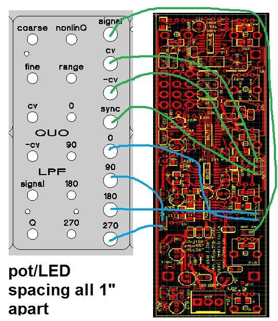
1 nonlinearcircuits QUO/LPF build notes version 2 11 April 2014 This circuit is based on the 4 pole LPF in Electronotes 41, tho has been subject to a number of tweaks and prods to bring it to where it is now. This manual is mainly intended for the Version 2 PCB, how do you know which version is which? Version 2 has V2.0 printed just near the Q pot and power connector. BOM components in bold indicate the value printed on PCB, but other values can be installed as noted component quantity 4 pole ON-ON toggle switch 1 select high or low range 100k pots 7 see notes Connector - Molex,.156 in KK, up, 3 1 pin TL074 2 SMT SOIC pitch NJM13700M 2 DMP16 package see notes J108 or J112 FET 4 marked gsd on PCB BC547 5 no mark, just transistor outline BC557 2 matched! marked p on PCB 150pF 4 4.5mm pin spacing, polys or something nice 1nF 4 5.0mm pin spacing, polys or something nice 10uF BP (25v or higher rating) 3 2.0mm pin spacing, must be bipolar 10uF (35v or higher rating) 2 2.5mm pin spacing, for decoupling sockets 8 nanas or whatever you choose 20k multi-turn trimpot 1 100k regular trimpot 1 1N optional, reverse voltage protection LEDs 4 3V zener diodes 2 up to 5V is probably okay 1N any regular signal diodes ok 47nF-100nF caps mm pin spacing, for decoupling, unmarked on PCB 20-30pF 1 2.5mm pin spacing, nF smd for decoupling thru-hole resistors 10R 2 220R 8 470R 4 for LED brightness, adjust to suit LED types 1k 4 2k2 1 10k 1 33k 7 51k 1 see notes, 100k - 120k is better 56k 1

2 91k 1 180k 1 220k 2 300k 1 3M 1 1k tempco 1 optional, only if using as VCO or care about 1V/oct, otherwise regular 1k okay 1206 smd resistors 10k 10 marked d on PCB, except for one marked 10 30k 4 100k 20 marked C on PCB 200k 1 see notes pots These ones from Tayda will do, though be careful none of the metal flaps are sitting on PCB traces, trim them back if so. You can find many brands of this type of pot, Alpha make nice ones too. 51k thru-hole and 200k 1206 smd resistors These two control the amplitude of the output signals. 51k sets the level for the and 0 0 outputs and 200k sets the level for the 90 0 and outputs. The 200k is probably fine, but the 51k should be increased as the corresponding levels are lower. Try 120k. This type of circuit is firstly a VCF; the QUO function is a bonus. It means the signals get smaller when the QUO is run very slowly, down to 2V p-p, at higher frequencies the QUO will be 10V p-p..or depending on what resistor values you choose to set the output signal levels. NJM13700M This is a wide-body package, not the standard SOIC. It is in production and available from Mouser, Digikey and RS components, about $1.20 each. 4 pole switch I used this


 to ensure the tempco is not in")
3 Tempco resistor and standoff The 1k tempco is place in contact with the matched PNP transistors. If you don t care about 1V/oct scaling, don t bother matching the transistors and use a regular 1k resistor. The module will still work perfectly well. One solder point for the 1k tempco is close to the stand-off mount and the leg of the resistor may touch the nut or screw of the standoff. I got around this by placing a plastic nut (a plastic washer will do too) to ensure the tempco is not in contact with the stand-off. If you use pots that bolt to the panel, you will not need stand-offs, so this section is not important See picture below:

4 Building I assume if you bought the PCB, you know what you are doing. If not, start with the surface mount parts first, then the chips. It will be very difficult to install the chips last, which is the usual procedure, so install them before getting the thru-hole parts on board. Once the SMD is done, carry on as usual, resistors, caps, trannies as you like. Setup The 20k multi trimpot is to get 1V/Oct scaling. Adjust the Coarse & Fine pots so your multi-meter reads 0V at the base of the PNP transistor connected to the 1k tempco. Now insert a 1V CV signal and adjust the 20k trimpot until you see 18mV at the base of the trannie. The 100k trimpot serves to remove DC offset on the signal. It is a bit redundant as the 10uF bipolar caps do that as well. Nevertheless, monitor the signal going into the Q pot (pin 1) and adjust the 100k trimpot until this is centred on 0V, you need an oscilloscope for this. If you do not have one, no drama, make sure it is about in the middle setting and relax. Use The NL (nonlinear) pot is best kept at 0 for normal use. It is most effective when using the module as a filter. Get a nice filter patch running and try adjusting the NL pot to see what happens.


5 To use the module as a QUO, turn up the Q pot to at least 7. If it is turned to 10, it will still oscillate but the waveforms will not be nice sine-waves. Actually it takes a bit of tweaking to get the sines spot on, usually somewhere around will do it. For most purposes, it is even preferable not to have perfect sine-waves; distorted waveshapes have harmonics. The sync input is a hard sync, very hard, feeding it gates turns off the oscillator which allows a burst function. It can of course be fed audio rate signals to modulate the filter. This vid is a good demo of this module in action -
6
7
Double Penetration (DP) Filter nonlinearcircuits
 Filter nonlinearcircuits") Double Penetration (DP) Filter nonlinearcircuits Build guide & BOM Vers.1 18/1/2014 Large schematic is here - http://www.sdiy.org/pinky/data/bipolar%20vcfs.pdf Module description - http://www.sdiy.org/pinky/data/bp.html
Double Penetration (DP) Filter nonlinearcircuits Build guide & BOM Vers.1 18/1/2014 Large schematic is here - http://www.sdiy.org/pinky/data/bipolar%20vcfs.pdf Module description - http://www.sdiy.org/pinky/data/bp.html
build info nonlinearcircuits
 It s 555 resonator build info nonlinearcircuits BOM BC547 10 npn marked n on PCB see notes BC557 10 pnp- marked p on PCB see notes 555 IC 5 TL072 2 TL074 1 power connector 0.156 1 Molex 3 pin 100k pots
nonlinearcircuits NULL-A 2 Build & BOM
 nonlinearcircuits NULL-A 2 Build & BOM Null-A 2 is an all-in-one analogue synth packed into 42HP. It features: 2 VCOs 1 state variable VCF 1 ladder VCF 1 VC Delay 3 VCAs 2 LFOs Mixer Headphone amp Sequencer
J HAIBLE DUAL WASP VCF (Euro)
") J HAIBLE DUAL WASP VCF (Euro) Jürgen Haible s WASP Filter adaption of the famous CMOS VCF introduced some unique features, in particular a distortion stage. The R*S version takes this a step further by
J HAIBLE DUAL WASP VCF (Euro) Jürgen Haible s WASP Filter adaption of the famous CMOS VCF introduced some unique features, in particular a distortion stage. The R*S version takes this a step further by
AMSynths AM8044 VCF & VCA. Project Notes V2.0
 AMSynths AM8044 VCF & VCA Project Notes V2.0 AMSynths 2013 Rob Keeble Contact: sales@amsynths.co.uk Web Site: www.amsynths.co.uk 18 May 2013 1 Module Description This module is designed around the SSM2044
The Tellun Corporation. TLN-442 Voltage Controlled Lowpass Filter. User Guide, Rev Scott Juskiw The Tellun Corporation
 The Tellun Corporation TLN-442 Voltage Controlled Lowpass Filter User Guide, Rev. 1.1 Scott Juskiw The Tellun Corporation scott@tellun.com TLN-442 User Guide Revision 1.1 March 15, 2003 Introduction The
TLN-428 Voltage Controlled State Variable Filter
 The Tellun Corporation TLN-428 Voltage Controlled State Variable Filter User Guide, Rev. 1.1 Scott Juskiw The Tellun Corporation scott@tellun.com TLN-428 User Guide Revision 1.1 March 16, 2003 Introduction
SERGE Ring Modulator 2017 (RING) for Eurorack
 for Eurorack") SERGE Ring Modulator 2017 (RING) for Eurorack The 2017 RING is an improved version of the late Serge Ring Modulator (R9), designed by Serge himself for Random*Source in 2017, more than 40 years after the
SERGE Ring Modulator 2017 (RING) for Eurorack The 2017 RING is an improved version of the late Serge Ring Modulator (R9), designed by Serge himself for Random*Source in 2017, more than 40 years after the
Introduction. State Variable VCF 12dB/Octave With VC Resonance (+/-9V to +/-15V)
") State Variable VCF 12dB/Octave With VC Resonance (+/-9V to +/-15V) Article by Ray Wilson This is an intermediate to advanced project and I do not recommend it as a first project if you are just getting
State Variable VCF 12dB/Octave With VC Resonance (+/-9V to +/-15V) Article by Ray Wilson This is an intermediate to advanced project and I do not recommend it as a first project if you are just getting
DIY Function Generator XR2206
 DIY Function Generator XR2206 20Hz 100KHz http://radiohobbystore.com Components List: Resistors: R1, R2 1% Metal Film 5K1 R4 1% Metal Film 10K R5 1% Metal Film 3K R10 5% Carbon Film 10R R3, R9 Potentiometer
Dual Digital Build Manual
 Dual Digital Build Manual Introduction This document is meant to aid you in assembling your Dual Digital Oscillator (DDO from now on). Some instructions may be a bit basic for advanced builders but I hope
AMSynths. AM8040 Voltage Controlled Low Pass Filter. Project Notes V2.2
 AMSynths AM8040 Voltage Controlled Low Pass Filter Project Notes V2.2 AMSynths 2013 Rob Keeble Contact: sales@amsynths.co.uk Web Site: www.amsynths.co.uk 29 June 2013 1 Module Description This module is
Blue jacks are inputs Red jacks are outputs Red wire +12V, Black wire 0V, Green wire -12V
 : Blue jacks are inputs Red jacks are outputs Red wire +12V, Black wire 0V, Green wire -12V This is a set of five 555 based one shot circuits. Each has CV and pot controlled pulse width and the pulse for
SERGE New Timbral Oscillator (NTO) for Eurorack
 for Eurorack") SERGE New Timbral Oscillator (NTO) for Eurorack The Serge NTO is an iconic Serge design and one of the rarest, most sought-after oscillators. To quote the original 1983 Serge catalog: The Serge New Timbral
SERGE New Timbral Oscillator (NTO) for Eurorack The Serge NTO is an iconic Serge design and one of the rarest, most sought-after oscillators. To quote the original 1983 Serge catalog: The Serge New Timbral
R*S Stereo Mixer V1.2
 R*S Stereo Mixer V1.2 The Random*Source Equal Power Stereo-Mixer is a voltage controlled stereo mixer / panner / VCA based on 4 high-end THAT2180 blackmer VCAs, designed to emulate the behavior of Serge
Version; first draft august 2018 Second draft september 2018, added schematic and adapted text to schematic
 Tuning the AS3340 Version; first draft august 2018 Second draft september 2018, added schematic and adapted text to schematic Author: Rob Hordijk (c)2018 Final draft to be released in the public domain.
Penrose Quantizer Assembly Guide
 Penrose Quantizer Assembly Guide Schematic and BOM The schematic can be found here: www.sonic-potions.com/public/penrosequantizerschematic.pdf The BOM is available at google docs: Link to BOM Prepare the
Eurorack DIY Kit Instructions. All Thonk kits are sold under our standard Terms and Conditions -
 MA VCA OVERVIEW For the most recent version of this document please visit http://thonk.co.uk/documents/ma/ For all technical support please visit http://bit.ly/1tl78e0 on Muffwiggler. All Thonk kits are
BassAce - Midi Bass Synthesizer. BassAce Features
 Untitled Document BassAce - Midi Bass Synthesizer The BassAce is a small midi-synth based loosely on the TB303. It can be built many different ways. Depending on how it's configured it can be anything
Workshop Part Identification Lecture N I A G A R A C O L L E G E T E C H N O L O G Y D E P T.
 Workshop Part Identification Lecture N I A G A R A C O L L E G E T E C H N O L O G Y D E P T. Identifying Resistors Resistors can be either fixed or variable. The variable kind are called potentiometers
LAYOUTS. Thomas Henry SSM2164 VCF/VCA v1. Adapter PCB top view (Panel side) Main PCB. Adapter PCB bottom view. 9/13/2016
 Main PCB. Adapter PCB bottom view. 9/13/2016") Thomas Henry SSM VCF/VCA v LAYOUTS The PCB/Panel combo is comprised of one main PCB, an adapter PCB, and an Eurorack format panel. Nevertheless, one can always use just the main PCB to build a module in
Thomas Henry SSM VCF/VCA v LAYOUTS The PCB/Panel combo is comprised of one main PCB, an adapter PCB, and an Eurorack format panel. Nevertheless, one can always use just the main PCB to build a module in
the DON classics U76 (blue face - rev A) ASSEMBLY GUIDE REV: 1:04
 ASSEMBLY GUIDE REV: 1:04") the DON classics www.thedonclassics.com U76 (blue face - rev A) ASSEMBLY GUIDE REV: 1:04 QUICK ASSEMBLY GUIDE 9 STEPS TO COMPRESSOR HEAVEN! 1. 2. 3. 4. 5. 6. 7. 8. 9. Solder parts on PCB Wire pots Solder
the DON classics www.thedonclassics.com U76 (blue face - rev A) ASSEMBLY GUIDE REV: 1:04 QUICK ASSEMBLY GUIDE 9 STEPS TO COMPRESSOR HEAVEN! 1. 2. 3. 4. 5. 6. 7. 8. 9. Solder parts on PCB Wire pots Solder
User Guide V
 XV User Guide V1.10 25-02-2017 Diode Ladder Wave Filter Thank you for purchasing the AJH Synth Sonic XV Eurorack synthesiser module, which like all AJH Synth products, has been designed and handbuilt in
Pingable Envelope Generator
 Pingable Envelope Generator Kit Builder's Guide for PCB v1.0.3 4mspedals.com PEG This guide is for building a Pingable Envelope Generator (PEG), which is an intermediate-level kit. You should be confident
R*S Stereo Mixer V1.3
 R*S Stereo Mixer V1.3 The Random*Source Equal Power Stereo-Mixer is a voltage controlled stereo mixer / panner / VCA based on 4 high-end THAT2180 blackmer VCAs, designed to emulate the behavior of Serge
Foxhunt Offset Attenuator. Parts List:
 When your closing in on the fox you may find the signals to be so strong that you can no longer find a peak or null with your antenna. Sometimes the signal is so strong that the RF will leak straight into
BMC052. Chordizer Last updated
 BMC052. Chordizer Last updated 8-27-2017 If you have any questions, or need help trouble shooting, please e-mail Michael@Bartonmusicalcircuits.com I Overview/Controls/Inputs/Outputs II Schematic III Construction
Analog Synthesizer: Functional Description
 Analog Synthesizer: Functional Description Documentation and Technical Information Nolan Lem (2013) Abstract This analog audio synthesizer consists of a keyboard controller paired with several modules
FM RADIO KIT ESSENTIAL INFORMATION. Version 2.0 GET IN TUNE WITH THIS
 ESSENTIAL INFORMATION BUILD INSTRUCTIONS CHECKING YOUR PCB & FAULT-FINDING MECHANICAL DETAILS HOW THE KIT WORKS GET IN TUNE WITH THIS FM RADIO KIT Version 2.0 Build Instructions Before you start, take
TS500 Assembly guide. Soldering. TS500 Assembly guide Main PCB 1. Diodes. Document revision 1.2 Last modification : 17/12/16
 TS500 Assembly guide Safety warning The kits are main powered and use potentially lethal voltages. Under no circumstance should someone undertake the realisation of a kit unless he has full knowledge about
4-Pole Mission filter board
 4-Pole Mission filter board One board to rule them all This filter board is probably the most advanced 4-pole core for the Shruthi-system! It uses the same Pole-mixing technique introduced in the Oberheim
SERGE Wave Multipliers (VCM)
") SERGE Wave Multipliers (VCM) The legendary Serge Wave Multipliers (VCM) are a module - or rather 3 modules - designed to dynamically add new harmonically-related overtones to an input waveform. Accroding
SERGE Wave Multipliers (VCM) The legendary Serge Wave Multipliers (VCM) are a module - or rather 3 modules - designed to dynamically add new harmonically-related overtones to an input waveform. Accroding
Multi-Window Comparator documentation. Written November 15, 2012 Last edited November 15, 2012
 Multi-Window Comparator documentation. Written November 15, 2012 Last edited November 15, 2012 I. What is a Multi-Window Comparator? A. A "regular" window comparator is this. B. A Multi-Window Comparator
The Tellun Corporation. TLN-863 Max Min Generator. User Guide, Rev Scott Juskiw The Tellun Corporation
 The Tellun Corporation TLN-863 Max Min Generator User Guide, Rev. 1.1 Scott Juskiw The Tellun Corporation scott@tellun.com TLN-863 User Guide Revision 1.1 May 26, 2008 1. Introduction The TLN-863 Max Min
Electric Druid Flangelicious Flanger Project
 Electric Druid Flangelicious Flanger Project (Using either 4KNOBFLANGE or MULTIFLANGE chips) Overview! 2 Build Instructions! 2 Populate the PCB! 2 1N4148 Diodes! 2 Resistors! 2 Cup of tea and soldering
BMC055. Sallen-Key Voltage Controlled Filter Last updated
 BMC055. Sallen-Key Voltage Controlled Filter Last updated 0-6-208 If you have any questions, or need help trouble shooting, please e-mail Michael@Bartonmusicalcircuits.com I What The Knobs And Jacks Do
Multiwave. Guitar Synthesizer. Build Document last updated november 2018 Version
 Multiwave Guitar Synthesizer Build Document last updated november 2018 Version 1.0 2018 The Multiwave is a guitar controlled oscillator with 3 different waveshapes: saw, triangle and square. Combined,
BYOC Vibrato Kit Instructions BA6110 version
 BYOC Vibrato Kit Instructions BA6110 version Please read these instructions very thoroughly before building even if you are an experience builder. Because of the
WHISTLE ROCK AUDIO ML12 PSU KIT/PCB
 WHISTLE ROCK AUDIO ML12 PSU KIT/PCB TABLE OF CONTENTS 1. INTRODUCTION Page 3 2. BILL OF MATERIAL Page 4 3. ALTERNATE RESISTOR VALUES Page 5 4. ASSEMBLY GUIDE Page 6 to 11 5. CONNECTIONS Page 12 6. SETUP
LITTLE NERD v1.1 Assembly Guide
 last update: 9. 3. 2016 LITTLE NERD v1.1 Assembly Guide bastl instruments.com INTRODUCTION This guide is for building Little Nerd module from Bastl Instruments. It is good to have basic soldering skills
Classic VCA. Builder's Guide. Oakley Sound Systems. 5U Oakley Modular Series. Discrete VCA PCB Issue 1 V1.0.1
 Oakley Sound Systems 5U Oakley Modular Series Classic VCA Discrete VCA PCB Issue 1 Builder's Guide V1.0.1 Tony Allgood Oakley Sound Systems CARLISLE United Kingdom Introduction This is the Project Builder's
BYOC Vibrato Kit Instructions BA662A version
 BYOC Vibrato Kit Instructions BA662A version Please read these instructions very thoroughly before building even if you are an experience builder. Because of the layout, there is a certain order which
5U Oakley Modular Series
 Oakley Sound Systems 5U Oakley Modular Series VC-LFO Low Frequency Oscillator PCB Issue 2 Builder s Guide V2.0.05 Tony Allgood B.Eng PGCE Oakley Sound Systems CARLISLE United Kingdom The suggested panel
HAMTRONICS TB901 FM EXCITER INSTALLATION, OPERATION, & MAINTENANCE
 HAMTRONICS TB901 FM EXCITER INSTALLATION, OPERATION, & MAINTENANCE GENERAL INFORMATION. The TB901 is a single-channel low power fm transmitter (exciter) designed to provide 300-600 milliwatts continuous
ABC V1.0 ASSEMBLY IMPORTANT!
 ABC V1.0 ASSEMBLY Before starting this kit, prepare the following tools: Soldering iron (15-20W will do), flush cutters, no.2 hex screwdriver or allen key and phillips screwdriver. Also briefly go through
BMC016. Dual Nice Quantizer. Last updated new calibration instructions
 BMC016. Dual Nice Quantizer. Last updated 8-19-2018 new calibration instructions There are two versions of this PCB, if you have a PCB with six trimpots, read THIS DOCUMENTATION instead. I Using The Dual
Construction notes for the symmetrical 400 watt amplifier
 Construction notes for the symmetrical 400 watt amplifier Introduction The symmetrical amplifier is an update of one of my designs, which appeared in the Australian electronics magazine Silicon Chip in
Through-Zero VoltageControlled Oscillator
 Through-Zero VoltageControlled Oscillator Liivatera OÜ Rävala pst. 8, A211 10143 Tallinn Harjumaa Estonia T: +372 637 6441 T: +44 5603 010854 E: contact@liivatera.com Through- Zero VCO Manual 0.1 1 Contents
NEW WAVE CV GENERATOR Build Document last updated september 2017 for PCB version 1.0
 NEW WAVE CV GENERATOR Build Document last updated september 2017 for PCB version 1.0 The New Wave is a Control Voltage Generator. It has two LFO's (low frequency oscillators) and four different output
HF Amateur SSB Receiver
 HF Amateur SSB Receiver PCB Set for radio club project http://rhelectronics.net PCB for DIY HF Amateur SSB Receiver 20M The receiver is a simple syperheterodyne type with quartz crystal filter. The circuit
Bi-Directional DC Motor Speed Controller 5-32Vdc (3166v2)
") General Guidelines for Electronic Kits and Assembled Modules Thank you for choosing one of our products. Please take some time to carefully read the important information below concerning use of this product.
General Guidelines for Electronic Kits and Assembled Modules Thank you for choosing one of our products. Please take some time to carefully read the important information below concerning use of this product.
Instruction Manual. SSQ-2F Controller Board. For the. v1.41 For Rife Plasma Tube Systems. Manual v by Ralph Hartwell Spectrotek Services
 Instruction Manual For the SSQ-2F Controller Board v1.41 For Rife Plasma Tube Systems Manual v1.00 2012 by Ralph Hartwell Spectrotek Services This page intentionally blank. 2 Index and Table of Contents
SUPER-ENHANCED POLIVOKS VCA DIY KIT ASSEMBLY INSTRUCTIONS
 SUPER-ENHANCED POLIVOKS VCA DIY KIT ASSEMBLY INSTRUCTIONS IF YOU ARE READING THIS, MOST PROBABLY YOU ARE ABOUT TO BUILD ERICA SYNTHS SUPER-ENHANCED POLIVOKS VCA. The Polivoks VCA has distinctive architecture
Dev Bhoomi Institute Of Technology Department of Electronics and Communication Engineering PRACTICAL INSTRUCTION SHEET
 Dev Bhoomi Institute Of Technology Department of Electronics and Communication Engineering PRACTICAL INSTRUCTION SHEET LABORATORY MANUAL EXPERIMENT NO. ISSUE NO. : ISSUE DATE: REV. NO. : REV. DATE : PAGE:
Jour de FET Mounting instructions.
 Jour de FET Mounting instructions. Summary Important notice. What's in the kit? What you'll need. Soldering on the pcb. Wiring the pedal. Test the board. Debugging chapter. Hacks!!! 3 4 4 3 5 6 Copyright
SoftRock v6.0 Builder s Notes. May 22, 2006
 SoftRock v6.0 Builder s Notes May 22, 2006 Be sure to use a grounded tip soldering iron in building the v6.0 SoftRock circuit board. The soldering iron needs to have a small tip, (0.05-0.1 inch diameter),
The Tellun Corporation. TLN-861 Dunsel. User Guide, Rev Scott Juskiw The Tellun Corporation
 The Tellun Corporation TLN-861 Dunsel User Guide, Rev. 1.0 Scott Juskiw The Tellun Corporation scott@tellun.com TLN-861 User Guide Revision 1.0 August 31, 2006 1. Introduction The TLN-861 Dunsel is a collection
G6ALU 20W FET PA Construction Information
 G6ALU 20W FET PA Construction Information The requirement This amplifier was designed specifically to complement the Pic-A-Star transceiver developed by Peter Rhodes G3XJP. From the band pass filter an
EFM electronics for music. EFM 4600 Series. Febuary 2007
 EFM 4600 Series Febuary 2007 500 series 544 High stability, high scale saw tri pulse sine VCO 4600 series 4602 /- 2V Regulated Power Supply 464 Low Parts count, high quality VCO 462 OB Sem Type 2P LP/HP/BP/Notch
EZ1290 Assembly Guide
 EZ190 Assembly Guide Capacitors This picture shows the different types of capacitors used and how they are symbolized and mounted on the PCB. Don t mess this up or bad things will happen!!! Electrolytic
// K3020 // Dual VCO. User Manual. Hardware Version E October 26, 2010 Kilpatrick Audio
 // K3020 // Dual VCO Kilpatrick Audio // K3020 // Dual VCO 2p Introduction The K3200 Dual VCO is a state-of-the-art dual analog voltage controlled oscillator that is both musically and technically superb.
Auto-Seq Documentation Written April 6th, 2014
 Auto-Seq Documentation Written April 6th, 2014 I. Using The Module A. What is Auto-Seq? B. Controls/Inputs/Outputs C. Sample Patches II. Schematics A.Chip Pinout B.Inputs 1.Analog Inputs 2.Digital Inputs
M328 version ESR inductance capacitance meter multifunctional tester DIY
 M328 version ESR inductance capacitance meter multifunctional tester DIY About transistor Multifunction Tester: The tester uses 3.7V rechargeable lithium battery (battery model: 14500) powered portable
BMC011. Wave Animator Written April 8, 2013 Last Editted April 8, 2013
 BMC011. Wave Animator Written April 8, 2013 Last Editted April 8, 2013 I. What is a Wave Animator?/Demos II. Circuit Description/Schematics III. Construction A. Parts List B. PCB Information I.What Is
A3930 and A3931. Demo Board Schematic/Layout SCHEMATIC A DB
 SCHEMATIC A3930-31-DB LAYOUT 2 3 4 BILL OF MATERIALS A3930/ Demo Board Rev 3 Component List Last Updated: 15/07/2014 Part Value Package Description RS Part Part Value Package Description RS Part C1 1000uF
Simple LFO Features. 2. Application. 3. Description. Simple and easy to build LFO module for Analog Synthesizers.
 Simple LFO. Simple and easy to build LFO module for Analog Synthesizers.. Features Square and Triangle waveforms (90 phase shifted) Dual range frequencies Frequency ranges from under Hz up to several khz
THE GREEN CURRANT TREMOLO Build Document last updated june 2017 for PCB version 1.5
 THE GREEN CURRANT TREMOLO Build Document last updated june 2017 for PCB version 1.5 The Green Currant tremolo is a very percussive and vibey tremolo based around the TDA7052A amplifier chip. It splits
ATV Modulator User Manual
 ATV Modulator User Manual FMTV Modulator by Grant ZL1WTT & Keith ZL1BQE 20 February 2004 Page 1 Display board layout The controller consists of a 2x 16 LCD display with three push buttons and a rotary
Starving Student II. Starving Student II. SS2 guide. Written By: 6L guides.diyaudio.com/ Page 1 of 24
 SS2 guide Written By: 6L6 2019 guides.diyaudio.com/ Page 1 of 24 INTRODUCTION This is a build guide for the hybrid headphone/pre-amplifier. You can buy a kit at the SSII product listing on the diyaudio
5U Oakley Modular Series. Dual Comparator and Gate Delay CV and Audio Processor
 Oakley Sound Systems 5U Oakley Modular Series Dual Comparator and Gate Delay CV and Audio Processor PCB Issue 2 Builder s Guide V2.1 Tony Allgood Oakley Sound Systems CARLISLE United Kingdom The suggested
A GOOD REGENERATIVE RECEIVER WITH SIMPLE FINE TUNING (2008)
") A GOOD REGENERATIVE RECEIVER WITH SIMPLE FINE TUNING (2008) A good SSB-CW-AM regenerative receiver with a fine tuning by moving the wooden stick with a grounded piece of PCB towards the coil. A good regenerative
A GOOD REGENERATIVE RECEIVER WITH SIMPLE FINE TUNING (2008) A good SSB-CW-AM regenerative receiver with a fine tuning by moving the wooden stick with a grounded piece of PCB towards the coil. A good regenerative
6. HARDWARE PROTOTYPE AND EXPERIMENTAL RESULTS
 6. HARDWARE PROTOTYPE AND EXPERIMENTAL RESULTS Laboratory based hardware prototype is developed for the z-source inverter based conversion set up in line with control system designed, simulated and discussed
BMC018. Analog Drum. Last updated
 BMC018. Analog Drum. Last updated 11-26-2013 I Features II Schematics A.Master Schematic. B.Input/Decay C.VCO D.VCA E.Power Connections. III Construction A.Parts List B.The Board I. Features This module
Build Guide CascadiA. GeFet Preamp
 Build Guide CascadiA GeFet Preamp Disclaimery stuff: This project is meant to be assembled by fellow DIYers from the Madbean forum and should only be used for the forces of good. Any other uses prohibited
Q107/Q107A State Variable Filter
 Apr 28, 2017 The Q107 is dual-wide, full-featured State Variable filter. The Q107A is a single-wide version without the Notch output and input mixer attenuator. These two models share the same circuit
LA502 Assembly guide Main PCB Resistors - (2)
") LA502 Assembly guide Safety warning The kits are main powered and use potentially lethal voltages. Under no circumstance should someone undertake the realisation of a kit unless he has full knowledge about
LA502 Assembly guide Safety warning The kits are main powered and use potentially lethal voltages. Under no circumstance should someone undertake the realisation of a kit unless he has full knowledge about
Arizona ScQRPion QRP Club. Ft Tuthill w DC CW Transceiver for 80m Part 1 of 2. by Dan Tayloe, N7VE. Ft Tuthill Page 1 of 31
 Arizona ScQRPion QRP Club Ft Tuthill 80 2.5w DC CW Transceiver for 80m Part 1 of 2 by Dan Tayloe, N7VE Page 1 of 31 Table of Contents Specifications... 4 Specifications... 4 Receiver... 4 Transmitter...
CV Arpeggiator Rev 1. Last updated
 CV Arpeggiator Rev Last updated 6--20 The CV Arpeggiator is a modular synth project used for creating arpeggios of control voltage. It utilizes a custom programmed PIC 6F685 micro controller. It includes
SoftRock v6.0 Builder s Notes. April 6, 2006
 SoftRock v6.0 Builder s Notes April 6, 006 Be sure to use a grounded tip soldering iron in building the v6.0 SoftRock circuit board. The soldering iron needs to have a small tip, (0.05-0. inch diameter),
LED S METER CONSTRUCTION MANUAL. LED S meter Construction Manual Issue 1.0 Page 1
 LED S METER CONSTRUCTION MANUAL LED S meter Construction Manual Issue 1.0 Page 1 Important Please read before starting assembly STATIC PRECAUTION The LED S Meter kit contains components which can be damaged
SoftRock v5.0 Builder s Notes. December 12, Building a QSD Kit
 SoftRock v5.0 Builder s Notes December 12, 2005 Building a QSD Kit Be sure to use a grounded tip soldering iron in building the QSD board. The soldering iron needs to have a small tip, (0.05-0.1 inch diameter),
SDR Cube Transceiver Online Assembly Guide
 SDR Cube Transceiver Online Assembly Guide Detailed construction notes for building and testing each of the SDR Cube kit modules Home Bill of Materials I/O Board Controls Board DSP Board Softrock SR-Base
How to build a Cracklebox. Red Wierenga Brooklyn College Center for Computer Music October 13, 2015
 How to build a Cracklebox Red Wierenga Brooklyn College Center for Computer Music October 13, 2015 What s a Cracklebox? What s a Cracklebox? The Cracklebox was developed by Michel Waisvisz and others at
Analog Effect Pedals. EE333 Project 1. Francisco Alegria and Josh Rolles
 Analog Effect Pedals EE333 Project 1 Francisco Alegria and Josh Rolles Introduction For the first project, we ve chosen to design two analog guitar effect pedals. This report will discuss the schematic
Street Light Controller
 Street Light Controller Table of Content Introduction:...3 Scope of the problem:...3 What we can do..?...3 The Device Light Controller:...4 Circuit Diagram:...4 Circuit Description:...5 PCB Layout design...5
QUASAR PROJECT KIT # /24 HOUR GIANT CLOCK
 This project was originally published in the electronics magazine, Silicon Chip, a few years ago. It is issued here as a kit with permission. Some modifications to the original published circuit and software
Read This Page First
 Read This Page First If you are reading this you know the manuals are always available at QRPKITS.com. This is version 8.0 of the manual dated 4/27/2016. There is no need to print out the whole assembly
Discrete Op-Amp Kit MitchElectronics 2019
 Discrete Op-Amp Kit MitchElectronics 2019 www.mitchelectronics.co.uk CONTENTS Introduction 3 Schematic 4 How It Works 5 Materials 9 Construction 10 Important Information 11 Page 2 INTRODUCTION Even if
QRPGuys SMT Digital Dial/Frequency Counter
 QRPGuys SMT Digital Dial/Frequency Counter First, familiarize yourself with the parts and check for all the components. If a part is missing, please contact us and we will send one. You must use qrpguys.parts@gmail.com
Thomas Henry s VCO MAXIMUS (Eurorack DIY)
") Thomas Henry s VCO MAXIMUS (Eurorack DIY) Introduction Back in 1987 Thomas Henry published the CEM3340 based Deluxe VCO in his book Build A Better Music Synthesizer. Alas, in the following years everything
Thomas Henry s VCO MAXIMUS (Eurorack DIY) Introduction Back in 1987 Thomas Henry published the CEM3340 based Deluxe VCO in his book Build A Better Music Synthesizer. Alas, in the following years everything
Total Recall FX Type: Delay Based on the EHX Deluxe Memory Man 2015 madbeanpedals
 Total Recall FX Type: Delay Based on the EHX Deluxe Memory Man 2015 madbeanpedals 3.34" W x 3.875" H Terms of Use: You are free to use purchased Total Recall circuit boards for both DIY and small commercial
DRTXM2 TRANSMITTER BILL OF MATERIAL IDENT QTY PART NUMBER DESCRIPTION
 DRTXM2 TRANSMITTER BILL OF MATERIAL H1 C1-5,7,10-11,15,17-18,20, 22-28,34,38, 43-46,49-53,1A,2A 8 Right Angle LED Mount 0 0.01uf 50V Ceramic Disc Capacitor 31 0.1 UF/50V Decoupling Capacitors C13,14,39-42
The Walford Electronics Ford Receiver Kit Project Construction Manual
 The Walford Electronics Ford Receiver Kit Project Construction Manual Walford Electronics Ford Receiver construction manual V1.5 Page 1 of 22 Introduction The Ford receiver has four stages: The first stage
LunarBlast v1.0. Optical Tremolo. Description:
 LunarBlast v1.0 Optical Tremolo Description: Based on the venerable DIY Tremulus Lune classic circuit, www.madbean.com forum member CultureJam created this awesome sounding tremolo dubbed the Shoot the
PM24 Installation Instructions
 Marchand Electronics Inc. PO Box 473, Webster, NY 14580 Tel:(716) 872-0980 Fax:(716) 872-1960 info@marchandelec.com http://www.marchandelec.com (c)1997 Marchand Electronics Inc. PM24 Installation Instructions
Beta-test ED1 PCB installed in I0CG s K1
 K1 SSB Modification (Ed.2) This description provides the receiver (RX) modifications, assembly, alignment and operation as a first step. In a second step you can add the remaining transmitter (TX) modifications,
5U Oakley Modular Series. Voltage Controlled Oscillator
 5U Oakley Modular Series Voltage Controlled Oscillator The 'one of three' VCO module User Manual V6.0.5 Tony Allgood B.Eng PGCE Oakley Sound Systems CARLISLE United Kingdom Introduction This is the User
VFE Switching Board madbeanpedals Some images 2017 VFE Pedals, used with permission 8.7 update: see pg W x 1.33 H
 VFE Switching Board 2017 madbeanpedals Some images 2017 VFE Pedals, used with permission 8.7 update: see pg. 7 2.16 W x 1.33 H The VFE Switching Board and micro-controller are included with all the VFE
Guitarpedalkits.com Overdrive Pedal Build Instructions
 Page 1 Guitarpedalkits.com Overdrive Pedal Build Instructions Follow the instructions in this guide to build your very own DIY overdrive pedal from GuitarPedalKits.com. If you re a first time builder,
Cougar ASM-2 Construction Notes
 Cougar ASM-2 Construction Notes May 25 th 2008 Please note that this document is still currently under revision and we apologise for any errors or omissions. Readers should feel free to email any comments