|
|
|
- Reginald Hutchinson
- 6 years ago
- Views:
Transcription


1 THE GLOBAL SPECIALIST IN ELECTRICAL AND DIGITAL BUILDING INFRASTRUCTURES


2


3
4


5

6


7

8


9
10


11

12


13


14


15


16


17

18

19

20 P DX³ - MCB AC Application upto 63 A MCBs P. 23 DX³ - 25 ka MCB from 6 A to 125 A Isolator RCCB & RCBOs P. 25 DX³ - Isolator AC Application upto 125 A RCD add-on module & Auxiliaries P. 27 DX³ - RCD add-on module for 125 A Other control functions P DX³ time switches DIN RAIL equipment EMDX³ electrical energy meters & measuring units P. 31 EMDX³ electrical energy meters DISCOVER THE PRODUCTS DX 3 MCBs (p. 20) DX 3 Isolator (p. 25) 18
21 P. 22 DX³ - MCB AC Application from A P. 22 DX³ - MCB DC Application upto 63 A P. 24 DX³ - 36 ka MCB from 10 A to 80 A P. 24 DX³ - 50 ka MCBs from 10 A to 63 A P. 25 DX³ - RCCBs AC Application upto 63 A P. 26 DX³ - RCCBs AC Application from A P. 26 DX³ - RCBOs AC Applicaiton upto 63 A P. 27 DX³ - RCBOs - 6 ka AC Applicaiton upto 32 A P. 28 DX³ Auxiliaries P. 29 DX³ - RCD add-on module with measurement & metering P. 30 Contactor P. 31 EMDX³ Multi-functions measuring units DX 3 RCCB & RCBO (p ) EMDX³ multi-function mesauring units (p. 31)

22 DX 3 MCBs MCBs for AC applications till 63 A N Technical characteristics p ka ISI marked as per IS/IEC Integrated label holder Sliding bottom clamp Improved air channels Color coded On/Off indication on dolly Biconnect lower terminals IP 20 protected terminals Sliding shutters DC-80 V per pole - 1 ka Pack Cat.Nos DX 3 MCBs - C curve Single pole 240/415 VA Nominal rating In (A) Number of modules 1/10/ /10/ /10/ /10/ /10/ /10/ /10/ /10/ /10/ /10/ /10/ /10/ /10/ /10/ Single pole + Neutral 230 VA 1/5/ /5/ /5/ /5/ /5/ /5/ /5/ /5/ /5/ /5/ /5/ /5/ /5/ /5/ pole 415 VA 1/ / / / / / / / / / / / / / Pack Cat.Nos DX 3 MCBs - C curve 3 pole 415 VA Nominal rating In (A) Number of modules 1/ / / / / / / / / / / / / / pole + Neutral 415 VA 1/ / / / / / / / / / / / / / pole 415 VA 1/ / / / / / / / / / / / / / Bold catalogue numbers are products normally available with Legrand (India) stockists. Cat.Nos that are not bold - delivery within 4-8 weeks from the date of order. Bold packing quantity is our mandatory packing. Orders to be placed by Legrand (India) stockists in multiples of the same. Red catalogue numbers: New products

23 DX 3 MCBs MCBs for AC applications till 63 A (continued) N Technical characteristics p ka ISI marked as per IS/IEC Integrated label holder Sliding bottom clamp Improved air channels Color coded On/Off indication on dolly Biconnect lower terminals IP 20 protected terminals Sliding shutters DC-80 V per pole - 1 ka Pack Cat.Nos DX 3 MCBs - D curve Single pole 240/415 VA Nominal rating In (A) Number of modules 1/10/ /10/ /10/ /10/ /10/ /10/ /10/ /10/ /10/ /10/ /10/ /10/ * 1 1/10/ * 1 1/10/ * 1 Single pole + Neutral 230 VA 1/5/ /5/ /5/ /5/ /5/ pole 415 VA 1/ / / / / / / / / / / / * 2 1/ * 2 1/ * 2 *Kindly contact nearest Legrand Sales Office for enquiries Pack Cat.Nos DX 3 MCBs - D curve 3 pole 415 VA Nominal rating In (A) Number of modules 1/ / / / / / / / / / / / * 3 1/ * 3 1/ * 3 3 pole + Neutral 415 VA 1/ / / / / pole 415 VA 1/ / / / / / / / / / / / * 4 1/ * 4 1/ * 4 Bold catalogue numbers are products normally available with Legrand (India) stockists. Cat.Nos that are not bold - delivery within 4-8 weeks from the date of order. Bold packing quantity is our mandatory packing. Orders to be placed by Legrand (India) stockists in multiples of the same. Red catalogue numbers: New products 21

24 DX 3 MCBs MCBs for AC applications A N DX 3 MCBs MCBs for DC applications 63 A N Technical characteristics p ka as per IEC Integrated label holder Sliding insulating shield Color coded contact indication window IP 20 protected terminals 50 sq mm terminals Pack Cat.Nos DX 3 MCBs 10 ka Single pole 230 VA / 400 VA Nominal rating In (A) Number of modules 1/5/ /5/ /5/ pole 400 VA 1/5/ /5/ /5/ pole 400 VA 1/ / / pole 400 VA 1/ / / ka as per IEC Integrated label holder Sliding bottom clamp Improved air channels Color coded On/Off indication on dolly Biconnect lower terminals IP 20 protected terminals Sliding shutters Pack Cat.Nos DX 3 MCBs 6 ka Single pole 250 V= Nominal rating In (A) Number of modules 1/10/ /10/ /10/ /10/ /10/ /10/ /10/ /10/ /10/ /10/ /10/ /10/ /10/ /10/ pole 500 V= 1/5/ /5/ /5/ /5/ /5/ /5/ /5/ /5/ /5/ /5/ /5/ /5/ /5/ /5/ Bold catalogue numbers are products normally available with Legrand (India) stockists. Cat.Nos that are not bold - delivery within 4-8 weeks from the date of order. Bold packing quantity is our mandatory packing. Orders to be placed by Legrand (India) stockists in multiples of the same. Red catalogue numbers: New products

25 DX 3 MCBs - 25 ka thermal magnetic MCBs from 6 A to 125 A N Technical characteristics p Breaking capacity: 25 ka - IEC VA Can be equipped with DX 3 auxiliaries and accessories Pack Cat.Nos DX 3 MCBs - 25 ka Single pole 230/400 VA C curve Nominal rating In (A) Number of modules pole - 230/400 V± Pack Cat.Nos DX 3 MCBs - 25 ka (continued) 3-pole V± C curve Nominal rating In (A) Number of modules pole V± Bold catalogue numbers are products normally available with Legrand (India) stockists. Cat.Nos that are not bold - delivery within 4-8 weeks from the date of order. Bold packing quantity is our mandatory packing. Orders to be placed by Legrand (India) stockists in multiples of the same. Red catalogue numbers: New products 23


26 DX 3 MCBs - 36 ka thermal magnetic MCBs from 10 A to 80 A N DX 3 MCBs - 50 ka thermal magnetic MCBs from 10 A to 63 A N Red marking = 25 ka Violet marking = 25 ka Technical characteristics p Technical characteristics p Breaking capacity: 36 ka - IEC VA Can be equipped with DX 3 auxiliaries and accessories Pack Cat.Nos DX 3 MCBs - 36 ka 2-pole VA C curve Nominal rating In (A) Number of modules pole V± pole V± Breaking capacity: 50 ka - IEC VA Can be equipped with DX 3 auxiliaries and accessories Pack Cat.Nos DX 3 MCBs - 50 ka Single pole 230/400 VA D curve Nominal rating In (A) Number of modules pole - 230/400 V± pole V± pole V± Bold catalogue numbers are products normally available with Legrand (India) stockists. Cat.Nos that are not bold - delivery within 4-8 weeks from the date of order. Bold packing quantity is our mandatory packing. Orders to be placed by Legrand (India) stockists in multiples of the same. Red catalogue numbers: New products


27 DX 3 isolators ISs for AC applications upto 125A N DX3 RCCBs RCCBs for AC applications upto 63 A N Technical characteristics p. 45 Technical characteristics p Isolators for AC applications upto 125 A ISI marked as per IEC Integrated label holder Ergonomic red color dolly Sliding bottom clamp Double break mechanism Improved air channels Color coded On/Off indication on dolly Biconnect lower terminals IP 20 protected terminals Sliding shutters Pack Cat.Nos Isolators 2 pole 415 VA Nominal rating In (A) Number of modules 1/5/ /5/ /5/ /5/ /5/ pole 415 VA 1/ / / / / pole 415 VA 1/ / / / / ISI marked as per IS Integrated label holder Ergonomic Grey color dolly Sliding bottom clamp Color coded On/Off indication on dolly Biconnect lower terminals IP 20 protected terminals 35 sq mm terminals Sliding shutters Pack Cat.Nos DX 3 RCCBs 2 pole 240 VA 30 ma Nominal rating In (A) Number of modules 1/5/ /5/ /5/ ma 1/5/ /5/ /5/ ma 1/5/ /5/ /5/ pole 415 VA 30 ma 1/ / / ma 1/ / / ma 1/ / / pole 415 VA, A-S 300 ma 1/5/ /5/ /5/ pole 240 VA, HPI 30 ma 1/5/ /5/ /5/ pole 415 VA, HPI 30 ma 1/ / / Bold catalogue numbers are products normally available with Legrand (India) stockists. Cat.Nos that are not bold - delivery within 4-8 weeks from the date of order. Bold packing quantity is our mandatory packing. Orders to be placed by Legrand (India) stockists in multiples of the same. Red catalogue numbers: New products 25

28 DX 3 RCCBs RCCBs for AC applications A N DX 3 RCBOs RCBOs assembled for AC applications upto 63 A N Technical characteristics p Technical characteristics p Integrated label holder Ergonomic Grey color dolly Color coded On/Off indication on dolly IP 20 protected terminals 35 sq mm terminals Sliding shutters Pack Cat.Nos DX 3 RCCBs 2 pole 240 VA 30 ma Nominal rating In (A) Number of modules 1/5/ /5/ ma 1/5/ /5/ ma 1/5/ /5/ pole 415 VA 30 ma 1/ / ma 1/ / ma 1/ / pole 240 VA, HPI 30 ma 1/5/ pole 415 VA, HPI 30 ma 1/ pole 415 VA, A-S 300 ma 1/5/ ISI marked as per IS Integrated label holder Ergonomic design Color coded On/Off indication on dolly Front face indication for earth leakage fault IP 20 protected terminals 35 sq mm terminals Sliding shutters Pack Cat.Nos DX 3 RCBOs 2 pole 240 VA, AC Type 30 ma Nominal rating In (A) Number of modules 1/ / / / / / / ma 1/ / / / / / / ma 1/ / / / / pole 415 VA, AC Type 30 ma 1/ / / / / / / ma 1/ / / / / ma 1/ / / / / Bold catalogue numbers are products normally available with Legrand (India) stockists. Cat.Nos that are not bold - delivery within 4-8 weeks from the date of order. Bold packing quantity is our mandatory packing. Orders to be placed by Legrand (India) stockists in multiples of the same. Red catalogue numbers: New products

 Number of modules 1/32 4113 90 6 2 1/32 4113 91 10 2 1/32 4113 92 16 2 1/32 4113 93 20 2 1/32 4113 94 25 2 1/32 4113")
29 DX 3 RCBOs RCBOs compact for AC applications upto 32 A, 6 ka N DX 3 RCD add on module For 125 A N Technical characteristics p Technical characteristics p Pack Cat.Nos DX 3 RCBOs, 2 pole 240 VA ISI marked as per IEC Integrated label holder Ergonomic design Color coded On/Off indication on dolly Front face indication for earth leakage fault IP 20 protected terminals 35 sq mm terminals Sliding shutters AC Type 30 ma Nominal rating In (A) Number of modules 1/ / / / / / ma 1/ / / / / / HPI Type 30 ma 1/ / DX 3 RCBOs, 4 pole 415 VA Complies to per IEC Integrated label holder Ergonomic design Color coded On/Off indication on dolly Front face indication for earth leakage fault IP 20 protected terminals 35 sq mm terminals Sliding shutters AC Type 30 ma Nominal rating In (A) Number of modules 1/ / / / / ma 1/ / / / / A Type 30 ma 1/ / / / / ma 1/ / / / / Conform to IEC AC type : detect AC components faults Hpi type :detect faults with AC and DC components, increased Immunity to false tripping For mounting on the right-hand side of 1.5 module per pole DX 3 MCBs Easy & fast association mechanism Terminal cover for locking 70 sq mm terminals Pack Cat.Nos DX 3 RCD 2 pole 240 VA, AC Type Nominal rating In (A) Number of modules 30 ma A ma A ma A 4 4 pole 415 VA, AC Type 30 ma A ma A ma A 4 2 pole 240 VA, HPI type 30 ma A ma A ma A 6 Four pole 415 VA, HPI type 30 ma A ma A ma A 6 Bold catalogue numbers are products normally available with Legrand (India) stockists. Cat.Nos that are not bold - delivery within 4-8 weeks from the date of order. Bold packing quantity is our mandatory packing. Orders to be placed by Legrand (India) stockists in multiples of the same. Red catalogue numbers: New products 27
30 DX 3 auxiliaries Auxiliaries common for MCBs, Isolators, RCCBs & RCBOs N DX 3 auxiliaries Manual changover switch N Compact design Technical characteristics p. 52 Manual switching operation Easy to assemble Easy & fast fixation on site Ergonomic design On site clip on mounting Clip on fitting on left side Pack Cat.Nos For 1 mod/pole MCBs and ISs Pack Cat.Nos Signalling auxiliaries Number of modules Auxiliary changeover 0.5 switch 6 A Fault signalling changeover 0.5 switch 6 A Changeover + fault signalling 1 switch Control auxiliaries Shunt release 1 12 /48 V AC/DC Shunt release 1 110/415 V AC Undervoltage release 1 24/48 V AC/DC Undervoltage release V AC Pop over voltage release Motor control 1 24/48 V AC/DC Motor control V AC Motor control auto reset 2 24/48 V AC/DC Motor control auto reset V AC Automatic resetter Automatic resetter 2 with autotest Rotary handle Black rotary - handle Yellow/red - rotary handle Support for padlock Support for - padlock till 63 A Sealable screw cover Devices upto 63 A For A devices - 1/2 module spacing unit /2 module 0.5 spacing unit 5mm padlock /2 module spacing unit Manual change-over switch for DP Manual change-over switch for TP Manual change-over switch for FP Number of modules Bold catalogue numbers are products normally available with Legrand (India) stockists. Cat.Nos that are not bold - delivery within 4-8 weeks from the date of order. Bold packing quantity is our mandatory packing. Orders to be placed by Legrand (India) stockists in multiples of the same. Red catalogue numbers: New products

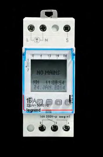
31 DX 3 RCD add on module with measurement & metering N DX 3 time switches N Technical characteristics p. 51 Technical characteristics p Conform to IEC Hpi type: detect faults with AC and DC components, increased Immunity to false tripping Inbuilt measurement/metering option Measurement - V, A, F, PF, KWh, KVA, KVAr, THD Metering - V, A, F, KWh RS 485 port for remote reading Di-electric test button inbuilt Ergonomic test button Scroll button for easy readings RLCD display on front facia For mounting on the right-hand side of 1.5 module per pole DX 3 MCBs Easy & fast association mechanism 70 sq mm terminals Pack Cat.Nos Adjustable metering, 4 pole 415 VA Nominal rating In (A) Number of modules A A 7 Adjustable measurement A 7 Daily and weekly time switch Quick and easy programming due to the option to select day blocks, day blocks can be individually set or selected from the blocks Mon Sun, Mon Fri or Sat Sun Programming with precision to the second Switch times visible in weekly overview on display Pack Cat.Nos Alpharex 3 digital time switches AlphaRex 3 D21, 1 channel AlphaRex 3 D22, 2 channels AlphaRex 3 D21s, 1 channel, with control input Alpharex 3 digital time switches - Astro For switching on/off lights and other electric devices according to the rising/setting of the sun With combination function for creating switching programs in which the devices are switched according to astronomical time and/or fixed preset times Daily astronomical calculation of the sunrise/ sunset times based on the entered location or location coordinates AlphaRex3 D21 astro, 1 channel AlphaRex3 D22 astro, 2 channels Alpharex 3 yearly time switch Yearly and weekly time switch with additional astronomical function for all channels 84 switching programs per channel, comprising: - 28 weekly programs - 28 yearly programs - 28 special programs (priority program) AlphaRex 3 DY21, 1 channel AlphaRex 3 DY22, 2 channels Programming accessories Data key PC adapter for USB port Bold catalogue numbers are products normally available with Legrand (India) stockists. Cat.Nos that are not bold - delivery within 4-8 weeks from the date of order. Bold packing quantity is our mandatory packing. Orders to be placed by Legrand (India) stockists in multiples of the same. Red catalogue numbers: New products 29
32 DX 3 time switches N DX 3 contactors N Technical characteristics p Technical characteristics p. 59 With synchronous (mains-synchronised clock precision) or quartz motor +/-2.5 s/day clock precision (quartz motor) Surface-mounting possible with a wall bracket and a terminal cover (Cat.No ) Unit width: 3 modules of 17.5 mm each Pack Cat.Nos Twilight switches Including light sensor Wire for light sensor: 2 x 1.5 mm 2, maximum wire length: 50 m LED switching status indicator Luxo switch MicroRex analog time switches In accordance with IEC and Manual switching ON/automatic/OFF daily/weekly switching dial with captive segments Clock precision: +/ 5 min for the daily time switch 10 C to +55 C operating temperature MicroRex T31 Daily time switch MicroRex QT31 Daily time switch MicroRex W31 Weekly time switch MicroRex QT11 Daily time switch MicroRex QW11 Weekly time switch Accessory Wall bracket Conform to IEC/EN Space for power supply busbar on top (up to 63 A) Pack Cat.Nos Power contactors CX A 2 NO contactor A 2 NO contactor A 2 NO contactor A 2 NC contactor A 3 NO contactor A 3 NO contactor A 4 NO contactor A 4 NO contactor A 4 NO contactor A 4 NC contactor Signalling auxiliaries for contactors Auxiliary changeover switch For 1 module contactors 16 A to 25 A For 2 module contactors 25 A For 40 and 63 A contactors 30 Bold catalogue numbers are products normally available with Legrand (India) stockists. Cat.Nos that are not bold - delivery within 4-8 weeks from the date of order. Bold packing quantity is our mandatory packing. Orders to be placed by Legrand (India) stockists in multiples of the same. Red catalogue numbers: New products

33 EMDX 3 electrical energy meters 4 rail mounting N EMDX3 multi-function measuring units 4 rail mounting N Technical characteristics p Technical characteristics p Measure the electricity consumed by a single-phase or three-phase circuit downstream of the electricity distribution metering Display electricity consumption in kwh, as well as other values such as current, active energy, reactive energy and power (depending on the catalogue number) Conform to standards IEC /23, IEC and IEC MID compliance ensures accuracy of the metering with a view to recharging for the electricity used Pack Cat.Nos Single-phase meters Direct connection A - 2 modules RS 485 output Three-phase meters Direct connection A - 4 modules RS 485 output Connection with CT A - 4 modules RS 485 and pulse output Conform to standards: - IEC IEC class 0.5 S - IEC class 2 Pack Cat.Nos EMDX 3 modular For mounting on 2 rail Width: 4 modules LCD display Measurement of currents, voltages, active, reactive and apparent power and internal temperature Dual tariff metering: - Active energy consumed - Reactive energy consumed - Operating time - Power factor THD voltages and currents up to order 51 Programmable alarms on all functions Outputs for controlling wiring devices, alarm feedback and pulse feedback EMDX 3 RS 485 unit Data transmission via RS 485 communication interface and pulses Bold catalogue numbers are products normally available with Legrand (India) stockists. Cat.Nos that are not bold - delivery within 4-8 weeks from the date of order. Bold packing quantity is our mandatory packing. Orders to be placed by Legrand (India) stockists in multiples of the same. Red catalogue numbers: New products 31
34 DX 3 MCBs n Technical data Specifications IS/IEC Number of poles SP, SPN, DP, TP, TPN, FP Characteristics C & D Curve Breaking capacity 10 ka 0.5 A to 63 A as per IS/IEC ka for 0.5 A to 25 A as per IEC Rated voltage 230 V / 400 V Current limitation class Class 3 Frequency 50 Hz/ 60 Hz Minimum operating voltage 12 V AC/ DC Enclosures Polyester self extinguishing, heat and fire resistant according to IEC , glow-wire test at 960 C for external parts made of insulating material necessary to retain in position currentcarrying parts and parts of protective circuit (650 C for all other external parts made of insulating material) Mounting position Vertical / Horizontal / Upside down / On the side Fixing On symmetric rail EN/IEC or DIN 35 Maximum cable size Top/Bottom 1 x 1.5 mm² to 35 mm² Rigid cable 2 x 1.5 mm² to 16 mm² Top/Bottom 1 x 1.5 mm² to 25 mm² Flexible cable 2 x 1.5 mm² to 10 mm² Applied connection torque Recommended : 2.5 Nm Minimum : 2 Nm Maximum: 3 Nm Mechanical endurance operations without load Electrical endurance operations with load (under In*cos j = 0.9) 2000 operations under In, DC current Permissible ambient temperature 0.5 to 63A - Maximum C Minimum C Specifications IEC Number of poles SP, DP, TP, FP Breaking capacity 10 ka 80 A to 125 A as per IEC ka for 80 A to 125 A as per IEC Rated voltage 230 V/ 400 V Current limitation class Class 3 Frequency 50 Hz/ 60 Hz Minimum operating voltage 12 V AC/ DC Enclosures Polyester self extinguishing, heat and fire resistant according to IEC , glow-wire test at 960 C for external parts made of insulating material necessary to retain in position currentcarrying parts and parts of protective circuit (650 C for all other external parts made of insulating material) Mounting position Vertical / Horizontal / Upside down / On the side Fixing On symmetric rail EN/IEC or DIN 35 Maximum cable size Top/Bottom 1 x 1.5 mm² to 50 mm² Rigid cable 2 x 1.5 mm² to 25 mm² Top/Bottom 1 x 1.5 mm² to 35 mm² Flexible cable 2 x 1.5 mm² to 20 mm² Applied connection torque Recommended : 2.5 Nm Minimum : 2 Nm Maximum: 3 Nm Mechanical endurance operations without load Electrical endurance operations with load (under In*cos j = 0.9) 2000 operations under In, DC current Permissible ambient temperature 80 to 125A - Maximum C Minimum C Power dissipated in Watt per pole at In Circuit breakers C and D curves In (A) 0,5 1 1, , P 4P Permitted limit as per IEC Impedance per pole (W) = P dissipated In 2 Ambient Temperature / In In (A) - 25 C - 10 C 0 C 10 C 20 C 30 C 40 C 50 C 60 C 70 C 0, Choice of DX 3 MCBs for capacitor banks This table shows the rated current of MCBs to be used when controlling capacitor banks so as to guarantee its function and shortcircuit protection. Overload protection is not necessary since these installations cannot be overloaded. This data refers to shortcircuit protection in absence of harmonics or heavy transitory currents. DX 3 MCB rating in amps C characteristic D characteristic Power of capacitor Single phase Three phase Single phase Three phase bank in KVAR 240 V 415 V 240 V 415 V to to
35 DX 3 MCBs n Technical data Correct polarity connections for DC MCBs Supply terminals When supply is given at lower terminals Single pole MCB Double pole MCB Tripping characteristics Standards has established different tripping characteristics depending on minimum and maximum values of magnetic trip. DX 3 MCB Type Im1 Im2 Typical application 0.5 A to 63 A D 10 In 20 In Protection of cable and appliance which has very high starting currents. 6 A to 63 A C 5 In 10 In Protection of cable used for lighting load, power load and induction loads with high starting current. lm1 - hold limit lm2 - Trip limit DX 3 MCBs versus zero point extinguishing MCBs Supply terminals When supply is given at upper terminals Single pole MCB Double pole MCB Current limiting DX 3 MCB Zero point extinguishing MCB Un = Mains Voltage UB = Arc Voltage ID = Let-through short circuit current IP = Prospective short circuit current Derating of MCB for use with fluorescent lights Ferromagnetic and electronic ballasts have a high inrush current for a short time. These currents can cause the tripping of circuit breakers. At the time of the installation, it should take into account the maximum number of ballasts per circuit breaker that the manufacturers of lamps and ballasts indicate in their catalogues. Influence of the altitude 2000 m 3000 m 4000 m 5000 m Dielectric holding 3000 V 2500 V 2000 V 1500 V Max operational voltage 400 V 400 V 400 V 400 V Derating at 30 C none none none none Derating of MCBs function of the number of devices side by side: When several MCBs are juxtaposed and operate simultaneously, the thermal evacuation of the poles is limited. This results in an increase in operating temperature of the circuit breakers which can cause unwanted tripping. It is recommended to apply the following coefficients to the rated currents. Influence of the altitude Number of circuit breakers side by side Coefficient These values are given by the recommendation of IEC , NF C and EN standards. 33
36 DX 3 MCBs n Technical data Association of protection devices Association is the technique by which the breaking capacity of a MCB is increased by coordinating it with another protection device, placed upstream. This coordination makes it possible to use a protection device with a breaking capacity which is lower than the maximum prospective short-circuit current at its installation point The breaking capacity of a protection device must be at least equal to the maximum short-circuit which may occur at the point at which this device is installed. In exceptional cases, the breaking capacity may be lower than the maximum prospective short-circuit, as long as: It is associated with a device upstream which has the necessary breaking capacity at its own installation point The downstream device and the trunking being protected can withstand the power limited by the association of the devices. Association therefore leads to substantial savings. The association values given in the tables on the following pages are based on laboratory tests carried out in accordance with IEC Note: In the case of single phase circuits (protected by P+N or 2P MCBs) in a 415 V AC supply, supplied upstream by a 3-phase circuit, it is advisable to use the association tables for 230 V. Example of association DPX 250 ER 250 A Breaking capacity = 50 ka Association between distribution boards Association applies to devices installed in the same distribution board as well as in different boards. It is therefore generally possible to benefit from the advantages of the association between Table no 1 devices located, for example, in a main distribution board and in a secondary board. MCB - switch association The switches must be systematically protected by an MCB placed upstream. There is considered to be protection against overloads if the rating of switch I is at least equal to that of the upstream MCB, D. If this is not the case, the thermal stresses (devices and conductors) must be checked. The tables on the following pages give the breaking capacity limits of the MCB - switch associations. Table no 2 Lexic MCB 40 A - c curve Breaking capacity alone = 10 ka Breaking capacity in association with DPX 250 ER = 25 ka 3-level association An association may be created on three levels if one of the conditions below is met. The upstream device A must have an adequate breaking capacity at its installation point. Devices B and C are associated with device A. Simply check that the association values B + A and C + A have the necessary breaking capacity. In this case, there is no need to check the association between devices B and C. The association is made between successive devices: Upstream device A, which has an adequate breaking capacity at its installation point, device C is associated with device B which is in turn associated with device A. Simply check that the association values C+B and B+A have the necessary breaking capacity. In this case, there is no need to check the association between devices A and C. Association in IT connection systems The values given in the tables should only be used for TN and TT systems. Although this practice is not widely used, these values may also be used for installations with IT systems. It is therefore advisable to check that each protection device, on its own, can break, on a single pole, the maximum double fault current at the point in question. 34
37 DX 3 MCBs Discrimination of protection devices Discrimination is a technique which consists of coordinating the protection in such a way that a fault on one circuit only trips the protection placed at the head of that circuit, thus avoiding rendering the remainder of the installation inoperative. Discrimination improves continuity of service and safety of the installation Discrimination rules are set by the regulations concerning public buildings and for safety installations in general. Discrimination between A and B is said to be total if it is provided up to the value of the maximum prospective short-circuit at the point at which B is installed. By extension, in the tables on the following pages, total discrimination, indicated by T, means that there is discrimination up to the breaking capacity of device B. Discrimination between A and B is said to be partial in the other cases. The discrimination limit (given in the following tables) is therefore defined. This gives the short-circuit current value below which only MCB B will open and above which MCB A will also open. There are a number of techniques for providing discrimination: Current discrimination, used for terminal circuits which have low shortcircuits. Time discrimination, provided by a delay on tripping the upstream MCB Logical discrimination, a variant of time discrimination, used on electronic MCBs via a special link between the devices. Since almost all faults occur during use, Lexic MCB 40 A DPX 250 ER 160 A partial discrimination may be adequate if the discrimination limit is higher than the value of the maximum short-circuit which may occur at the point of use (or at the end of the trunking). This is referred to as operating discrimination. This technique is very often adequate, more economical and less restricting in terms of implementation. The discrimination limit for the association DPX 250 ER (160 A) with Lexic MCB 40 A (C curve) is 6 ka. Since the prospective ISC at the point of installation is 8 ka, the discrimination is not total. However, there is discrimination at the point of use at which the prospective short-circuit is only 3 ka. Current discrimination This technique is based on the off set of the intensity of the tripping curves of the upstream and downstream MCBs. It is checked by comparing these curves and checking that they do not overlap. It applies for the overload zone and the short-circuit zone, and the further apart the ratings of the devices, the better the discrimination. On overloads To have discrimination in the overload zone, the ratio of the setting currents (Ir) must be at least 2. On short-circuits To have discrimination in the short circuit zone, the ratio of the magnetic setting currents (Im) must be at least 1.5. The discrimination limit is then equal to the magnetic release current ImA of the upstream MCB. The discrimination is then total as long as IscB is less than ImA. Current discrimination is therefore very suitable for terminal circuits where the short-circuits are relatively weak. In other cases, time discrimination may be used together with current discrimination. Current discrimination The discrimination is total for Isc B When the downstream MCB B is a limiting device, the short-circuit current is limited in terms of time and amplitude. The discrimination is therefore total if the limited current IscB, which device B allows to pass, is lower than the tripping current of device A Time discrimination This technique is based on the offset of the times of the tripping curves of the MCBs in series. It is checked by comparing the curves and is used for discrimination in the short-circuit zone. It is also used in addition to current discrimination in order to obtain discrimination beyond the magnetic setting current of the upstream MCB (ImA). The following is necessary: It must be possible to set a time delay on the upstream MCB The upstream MCB must be able to withstand the short-circuit current and its effects for the whole period of the time delay The trunking through which this current passes must be able to withstand the thermal stresses (I 2 t). The non-tripping time of the upstream device must be longer than the breaking time (including any time delay) of the downstream device. DPX MCBs have a number of time delay setting positions for creating discrimination with a number of stages. 35
38 DX 3 MCBs n Technical data Coordination between modular circuit-breakers and fuses, three-phase network (+ neutal) 400 / 415 V± according to standard IEC/EN : For TT or TN neutral system in 240/415 V network, to know the breaking capacity of the combination of a double pole breaker (connected between phase and neutral under 230 V) downstream of a triple-pole circuit-breaker, take the values shown in Tables 230/400 V. Fuse upstream gg Type MCB downstream 20A 25A 32A 40A 50A 63A 80A 100A 125A 160A DX A/10 ka C and D curves 6A 100kA 100kA 100kA 100kA 100kA 100kA 100kA 100kA 100kA 40kA 10A 100kA 100kA 100kA 100kA 100kA 100kA 100kA 100kA 100kA 40kA 16A - 100kA 100kA 100kA 100kA 100kA 100kA 100kA 100kA 40kA 20A kA 100kA 100kA 100kA 100kA 100kA 100kA 40kA 25A kA 100kA 100kA 100kA 100kA 100kA 40kA 32A kA 100kA 100kA 100kA 100kA 40kA 40A kA 100kA 100kA 100kA 40kA 50A kA 100kA 100kA 40kA 63A kA 100kA 100kA 40kA Fuse upstream am Type MCB downstream 20A 25A 32A 40A 50A 63A 80A 100A 125A 160A DX A/10 ka C and D curves 6A 100kA 100kA 100kA 100kA 100kA 100kA 100kA 100kA 100kA 40kA 10A 100kA 100kA 100kA 100kA 100kA 100kA 100kA 100kA 100kA 40kA 16A - 100kA 100kA 100kA 100kA 100kA 100kA 100kA 100kA 40kA 20A kA 100kA 100kA 100kA 100kA 100kA 100kA 40kA 25A kA 100kA 100kA 100kA 100kA 100kA 40kA 32A kA 100kA 100kA 100kA 100kA 40kA 40A kA 100kA 100kA 100kA 40kA 50A kA 100kA 100kA 40kA 63A kA 100kA 100kA 40kA All these values are also valid for circuit breakers associated to differential blocks. According to the curves and ratings of circuit breakers, attention to the threshold and size of upstream fuse which must necessarily be higher. Coordination between modular circuit-breakers, three-phase network (+ neutal) 400 / 415 V± according to IEC/EN : For TT or TN neutral system in 230/400 V network, to know the breaking capacity of the combination of a double pole breaker (connected between phase and neutral under 230 V) downstream of a triple-pole circuit-breaker, take the values shown in Tables 230/400 V. MCB upstream DX /16kA C and D Curves MCB downstream 25A 32A 40A 50A 63A 80A 100A 125A DX A C Curves 6A 16kA 16kA 16A 16kA 16kA 16kA 16kA 16kA 10A 16kA 16kA 16kA 16kA 16kA 16kA 16kA 16kA 16A 16kA 16kA 16kA 16kA 16kA 16kA 16kA 16kA 20A 16kA 16kA 16kA 16kA 16kA 16kA 16kA 16kA 25A - 16kA 16kA 16kA 16kA 16kA 16kA 16kA 32A kA 16kA 16kA 16kA 16kA 16kA 40A kA 16kA 16kA 16kA 16kA 50A kA 16kA 16kA 16kA 63A kA 16kA 16kA m.c.b. upstream DX 3 25kA C and D Curves MCB downstream 25A 32A 40A 50A 63A 80A 100A 125A DX A C Curves 6A 25kA 25kA 25kA 25kA 25kA 25kA 25kA 25kA 10A 25kA 25kA 25kA 25kA 25kA 25kA 25kA 25kA 16A 25kA 25kA 25kA 25kA 25kA 25kA 25kA 25kA 20A 25kA 25kA 25kA 25kA 25kA 25kA 25kA 25kA 25A - 25kA 25kA 25kA 25kA 25kA 25kA 25kA 32A kA 25kA 25kA 25kA 25kA 25kA 40A kA 25kA 25kA 25kA 25kA 50A kA 25kA 25kA 25kA 63A kA 25kA 25kA All these values are also valid for circuit breakers associated to RCD add-on modules. According to the curves and ratings of circuit breakers, attention to the magnetic threshold and to the size of upstream circuit breakers which must necessarily be higher. 36
39 DX 3 MCBs n Technical data Coordination between modular circuit-breakers, three-phase network (+ neutal) 400 / 415 V± according to IEC/EN : For TT or TN neutral system in 240/415 V network, to know the breaking capacity of the combination of a double pole breaker (connected between phase and neutral under 230 V) downstream of a triple-pole circuit-breaker, take the values shown in Tables 240/415 V. MCB upstream DX 3 36kA DX 3 50kA C Curve C and D Curves MCB downstream 25A 32A 40A 50A 63A 80A 25A 32A 40A 50A 63A 6A 36kA 36kA 36kA 36kA 36kA 36kA 50kA 50kA 50kA 50kA 50kA 10A 36kA 36kA 36kA 36kA 36kA 36kA 50kA 50kA 50kA 50kA 50kA 16A 36KA 36kA 36kA 36kA 36kA 36kA 50kA 50kA 50kA 50kA 50kA 20A 36kA 36kA 36kA 36kA 36kA 36kA 50kA 50kA 50kA 50kA 50kA DX A 25A C Curves - 36kA 36kA 36kA 36kA 36kA - 50kA 50kA 50kA 50kA 32A kA 36kA 36kA 36kA kA 50kA 50kA 40A kA 36kA 36kA kA 50kA 50A kA 36kA kA 63A kA All these values are also valid for circuit breakers associated to RCD add-on modules. According to the curves and ratings of circuit breakers, attention to the magnetic threshold and to the size of upstream circuit breakers which must necessarily be higher. Coordination between modular circuit-breakers (MCB) and Moulded Case Circuit Breakers (MCCBs), three-phase network (+ neutal) 400 / 415 V± according to standard IEC/EN : For TT or TN neutral system in 240/415 V network, to know the breaking capacity of the combination of a double pole breaker (connected between phase and neutral under 230 V) downstream of a triple-pole circuit-breaker, take the values shown in Tables 240/415 V. MCCB upstream DPX / DPX RCD 16kA MCB downstream 16A 25A 40A 63A 80A 100A 125A 160A DX A/10 ka C and D curves 6A 16kA 16kA 16kA 16kA 16kA 16kA 16kA 16kA 10A 16kA 16kA 16kA 16kA 16kA 16kA 16kA 16kA 16A - 16kA 16kA 16kA 16kA 16kA 16kA 16kA 20A - 16kA 16kA 16kA 16kA 16kA 16kA 16kA 25A kA 16kA 16kA 16kA 16kA 16kA 32A kA 16kA 16kA 16kA 16kA 16kA 40A kA 16kA 16kA 16kA 16kA 50A kA 16kA 16kA 16kA 16kA 63A kA 16kA 16kA 16kA MCCB upstream DPX / DPX RCD kA MCB downstream 16A 25A 40A 63A 80A 100A 125A 160A DX A/10 ka C and D curves 6A 25kA 25kA 25kA 25kA 25kA 25kA 25kA 25kA 10A 25kA 25kA 25kA 25kA 25kA 25kA 25kA 25kA 16A - 25kA 25kA 25kA 25kA 25kA 25kA 25kA 20A - 25kA 25kA 25kA 25kA 25kA 25kA 36kA 25A kA 25kA 25kA 25kA 25kA 25kA 32A kA 25kA 25kA 25kA 25kA 25kA 40A kA 25kA 25kA 25kA 25kA 50A kA 25kA 25kA 25kA 25kA 63A kA 25kA 25kA 25kA All these values are also valid for circuit breakers associated to differential blocks. According to the curves and ratings of circuit breakers, attention to the magnetic threshold and to the size of upstream circuit breakers which must necessarily be higher. 37
40 DX 3 MCBs n Technical data Coordination between modular circuit-breakers (MCB) and Moulded Case Circuit Breakers (MCCBs), three-phase network (+ neutal) 400 / 415 V± according to standard IEC/EN : For TT or TN neutral system in 240/415 V network, to know the breaking capacity of the combination of a double pole breaker (connected between phase and neutral under 230 V) downstream of a triple-pole circuit-breaker, take the values shown in Tables 240/415 V. MCCB upstream DPX / DPX RCD (Thermal- Magnetic & Electronic) kA - 70kA MCB downstream 100A 160A 200A 250A DX A/10 ka C and D curves 6A 25kA 25kA 25kA 25kA 10A 25kA 25kA 25kA 25kA 16A 25kA 25kA 25kA 25kA 20A 25kA 25kA 25kA 25kA 25A 25kA 25kA 25kA 25kA 32A 25kA 25kA 25kA 25kA 40A 25kA 25kA 25kA 25kA 50A 25kA 25kA 25kA 25kA 63A 25kA 25kA 25kA 25kA MCCB upstream DPX / H / L 250 (Thermal -Magnetic & electronic) DPX 400AB DPX / DPXH / DPXL 630 (Thermal -Magnetic & electronic) kA 36kA kA MCB downstream 25A 40A 63A 100A 160A 250A 320A 400A 250A 320A 400A 500A 630A 6A 25kA 25kA 25kA 25kA 25kA 25kA 25kA 25kA 25kA 25kA 25kA 25kA 25kA 10A 25kA 25kA 25kA 25kA 25kA 25kA 25kA 25kA 25kA 25kA 25kA 25kA 25kA 16A 25kA 25kA 25kA 25kA 25kA 25kA 25kA 25kA 25kA 25kA 25kA 25kA 25kA 20A 25kA 25kA 25kA 25kA 25kA 25kA 25kA 25kA 25kA 25kA 25kA 25kA 25kA DX A/10 ka 25A C and D curves - 25kA 25kA 25kA 25kA 25kA 25kA 25kA 25kA 25kA 25kA 25kA 25kA 32A - 25kA 25kA 25kA 25kA 25kA 25kA 25kA 25kA 25kA 25kA 25kA 25kA 40A kA 25kA 25kA 25kA 20kA 20kA 20kA 20kA 20kA 20kA 20kA 50A kA 25kA 25kA 25kA 20kA 20kA 20kA 20kA 20kA 20kA 20kA 63A kA 20kA 20kA 20kA 20kA 20kA 20kA 20kA 20kA 20kA All these values are also valid for circuit breakers associated to differential blocks. According to the curves and ratings of circuit breakers, attention to the magnetic (or electronic) threshold and to the size of upstream circuit breakers which must necessarily be higher. Coordination between modular circuit-breakers (MCB) and Moulded Case Circuit Breakers (MCCBs), three-phase network (+ neutal) 400 / 415 V± according to standard IEC/EN : For TT or TN neutral system in 240/415 V network, to know the breaking capacity of the combination of a double pole breaker (connected between phase and neutral under 230 V) downstream of a triple-pole circuit-breaker, take the values shown in Tables 240/415 V. DPX / H / L 1250 (Thermo- Magnetic) MCCB upstream DPX / H 1600 (Electronic) kA 36 70kA MCB downstream 500 to 1250A 630 to 1600A 6A 25kA 25kA 10A 25kA 25kA 16A 25kA 25kA 20A 25kA 25kA DX A/10 ka 25A C and D curves 20kA 20kA 32A 16kA 16kA 40A 16kA 16kA 50A 16kA 16kA 63A 16kA 16kA All these values are also valid for circuit breakers associated to differential blocks. According to the curves and ratings of circuit breakers, attention to the magnetic (or electronic) threshold and to the size of upstream circuit breakers which must necessarily be higher. Coordination between modular circuit-breakers and fuses, three-phase network (+ neutal) 230 / 240 V± according to standard IEC/EN : Fuse upstream gg Type MCB downstream 20A 25A 32A 40A 50A 63A 80A 100A 125A 160A DX A/10 ka C and D curves 6A 100kA 100kA 100kA 100kA 100kA 100kA 100kA 100kA 100kA 40kA 10A 100kA 100kA 100kA 100kA 100kA 100kA 100kA 100kA 100kA 40kA 16A - 100kA 100kA 100kA 100kA 100kA 100kA 100kA 100kA 40kA 20A kA 100kA 100kA 100kA 100kA 100kA 100kA 40kA 25A kA 100kA 100kA 100kA 100kA 100kA 40kA 32A kA 100kA 100kA 100kA 100kA 40kA 40A kA 100kA 100kA 100kA 40kA 50A kA 100kA 100kA 40kA 63A kA 100kA 100kA 40kA Fuse upstream am Type MCB downstream 20A 25A 32A 40A 50A 63A 80A 100A 125A 160A DX A/10 ka C and D curves 6A 100kA 100kA 100kA 100kA 100kA 100kA 100kA 100kA 100kA 40kA 10A 100kA 100kA 100kA 100kA 100kA 100kA 100kA 100kA 100kA 40kA 16A - 100kA 100kA 100kA 100kA 100kA 100kA 100kA 100kA 40kA 20A kA 100kA 100kA 100kA 100kA 100kA 100kA 40kA 25A kA 100kA 100kA 100kA 100kA 100kA 40kA 32A kA 100kA 100kA 100kA 100kA 40kA 40A kA 100kA 100kA 100kA 40kA 50A kA 100kA 100kA 40kA 63A kA 100kA 100kA 40kA All these values are also valid for circuit breakers associated to differential blocks. According to the curves and ratings of circuit breakers, attention to the threshold and to the size of upstream fuses which must necessarily be higher. 38
41 DX 3 MCBs n Technical data Coordination between modular circuit-breakers, three-phase network (+ neutal) 230 / 240 V± according to IEC/EN : MCB upstream DX /16kA B, C and D Curves MCB downstream 25A 32A 40A 50A 63A 80A 100A 125A DX A C Curves 6A 32kA 32kA 25kA 25kA 25kA 25kA 25kA 25kA 10A 32kA 32kA 25kA 25kA 25kA 25kA 25kA 25kA 16A 32kA 32kA 25kA 25kA 25kA 25kA 25kA 25kA 20A 32kA 32kA 25kA 25kA 25kA 25kA 25kA 25kA 25A - 32kA 25kA 25kA 25kA 25kA 25kA 25kA 32A kA 25kA 25kA 25kA 25kA 25kA 40A kA 25kA 25kA 25kA 25kA 50A kA 25kA 25kA 25kA 63A kA 25kA 25kA MCB upstream DX 3 25kA MCB downstream 25A 32A 40A 50A 63A 80A 100A 125A DX A C Curves 6A 50kA 50kA 25kA 25kA 25kA 25kA 25kA 25kA 10A 50kA 50kA 25kA 25kA 25kA 25kA 25kA 25kA 16A 50kA 50kA 25kA 25kA 25kA 25kA 25kA 25kA 20A 50kA 50kA 25kA 25kA 25kA 25kA 25kA 25kA 25A - 50kA 25kA 25kA 25kA 25kA 25kA 25kA 32A kA 25kA 25kA 25kA 25kA 25kA 40A kA 25kA 25kA 25kA 25kA 50A kA 25kA 25kA 25kA 63A kA 25kA 25kA All these values are also valid for circuit breakers associated to RCD add-on modules. According to the curves and ratings of circuit breakers, attention to the magnetic threshold and to the size of upstream circuit breakers which must necessarily be higher. Coordination between modular circuit-breakers, three-phase network (+ neutal) 230 / 240 V± according to IEC/EN : MCB upstream DX 3 36kA DX 3 50kA MCB downstream 25A 32A 40A 50A 63A 80A 25A 32A 40A 50A 63A 6A 50kA 50kA 50kA 50kA 50kA 50kA 50kA 50kA 50kA 50kA 50kA 10A 50kA 50kA 50kA 50kA 50kA 50kA 50kA 50kA 50kA 50kA 50kA 16A 50kA 50kA 50kA 50kA 50kA 50kA 50kA 50kA 50kA 50kA 50kA 20A 50kA 50kA 50kA 50kA 50kA 50kA 50kA 50kA 50kA 50kA 50kA DX A 25A C Curves - 50kA 50kA 50kA 50kA 50kA - 50kA 50kA 50kA 50kA 32A kA 50kA 50kA 50kA kA 50kA 50kA 40A kA 50kA 50kA kA 50kA 50A kA 50kA kA 63A kA All these values are also valid for circuit breakers associated to RCD add-on modules. According to the curves and ratings of circuit breakers, attention to the magnetic threshold and to the size of upstream circuit breakers which must necessarily be higher. Coordination between modular circuit-breakers (MCB) and Moulded Case Circuit Breakers (MCCBs), three-phase network (+ neutal) 230 / 240 V± according to standard IEC/EN : MCCB upstream DPX / DPX RCD 16kA MCB downstream 16A 25A 40A 63A 80A 100A 125A 160A DX A/10 ka C and D curves 6A 28kA 28kA 28kA 28kA 28kA 28kA 28kA 28kA 10A 28kA 28kA 28kA 28kA 28kA 28kA 28kA 28kA 16A - 28kA 28kA 28kA 28kA 28kA 28kA 28kA 20A - 28kA 28kA 28kA 28kA 28kA 28kA 28kA 25A kA 28kA 28kA 28kA 28kA 28kA 32A kA 28kA 28kA 28kA 28kA 28kA 40A kA 28kA 28kA 28kA 28kA 50A kA 28kA 28kA 28kA 28kA 63A kA 28kA 28kA 28kA All these values are also valid for circuit breakers associated to differential blocks. According to the curves and ratings of circuit breakers, attention to the magnetic threshold and to the size of upstream circuit breakers which must necessarily be higher. 39
42 DX 3 MCBs n Technical data Coordination between modular circuit-breakers (MCB) and Moulded Case Circuit Breakers (MCCBs), three-phase network (+ neutal) 230 / 240 V± according to standard IEC/EN : MCCB upstream DPX / DPX RCD 25kA MCB downstream 16A 25A 40A 63A 80A 100A 125A 160A DX A/10 ka C and D curves 6A 40kA 40kA 40kA 40kA 40kA 40kA 40kA 40kA 10A 40kA 40kA 40kA 40kA 40kA 40kA 40kA 40kA 16A - 40kA 40kA 40kA 40kA 40kA 40kA 40kA 20A - 40kA 40kA 40kA 40kA 40kA 40kA 40kA 25A kA 40kA 40kA 40kA 40kA 40kA 32A kA 40kA 40kA 40kA 40kA 40kA 40A kA 40kA 40kA 40kA 40kA 50A kA 40kA 40kA 40kA 40kA 63A kA 40kA 40kA 40kA MCCB upstream DPX / DPX RCD 36-50kA MCB downstream 16A 25A 40A 63A 80A 100A 125A 160A DX A/10 ka C and D curves 6A 50kA 50kA 50kA 50kA 50kA 50kA 50kA 50kA 10A 50kA 50kA 50kA 50kA 50kA 50kA 50kA 50kA 16A - 50kA 50kA 50kA 50kA 50kA 50kA 50kA 20A - 50kA 50kA 50kA 50kA 50kA 50kA 50kA 25A kA 50kA 50kA 50kA 50kA 50kA 32A kA - 50kA 50kA 50kA 50kA 40A kA 50kA 50kA 50kA 50kA 50A 50kA 50kA 50kA 50kA 50kA 63A 50kA 50kA 50kA 50kA All these values are also valid for circuit breakers associated to differential blocks. According to the curves and ratings of circuit breakers, attention to the magnetic threshold and to the size of upstream circuit breakers which must necessarily be higher. Coordination between modular circuit-breakers (MCB) and Moulded Case Circuit Breakers (MCCBs), three-phase network (+ neutal) 230 / 240 V± according to standard IEC/EN : MCCB upstream DPX / DPX RCD (Thermal-magnetic & electronic) 25kA MCB downstream 100A 160A 200A 250A DX A/10 ka C and D curves 6A 40kA 40kA 40kA 40kA 10A 40kA 40kA 40kA 40kA 16A 40kA 40kA 40kA 40kA 20A 40kA 40kA 40kA 40kA 25A 40kA 40kA 40kA 40kA 32A 40kA 40kA 40kA 40kA 40A 40kA 40kA 40kA 40kA 50A 40kA 40kA 40kA 40kA 63A 40kA 40kA 40kA 40kA All these values are also valid for circuit breakers associated to differential blocks. 40
43 DX 3 MCBs n Technical data Coordination between modular circuit-breakers (MCB) and Moulded Case Circuit Breakers (MCCBs), three phase network (+ neutal) 230 / 240 V± according to standard IEC/EN : MCCB upstream DPX / DPX RCD (Thermal-magnetic & electronic) DPX / H / L 250 (Thermal-magnetic & electronic) kA kA MCB downstream 100A 160A 200A 250A 25A 40A 63A 100A 160A 250A 6A 50kA 50kA 50kA 50kA 50kA 50kA 50kA 50kA 50kA 50kA 10A 50kA 50kA 50kA 50kA 50kA 50kA 50kA 50kA 50kA 50kA 16A 50kA 50kA 50kA 50kA 50kA 50kA 50kA 50kA 50kA 50kA 20A 50kA 50kA 50kA 50kA 50kA 50kA 50kA 50kA 50kA 50kA DX A/10 ka 25A C and D curves 50kA 50kA 50kA 50kA - 50kA 50kA 50kA 50kA 50kA 32A 50kA 50kA 50kA 50kA - 50kA 50kA 50kA 50kA 50kA 40A 50kA 50kA 50kA 50kA kA 50kA 50kA 50kA 50A 50kA 50kA 50kA 50kA kA 50kA 50kA 50kA 63A 50kA 50kA 50kA 50kA kA 50kA 50kA MCCB upstream DPX 400AB DPX / DPXH / DPXL 630MT (Thermal-magnetic & electronic) 36kA kA MCB downstream 320A 400A 250A 320A 400A 500A 630A 6A 50kA 50kA 50kA 50kA 50kA 50kA 50kA 10A 50kA 50kA 50kA 50kA 50kA 50kA 50kA 16A 50kA 50kA 50kA 50KA 50kA 50kA 50KA 20A 50kA 50kA 50kA 50kA 50kA 50kA 50kA DX A/10 ka 25A C and D curves 50kA 50kA 50kA 50kA 50kA 50kA 50kA 32A 50kA 50kA 50kA 50kA 50kA 50kA 50kA 40A 50kA 50kA 50kA 50kA 50kA 50kA 50kA 50A 36kA 36kA 36kA 36kA 36kA 36kA 36kA 63A 36kA 36kA 36kA 36kA 36kA 36kA 36kA All these values are also valid for circuit breakers associated to differential blocks. According to the curves and ratings of circuit breakers, attention to the magnetic (or electronic) threshold and to the size of upstream circuit breakers which must necessarily be higher. Coordination between modular circuit-breakers(mcb) and Moulded Case Circuit Breakers (MCCBs), three phase network (+ neutal) 230 / 240 V± according to standard IEC/EN : DPX / H / L 1250 (Thermalmagnetic) MCCB upstream DPX / H 1600 (electronic) kA 36 70kA MCB downstream 500 to 1250A 630 to 1600A 6A 50kA 50kA 10A 50kA 50kA 16A 50kA 50kA 20A 50kA 50kA DX A/10 ka 25A C and D curves 50kA 50kA 32A 50kA 50kA 40A 50kA 50kA 50A 36kA 36kA 63A 36kA 36kA All these values are also valid for circuit breakers associated to differential blocks. According to the curves and ratings of circuit breakers, attention to the magnetic (or electronic) threshold and to the size of upstream circuit breakers which must necessarily be higher. Selectivity between two levels of protection The downstream circuit breaker must always have a magnetic threshold and a rated current lower than those of the upstream protection. Selectivity is indicated total (T) if there is selectivity up to the value of breaking capacity (according to IEC / EN ) of the downstream circuit breaker. Selectivity between modular circuits breakers and fuses: Selectivity limit at 400 V±: values in Ampere. Fuse upstream gg Type MCB downstream 32A 40A 50A 63A 80A 100A 125A 160A DX A/10 ka C and D curves T = Total discrimination 6A T T 10A T 16A A A A A A A Fuse upstream am Type MCB downstream 25A 32A 40A 50A 63A 80A 100A 125A 160A DX A/10 ka C and D curves 6A T T T 10A T T 16A T T 20A T 25A A A A A
44 DX 3 MCBs n Technical data Selectivity between modular circuits breakers: Selectivity limit at 400 V±: values in Ampere. MCB upstream DX 3 25kA MCB downstream 10A 16A 20A 25A 32A 40A 50A 63A 80A 100A 125A DX A/10 ka C and D curves T = Total discrimination 6A T T 10A T 16A A A A A A A MCB upstream DX 3 25kA MCB downstream 10A 16A 20A 25A 32A 40A 50A 63A 80A 100A 125A DX A/10 ka C and D curves 6A T T 10A T 16A A A A A A A Selectivity between modular circuits breakers: Selectivity limit at 400 V±: values in Ampere. MCB upstream DX 3 25kA MCB downstream 10A 16A 20A 25A 32A 40A 50A 63A 80A 100A 125A DX A/10 ka C and D curves 6A T T 10A T 16A A A A A A A MCB upstream DX 3 36kA MCB downstream 10A 16A 20A 25A 32A 40A 50A 63A 80A DX A/10 ka C and D curves T = Total discrimination 6A A A A A A A A A
45 DX 3 MCBs n Technical data Selectivity between modular circuits breakers: Selectivity limit at 415 V±: values in Ampere. MCB upstream DX 3 50kA MCB downstream 10A 16A 20A 25A 32A 40A 50A 63A DX A/10 ka C and D curves 6A A A A A A A A A MCB upstream DX 3 50kA MCB downstream 10A 16A 20A 25A 32A 40A 50A 63A DX A/10 ka C and D curves 6A A A A A A A A A Selectivity between modular circuits breakers: Selectivity limit at 415 V±: values in Ampere. MCB upstream DX 3 50kA MCB downstream 10A 16A 20A 25A 32A 40A 50A 63A DX A/10 ka C and D curves 6A A A A A A A A A Selectivity between modular circuits breakers (MCB) and Moulded Case Circuit Breakers (MCCBs): Selectivity limit at 415 V±: values in Ampere. MCCB upstream DPX DPX RCD kA MCB downstream 16A 25A 40A 63A 80A 100A 125A 160A DX A/ 10 ka C and D curves T = Total discrimination 6A T T T T T 10A T T T T 16A T T T 20A T T 25A T 32A A A A Selectivity between modular circuits breakers (MCB) and Moulded Case Circuit Breakers (MCCBs): Selectivity limit at 415 V±: values in Ampere. MCCB upstream DPX DPX diff (Thermo-magnetic & electronic) DPX 400AB DPX / H / L 1250 (Thermomagnetic) DPX / H 1600 (electronic) kA 36kA kA 36 70kA MCB downstream 100A 160A 200A 250A 320A 400A 500 to 1250A 630 to 1600A 6A T T T T T T T T 10A T T T T T T T T 16A T T T T T T T T 20A T T T T T T T T DX A/10 ka 25A C and D curves T T T T T T T T 32A 5000 T T T T T T T 40A 5000 T T T T T T T 50A 4000 T T T T T T T 63A 4000 T T T T T T T 43
46 DX 3 MCBs n Technical data Time current characteristics for C curve Rating - 6 to 63A Ref. calibration Temp. : 30 0 C Ref. standard : IS / IEC Time current characteristics for A Rating - 80A to 125A Ref. calibration Temp. : 30 0 C Ref. standard : IEC Multiple of rated current Multiple of rated current Time current characteristics for D curve Rating to 63A Ref. calibration Temp. : 30 0 C Ref. standard : IS / IEC Multiple of rated current 44
47 DX 3 MCBs n Selection chart* DX 3 MCBs (10 ka) and RCBOs 3 phase motor application Motor MCB rating (A) H.P. KW Star Delta DOL A A A A A A 10 A A 10 A A 16 A A 20 A A 25 A A 32 A A 32 A A 40 A A 50 A A 63 A A - n Technical data Isolators Specifications IEC Number of poles DP, TP, FP Utilization category AC22A Rated operational voltage and frequency 415 V, 50/60 Hz Insulation voltage Ui 500 V AC Impulse voltage Uimp 6 kv Short circuit making capacity Icm 1000 A Endurance Electrical operations with load AC22A Mechanical operation Mounting position Vertical / Horizontal / Upside down / On the side Fixing On symmetric rail EN/IEC or DIN 35 Maximum cable size Top/Bottom 1 x 1.5 mm² to 35 mm² Rigid cable 2 x 1.5 mm² to 16 mm² Top/Bottom 1 x 1.5 mm² to 25 mm² Flexible cable 2 x 1.5 mm² to 10 mm² Applied connection torque Recommended : 3 Nm Minimum : 2 Nm Maximum: 3.5 Nm Permissible ambient temperature Maximum C Minimum C For MCB/RCBO ratings : Single phase = P = VI Three phase = P = 3 VI Cos ϕ = x VI x 0.8 Note : One lighting circuit can have upto 800 W or upto 10 points. One power circuit can have upto 3000 W or upto 2 power points. * The data given above is only for guidance. The exact rating must be selected only after considering the motor characteristics. 45
48 DX 3 RCDS Technical data for DX 3 RCDs Specification IS (part 1) 2008 IEC RCCB Type AC Type A-S Type Hpi IEC EN EN IEC No. of modules - Double pole Electrical characteristics - Four pole Nominal rating In (A) - Double pole 25, 40, 63, 80, , 80 25, 40, 63, 80 - Four pole 25, 40, 63, 80, , 40, 63, 80 25, 40, 63, 80 Rated sensitivity (ma) - Double pole 30, 100, Four pole 30, 100, Rated frequency (Hz) 50 / / / 60 Rated operating voltage - Double pole Ue (V AC) - Four pole 230 / Minimum operating voltage (V AC) Minimum operating voltage for test button (V AC) (1) - Double pole Four pole Rated insulation - Double pole voltage Ui (V AC) - Four pole Rated impulse withstand voltage Uimp (kv) Breaking capacity As per IS (part 1) 2008, IEC Rated making & breaking capacity (Im) Rated residual making & breaking capacity (I m) - Up to 40 A 500 A A - From 63 A and above 10 x In 630 A 630 A - Up to 40 A 1000 A A - From 63 A and above 1000 A 1000 A 1000 A Rated conditional short circuit current (Inc) A A A Rated conditional residual short circuit current (I c) A A A Rated service short circuit capacity (Ics) Rated short circuit capacity (Icn) Operating temperature ( 0 C) - 25 to to to 70 Endurance (0.C cycle) - Mechanical 20,000 20,000 20,000 - On load at in X cos ϕ ,000 10,000 10,000 - Via test button 2,000 2,000 2,000 - By fault current (sensitivity) 2,000 2,000 2,000 Testing By pressing test button grey dolly will come to OFF position It is recommended to test RCCB once a month Fault indication - Earth leakage Grey dolly will come to OFF position By pressing test button grey dolly will come to OFF position It is recommended to test RCCB once a month Grey dolly will come to OFF position By pressing test button, grey dolly will come to off position It is recommended to test RCCB once a month Grey dolly will come to off position - Overload and shortcut Resetting Switch on grey dolly Switch on grey dolly Switch on grey dolly Terminals - Rigid 1-35 sq. mm 1-35 sq. mm 1-35 sq. mm Type of protection - Flexible 1-25 sq. mm 1-25 sq. mm 1-25 sq. mm Earth leakage Overload Short circuit Add on electrical accessories* Auxiliary Fault signaling Shunt trip Under voltage Over voltage * - Accessories are mounted on the left hand side of the product. At a time a maximum of three accessories can be mounted. (1) - Between phase and neutral 46
49 RCBO Type AC Type AC - 2 & 4 modules Type Hpi Type A IS (part 2) 2008 IEC NFC EN IEC EN IEC EN IEC , 10, 16, 25, 32, 40, 63 6, 10, 16, 20, 25, 32 25, 32, 40 25, 32, 40 16, 25, 32, 40, 63 10, 16, 20, 25, , 100, , , , 100, / / As per IS (part 2) 2008, IEC A 6000 A 6000 A 6000 A A A 3000 A 3000 A 3000 A A A 6000 A 6000 A 6000 A A 6000 A 6000 A 6000 A - 25 to to to to 70 20,000 20,000 20,000 20,000 10,000 10,000 10,000 10,000 1,000 1,000 1,000 1,000 1,000 1,000 1,000 1,000 By pressing test button, black dolly will come to off position It is recommended to test RCBO once a month Black & blue dolly will come to off position Black dolly will come to off position By pressing test button, black dolly will come to off position It is recommended to test RCBO once a month Black dolly will come to off position & blue indicator will appear on front face window Black dolly will come to off position By pressing test button, black dolly will come to off position It is recommended to test RCBO once a month Black dolly will come to off position & blue indicator will appear on front face window Black dolly will come to off position By pressing test button, black dolly will come to off position It is recommended to test RCBO once a month Black dolly will come to off position & blue indicator will appear on front face window Black dolly will come to off position Switch on black dolly Switch on black dolly Switch on black dolly Switch on black dolly 1-35 sq. mm sq. mm sq. mm sq. mm 1-25 sq. mm sq. mm sq. mm sq. mm 47
50 DX 3 DX 3 RCDs n Technical data Short-circuit withstanding capacity of RCCBs (in ka) RCD downstream DX 3 MCB upstream P P Marking example : Type A Type AC Type A-S Type Hpi n Technical data Nature and consequences of electrical risks Direct and indirect contact All electrical risks for people are the result of direct or indirect contact. What are these contacts? And how can we protect ourselves against them? All the answers appear in the following section. Electrical risks do not just concern people : these risks - especially fire affect installations as well. A 500 ma current, for example, flowing through combustible material is sufficient to ignite such material after a certain time. Every electrical installation is subject to current leakages which can vary considerably depending on such factors as the installation's condition, age, environment, etc. These current leaks may flow through the fabric of the building (trunking, metal girders or other metal components), generating heat which in turn may lead to fire. Direct contacts Direct contact is caused by humans and may be due to either carelessness or clumsiness. What is a direct contact? How can we protect ourselves? Here are the answers... This is when someone makes contact with a live electrical component of a device or installation. For example : a person inadvertently touching a live cable. a child sticking a metal object into a power socket. using male/male extensions or unprotected test cables. In this case only basic protection is effective Other examples Someone touching a live busbar in a distribution panel or cabinet, or someone touching flush-mounted electrical trunking with the end of a tool, etc. In this case basic protection plus additional protection is effective. How can we protect ourselves? There are two ways (independent of the neutral earthing system) of ensuring that personnel are protected against direct contact. Preventing access to live parts where possible. Basic protection via physical or electrical isolation of live parts. This protection must ensure that live parts cannot be touched, even inadvertently. How? By using barriers, enclosures, closed cabinets which physically or electrically isolate live parts presenting a danger to the user, shuttered sockets, or insulation. Additional protection Must be provided by a 30 ma residual current device such as Lexic range of residual current devices. This protection is required in case the basic protection detailed above fails. 48

51 DX 3 RCDs (continued) n Technical data Indirect contacts Indirect contacts are independent of humans : it results from an internal hardware fault. What is an indirect contact? How can we protect ourselves? Here are the answers... What is an indirect contact? This is when a person makes contact with a metal earthed part which has accidentally been powered up following an insulation fault. This type of contact is very dangerous as, unlike direct contact, it is completely unexpected. For example, a person touching the metal frame of an electrical appliance which has defective insulation may be electrocuted through no fault of their own if the appliance is not protected. How can we protect ourselves? There are three possibilities : Preventing access to potentially dangerous metal components via class II protection. Good connection of all exposed conductive parts to an effective earth. A protective RCD according to the neutral earthing system. Residual current devices, selection and operation The main function of a residual current device is to ensure that people are protected from any risk of electrocution. It can also ensure protection against risk of fire. What is the nature of these risks? What are the consequences? Here are the answers... Risks of electrocution The dangerous effects of electricity depend on two factors : the flowing time through the human body the current value These two factors are independent and the importance of the risk varies in accordance with the level of each factor. The dangerous current value through a human body depends on the touch voltage and touch resistance of the human body. In practice, the current value is defined using a standard "safety" voltage of 50 V. This voltage takes into account the maximum current which can be withstood by a human being with a minimum internal electrical resistance in given conditions. It also takes into account the maximum permissible time for the current to pass through the body without dangerous physio-pathological effects. 50 V is considered as the safe limit of voltage for human body in dry condition. How does an electrical current affect the human body? When subject to a voltage, the human body reacts like any other receiver with a given internal resistance. An electrical current passes through the body with three serious risks : Locking of the muscles, or tetanisation : the muscles through which the current passes contract and remain contracted : if this includes the rib cage, breathing may be impeded. Action on the heart : the cardiac rhythm is completely disrupted (ventricular fibrillation). Thermal effects may cause varying levels of damage to body tissue, including severe burns in the case of very high currents. A person is in danger of electrocution if the fault current raises the voltage of the accessible metal part above 50 V to earth. Important note: Under the Indian Electricity Rules [rules 61 (A), 71 (1) and 73 (1)], installation of an RCCB is mandatory in all installations of 5 KW and above, in all luminous tube signs and X-ray installations. The bureau of Indian standards recommends that RCCBs installed at construction sites, temporary installations, agriculture and horticulture premises, limit the residual current to 30 ma. Examples of electrocution by direct or indirect contact. 49
52 DX 3 RCDs (continued) n Technical data Effect of current on human body The standards define the following curves, which take into account the two parameters required to assess the risk : A residual current device continuously measures the difference between the value of the input and the output currents. If the value is not equal to zero, this indicates a leak. When this leak reaches the level at which the differential is set (its sensitivity), the device trips and breaks the circuit. What are the operating principles of a residual current device? What are the selection criteria for a residual current device? Here are the answers... Operating principle of a residual current device No fault present Therefore no current is induced in coil K 1, and coil K 2 is not excited. The contacts do not open. The equipment operates normally I f = 0, thus I 1 = I 2 1 = = 0 i : current flowing through body. t : time taken for current to pass through body. These curves show the various zones of effect of an alternating current on people : they derive from IEC and determine 4 main risk zones Zone Physiological effects designation zone AC-1 Usually no reaction zone AC-2 Usually no harmful physiological effects zone AC-3 Usually no organic damage to be expected. Likelihood of cramp like muscular contractions and difficulty in breathing for durations of currentflow longer than 2 s. Reversible disturbances of formation and conduction of impulses in the heart, including atrial fibrillation and transient cardiac arrest without ventricular fibrillation increasing with current magnitude and time zone AC-4 Increasing with magnitude and time, dangerous pathophysiological effects such as cardiac arrest, breathing arrest and serious burns may occur in addition to the effects of zone-3 zone AC-4.1 Probability of ventricular fibrillation increasing up to about 5% C1 - C2 zone AC-4.2 Probability of ventricular fibrillation up to about 50% C2 - C3 zone AC-4.3 Probability of ventricular fibrillation above 50% * For durations of current flow below 10 ms, the limit for the body current at line b remains constant at a value of 200 ma. Insulation fault A current is thus induced in coil K 1... I f 0 I 1 > I 2, thus 1 > 2, thus coil K 2 is excited, the contacts open and the equipment is automatically switched off Selecting a residual current device First determine your requirement. This exists on two levels : 1 The need to protect against direct or indirect contacts. 2 The need to ensure protection against overloads and short-circuits. If protection against indirect contact is required, use residual current devices with a sensitivity of : 30 ma, 100 ma, 300 ma, The rating (40, 63 A, etc.) is selected according to the load. If protection against direct contact is required, use residual current device with a sensitivity of 30 ma. The sensitivity of a residual current device I n is the current level at which tripping is sure to occur. To do this, the standards concerning residual current devices stipulate that tripping must occur between I n / 2 and I n. 50

53 DX 3 RCDs (continued) Add-on modules DX 3 n Technical data Types of residual current device There are 2 types of RCD : the AC type and the A type Both types are produced in the "S" (discriminating) or normal versions. They conform to Indian and International standards IS 12640, IEC and IEC as well as European standards EN and EN Type A Sensitive to residual alternating currents and residual currents with a DC component. Use : special applications - if it is possible that the fault currents are not purely sinusoidal (rectifier bridge, etc.) n Compatibility MCBs/add-on modules Breaking capacity Number of poles Add-on module for 1.5 module/pole MCBs 16 ka 2P, 4P In 80 A 25 ka 4P 2P 4P 2P In 32 A In 40 A In 12,5 A In 32 A 50 ka 2P, 4P All range Type AC Sensitive to residual alternating currents Use : standard applications Type S Delayed trip for discrimination with other residual current devices. Use : for discrimination with a downstream device. Type Hpi Enhanced immunity to unwanted tripping in environments with disturbances. eg. diesels, computers, printers, etc. Detects faults with DC components eg. thyristors, trio etc. Residual current circuit-breaker with or without overload protection? Which do I choose? Choose a residual current circuit-breaker (RCCB) if you do not need to protect against overload and short circuits (caution! an RCCB must be connected to some form of line protection device : either a circuitbreaker or a fuse). Choose a residual current circuit-breaker with overload and short circuit protection (RCBO) if this type of protection is not available. Residual current circuit-breakers without overload and short circuit protection (RCCB) These provide two functions : fault current detection, measurement and cut-off : and isolation of an installation. RCCBs are governed by standards IS (part 1), IEC Residual current circuit-breakers with overload and short circuit protection (RCBO) These provide three functions : fault current detection, measurement and cut-off : protection against overloads and shortcircuits : and isolation of an installation. Residual current circuit-breakers are governed by standards IS (part 2), IEC The "test" function A residual current device is a safety device, and it is therefore vital that it is regularly tested. This function is therefore required by the standard governing residual current protective devices, and ensures correct operation. All Lexic RCDs are equipped with this function. Note : We offer Type AC, Type A-S and Type Hpi RCDs 51

54 STOP&GO automatic resetting for DX 3 Performance of MCBs and auxiliaries n Operating principle Temporarily electrical disturbances and other external events can cause unwanted tripping of different devices protecting electrical installation STOP&GO verifies automatically the state of the installation, before resetting and launches a visual and close a contact in case of permanent fault detection (short-circuit or residual current) After verifying the state of the installation, STOP&GO automatic resets the associated protection device in order to immediatly re-establish power supply and avoid unwanted consequences STOP&GO does not protect the installation against lightning strikes For an efficient protection against lightning, use voltage surge protectors The Autotest version is specially suitable for installations equipped with residual current protection devices (RCD's and RCBOs) STOP&GO periodically does an automatic test of the functionning of residual current protection devices. The manual test is no longer needed n Technical characteristics of auxiliaries Max. connection cross-section: 2.5 mm 2 Operating temperature: - 25 C to + 70 C Shunt trips C VA 6A R V Ph N Nominal voltage (Un) - 12 to 48 V± and = to 415 V± and 110 to 125 V= Equipped with a signalling contact which indicates tripping of the shunt trip and automatically breaks the coil. Min. and max. voltage: 0.7 to 1.1 Un Tripping time: less than 20 ms Power consumption: at 1.1 x 48 V = 121 VA at 1.1 x 415 V = 127 VA Impedance: 12 to 48 V = 23 Ω 110 to 415 V = 1640 Ω Consumption Umin. Umax. 12 to 48 V 522 ma 2610 ma 110 to 415 V 69 ma 259 ma Installation without STOP&GO Installation with STOP&GO Undervoltage releases Pull-in voltage 0.55 Un Tripping time: 0 to 300 ms ± 10% (adjustable) Power consumption: 24 VA and = : 0.1 VA 48 VA and = : 0.2 VA 230 V± : 1 VA U Nominal voltage: 24 and 48 VA and = 230 V± Mains fault due to temporarily electrical disturbances Electrical devices are not powered anymore STOP&GO automatic resets the associated protection device in order to immediatly re-establish power supply A1 A2 N/- Ph/+ Stand-alone releases for N/C push-buttons Min. and max. operating voltage: 196 to 250 V± Power consumption: 1.4 VA U E1 A1 1 A2 2 n... N L 230VA Alarm Heating Swimming pool Refrigerator Signalling auxiliaries Umin.: 24 V± / = and Imin.: 5 ma Access control Freezer Aquarium Watering 52
55 Protection of DC circuits n Protection of DC circuits DX and DX MCBs (1P/2P/3P/4P - In 63 A) designed for use in 230/400 V± supplies, can also be used in DC circuits In this case, the following deratings and precautions must be taken into account 1 - Protection against short-circuits Max. magnetic tripping threshold: multiplied by 1.4 Example: For a C curve MCB for which the AC tripping threshold is between 5 and 10 In, the DC tripping threshold will be between 7 and 14 In 2 - Protection against overloads The time/current thermal tripping curve is the same as for AC 3 - Operating voltage Max. operating voltage: 80 V per pole (60 V for single-pole + N MCBs) For voltages higher than this value, several poles must be wired in series Example: for a 110 V voltage, use a 2-pole MCB and connect the 2 poles in series 4 - Breaking capacity 4000 A for a single pole MCB at max. voltage (80 V= per pole) For other voltages, the breaking capacities are as follows: U - (1) U-Isc max U=0 1: Only if isolation required + - Ics (1) DX voltage single-pole 2P 3P 4P Acc. to 48 V 6 ka 6 ka IEC Icu 110 V 6 ka 6 ka 230 V 10 ka 110 V 100 % 100 % 48 V 100 % 100 % 230 V 100 % Ics (1) DX voltage single-pole 2P 3P 4P Acc. to 48 V 10 ka 10 ka IEC Icu 110 V 10 ka 10 ka 230 V 15 ka 110 V 100 % 100 % 48 V 100 % 100 % 230 V 100 % 1: As a % of Icu 5 - Distribution of breaking poles To choose the MCB and determine the pole distribution necessary for breaking on each of the polarities, it is necessary to know how the installation is earthed Supply with one polarity earthed: Place all the poles necessary for breaking on the other polarity If isolation is required, an additional pole must be added on the earthed polarity MCB (U-Isc max.) Example: circuit earthed via the negative polarity / U = 110 V= / Isc = 10 ka / In = 32 A Protect the positive polarity using an MCB capable of breaking 10 ka at 110 V (DX P 32 A with 2 poles on the positive polarity) For isolation, use a DX P 32 A with 2 poles on the positive polarity and one pole on the negative polarity DX voltage single-pole 2P 3P 4P Acc. to 48 V 10 ka 10 ka IEC Icu 110 V 10 ka 10 ka 230 V 15 ka If isolation required + + DX-H A 32 2P A 2P - Network earthed via a middle point: Place on each polarity the number of poles necessary for max. Isc breaking at half voltage + (1) U-Isc max. U/2 U/2-Isc max. U/2 (1) - U/2-Isc max. 1: MCB (U/2-Isc max.) Example: circuit earthed via a middle point / U = 230 V= / Isxc = 6 ka / In = 10 A Protect each polarity using an MCB capable of breaking 6 ka at half voltage, i.e. 115 V DX voltage single-pole 2P 3P 4P Acc. to 48 V 6 ka 6 ka IEC Icu 110 V 6 ka 6 ka 230 V 10 ka + DX 10 A DX P A 4P Isolated earth supply: Distribute the poles necessary for breaking over the 2 polarities to provide protection in the event of a double earth fault (particularly if there are a number of circuits in parallel) + (1) U U-Isc max. - (1) DX-H A 323P A 3P U-Isc max. - 1 st earth fault: I = O 2 sd earth fault: U and I Isc max. 1: MCB (U-Isc max.) Example: isolated earth circuit / U = 48 V= / Isc = 4,5 ka / In = 40 A Protect the installation with an MCB capable of breaking 4.5 ka at 48 V and protect each polarity DX voltage single-pole 2P 3P 4P Acc. to 48 V 6 ka 6 ka IEC Icu 110 V 6 ka 6 ka 230 V 10 ka - + DX A 2P - 53

56 Programmable time switches with analogue and digital dial P17 Tempra and hypra n Diagrams Cat.No N L Safe and simple, Ideal for industry Cat.Nos /34/29 Cat.Nos /41/30 3 L N L N Cat.Nos /94 Cat.Nos /13/14 N L N L 16 A U1 U Output Output closing and breaking times are calculated based on the date, the actual time when the device was switched and on geographical coordinates of the actual location rated voltages V AC and 415 V AC Protection categories - IP 44 and IP 66/67 Colour coding for voltage identification Blue Colour for 240 V AC Red Colour for 415 V AC material of plugs and sockets special high grade plastic. Shock proof at low and high temperatures. 54
COPYTRACER Anti-counterfeit registration number
 COPYTRACER Anti-counterfeit registration number Bottom clamp Environment friendly 36 New top clamp for all tools Technical labelling area Integrated label holder DX 3 The Next Step. Presenting, DX 3, an
(1,5 modules per pole)
") 87045 LIMOGES Cedex Telephone: +33 5 55 06 87 87 FAX: +33 5 55 06 88 88 DX 3 MCB 25kA 80A to 125A CONTENTS PAGES 1. Description - Use... 1 2. Range... 1 3. Overall dimensions... 1 4. Preparation - Connection...
87045 LIMOGES Cedex Telephone: +33 5 55 06 87 87 FAX: +33 5 55 06 88 88 DX 3 MCB 25kA 80A to 125A CONTENTS PAGES 1. Description - Use... 1 2. Range... 1 3. Overall dimensions... 1 4. Preparation - Connection...
DPX TM MCCBs LP* Description Cat. nos. ` / Pack Unit
 DPX TM MCCBs Description Cat. nos. ` / Pack DPX TM MCCBs Description Cat. nos. ` / Pack Auxiliary contact / Fault signalling contact DPX 125,160,250 ER 0261 60 804 1/24 250, 630, 1600, 1250 Under voltage
Add-on modules DX 3 63A for MCBs DX 3 1,5 modules per pole
 87045 LIMOGES Cedex Telephone number: +33 (0)5 55 06 87 87 Fax: +33 (0)5 55 06 88 88 Add-on modules DX 3 63A for MCBs CONTENTS PAGE 1. Description, use... 1 2. Range... 1 3. Overall dimensions... 1 4.
Btdin RCD Add-on modules 63A for MCBs 1,5 modules per pole
 Index Pages 1. Descripton... 2 2. Product range... 2 3. Overall dimensions... 2 4. Fixing Connection... 3 5. Generl characteristics... 4 6. Compliance - Approvals... 6 7. Curves... 7 8. Auxiliares and
Btdin RCD Add-on Modules 32A - 63A for M.C.Bs 1 module per pole
 Index Pages 1. Descripton... 2 2. Product range... 2 3. Overall dimensions... 2 4. Fixing Connection... 3 5. Generl characteristics.... 4-6 6. Compliance - Approvals... 6 7. Curves... 7 1 / 7 1. DESCRIPTION
NEW CIRCUIT PROTECTIONRANGE
 NEW CIRCUIT PROTECTIONRANGE TRUSTED PROTECTION FOR YOUR RESIDENTIAL AND COMMERCIAL INSTALLATIONS GLOBAL SPECIALIST IN ELECTRICAL AND DIGITAL BUILDING INFRASTRUCTURES NEW RCBO, RCCB AND MCB RANGE PROTECTION
3 - Protection components Circuit-breakers
 Contents - Protection components Circuit-breakers for the motor protection Selection guide..............................................page /2 Thermal-magnetic motor circuit-breakers Selection guide..............................................page
Btdin RCD Add-on Modules 32A - 63A for M.C.Bs 1 module per pole
 Index Pages 1. Descripton... 2 2. Product range... 2 3. Overall dimensions... 2 4. Fixing Connection... 3 5. Generl characteristics.... 4-6 6. Compliance - Approvals... 6 7. Curves... 7 1 / 7 1. DESCRIPTION
Capacitor Switching Contactors
 Capacitor Switching D385E51 Technical catalogues and news under: www.benedict.at Motor-Starter Mini- Overload Relays Capacitor Switching Motor-Starters Modular Circuit Breakers M4-32T... up to 32A M4-32R..
sustainable savings that can be viewed directly on the internet
 sustainable savings that can be viewed directly on the internet MEASUREMENT, METERING & DISPLAY VIA e COMMUNICATION Measurement, metering and display, the first step towards sustainable savings Measurement,
DX 3. MCBs. Choice of DX 3 MCBs for capacitor banks. Technical data
 DX 3 MCBs Technical data Specifications IS/IEC 608981 00 Number of poles SP, SPN, DP, TP, TPN, FP Characteristics C & D Curve Breaking capacity 10 ka 0.5 A to 63 A as per IS/IEC 608981 00 16 ka for 0.5
Modular equipment. Presentation, standards. Standard contactors TeSys GC
 Presentation, standards Standard contactors TeSys GC Presentation TeSys GC contactors are designed for use in modular panels and enclosures. These contactors feature: b Easy installation v quick clip-on
Technical features table for miniature circuit-breakers SH 200 Series
 Technical features table for miniature circuit-breakers SH 00 Series Standards Poles Tripping characteristics I n A frequency f Hz insulation voltage U i acc. to IEC/EN 60664-1 V Overvoltage category Pollution
Single phase meter with direct connection and pulse or Modbus RS485 output
 87045 LIMOGES Cedex Telephone: +33(0)5 55 06 87 87 Fax: +33(0)5 55 06 88 88 Single phase meter with direct connection CONTENTS PAGES 1. Description, usage... 1 2. Range... 1 3. Dimensions... 1 4. Positioning...
3-phase meter with direct connection and pulse or Modbus RS485 output
 87045 LIMOGES Cedex Telephone: +33 (0)5 55 06 87 87 Fax: +33 (0)5 55 06 88 88 3-phase meter with direct connection and CONTENTS PAGES 1. Description, usage... 1 2. Range... 1 3. Dimensions... 1 4. Positioning...
UNIVERSAL MEASURING INSTRUMENTS. TNM 34xx. TNM 3410 / 3420 / 3430 / 3440 Universal measuring instrument 1/49
 TNM 3410 / 3420 / 3430 / 3440 Universal measuring instrument True RMS measurement User-friendly programing Four different types for optimal specification RS485 interface For 3- or 4-wire connection Compact
from 0.5 to 125 A Electrical characteristics Sensitivity type (ma) a AC Electrical auxiliaries Auxiliary and alarm switches (OF-SD)
 a AC Electrical auxiliaries Auxiliary and alarm switches (OF-SD)") Acti 9 Acti 9 circuit reakers from 0.5 to 125 A 056903N-32_SE.eps 056806N-28_SE.eps PB104440_28.eps PB107141_28.eps Acti 9 circuit reaker C120N Numer of poles 1 2-3-4 Electrical characteristics Rated current
Acti 9 Acti 9 circuit reakers from 0.5 to 125 A 056903N-32_SE.eps 056806N-28_SE.eps PB104440_28.eps PB107141_28.eps Acti 9 circuit reaker C120N Numer of poles 1 2-3-4 Electrical characteristics Rated current
RISH EM 3490 DS Dual Source Energy Meter (With All Display Parameters) RISH EM 3490 DS. Application : Product Features:
 RISH EM 3490 DS. Application : Product Features:") (With All Display Parameters) Application : RISH EM 3490 DS measures important electrical parameters of Utility (in normal mode) & Generators (in Power back up) in three phase and single phase Network
(With All Display Parameters) Application : RISH EM 3490 DS measures important electrical parameters of Utility (in normal mode) & Generators (in Power back up) in three phase and single phase Network
RX 3 ->CATALOG PAGES INSIDE. the global specialist
 RX 3 ESSENTIAL PROTECTION ->CATALOG PAGES INSIDE the global specialist IN ELECTRICAL AND DIGITAL BUILDING INFRASTRUCTURES NEW RX 3 RANGE essential The new RX 3 range of RCDs and MCBs provides a response
Modeion OTHER ACCESSORIES OF MOULDED CASE CIRCUIT BREAKERS
 OTHER ACCESSORIES OF MOULDED CASE CIRCUIT BREAKERS P Other accessories DELAY UNIT Type Product code Description Weight [kg] Package [pc] BZ-BX-X230-A 36696 enables to delay the undervoltage release tripping
Integra 1560 and 1580 Digital Transducer Systems
 Integra 1560 and 1580 multi function transducers provide high accuracy
Section five. Connection systems. Isobar 4 Evo MCB pan assemblies Mulitclip busbar and Polybloc 126. Comb busbars 127
 Connection systems Section five Isobar 4 Evo MCB pan assemblies 122 1 Mulitclip busbar and Polybloc 126 Comb busbars 127 Terminals and installation accessories 128 129 121 Isobar 4 Evo MCB pan assemblies
Miniature circuit-breakers S 280 UC series. System pro M. Technical data
 Technical data 11 Robbie Rd. / Avon, MA 02322 T:(508)513-1000 F:(508)513-1100 70 Ernest St. / Providence, RI 02905 T:(401)781-7100 www.controllerservice.com System pro M Prior to connection of aluminum
Page 13-2 Page Page 13-7
 Page -2 Page -6 MINIATURE CIRCUIT BREAKERS UP TO 63A 1P, 1P+N, 2P, 3P and 4P versions IEC rated current In: 1-63A IEC short-circuit capacity Icn: 10kA (6kA for 1P+N) Trip characteristic curve: Type B,
technical information
 technical information protection devices 192 circuit protection principle 194 circuit breakers characteristics 200 moulded case circuit breakers (MCCB) 205 prospective fault current 208 selectivity and
itl impulse relays IEC/EN itls: IEC/EN itls b Allows remote indication of its operating state (open/closed)
") DB123399 DB116619 Country approval pictograms itl, itli, itls, itlc, itlm IEC/EN 60669-2-2 itls: IEC/EN 60947-5-1 Impulse relays B106126-34 B106128-34 itl b The impulse relays are used to control, by means
DB123399 DB116619 Country approval pictograms itl, itli, itls, itlc, itlm IEC/EN 60669-2-2 itls: IEC/EN 60947-5-1 Impulse relays B106126-34 B106128-34 itl b The impulse relays are used to control, by means
TeSys circuit-breakers Thermal-magnetic motor circuit-breakers types GV2, GV3 and GV7
 Presentation Thermal-magnetic motor circuit-breakers types GV, GV and GV7 GV-ME, GV-P, GV-ME and GV7-R motor circuit-breakers are -pole thermal-magnetic circuit-breakers specifically designed for the control
Residual current circuit breakers (RCCBs)
") Residual current circuit breakers (RCCBs) Description Automatically trips in event of earth leakage fault Provides protection against direct & indirect contact with live parts Technical data IS 12640-1,
Residual current circuit breakers (RCCBs) Description Automatically trips in event of earth leakage fault Provides protection against direct & indirect contact with live parts Technical data IS 12640-1,
Circuit protection devices
 Circuit protection devices MCBs, RCCBs, RCBO, ELR, surge arresters, fuse carriers, complete range of auxiliaries, busbars and connectors EA 2002/1 Welcome to the new edition of our general catalogue For
A9 R Range Family Code Internal code Poles Code Rating (A) Code Acti 9 (A9) iid R
 Code Acti 9 (A9) iid R") Earth leakage protection Principle of catalogue numers A9 R 15 2 63 Range Family Code Internal code Poles Code Rating (A) Code Acti 9 (A9) iid R 0 0 0 00 Vigi ic60 V 1P 1 0.5 70 ic60 F 2P 2 0.75 71 ik60
Earth leakage protection Principle of catalogue numers A9 R 15 2 63 Range Family Code Internal code Poles Code Rating (A) Code Acti 9 (A9) iid R 0 0 0 00 Vigi ic60 V 1P 1 0.5 70 ic60 F 2P 2 0.75 71 ik60
RX 3 ->CATALOG PAGES INSIDE. the global specialist
 RX 3 ESSENTIAL PROTECTION ->CATALOG PAGES INSIDE the global specialist IN ELECTRICAL AND DIGITAL BUILDING INFRASTRUCTURES NEW RX 3 RANGE essential The new RX 3 range of RCDs and MCBs provides a response
Protection relays and transformers
 NEW ZEALAND WWW.LPINZ.CO.NZ Unit 6/22 Moselle Ave, Henderson, Auckland, New Zealand PO Box 21-872, Henderson, Auckland, New Zealand Phone:+64 9 833 5749 Email:info@LPINZ.co.nz Web: www.lpinz.co.nz Protection
FIB / FIC. r with Overcurrent Protection (RCBO) Doepke. » effi cient. » reliable. » fl exible. » future-oriented
 Doepke. » effi cient. » reliable. » fl exible. » future-oriented") Doepke The experts in residual current protection technology Residual Current Circuit-Breakers it- r with Overcurrent Protection (RCBO) FIB / FIC» effi cient» reliable» fl exible» future-oriented Doepke
Doepke The experts in residual current protection technology Residual Current Circuit-Breakers it- r with Overcurrent Protection (RCBO) FIB / FIC» effi cient» reliable» fl exible» future-oriented Doepke
Installation / Monitoring Technique
 Installation / Monitoring Technique VARIMETER RCM Residual Current Monitor, Type B for AC and DC Systems IP 5883 0249633 IP 5883 ND 5018/035 ND 5018/030 According to IEC/EN 62 020, VDE 0663 For AC and
Circuit Breakers. Excerpt from Master Catalogue. Circuit Breakers. Specifically For You
 Circuit Breakers Excerpt from Master Catalogue Circuit Breakers Specifically For You Hydraulic-magnetic technology ensures reduced nuisance tripping with temperature variance Always holds 00% rated current
METRAClip87 and 88 Clamp Multimeters
 3-349-795-03 1/7.14 Current and frequency measurement via clamp meter: METRAClip87: 1500 A AC TRMS and 1500 A DC METRAClip88: 2000 A AC TRMS and 3000 A DC Multimeter functions via connector sockets: V
RISH EM 3490 SS Kilowatt Hour Energy Meter With Rs485 RISH EM 3490 SS. Application : Product Features: Indication: Pulse Indication:
 Application : RISH Master 3490 SS is a 96mm x 96mm panel mounted kilowatt hour meter it measures active energy with class 1.0 accuracy having auto-resetting 8 digit seven segment LED counter. The unit
Power Meter Series PM3200 Functions and characteristics
 Functions and characteristics PB108433 This PowerLogic Power meter offers basic to advanced measurement capabilities. With compact size and DIN rail mounting, the PM3200 allows mains and feeders monitoring
Thermistor motor protection relays
 Thermistor motor protection relays Content Benefits and advantages... / 68 Selection table... / 68 Ordering details CM-MSE... / 69 CM-MSS... / 69 CM-MSN... / 7 PTC sensor C0... / 7 Technical data... /
RI-F200 Series. Single and Three Phase Multifunction Energy Meter. Telephone : +44 (0) Displayed Parameters
 Displayed Parameters") RI-F200 Series Single and Three Phase Multifunction Energy Meter DIN 96 panel mounted -/1A or -/5A current transformer input Single phase or three phase network compatible Programmable voltage and current
RI-F200 Series Single and Three Phase Multifunction Energy Meter DIN 96 panel mounted -/1A or -/5A current transformer input Single phase or three phase network compatible Programmable voltage and current
Index. Capacitor Switching - 2 Contactors. Typical Circuit Diagram 2. Auxiliary Contact Blocks 2. Contactors 3. Dimensions 3. Technical Data 4,5,6
 Index Index Page Capacitor Switching - 2 Contactors Typical Circuit Diagram 2 Auxiliary Contact Blocks 2 Contactors 3 Dimensions 3 Technical Data 4,5,6 Contactor operation 7 Function 8 Construction 9 Oscillogram
FINAL - ET 60 - Electrician Theory Examination Marking Schedule
 FINAL - ET 60 - Electrician Theory Examination Marking Schedule Notes:1. means that the preceding statement/answer earns 1 mark. 2. This schedule sets out the accepted answers to the examination questions.
7P Series - Surge Protection Device (SPD) Features 7P P P
 Features 7P P P") Features 7P.09.1.255.0100 7P.01.8.260.1025 7P.02.8.260.1025 SPD Type 1+2 Surge arrester range - single phase system / three phase system Surge arresters suitable in low-voltage applications in order to
Features 7P.09.1.255.0100 7P.01.8.260.1025 7P.02.8.260.1025 SPD Type 1+2 Surge arrester range - single phase system / three phase system Surge arresters suitable in low-voltage applications in order to
Protection components
 General Application LT3-Si thermistor protection units continuously monitor the temperature of the machines to be protected (motors, generators, etc.) by means of PTC thermistor probes embedded in the
Energy Management Three-phase energy meter with output modules Type EM4-DIN
 Energy Management Three-phase energy meter with output modules Type EM4-DIN Class 1 (active energy) Class 2 (reactive energy) Three-phase multi-function energy meter Back-lighted LCD display 3 1 / 2 DGT
Energy Management Energy Meter with plug-in Output Modules Type EM4-DIN
 Energy Management Energy Meter with plug-in Output Modules Type EM4-DIN Degree of protection (front): IP 40 Front dimensions: 9 DIN modules RS 422/485 Serial port by means of optional module Dual pulse
Powered by technology...driven by service CURRENT TRANSFORMERS. Multifunction Meters. Transducers & Isolators. Temperature Controllers
 Multifunction Meters Transducers & Isolators Temperature Controllers Converters & Recorders Digital Panel Meters CURRENT TRANSFORMERS Current Transformers Analogue Panel Meters Shunts Digital Multimeters
INTERPLANT STANDARD - STEEL INDUSTRY
 INTERPLANT STANDARD - STEEL INDUSTRY SPECIFICATION FOR MOULDED - CASE CIRCUIT-BREAKER FOR VOLTAGES NOT EXCEEDING 1000 V ac OR 1500 V dc (FIRST REVISION) IPSS:1-04-004-11 IPSS BASED ON IS/IEC 60947(Part
90 ReStart AUTOMATIC RECLOSING DEVICES
 RESTART WITH AUTOTEST Technical data TYPE ReStart with Autotest 2P ReStart with Autotest PRO 2P ReStart with Autotest PRO 4P Electrical characteristics Standards: EN 50557, EN 61008-1 Distribution system:
Multifuncion Measuring Device, 4 mod. DIN, connection via CT, with RS485 port
 Viale Borri 231, 21100 Varese Italy Multifuncion Measuring Device, 4 mod. Contents Pages 1. Description Use... 2 2. Range... 2 3. Overall dimensions... 2 4. Preparation Connection... 2 5. General characteristics...
ALPHA 20 MULTIFUNCTION METER (ALPHA SERIES)
") Alpha Series www.sifamtinsley.co.uk Multifunction Meters Transducers & Isolators Temperature Controllers Converters & Recorders Digital Panel Meters Current Transformers Analogue Panel Meters Shunts ALPHA
Alpha Series www.sifamtinsley.co.uk Multifunction Meters Transducers & Isolators Temperature Controllers Converters & Recorders Digital Panel Meters Current Transformers Analogue Panel Meters Shunts ALPHA
Siemens AG Allows easy and consistent configuration with one series of overload relays (for small to large loads)
") Overview Features Benefits 3RU11 3RB20/3RB21 3RB22/3RB23 Sizes Are coordinated with the dimensions, connections S00...S3 S00... S12 S00... S12 and technical characteristics of the other devices in the
Overview Features Benefits 3RU11 3RB20/3RB21 3RB22/3RB23 Sizes Are coordinated with the dimensions, connections S00...S3 S00... S12 S00... S12 and technical characteristics of the other devices in the
DIN Rail Time & Twilight Switches
 DIN Rail & Switches guard Limited, Victory Park, 00 Edgware Road, London NW ND. www.timeguard.com The New Generation of Analogue & Multi-Channel TR top Switches Section Overview Section Overview switches
ALPHA 50 MULTIFUNCTION METER (ALPHA SERIES)
") Alpha Series www.sifamtinsley.co.uk Multifunction Meters Transducers & Isolators Temperature Controllers Converters & Recorders Digital Panel Meters Current Transformers Analogue Panel Meters Shunts ALPHA
Alpha Series www.sifamtinsley.co.uk Multifunction Meters Transducers & Isolators Temperature Controllers Converters & Recorders Digital Panel Meters Current Transformers Analogue Panel Meters Shunts ALPHA
Data Sheet. RISH Master Record %THD
 Data Sheet %THD Application : measures important electrical parameters & replaces the multiple analog panel meters. It measures electrical parameters like AC current, Voltage, frequency, active energy
TSX Series. Modicon Manuals. Presented by: Modicon PLC. Schneider Electric Quantum Modicon Gould Gettys
 TSX Series Modicon Manuals Presented by: Modicon PLC Schneider Electric Quantum Modicon Gould Gettys For Product Needs: Email: sales@modiconplc.com Call: 1-800-691-8511 Fax: 919-415-1614 ModiconPLC.com
27/04/2015
 Modular Carril DIN 35 mm HIL Part number 84871120 Control of AC and DC currents Automatic recognition of AC/DC Measurement ranges from 2 ma to 10 A Choice between over and undercurrent True RMS measurement
RISH PQM. Power Quality Monitor. Preliminary Datasheet subject to change without notice. Individual Harmonics measurement upto 56th Harmonics
 Power Quality Monitor Individual Harmonics measurement upto 56th Harmonics True representation of Voltage & Current waveforms. Phasor Representation of All 3 phases for system analysis Real Time Clock
Datasheet - PROTECT-IE-02
 Print - Create PDF - Create EXCEL file 20.04.2011-18:28:57h Datasheet - PROTECT-IE-02 Input expander / PROTECT-IE Input expander Input for up to 4 sensors per interface e.g.: magnetic safety switches type
QUINT-PS/ 3AC/24DC/10
 Primary-switched power supply with SFB technology, 3 AC, output current 10 A INTERFACE Data sheet 103131_en_01 1 Description PHOENIX CONTACT - 09/2009 Features QUINT POWER power supply units Maximum system
Electronic timer CT-MFS.21
 2CDC 251 053 F0t07 a Rotary switch for the preselection of the time range b Potentiometer with direct reading scale for the fine adjustment of the time delay c Rotary switch for the preselection of the
TeSys contactors. TeSys D contactors. IEC/EN , IEC/EN , UL 508, CSA C22.2 n 14. Protection against direct fi nger contact IP 2X
 Characteristics Contactor type LC1 D09 D18 DT20 and DT25 Environment Rated insulation voltage (Ui) Conforming to IEC 097--1, overvoltage category III, degree of pollution: 3 Conforming to UL, CSA V 00
PRELIMINARY DATA SHEET RI-D140. Three Phase Multifunction DIN Rail Energy Meter (MID Certified) MID
 MID") RI-D140 Three Phase Multifunction DIN Rail Energy Meter (MID Certified) Four module DIN rail mounted Energy pulse LED True RMS measurement Cost effective and accurate Modbus communication -/1A or -/5A
RI-D140 Three Phase Multifunction DIN Rail Energy Meter (MID Certified) Four module DIN rail mounted Energy pulse LED True RMS measurement Cost effective and accurate Modbus communication -/1A or -/5A
Siemens AG New portfolio for reliable personnel, material and fire protection
 s Siemens AG 2016 SENTRON 5SV9 Compact RCBOs New portfolio for reliable personnel, material and fire protection Reliable personnel/ investment protection This combination of residual current operated circuit
Fluke Fluke-Direct.ca. Three-Phase Power Logger. Technical Data
 Fluke 1735 Three-Phase Power Logger Technical Data Electrical load studies, energy consumption testing, and general power quality logging The Fluke 1735 Three-Phase Power Logger is the ideal electrician
Characteristics 5 TeSys k contactors and reversing contactors
 90 Characteristics contactors k contactors and reversing contactors Environment characteristics Conforming to standards IEC 60947, NF C 63-110, VDE 0660, BS 424 Product certifications LCp and LPp K06 to
 Phase control Single function phase control relay - 7.5 mm Control of -phase networks: phase sequence, total phase failure Multi-voltage from x 08 to x 480 V Controls its own supply voltage True RMS measurement
Introduction DIN rail mounted electricity meters
 Introduction DIN rail mounted electricity meters Modular DIN Rail Products offer a wide range of functions to be integrated in electrical installations with significant benefits for the user. DIN rail
AMIK 200 / 201 Technical Data Sheet
 AMIK 200 / 201 Technical Data Sheet AMIK Special Features MODBUS (RS-485) Communication available only on Amik 201 On site Programmable CT/PT Ratios User selectable CT Secondary 1A/5A User selectable PT
Modular Devices and Enclosures
 Modular Devices and Enclosures Features Modular contactors for control of motor, heating and lighting applications Digital and Analogue Time Switches for remote command and control of circuits Selectable
MICROPROCESSOR-BASED METERING EQUIPMENT SECTION 16901C PART 2
 PART 1 PART 2 PRODUCTS 2.01 MANUFACTURERS A. Eaton products B.. C.. The listing of specific manufacturers above does not imply acceptance of their products that do not meet the specified ratings, features
BU: EPBP GPG: DIN Rail Products Devices for the permanent control of insulation on supply lines for medical locations ISOLTESTER-DIG-RZ/RS/PLUS
 INSTRUCTION MANUAL BU: EPBP GPG: DIN Rail Products Devices for the permanent control of insulation on supply lines for medical locations ISOLTESTER-DIG-RZ/RS/PLUS 1/23 More information than that reported
PEM353. Universal measuring device
 353 Universal measuring device 353_D00335_00_D_XXEN/06.2018 353 Universal measuring device Product description The digital universal measuring device 353 is used to record and display measured quantities
Cable Management Solutions with DLP TM
 DLP trunking system P. 374-375 Selection chart for DLP trunking system P. 397 Floor boxes & Under floor boxes Technical data P. 373 DLP U-PVC adaptable trunking system Cable Management Solutions with DLP
RISH Master Digital Multifunction Instrument with onsite pluggable output options. Application : Product Features:
 Application : RISH Master 3430 measures important electrical parameters in 3 phase and single phase Network & replaces the multiple analog panel meters. It measures electrical parameters like AC current,
Technical Data Accessories MCCBs Ex9M.
 Auxiliary and signal contact units AX21, AL21 Contact units for auxiliary and signal contact functions are suitable for both M1 and M2 frame sizes It is possible to use ap to two units of AX21 plus 1 unit
CROMPTON INSTRUMENTS INTEGRA 1222 DIGITAL METERING SYSTEM
 CROMPTON INSTRUMENTS INTEGRA 1222 DIGITAL METERING SYSTEM The Crompton Instruments INTEGRA 1222 digital metering system (dms) from TE Connectivity enables cost effective solution for the measurement and
PHOENIX CONTACT - 05/2008. DANGER OF EXPLOSION! Remove an item only when it is not connected to power or if it is located in the non-explosive area.
 Primary-switched power supply with SFB technology, 1 AC, output current 20 A INTERFACE Data Sheet 103129_en_01 PHOENIX CONTACT - 05/2008 1 Description QUINT POWER power supply units highest system availability
sw rev. 55B DEVICE FOR THE PERMANENT CONTROL OF INSULATION ON THE SUPPLY LINES IN MEDICAL PRACTICE PLACES INSTALLATIONS
 INSTRUCTIONS MANUAL IM831-U v0.92 HRI-R40W sw rev. 55B DEVICE FOR THE PERMANENT CONTROL OF INSULATION ON THE SUPPLY LINES IN MEDICAL PRACTICE PLACES INSTALLATIONS INDEX: GENERAL TYPES ACESSORIES AND OPTIONS
PHOENIX CONTACT - 06/2008. Features. DANGER OF EXPLOSION! Only remove equipment when it is disconnected and not in the potentially explosive area.
 Primary-switched power supply with SFB technology, 1 AC, output current 20 A INTERFACE Data Sheet 103383_en_00 1 Description PHOENIX CONTACT - 06/2008 Features QUINT POWER power supply units highest system
Electronic timer CT-SDS.22
 CDC 0 F0t07 Features Rated control supply voltage 8 V DC, 0 V AC Single function timer with star delta change over One device includes 7 time ranges (0.0 s 0 min) n/o contacts LEDs for status indication
ET 51 - Electrician Theory Examination Marking Schedule
 ET 51 - Electrician Theory Examination Marking Schedule Notes:1. means that the preceding statement/answer earns 1 mark. 2. This schedule sets out the accepted answers to the examination questions. A marker
Power quality Harmonics up to 40th harmonic Unbalance, rotary field indication Distortion factor THD-U / THD-I
 Harmonics Temperature input Measurement accuracy 0.5 Memory 4 MByte UMG 104 Energy measurement device for DIN rails Communication Profibus (DP / V0 optional) Modbus RTU Power quality Harmonics up to 40th
ELECTRICAL POWER TRANSMISSION TRAINER
 ELECTRICAL POWER TRANSMISSION TRAINER ELECTRICAL POWER TRANSMISSION TRAINER This training system has been designed to provide the students with a fully comprehensive knowledge in Electrical Power Engineering
CROMPTON INSTRUMENTS INTEGRA 1222 DIGITAL METERING SYSTEM
 CROMPTON INSTRUMENTS INTEGRA 1222 DIGITAL METERING SYSTEM The Crompton Instruments INTEGRA 1222 digital metering system (dms) from TE Connectivity enables cost effective solution for the measurement and
Electrical Protection System Design and Operation
 ELEC9713 Industrial and Commercial Power Systems Electrical Protection System Design and Operation 1. Function of Electrical Protection Systems The three primary aims of overcurrent electrical protection
METRAClip85 and 86 Clamp Multimeters
 3-349-794-03 1/8.14 Current and frequency measurement via clamp meter: 600 A AC TRMS and 900 A DC (automatic or manual switching) Multimeter functions via connector sockets: V (AC TRMS and DC) up to 1000
MT 560/UMT TRANSDUCER & ANALYZER
 MT 560/UMT 560 - TRANSDUCER & ANALYZER USE The MT 560/UMT 560 multi transducer and analyzer is used for a permanent analysis of electricity supply quality in compliance with the SIST EN 50160 standard.
RI-D440. Three Phase easywire Multifunction DIN Rail Energy Meter. Telephone : +44 (0) Displayed Parameters
 Displayed Parameters") RI-D440 Three Phase easywire Multifunction DIN Rail Energy Meter Four module DIN rail mounted Energy pulse LED 330mV Input from easywire CTs (or -/1A and -/5A current transformer input with TAS-SCTEWA
RI-D440 Three Phase easywire Multifunction DIN Rail Energy Meter Four module DIN rail mounted Energy pulse LED 330mV Input from easywire CTs (or -/1A and -/5A current transformer input with TAS-SCTEWA
E-STOP relays, safety gate monitors
 Safety relay for monitoring E-STOP pushbuttons, safety gates and light barriers. Approvals Unit features Positive-guided relay outputs: 3 safety contacts (N/O), instantaneous 1 auxiliary contact (N/C),
Digital Multifunction Instrument - Rish Master 3440
 Application Rish Master 3440 measures important electrical parameters in 3 phase and single phase etwork & replaces the multiple analog panel meters. It measures electrical parameters like AC current,
12/2 Product overview. 12/3 7KT1 14, 7KT1 53 E-counters. 12/9 7KT1 11, 7KT1 12 digital measuring devices. 12/11 7KT1 0 analog measuring devices
 BETA Measuring /2 Product overview /3 7KT1 14, 7KT1 53 E-counters /9 7KT1 11, 7KT1 digital measuring devices /11 7KT1 0 analog measuring devices / 7KT5 8 time and pulse counters /14 7KT5 5, 7KT5 6 time
NIRAPOD 1. High performance circuit breaker mcb and combined mcb with remote controls. LV Distribution Products 2-63A
 High performance circuit breaker mcb and combined mcb with remote controls LV Distribution Products 2-63A Mini motorized circuit breaker The mini-series of motorized circuit breakers operates both locally
ABB NEW. Multifunctional three-phase monitoring relays. CM-MPS.23 and CM-MPS.43 Data sheet. Features J. Approvals. Marks.
 2CDC 251 052 F0t08 CM-MPS.23 2CDC 251 053 F0t08 CM-MPS.43 - relay status, timing - fault message - fault message Adjustment of the tripping delay t V Adjustment of the threshold value for overvoltage 6
2.7. IT system floor-standing distribution cabinet Series -IPS-F/EDS
 Dipl.-Ing. W. Bender GmbH & Co. KG Londorfer Str. 65 35305 Grünberg Tel.: 0640 807-0 Fax: 0640 807-259 IT system floor-standing distribution cabinet Series -IPS-F/EDS for supplying power to medical locations
Positive-guided relay outputs: 8 safety contacts (N/O), instantaneous. 1 auxiliary contact (N/C), instantaneous
, instantaneous. 1 auxiliary contact (N/C), instantaneous") Contact expander module for increasing the number of available contacts Approvals Unit features Positive-guided relay outputs: 8 safety contacts (N/O), instantaneous 1 auxiliary contact (N/C), instantaneous
Contact expander module for increasing the number of available contacts Approvals Unit features Positive-guided relay outputs: 8 safety contacts (N/O), instantaneous 1 auxiliary contact (N/C), instantaneous
Thermistor motor protection relays
 Thermistor motor protection relays Content Benefits and advantages... / 68 Selection table... / 68 Ordering details CM-MSE... / 69 CM-MSS... / 69 CM-MSN... / 7 PTC sensor C0... / 7 Technical data... /
Jewell DPM Power / Power Factor Size 96/96 BEST IN CLASS
 Application: The Jewell DPM Power 96x96 series measures system active Power (Import/Export), Reactive Power (Import/Export), Apparent Power & Power Factor of Three Phase and Single Phase Network. It has
Functional Range. IWE - Earth Fault Relay. C&S Protection & Control Ltd.
 Functional Range - Earth Fault Relay C&S Protection & Control Ltd. 2 Contents Page No. 1. Application 2. Operating Principle. Current Transformer Connections 5. Connections, Contact Arrangement and Setting