TAC5 Regulation + SAT KNX Module
|
|
|
- Randolf Pearson
- 5 years ago
- Views:
Transcription


1 TAC5 Regulation + SAT KNX Module
2


3 TAC5 Regulation + SAT KNX Module Installation and user s manual
4
5 TABLE OF CONTENTS 1. FUNCTIONALITIES OF THE REGULATION Operating PRINCIPLE KNX Network Topology Individual Addresses Selecting, configuring and programming Group Objects Group Address and Associations Wiring of SAT KNX GROUP OBJECTS OF THE SAT KNX MODULE Group objects categories for TAC5 DG, DM and DT Drive Category for TAC5 DG, DM and DT Mode and functions Category for TAC5 DG, DM and DT Flow, Pressure, Voltage, Temperature Category for TAC5 DG, DM and DT Heat/Cool exchanger Category for TAC5 DG, DM and DT Alarms Category for TAC5 DG, DM and DT Analogue Input/Output Category for TAC5 DG, DM and DT Constant Torque Category for TAC5 DG, DM and DT Group objects categories for TAC5 SC, F Drive Category for TAC5 SC, F Mode and functions Category for TAC5 SC, F Flow, Pressure, Voltage Category for TAC5 SC, F Heat/Cool exchanger Category for TAC5 SC Alarms Category for TAC5 SC, F Analogue Input/Output Category for TAC5 SC, F Constant Torque Category for TAC5 SC, F Control and optimization parameters of the KNX bus INTEGRATION OF THE SAT KNX IN A ETS PROJECT (4 OR MAJOR) SAT KNX start up project Include the SAT KNX device in a ETS project SAT KNX Commissioning KNX NETWORK SPECIFICATIONS Layer 7 Application Application layer PDU - A_PDU Layer 6 Presentation Layer 5 Session Layer 4 Transport In unconnected mode In connected mode Transport layer PDU - T_PDU Layer 3 Network Network layer PDU - N_PDU Layer 2 Data link Data link PDU - L_PDU Telegrams acknowledge Layer 1 Physical CABLE SPECIFICATIONS... 31
6 8. ANNEXES Annex 1: Datapoints types Annex 2: most used datapoints Annex 3: A_PDU type... 41
7 Installation and user s manual TAC5 + KNX 1. FUNCTIONALITIES OF THE REGULATION The TAC5 control boards are mounted in the HRglobal [TAC5 DG], HRup [TAC5 DG], HRflat [TAC5 DG], HRmural [TAC5 DM] units and single flow units as COMPO [TAC5 SC] or CUBUS [TAC5 F]. The features of each TAC5 regulation are plainly explained in their specific user manual. The TAC5 control boards provide the following functionalities: - Control of supply and exhaust fans in constant air flow (CA), constant torque (TQ), constant airflow linked to a 0-10V signal (LS) mode, constant measured pressure (CPs) and calculated pressure (CPf, only available on [TAC5 SC] and [TAC5 F] control boards). - Management of 6 time slots. - Default, set point and pressure alarms. - Management of airflows in case of fire alarm. - BOOST function that helps to force the supply and exhaust airflows to a value set beforehandoverriding all configurations and conditions. - Automatic management of the bypass for free cooling (100% bypass on HRglobal-Up-flat units and 70% bypass in HRmural unit). [TAC5 DG], [TAC5 DT], [TAC5 DM]. - Automatic management of the opening and closing of valves mounted on the suction side. - Anti-frost protection of the heat recovery exchanger by modulation of the supply airflow or by regulating the power of the pre-heating electric coil (KWin). [TAC5 DG], [TAC5 DT]. - Regulation of the post-heating water (NV) or electric (KWout) coils to maintain a constant supply temperature. [TAC5 DG], [TAC5 DT] - Display of the settings and working fans - Analogical output signals of airflow and pressure. [TAC5 DG], [TAC5 DT] - Advanced setup The following options can be combined with the TAC5 control board: - Option SAT TAC5 BA/KW [TAC5 DG], [TAC5 DT], [TAC5 DM], [TAC5 SC]: Regulation of 2 external heat exchangers (hot and/or cold). - SAT3 Option : Circuit with 2 relays for Information about the «Pressure alarm» (on O.R.1) Information about the «FAN ON» (or the control of damper(s) CT [TAC5 DM], [TAC5 SC], [TAC5 F]) (on O.R.2). and/or [TAC5 DG], [TAC5 DT] Status of NV option circulator (on O.R.3) Information about the status of the «bypass» (on O.R.4) SAT KNX option is not compatible with SAT MODBUS/ SAT ETHERNET/ SAT WIFI options and so neither with GRC option. To have more details, see the install manual of each option 5
8 2. OPERATING PRINCIPLE The SAT KNX enable to link one or several TAC5 (DM, DG, DT, SC, F) units on a KNX TP (Twisted Pair) type network. It will be then possible to drive and monitor the units by this network through the ETS software which is provided by the KNX association or through other KNX devices by group objects associations. The units configuration should be done beforehand locally (via RC or directly on TAC5 DM/SC/F). 2.1 KNX Network Topology The devices are linked on a line of the KNX network. They can reach a theoretical maximum of 256 but the real limit is 64 on KNX TP network (see KNX network specification).each line must have a KNX power supply (24VDC and coil). 16 lines can be grouped by line couplers to form areas. Those areas can themselves be linked with area couplers till a maximum of 16 on a line called main line or «Backbone». Figure 1 shows this topology. Figure 1 KNX Network Topology 6
.")
9 Installation and user s manual TAC5 + KNX Individual Addresses The devices will each have an individual address which is unique on the network. This individual address will match the location of the device in the network topology. It is made up by 4 bits identifying the area, 4 bits the line and 8 the device (see figure 2). The individual address can be programmed by ETS. Figure 2 Individual address structure Selecting, configuring and programming The ETS software supplied by the KNX association enables the KNX network management. The different devices to connect on the network can be selected by this software and be inserted in the network according to the desired topology. The devices parameters concerned with the network optimisation can be configured through ETS. ETS will also enable the programming of the individual address of the device upon which the programming button shall be pressed Group Objects The KNX devices can have one or several memory locations called group objects which size can range from 1 bit to 14 bytes according to the object functionality. The different value types are defined by the datapoints which include the data type and the size. The data type is itself based on the format and coding of the data while the size is based on the range (max and min value) and the unit (see figure 3). The datapoints are identified by a name, the DPT_NAME and by 2 numbers separated by a point (main number and sub-number), the DPT_ID. They are classified in 5 big categories detailed in annex 1. The datapoints are standardized and allow the compatibility on the bus of devices from different manufacturers (see the most frequent in annex 2). Figure 3 datapoint composition The value changes can be communicated on the bus by different types of telegrams and the communication related behaviour of each group object is defined by flags: - Communication: Active flag: the object has a normal link to the bus. Inactive flag: The telegrams are validated. The group object is not modified. - READ: Active flag: the object value can be read by the bus. Inactive flag: the object value cannot be read by the bus. - WRITE: Active flag: the value of the object can be modified by the bus. 7
10 Inactive flag: the value of the object cannot be modified by the bus. - TRANSMIT: Active flag: a telegram is transmitted when the group object value has changed. Inactive flag: the group object will send an answer only after the reception of a reading request. - UPDATE: Active flag: the answer telegram values are interpreted as writing command. The value of the group object is updated. Inactive flag: the answer telegram values are not interpreted as writing command. The value of the group object stays unchanged. - READ ON INIT: Active flag: the device sends independently the value read command for the initialization of the group object after the switch on. Inactive flag: after the switch on, the device doesn t initialize the value of the assigned objects with value read command. The default values of these flags should not be modified Group Address and Associations The devices group objects can be grouped by functionalities and associated to each other for interacting provided that they are of the same datapoint type. The grouping is done by giving a group address which can have the following structures: - Level 3 address: made of 5 bits (values ranging from 0 to 31) to identify the main group, 3 bits (values ranging from 0 to 7) to identify the middle group and 8 bits (from 0 to 255) for the subgroup. - Level 2 address: same as level 3 without the middle group - Free group: address id defined with the 16 available bits (from 0 to 65535). The address 0/0/0 is reserved for broadcast messages sent to all the devices on the bus. The ETS software enables to create the different groups levels and to associate the group addresses to the desired group objects. Several group objects from different devices but with the same datapoint type can receive the same group address, this way and according to their respective communication flags, the value change of a group object at this address will be transmitted to all the other objects with the same group address and these ones, once more according to their communications flags, will update their value to the one transmitted. It is important to distinguish the group addresses of the group objects of the device with the individual address of that device, which will be used to find it on the network and to program it. The individual address is unique on the network and associated to the device, the group address is not unique on the network and is associated to the group objects of that device. A device can have one or several group objects. 8


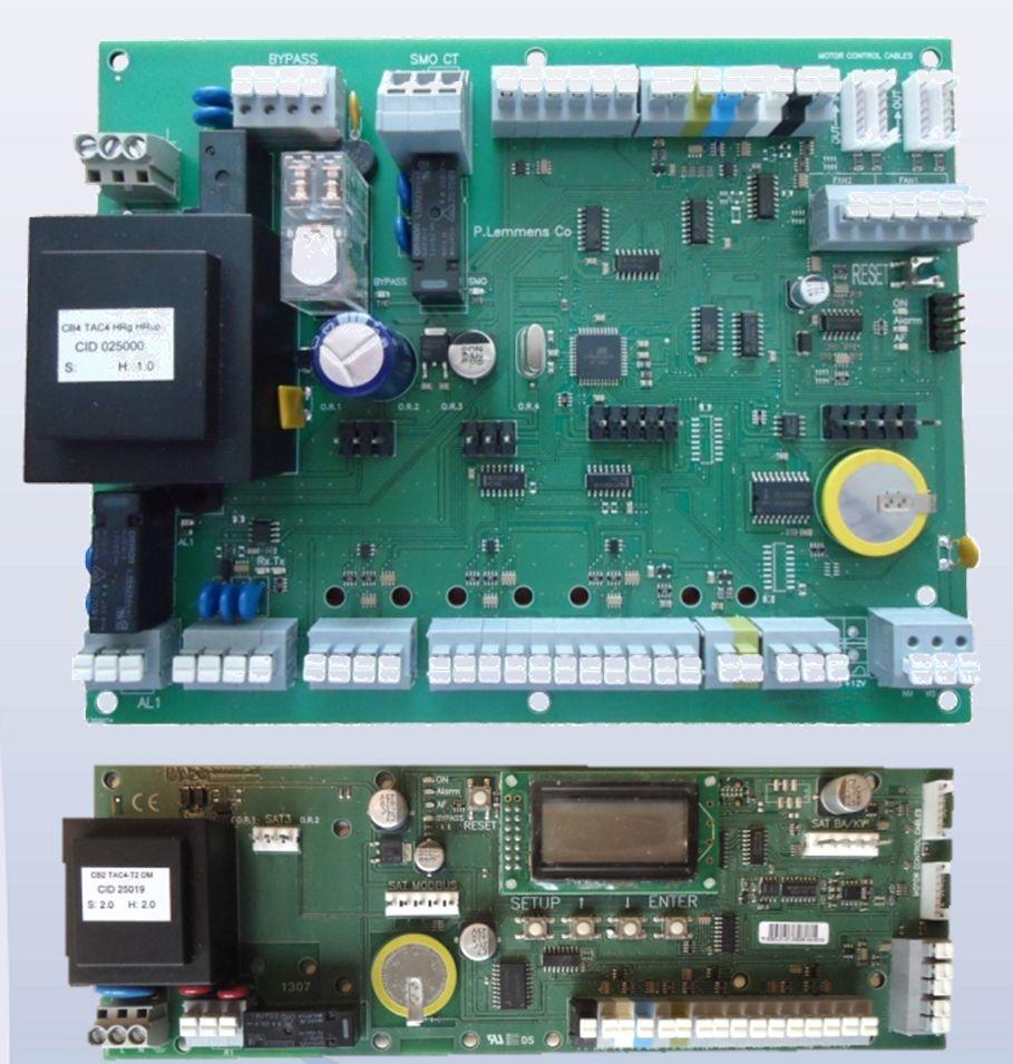
11 Installation and user s manual TAC5 + KNX 3. WIRING OF SAT KNX Just switch off and plug the SAT KNX on the «MODBUS» connector on the TAC5 board (figure 4). Warning: plugging the SAT KNX in the wrong connector on the TAC5 board can be fatal to both circuits! TAC5 DG/DT TAC5 DM/SC/F Figure 4 - Plugging of SAT KNX on the TAC5 control board 9
12 Then, connect the SAT KNX to the KNX network as shown in figure 5 and in respect with the KNX TP network specification (see point 4).. Figure 5 Wiring to the KNX Network 4. GROUP OBJECTS OF THE SAT KNX MODULE The group objects of SAT KNX are categories sets. One set of categories is dedicated to TAC5 DG, DM and DT controls, the other to TAC5 SC and F. The data flow direction is given by I (Input) or O (Output): 4.1 Group objects categories for TAC5 DG, DM and DT Drive Category for TAC5 DG, DM and DT The SAT KNX group objects of the drive category are listed and detailed in table 1: N Name I/O Size Type (DPT) Flags CRWTU Function Pilot - Main switch Switch I 1 bit DPT C-W-U Turn fans on or off. If turned on and group object <Airflow - Supply flow - Value> or <Airflow - Exhaust flow - Value> is set to a value > 0, then the fans are started in 'constant airflow' mode. If turned on and group objects <Airflow - Supply flow - Value> and <Airflow - Exhaust flow - Value> are set to 0, then the fans are started in the mode that is configured. The intention is to control the HVAC using one of the following group objects: use <Pilot - Main switch - Switch> or <Pilot - Fan speed 1 on/off - Switch>...<Pilot - Fan speed 3 on/off - Switch> or <Pilot - Speed % - Value> or <Pilot - Set Supply flow % - Value> and <Pilot - Set Exhaust flow % - Value> (using a mix might get confusing) Pilot - Main switch State O 1 bit DPT CR-T- Shows if HVAC unit is currently On or Off. 'On' means fans running. Is always sent on start up. Pilot - Fan speed 1 on/off - Switch I 1 bit DPT C-W-U Select fans speed 1. Writing value 1 activates speed 1 and resets the other <Pilot - Fan speed * on/off - Switch> group objects. Writing 0 stops fans. Pilot - Fan speed 2 on/off - Switch I 1 bit DPT C-W-U Select fans speed 2. Writing value 1 activates speed 2 and resets the other <Pilot - Fan speed * on/off - Switch> group objects. Writing 0 stops fans. Pilot - Fan speed 3 on/off - Switch I 1 bit DPT C-W-U Select fans speed 3. Writing value 1 activates speed 3 and resets the other <Pilot - Fan speed * on/off - Switch> group objects. Writing 0 stops fans. 10
13 Installation and user s manual TAC5 + KNX N Name I/O Size Type (DPT) Flags CRWTU Function Pilot - Fan speed 1 on/off - State O 1 bit DPT CR-T- Is 'On' if fans are running with speed 1 (LOW speed) Pilot - Fan speed 2 on/off - State O 1 bit DPT CR-T- Is 'On' if fans are running with speed 2 (MEDIUM speed) Pilot - Fan speed 3 on/off - State O 1 bit DPT CR-T- Is 'On' if fans are running with speed 3 (HIGH speed) Pilot - Speed % - Value I 1 byte DPT C-W-U Select fans speed with a percentage value. 0-9%: Fans OFF 40-69%: MEDIUM speed 10-39%: LOW speed %: HIGH speed Pilot - Speed % - State O 1 byte DPT CR-T- Shows the current fans speed as a percentage: 0% if fans are OFF, 33% for LOW speed, 66% for MEDIUM speed, 100% for HIGH speed. Pilot - Set Supply flow % - Value I 1 byte DPT C-W-U Set supply flow as % of the fan's max flow. This overrides the normal control via the viewer OFF/I/II/III buttons. If set: forces 'constant airflow' mode with independent airflow setpoints for supply and exhaust fans. If group object <Airflow - Supply flow - Value> or <Airflow - Exhaust flow - Value> is changed and either is set to a value > 0, then the 'constant airflow' mode is activated and the fans are started. If group object <Airflow - Supply flow - Value> or <Airflow - Exhaust flow - Value> is changed and both are set to 0, then the 'constant airflow' mode is terminated and the fans are stopped. Normal control via the viewer is resumed. (DPT 5.001: Value means %). Pilot - Set Supply flow % - State O 1 byte DPT CR-T- Feedback of group object <Airflow - Supply flow - Value> Pilot - Set Exhaust flow % - Value I 1 byte DPT C-W-U Set exhaust flow as % of the fan's max flow. This overrides the normal control via the viewer OFF/I/II/III buttons. If set: forces 'constant airflow' mode with independent airflow setpoints for supply and exhaust fans. If group object <Airflow - Supply flow - Value> or <Airflow - Exhaust flow - Value> is changed and either is set to a value > 0, then the 'constant airflow' mode is activated and the fans are started. If group object <Airflow - Supply flow - Value> or <Airflow - Exhaust flow - Value> is changed and both are set to 0, then the 'constant airflow' mode is terminated and the fans are stopped. Normal control via the viewer is resumed. (DPT 5.001: Value means %). Pilot - Set Exhaust flow % - State O 1 byte DPT CR-T- Feedback of group object <Airflow - Exhaust flow - Value> Pilot - Fans Running - State O 1 bit DPT CR-T- Shows that all fans (that should be running) are running. Is 1 (True) if fans are running. Is always sent on start up. Pilot - Working hours - State O 2 byte unsigned DPT CR-T- Shows the number of working hours of the fans hours. If the number of working hours internally is over hours, it will be reported as hours in KNX. Pilot - Reset working hours - Trigger I 1 bit DPT DPT_Reset C-W-U Reset Fans working hours to zero. 0 = no action. 1 = reset. Is turned off automatically. Pilot - Reset pending alarms - I 1 bit DPT C-W-U Trigger DPT_Reset Perform a RESET to clear pending alarms and resume normal working. 0 = no action. 1 = reset. Is turned off automatically. Pilot - Working mode - State O 1 byte DPT 5 CR-T- Value that shows the current working mode. This is an enumeration. Each value represents a certain working mode. 0 = Off (OFF) 1 = Constant airflow mode (CA) 2 = Linked system mode (LS) 3 = Constant air pressure mode (CPf) 4 = Constant air pressure mode with sensor (CPs) 5 = Initializing (INIT) 6 = Constant Torque mode (TQ) 7-255: reserved Table 1 SAT KNX Group objects Drive category for TAC5 DG, DM and DT 11
14 4.1.2 Mode and functions Category for TAC5 DG, DM and DT The SAT KNX group objects of the Mode and functions category are listed and detailed in table 2: N Name I/O Size Type (DPT) Flags CRWTU Function CPs mode - Supply fan setpoint - Value I 2 byte float DPT C-W-U Set voltage setpoint for CPs mode for the supply fans. Range mv. (voltage is internally stored with 0.1V resolution) CPs mode - Supply fan setpoint - State O 2 byte float DPT CR-T- Feedback of group object <CPs mode - Supply fan setpoint - Value> CPs mode - Exhaust fan setpoint - Value I 2 byte float DPT C-W-U Set voltage setpoint for CPs mode for the exhaust fans. Range mv. (voltage is internally stored with 0.1V resolution) CPs mode - Exhaust fan setpoint - State O 2 byte float DPT CR-T- Feedback of group object <CPs mode - Exhaust fan setpoint - Value> Operation mode - Automatic on/off - Switch I 1 bit DPT C-W-U Turn 'automatic' mode on or off. In automatic mode, the HVAC is controlled using a timetable. Automatic mode can only be used if a timetable is configured. Operation mode - Automatic on/off - State O 1 bit DPT CR-T- Shows if 'automatic' mode is on Operation mode - Boost on/off - Switch I 1 bit DPT C-W-U Force boost mode on (high air flow). Operation mode - Boost on/off - State O 1 bit DPT CR-T- Shows if boost mode is on Bypass function - Force bypass on - Switch I 1 bit DPT C-W-U Force the bypass on (valve open or heat wheel stop). Normally, the bypass is controlled automatically. When this group object is set to 'on' the bypass function is forced on. Bypass function - Force bypass on - State O 1 bit DPT CR-T- Feedback of group object <Bypass function - Force on - Switch> Bypass function - Bypass on/off - State O 1 bit DPT CR-T- Shows if the bypass is on (valve open or heatwheel stop) or off. If the bypass valve is partially open, its status is reported as 'on'. While the bypass valve is opening, the status is reported as 'on'. While the bypass valve is closing, the status is reported as 'off'. Air inlet function - Valve open/close - State O 1 bit DPT CR-T- Shows the status of the air inlet valve (CT-in option). (0=open, 1=closed) While the valve is opening, the status is reported as 'open'. While the valve is closing, the status is reported as 'closed'. MK3 function - MK3 on/off - Switch I 1 bit DPT C-W-U Force activation of MK3 (mixing cabinet). When this group object is set to 'on' the MK3 function is forced active. MK3 function - Current Status - State O 1 bit DPT CR-T- Shows if the MK3 function is on. During the switchover from off to on, the status is reported as 'on'. During the switchover from on to off, the status is reported as 'off'. Table 2 SAT KNX Group objects Mode and Function category for TAC5 DG, DM and DT 12
15 Installation and user s manual TAC5 + KNX Flow, Pressure, Voltage, Temperature Category for TAC5 DG, DM and DT The SAT KNX group objects of the Flow, Pressure, Voltage, Temperature category are listed and detailed in table 3: N Name I/O Size Type (DPT) Flags CRWTU Function Airflow - Ratio exhaust/supply flow Value I 1 byte DPT C-W-U DPT_Percent_U8 Set the desired exhaust flow / supply flow ratio. Range %. (DPT 5.004: Value means %) Airflow - Ratio exhaust/supply flow State O 1 byte DPT CR-T- DPT_Percent_U8 Shows the configured exhaust flow / supply flow ratio. Range %. If the ratio is configured > 255% it will be reported as 255% in KNX. Airflow - Sleep mode - Value I 1 byte DPT C-W-U Set the desired sleep mode airflow reduction percentage. Range %. (this value is internally stored with 1% resolution) (DPT 5.001: Value means %) Airflow - Sleep mode - State O 1 byte DPT CR-T- Shows the configured sleep mode airflow reduction percentage. Range %. Fan 1 - Current airflow - State O 2 byte float DPT CR-T- Shows the current airflow of fan 1. Range m3/h. Transmission rate is controlled by parameter <Minimum time until next current airflow or air pressure transmission>. Fan 1 - Current airpressure - State O 2 byte float DPT CR-T- Shows the current airpressure on fan 1. Range Pa. Transmission rate is controlled by parameter <Minimum time until next current airflow/airpressure/torque transmission>. Fan 2 - Current airflow - State O 2 byte float DPT CR-T- Shows the current airflow of fan 2. Range m3/h. Transmission rate is controlled by parameter <Minimum time until next current airflow/airpressure/torque transmission>. Fan 2 - Current airpressure - State O 2 byte float DPT CR-T- Shows the current airpressure on fan 2. Range Pa. Transmission rate is controlled by parameter <Minimum time until next current airflow/airpressure/torque transmission>. Fan 3 - Current airflow - State O 2 byte float DPT CR-T- Shows the current airflow of fan 3. Range m3/h. Transmission rate is controlled by parameter <Minimum time until next current airflow/airpressure/torque transmission>. Fan 3 - Current airpressure - State O 2 byte float DPT CR-T- Shows the current airpressure on fan 3. Range Pa. Transmission rate is controlled by parameter <Minimum time until next current airflow/airpressure/torque transmission>. Fan 4 - Current airflow - State O 2 byte float DPT CR-T- Shows the current airflow of fan 4. Range m3/h. Transmission rate is controlled by parameter <Minimum time until next current airflow/airpressure/torque transmission>. Fan 4 - Current airpressure - State O 2 byte float DPT CR-T- Shows the current airpressure on fan 4. Range Pa. Transmission rate is controlled by parameter <Minimum time until next current airflow/airpressure/torque transmission>. Supply fan - Current flow setpoint - State O 2 byte float DPT CR-T- Shows the current flow setpoint of the supply fans. Range m3/h. One of these (m3/h, Pa or mv) will be used. The others will be 0. Transmission rate is controlled by parameter <Minimum time until next fan setpoint transmission>. Supply fan - Current pressure setpoint - State O 2 byte float DPT CR-T- Shows the current pressure setpoint of the supply fans. Range Pa. One of these (m3/h, Pa or mv) will be used. The others will be 0. Transmission rate is controlled by parameter <Minimum time until next fan setpoint transmission>. Supply fan - Current voltage setpoint - State O 2 byte float DPT CR-T- Shows the current voltage setpoint of the supply fans. Range mv. One of these (m3/h, Pa or mv) will be used. The others will be 0. Transmission rate is controlled by parameter <Minimum time until next fan setpoint transmission>. Exhaust fan - Current flow setpoint - State O 2 byte float DPT CR-T- Shows the current flow setpoint of the exhaust fans. Range m3/h. One of these (m3/h, Pa or mv) will be used. The others will be 0. Transmission rate is controlled by parameter <Minimum time until next fan setpoint transmission>. Exhaust fan - Current pressure setpoint - State Shows the current pressure setpoint of the exhaust fans. Range Pa. One of these (m3/h, Pa or mv) will be used. The others will be 0. O 2 byte float DPT CR-T- 13
16 N Name I/O Size Type (DPT) Flags CRWTU Function Transmission rate is controlled by parameter <Minimum time until next fan setpoint transmission>. Exhaust fan - Current voltage setpoint - O 2 byte float DPT CR-T- State Shows the current voltage setpoint of the exhaust fans. Range mv. One of these (m3/h, Pa or mv) will be used. The others will be 0. Transmission rate is controlled by parameter <Minimum time until next fan setpoint transmission>. Temperature - T1 - State O 2 byte float DPT CR-T- Shows the T1 temperature, in C. Transmission rate is controlled by parameter <Minimum time until next current temperature transmission>. Temperature - T2 - State O 2 byte float DPT CR-T- Shows the T2 temperature, in C. Transmission rate is controlled by parameter <Minimum time until next current temperature transmission>. Temperature - T3 State O 2 byte float DPT CR-T- Shows the T3 temperature, in C. Transmission rate is controlled by parameter <Minimum time until next current temperature transmission>. Temperature T4 State O 2 byte float DPT CR-T- Shows the T4 temperature, in C. Transmission rate is controlled by parameter <Minimum time until next current temperature transmission>. Temperature - T5 State O 2 byte float DPT CR-T- Shows the T5 temperature, in C. Transmission rate is controlled by parameter <Minimum time until next current temperature transmission>. Temperature T7 State O 2 byte float DPT CR-T- Shows the T7 temperature, in C. Transmission rate is controlled by parameter <Minimum time until next current temperature transmission>. Temperature T8 - State O 2 byte float DPT CR-T- Shows the T8 temperature, in C. Transmission rate is controlled by parameter <Minimum time until next current temperature transmission>. Table 3 SAT KNX Group objects Flow, Pressure, Voltage, Temperature category for TAC5 DG, DM and DT Heat/Cool exchanger Category for TAC5 DG, DM and DT The SAT KNX group objects of the Heat/Cool exchanger category are listed and detailed in table 4: N Name I/O Size Type (DPT) Flags (CRWTU) Function Postheating - On/Off - Switch I 1 bit DPT C-W-U Switch the postheating on or off. Normally, postheating is enabled. Then it is controlled automatically. Postheating can be switched off by setting this group object to 'Off'. Postheating - On/Off - State O 1 bit DPT CR-T- Feedback of group object <Postheating - On/Off - Switch> Postheating - Temperature setpoint - Value I 2 byte float DPT C-W-U Sets the desired postheating temperature. In degrees Celsius. Range ,9 C. Postheating - Temperature setpoint - State O 2 byte float DPT CR-T- Feedback of group object <Postheating - Temperature setpoint - Value> Postcooling - On/Off - Switch I 1 bit DPT C-W-U Switch the postcooling on or off. Normally, postcooling is enabled. Then it is controlled automatically. Postcooling can be switched off by setting this group object to 'Off'. Postcooling - On/Off - State O 1 bit DPT CR-T- Feedback of group object <Postcooling - On/Off - Switch> Postcooling - Temperature setpoint - Value I 2 byte float DPT C-W-U Sets the desired postcooling temperature. In degrees Celsius. Range ,9 C. Postcooling - Temperature setpoint - State O 2 byte float DPT CR-T- Feedback of group object <Postcooling - Temperature setpoint - Value> Postheating/Postcooling - Antifreeze on/off - State O 1 bit DPT CR-T- Shows if the antifreeze for the external postheating (BA+) or postcooling (BA-) units is activated. Postheating/Postcooling - Heating/Cooling - Switch I 1 bit DPT C-W-U DPT_Heat/Cool Selects 'heating' or 'cooling'. 0 = cooling. 1 = heating. If 'cooling' is selected, cooling is enabled and heating is disabled. If 'heating' is selected, heating is enabled and cooling is disabled. 14
17 Installation and user s manual TAC5 + KNX N Name I/O Size Type (DPT) Flags (CRWTU) Function Postheating/Postcooling- Heating/Cooling - State O 1 bit DPT CR-T- DPT_Heat/Cool Shows if heating or cooling is selected. 0 = cooling. 1 = heating. Postheating/Postcooling - On/Off - State O 1 bit DPT CR-T- Shows if heating or cooling is on. Postheating/Postcooling - Current setpoint - State O 2 byte float DPT CR-T- Shows the current setpoint for heating/cooling setpoint temperature. Range C. Heat exchanger - Antifreeze on/off - State O 1 bit DPT CR-T- Shows if the antifreeze for the internal heat exchanger or NV is activated. Freecooling - Temperature setpoint - Value I 2 byte float DPT C-W-U Sets the desired freecooling temperature. In degrees Celsius. Range ,9 C. Freecooling - Temperature setpoint State O 2 byte float DPT CR-T- Feedback of group object <Freecooling - Temperature setpoint - Value> Table 4 SAT KNX Group objects Heat/Cool exchanger category for TAC5 DG, DM and DT Alarms Category for TAC5 DG, DM and DT The SAT KNX group objects of the Alarms category are listed and detailed in table 5: N Name I/O Size Type (DPT) Flags CRWTU Function Alarm - Pressure - Trigger I 1 bit DPT C-W-U Force a pressure alarm. Intended for external overpressure detector. 0 = no alarm. 1 = alarm. Alarm - Fire - Trigger I 1 bit DPT C-W-U Set the fire alarm on. Intended for external fire alarm I. 0 = no alarm. 1 = alarm. Alarm - State O 1 bit DPT CR-T- Shows that an alarm (non-fatal or fatal) is pending. 0 = no alarm, 1 = alarm. Alarm number is in group object <Alarm - Number - State> Is always sent on start up. Alarm - Fatal - State O 1 bit DPT CR-T- Shows that a fatal alarm is pending. Ventilation is stopped. 0 = no alarm, 1 = alarm. Alarm number is in group object <Alarm - Number - State> Is always sent on start up. Alarm - Number - State O 1 byte DPT 5 CR-T- Value that shows the pending alarm. This is an enumeration. Each value represents a certain alarm. 0 = No alarm 1 = Software alarm: The program code in flash has a checksum error, or the configuration data in eeprom has a checksum error. Fatal. 2 = Fan alarm: a fan is defective. Fatal. 3 = Pressure alarm: overpressure. 4 = T sensor alarm: a temperature sensor is defective. Fatal. 5 = Setpoint alarm: can t reach the requested setpoint. 6 = Service warning alarm. 7 = Stop-for-service alarm. Fatal. 8 = Fire Alarm. Fatal. 9 = Antifrost alarm: in antifreeze mode. 10 = Condensate drain pan is full. 11 = Comfort temperature alarm (postheating, postcooling) 12 = Heatwheel speed. Fatal. 13 = Modulating bypass position alarm. Fatal. 14 = SAT-BA module does not respond. Fatal : reserved. Is always sent on start up. Table 5 SAT KNX Group objects Alarms category for TAC5 DG, DM and DT 15
18 4.1.6 Analogue Input/Output Category for TAC5 DG, DM and DT The SAT KNX group objects of the Analogue Input/Output category are listed and detailed in table 6: N Name I/O Size Type (DPT) Flags CRWTU Function Analog input - K2 State O 1 byte DPT CR-T- Shows the actual level on analogue input K2. Range %. (DPT 5.001: Value means %). Transmission rate is controlled by parameter <Minimum time until next input status transmission>. Analog input - K3 State O 1 byte DPT CR-T- Shows the actual level on analogue input K3. Range %. (DPT 5.001: Value means %). Transmission rate is controlled by parameter <Minimum time until next input status transmission>. Analog output - OUT1 - State O 1 byte DPT CR-T- Shows the actual level on analogue output OUT1. In %. (DPT 5.001: Value means %). Transmission rate is controlled by parameter <Minimum time until next output status transmission>. Analog output - OUT4 - State O 1 byte DPT CR-T- Shows the actual level on analogue output OUT4. In %. (DPT 5.001: Value means %). Transmission rate is controlled by parameter <Minimum time until next output status transmission>. Analog output - OUT7 - State O 1 byte DPT CR-T- Shows the actual level on analogue output OUT7. In %. (DPT 5.001: Value means %). Transmission rate is controlled by parameter <Minimum time until next output status transmission>. Analog output - OUT8 - State O 1 byte DPT CR-T- Shows the actual level on analogue output OUT8. In %. (DPT 5.001: Value means %). Transmission rate is controlled by parameter <Minimum time until next output status transmission>. Analog output - KWin - State O 1 byte DPT CR-T- Shows the actual level on analogue output KWin. In %. (DPT 5.001: Value means %). Transmission rate is controlled by parameter <Minimum time until next output status transmission>. Analog output - KWout - State O 1 byte DPT CR-T- Shows the actual level on analogue output KWout. In %. (DPT 5.001: Value means %). Transmission rate is controlled by parameter <Minimum time until next output status transmission>. Analog output - KWext - State O 1 byte DPT CR-T- Shows the actual level on analogue output KWext. In %. (DPT 5.001: Value means %). Transmission rate is controlled by parameter <Minimum time until next output status transmission>. Bypass% - Position - State O 1 byte DPT CR-T- Shows the position of the proportional bypass valve. 0% means closed, 100% means fully open. (DPT 5.001: Value means %). Transmission rate is controlled by parameter <Minimum time until next output status transmission>. Table 6 SAT KNX Group objects Analogue Input/Output category for TAC5 DG, DM and DT 16
19 Installation and user s manual TAC5 + KNX Constant Torque Category for TAC5 DG, DM and DT The SAT KNX group objects of the Constant Torque category are listed and detailed in table 7: N Name I/O Size Type (DPT) Flags CRWTU Function Fan 1 - Current torque - State Output 1 byte DPT CR-T- Shows the torque on fan 1. Range %. Transmission rate is controlled by parameter <Minimum time until next current airflow or air pressure transmission>. Fan 2 - Current torque - State Output 1 byte DPT CR-T- Shows the torque on fan 2. Range %. Transmission rate is controlled by parameter <Minimum time until next current airflow or air pressure transmission>. Fan 3 - Current torque - State Output 1 byte DPT CR-T- Shows the torque on fan 3. Range %. Transmission rate is controlled by parameter <Minimum time until next current airflow or air pressure transmission>. Fan 4 - Current torque - State Output 1 byte DPT CR-T- Shows the torque on fan 4. Range %. Transmission rate is controlled by parameter <Minimum time until next current airflow or air pressure transmission>. Table 7 SAT KNX Group objects Constant Torque category for TAC5 DG, DM and DT 17
20 4.2 Group objects categories for TAC5 SC, F The categories are presented with the hypothesis that two fans are presents. If only one fan is present, only the objects referred to fan 1 should be considered Drive Category for TAC5 SC, F The SAT KNX group objects of the drive category are listed and detailed in table 8: N Name I/O Size Type (DPT) Flags CRWTU Function Pilot - Main switch Switch I 1 bit DPT C-W-U Turn fans on or off. If turned on and group object <Airflow Fan 1 flow - Value> or <Airflow Fan 2 flow - Value> is set to a value > 0, then the fans are started in 'constant airflow' mode. If turned on and group objects <Airflow Fan 1 flow - Value> and <Airflow Fan 2 flow - Value> are set to 0, then the fans are started in the mode that is configured. The intention is to control the HVAC using one of the following group objects: use <Pilot - Main switch - Switch> or <Pilot - Fan speed 1 on/off - Switch>.<Pilot - Fan speed 3 on/off - Switch> or <Pilot - Speed % - Value> or <Pilot - Set Fan 1 flow % - Value> and <Pilot - Set Fan 2 flow % - Value> (using a mix might get confusing) Pilot - Main switch State O 1 bit DPT CR-T- Shows if HVAC unit is currently On or Off. 'On' means fans running. Is always sent on start up. Pilot - Fan speed 1 on/off - Switch I 1 bit DPT C-W-U Select fans speed 1. Writing value 1 activates speed 1 and resets the other <Pilot - Fan speed * on/off - Switch> group objects. Writing 0 stops fans. Pilot - Fan speed 2 on/off - Switch I 1 bit DPT C-W-U Select fans speed 2. Writing value 1 activates speed 2 and resets the other <Pilot - Fan speed * on/off - Switch> group objects. Writing 0 stops fans. Pilot - Fan speed 3 on/off - Switch I 1 bit DPT C-W-U Select fans speed 3. Writing value 1 activates speed 3 and resets the other <Pilot - Fan speed * on/off - Switch> group objects. Writing 0 stops fans. Pilot - Fan speed 1 on/off - State O 1 bit DPT CR-T- Is 'On' if fans are running with speed 1 (LOW speed) Pilot - Fan speed 2 on/off - State O 1 bit DPT CR-T- Is 'On' if fans are running with speed 2 (MEDIUM speed) Pilot - Fan speed 3 on/off - State O 1 bit DPT CR-T- Is 'On' if fans are running with speed 3 (HIGH speed) Pilot - Speed % - Value I 1 byte DPT C-W-U Select fans speed with a percentage value. 0-9%: Fans OFF 40-69%: MEDIUM speed 10-39%: LOW speed %: HIGH speed Pilot - Speed % - State O 1 byte DPT CR-T- Shows the current fans speed as a percentage: 0% if fans are OFF, 33% for LOW speed, 66% for MEDIUM speed, 100% for HIGH speed. Pilot - Set Fan 1 flow % - Value I 1 byte DPT C-W-U Set fan 1 flow as % of the fan's max flow. This overrides the normal control via the viewer OFF/I/II/III buttons. If set: forces 'constant airflow' mode with independent airflow setpoints for fans 1 and 2. If group object <Airflow Fan 1 flow - Value> or <Airflow Fan 2 flow - Value> is changed and either is set to a value > 0, then the 'constant airflow' mode is activated and the fans are started. If group object <Airflow Fan 1 flow - Value> or <Airflow Fan 2 flow - Value> is changed and both are set to 0, then the 'constant airflow' mode is terminated and the fans are stopped. Normal control via the viewer is resumed. (DPT 5.001: Value means %). Pilot - Set Fan 1 flow % - State O 1 byte DPT CR-T- Feedback of group object <Airflow Fan 1 flow - Value> Pilot - Set Fan 2 flow % - Value I 1 byte DPT C-W-U 18
21 Installation and user s manual TAC5 + KNX N Name I/O Size Type (DPT) Flags CRWTU Function Set fan 2 flow as % of the fan's max flow. This overrides the normal control via the viewer OFF/I/II/III buttons. If set: forces 'constant airflow' mode with independent airflow setpoints for fans 1 and 2. If group object <Airflow Fan 1 flow - Value> or <Airflow Fan 2 flow - Value> is changed and either is set to a value > 0, then the 'constant airflow' mode is activated and the fans are started. If group object <Airflow Fan 1 flow - Value> or <Airflow Fan 2 flow - Value> is changed and both are set to 0, then the 'constant airflow' mode is terminated and the fans are stopped. Normal control via the viewer is resumed. (DPT 5.001: Value means %). Pilot - Set Fan 2 flow % - State O 1 byte DPT CR-T- Feedback of group object <Airflow Fan 2 flow - Value> Pilot - Fans Running - State O 1 bit DPT CR-T- Shows that all fans (that should be running) are running. Is 1 (True) if fans are running. Is always sent on start up. Pilot - Working hours - State O 2 byte DPT CR-Tunsigned Shows the number of working hours of the fans hours. If the number of working hours internally is over hours, it will be reported as hours in KNX. Pilot - Reset working hours - Trigger I 1 bit DPT C-W-U DPT_Reset Reset Fans working hours to zero 0 = no action. 1 = reset. Is turned off automatically. Pilot - Reset pending alarms - Trigger I 1 bit DPT C-W-U DPT_Reset Perform a RESET to clear pending alarms and resume normal working. 0 = no action. 1 = reset. Is turned off automatically. Pilot - Working mode - State O 1 byte DPT 5 CR-T- Value that shows the current working mode. This is an enumeration. Each value represents a certain working mode. 0 = Off (OFF) 1 = Constant airflow mode (CA) 2 = Linked system mode (LS) 3 = Constant air pressure mode (CPf) 4 = Constant air pressure mode with sensor (CPs) 5 = Initializing (INIT) 6 = Constant Torque mode (TQ) 7-255: reserved Table 8 SAT KNX Group objects Drive category for TAC5 SC, F Mode and functions Category for TAC5 SC, F N The SAT KNX group objects of the Mode and functions category are listed and detailed in table 9: Name I/O Size Type (DPT) Flags CRWTU Function CPs mode Fan 1 setpoint - Value I 2 byte float DPT C-W-U Set voltage setpoint for CPs mode for fan 1. Range mv. (voltage is internally stored with 0.1V resolution) CPs mode Fan 1 setpoint State O 2 byte float DPT CR-T- Feedback of group object <CPs mode Fan 1 setpoint - Value> CPs mode Fan 2 setpoint Value [TAC5 F] I 2 byte float DPT C-W-U Set voltage setpoint for CPs mode for fan 2. Range mv. (voltage is internally stored with 0.1V resolution) CPs mode Fan 2 setpoint State [TAC5 F] O 2 byte float DPT CR-T- Feedback of group object <CPs mode Fan 2 setpoint - Value> CPf mode Fan 1 setpoint - Value I 2 byte float DPT C-W-U Set the pressure setpoint for CPf mode for Fan 1. Range Pa. (pressure is internally stored with 1Pa resolution) CPf mode Fan 1 setpoint State O 2 byte float DPT CR-T- Feedback of group object <CPf mode Fan 1 setpoint - Value> CPf mode Fan 2 setpoint Value [TAC5 F] I 2 byte float DPT C-W-U Set the pressure setpoint for CPf mode for fan 2. Range Pa. (pressure is internally stored with 1Pa resolution) CPf mode Fan 2 setpoint State [TAC5 F] O 2 byte float DPT CR-T- Feedback of group object <CPf mode Fan 2 setpoint - Value> 19
22 N Name I/O Size Type (DPT) Flags CRWTU Function Operation mode - Automatic on/off - Switch I 1 bit DPT C-W-U Turn 'automatic' mode on or off. In automatic mode, the HVAC is controlled using a timetable. Automatic mode can only be used if a timetable is configured. Operation mode - Automatic on/off State O 1 bit DPT CR-T- Shows if 'automatic' mode is on Operation mode - Boost on/off - Switch I 1 bit DPT C-W-U Force boost mode on (high air flow). Operation mode - Boost on/off State O 1 bit DPT CR-T- Shows if boost mode is on Air inlet function - Valve open/close - State O 1 bit DPT CR-T- Shows the status of the air inlet valve (CT-in option). (0=open, 1=closed) While the valve is opening, the status is reported as 'open'. While the valve is closing, the status is reported as 'closed'. MK3 function - MK3 on/off Switch [TAC5 SC] I 1 bit DPT C-W-U Force activation of MK3 (mixing cabinet). When this group object is set to 'on' the MK3 function is forced active. MK3 function - Current Status State [TAC5 SC] O 1 bit DPT CR-T- Shows if the MK3 function is on. During the switchover from off to on, the status is reported as 'on'. During the switchover from on to off, the status is reported as 'off'. Table 9 SAT KNX Group objects Mode and Function category for TAC5 SC, F Flow, Pressure, Voltage Category for TAC5 SC, F The SAT KNX group objects of the Flow, Pressure, Voltage, Temperature category are listed and detailed in table 10: N Name I/O Size Type (DPT) Flags CRWTU Function Airflow - Ratio fan 2/fan 1 flow Value I 1 byte DPT C-W-U DPT_Percent_U8 Set the desired fan 2 flow / fan 1 flow ratio. In configuration with 2 dependents fans. Range %. (DPT 5.004: Value means %) Airflow - Ratio fan 2/fan 1 flow State O 1 byte DPT CR-T- DPT_Percent_U8 Shows the configured fan 2 flow / fan 1 flow ratio. In configuration with 2 dependents fans. Range %. If the ratio is configured > 255% it will be reported as 255% in KNX. Airflow - Sleep mode - Value I 1 byte DPT C-W-U Set the desired sleep mode airflow reduction percentage. Range %. (this value is internally stored with 1% resolution) (DPT 5.001: Value means %) Airflow - Sleep mode - State O 1 byte DPT CR-T- Shows the configured sleep mode airflow reduction percentage. Range %. Fan 1 - Current airflow - State O 2 byte float DPT CR-T- Shows the current airflow of fan 1. Range m3/h. Transmission rate is controlled by parameter <Minimum time until next current airflow or air pressure transmission>. Fan 1 - Current airpressure - State O 2 byte float DPT CR-T- Shows the current airpressure on fan 1. Range Pa. Transmission rate is controlled by parameter <Minimum time until next current airflow/airpressure/torque transmission>. Fan 2 - Current airflow State O 2 byte float DPT CR-T- Shows the current airflow of fan 2. Range m3/h. Transmission rate is controlled by parameter <Minimum time until next current airflow/airpressure/torque transmission>. Fan 2 - Current airpressure - State O 2 byte float DPT CR-T- Shows the current airpressure on fan 2. Range Pa. Transmission rate is controlled by parameter <Minimum time until next current airflow/airpressure/torque transmission>. Fan 1 - Current flow setpoint - State O 2 byte float DPT CR-T- Shows the current flow setpoint of fan 1. Range m3/h. One of these (m3/h, Pa or mv) will be used. The others will be 0. 20
23 Installation and user s manual TAC5 + KNX Transmission rate is controlled by parameter <Minimum time until next fan setpoint transmission>. Fan 1 - Current pressure setpoint - State O 2 byte float DPT CR-T- Shows the current pressure setpoint of fan 1. Range Pa. One of these (m3/h, Pa or mv) will be used. The others will be 0. Transmission rate is controlled by parameter <Minimum time until next fan setpoint transmission>. Fan 1 - Current voltage setpoint - State O 2 byte float DPT CR-T- Shows the current voltage setpoint of fan 1. Range mv. One of these (m3/h, Pa or mv) will be used. The others will be 0. Transmission rate is controlled by parameter <Minimum time until next fan setpoint transmission>. Fan 2 - Current flow setpoint - State O 2 byte float DPT CR-T- Shows the current flow setpoint of fan 2. Range m3/h. One of these (m3/h, Pa or mv) will be used. The others will be 0. Transmission rate is controlled by parameter <Minimum time until next fan setpoint transmission>. Fan 2 - Current pressure setpoint State O 2 byte float DPT CR-T- [TAC5 F] Shows the current pressure setpoint of fan 2. Range Pa. One of these (m3/h, Pa or mv) will be used. The others will be 0. Transmission rate is controlled by parameter <Minimum time until next fan setpoint transmission>. Fan 2 - Current voltage setpoint State O 2 byte float DPT CR-T- [TAC5 F] Shows the current voltage setpoint of fan 2. Range mv. One of these (m3/h, Pa or mv) will be used. The others will be 0. Transmission rate is controlled by parameter <Minimum time until next fan setpoint transmission>. Temperature - T2 State [TAC5 SC] O 2 byte float DPT CR-T- Shows the T2 temperature, in C. Transmission rate is controlled by parameter <Minimum time until next current temperature transmission>. Temperature - T5 State [TAC5 SC] O 2 byte float DPT CR-T- Shows the T5 temperature, in C. Transmission rate is controlled by parameter <Minimum time until next current temperature transmission>. Temperature T7 State [TAC5 SC] O 2 byte float DPT CR-T- Shows the T7 temperature, in C. Transmission rate is controlled by parameter <Minimum time until next current temperature transmission>. Temperature T8 State [TAC5 SC] O 2 byte float DPT CR-T- Shows the T8 temperature, in C. Transmission rate is controlled by parameter <Minimum time until next current temperature transmission>. Table 10 SAT KNX Group objects Flow, Pressure, Voltage category for TAC5 SC, F Heat/Cool exchanger Category for TAC5 SC 11: N The SAT KNX group objects of the Heat/Cool exchanger category are listed and detailed in table Name I/O Size Type (DPT) Flags (CRWTU) Function Postheating - On/Off - Switch I 1 bit DPT C-W-U Switch the postheating on or off. Normally, postheating is enabled. Then it is controlled automatically. Postheating can be switched off by setting this group object to 'Off'. Postheating - On/Off - State O 1 bit DPT CR-T- Feedback of group object <Postheating - On/Off - Switch> Postheating - Temperature setpoint - Value I 2 byte float DPT C-W-U Sets the desired postheating temperature. In degrees Celsius. Range ,9 C. Postheating - Temperature setpoint - State O 2 byte float DPT CR-T- Feedback of group object <Postheating - Temperature setpoint - Value> Postcooling - On/Off - Switch I 1 bit DPT C-W-U Switch the postcooling on or off. Normally, postcooling is enabled. Then it is controlled automatically. Postcooling can be switched off by setting this group object to 'Off'. Postcooling - On/Off - State O 1 bit DPT CR-T- Feedback of group object <Postcooling - On/Off - Switch> Postcooling - Temperature setpoint - Value I 2 byte float DPT C-W-U Sets the desired postcooling temperature. In degrees Celsius. Range ,9 C. 21
24 N Name I/O Size Type (DPT) Flags (CRWTU) Function Postcooling - Temperature setpoint - State O 2 byte float DPT CR-T- Feedback of group object <Postcooling - Temperature setpoint - Value> Postheating/Postcooling - Antifreeze on/off - State O 1 bit DPT CR-T- Shows if the antifreeze for the external postheating (BA+) or postcooling (BA-) units is activated. Postheating/Postcooling - Heating/Cooling - Switch I 1 bit DPT C-W-U DPT_Heat/Cool Selects 'heating' or 'cooling'. 0 = cooling. 1 = heating. If 'cooling' is selected, cooling is enabled and heating is disabled. If 'heating' is selected, heating is enabled and cooling is disabled. Postheating/Postcooling- Heating/Cooling - State O 1 bit DPT CR-T- DPT_Heat/Cool Shows if heating or cooling is selected. 0 = cooling. 1 = heating. Postheating/Postcooling - On/Off - State O 1 bit DPT CR-T- Shows if heating or cooling is on. Postheating/Postcooling - Current setpoint - State O 2 byte float DPT CR-T- Shows the current setpoint for heating/cooling setpoint temperature. Range C. Table 11 SAT KNX Group objects Heat/Cool exchanger category for TAC5 SC Alarms Category for TAC5 SC, F The SAT KNX group objects of the Alarms category are listed and detailed in table 12: N Name I/O Size Type (DPT) Flags CRWTU Function Alarm - Pressure - Trigger I 1 bit DPT C-W-U Force a pressure alarm. Intended for external overpressure detector. 0 = no alarm. 1 = alarm. Alarm - Fire - Trigger I 1 bit DPT C-W-U Set the fire alarm on. Intended for external fire alarm I. 0 = no alarm. 1 = alarm. Alarm - State O 1 bit DPT CR-T- Shows that an alarm (non-fatal or fatal) is pending. 0 = no alarm, 1 = alarm. Alarm number is in group object <Alarm - Number - State> Is always sent on start up. Alarm - Fatal - State O 1 bit DPT CR-T- Shows that a fatal alarm is pending. Ventilation is stopped. 0 = no alarm, 1 = alarm. Alarm number is in group object <Alarm - Number - State> Is always sent on start up. Alarm - Number - State O 1 byte DPT 5 CR-T- Value that shows the pending alarm. This is an enumeration. Each value represents a certain alarm. 0 = No alarm 1 = Software alarm: The program code in flash has a checksum error, or the configuration data in eeprom has a checksum error. Fatal. 2 = Fan alarm: a fan is defective. Fatal. 3 = Pressure alarm: overpressure. 4 = Not used. 5 = Setpoint alarm: can t reach the requested setpoint. 6 = Service warning alarm. 7 = Stop-for-service alarm. Fatal. 8 = Fire Alarm. Fatal. 9 = Not used. 10 = Not used. 11 = Comfort temperature alarm (postheating, postcooling) [TAC5 SC] 12 = Not used. 13 = Not used. 14 = SAT-BA module does not respond. Fatal. [TAC5 SC] : reserved. Is always sent on start up. Table 12 SAT KNX Group objects Alarms category for TAC5 SC, F 22
25 Installation and user s manual TAC5 + KNX Analogue Input/Output Category for TAC5 SC, F The SAT KNX group objects of the Analogue Input/Output category are listed and detailed in table 13: N Name I/O Size Type (DPT) Flags CRWTU Function Analog input - K2 State O 1 byte DPT CR-T- Shows the actual level on analogue input K2. Range %. (DPT 5.001: Value means %). Transmission rate is controlled by parameter <Minimum time until next input status transmission>. Analog input - K3 State O 1 byte DPT CR-T- Shows the actual level on analogue input K3. Range %. (DPT 5.001: Value means %). Transmission rate is controlled by parameter <Minimum time until next input status transmission>. Analog output - OUT7 State [TAC5 SC] O 1 byte DPT CR-T- Shows the actual level on analogue output OUT7. In %. (DPT 5.001: Value means %). Transmission rate is controlled by parameter <Minimum time until next output status transmission>. Analog output - OUT8 State [TAC5 SC] O 1 byte DPT CR-T- Shows the actual level on analogue output OUT8. In %. (DPT 5.001: Value means %). Transmission rate is controlled by parameter <Minimum time until next output status transmission>. Analog output - KWext State [TAC5 SC] O 1 byte DPT CR-T- Shows the actual level on analogue output KWext. In %. (DPT 5.001: Value means %). Transmission rate is controlled by parameter <Minimum time until next output status transmission>. Table 13 SAT KNX Group objects Analogue Input/Output category for TAC5 SC, F Constant Torque Category for TAC5 SC, F The SAT KNX group objects of the Constant Torque category are listed and detailed in table 14: N Name I/O Size Type (DPT) Flags CRWTU Function Fan 1 - Current torque - State Output 1 byte DPT CR-T- Shows the torque on fan 1. Range %. Transmission rate is controlled by parameter <Minimum time until next current airflow or air pressure transmission>. Fan 2 - Current torque - State Output 1 byte DPT CR-T- Shows the torque on fan 2. Range %. Transmission rate is controlled by parameter <Minimum time until next current airflow or air pressure transmission>. Table 14 SAT KNX Group objects Constant Torque category for TAC5 SC, F 23
26 4.3 Control and optimization parameters of the KNX bus These parameters are not group objects and enable to control and to optimize the use of the KNX bus. They are listed in table 15: N Name Size /Type Default value Function Delay before sending group objects (0-255 sec) Byte 2 Delay before any group object is transmitted to the KNX bus after start up. Group objects are sent only if they change value. Range seconds. Maximum number of messages sent per second (1-255) Byte 10 To control KNX bus load. Limit the number of group objects transmitted per second. If the maximum number of messages sent per second is reached, further messages will be delayed until the next second. Range Minimum time until next fan setpoint transmission (0-255 sec) Byte 5 To control KNX bus load. Sometimes fan setpoint values may change frequently. This parameter defines a minimum delay time before the same group object is sent again. Range seconds. Minimum time until next current airflow/airpressure/torque transmission (0 - Byte sec) To control KNX bus load. The fan's current airflow and airpressure will change frequently. This parameter defines a minimum delay time before the same group object is sent again. Range seconds. Minimum time until next input status transmission (0-255 sec) Byte 5 To control KNX bus load. Sometimes input values (mainly analogue inputs) may change frequently. This parameter defines a minimum delay time before the same group object is sent again. Range seconds. Minimum time until next current temperature transmission (0-255 sec) Byte 30 To control KNX bus load. Sometimes temperature inputs may change frequently. This parameter defines a minimum delay time before the same group object is sent again. Range seconds. Minimum time until next output state transmission (0-255 sec) Byte 5 To control KNX bus load. Sometimes output values 'mainly analogue outputs) may change frequently. This parameter defines a minimum delay time before the same group object is sent again. Range seconds. Table 15 Control and Optimization parameters of the KNX bus 5. INTEGRATION OF THE SAT KNX IN A ETS PROJECT (4 OR MAJOR) The integration of the SAT KNX presumes and requires from the user the necessary knowledge of ETS software, version 4 or major provided by the KNX organization (see the site SAT KNX start up project Download from Lemmens website ( the last SAT KNX Starter project matching the control board of the unit and the software version installed on it. In fact, the SAT KNX project are differentiated by TAC control board (TAC5 DG, TAC5 DM, TAC5 DT, TAC5 SC and TAC5 F), by the software version installed on these boards and by the project version itself. The nomenclature of the projects on the site is as follows: Unless stated otherwise, select the file with the highest project version and with the regulation software version identical to the one running on the board. If no matching regulation software version is available, take the one directly below in the order of the revision number, then minor version and finally major version. 24
27 Installation and user s manual TAC5 + KNX Example: The installed unit on site is HR MURAL 450 with TAC5 DM control board where software version is running. The KNX Starter projects on the website are: - SAT KNX Starter_TAC5DG_ S P01 - SAT KNX Starter_TAC5DG_ S P02 - SAT KNX Starter_TAC5DG_ S P01 - SAT KNX Starter_TAC5DM_ S P01 - SAT KNX Starter_TAC5DM_ S P02 - SAT KNX Starter_TAC5DM_ S P01 - SAT KNX Starter_TAC5DT_ S P01 - SAT KNX Starter_TAC5DT_ S P01 SAT KNX Starter_TAC5DM_ S P02 project must be chosen. 5.2 Include the SAT KNX device in a ETS project Open the SAT KNX start up project with the ETS (version 4 or major) software and select the device «SAT KNX Lemmens» in the devices window. Add it then to the favourite. Open the KNX project wherein the SAT KNX must be included and select the SAT KNX Lemmens device in the Favourite windows. Copy the device and paste it in the topology window at the desired row. From now on, use the SAT KNX Lemmens device as any other KNX device with ETS. 5.3 SAT KNX Commissioning Once the project defined, the SAT KNX device can be commissioned by the ETS programming. Just push the SAT KNX programming button and the programming will begin. While programming, the red led will light. Figure 6 Programming Button Figure 7 Programming Led 25
28 6. KNX NETWORK SPECIFICATIONS The KNX communication is based on the reference model OSI which define 7 layers characterized by their own functionalities. The transmitted data go from the highest layer to the lowest, each layers adding its specific information to build what is called the PDU (Protocol Data Unit). The received data go from the lowest layer to the highest, each layer using and withdrawing the data that are necessary for it and that have been added by the corresponding layer during the transmission. The communication can be established in connected or unconnected mode. - Connected mode: the message transmitting part first establishes a logical link for the connection with the addressed part. This link will be maintained during the entire communication. - Unconnected mode: the transmitting part doesn t establish a connection and send its messages to all the devices on the network during the entire communication that will last until the addressed part acknowledges the messages that are destined for it. The 7 layers are listed here below with their description and implementation in KNX: 6.1 Layer 7 Application That is the application support for sending and receiving useful data. In KNX, that means on one side the use of the group object in the participating modules in unconnected communication mode, on the other side the building and treatment of the configuration messages («management service») which are sent to the modules during the commissioning phase in connected communication mode Application layer PDU - A_PDU The different types of A_PDU in function of the 2 first bits of the T_PDU (transport layer PDU) are detailed in annex Layer 6 Presentation Not implemented in KNX 6.3 Layer 5 Session Not implemented in KNX 6.4 Layer 4 Transport In unconnected mode Check the associations of the group objects in the bus devices with the group addresses: During the transmission: Ensure that the group address is sent with the value of the group object that has been modified During the reception: Ensure that the values of all group objects whose group address is associated to the one received are updated In connected mode To establish a communication in connected mode, the transmitter device will send a connection message using for destination address, the individual address of the receiving device. 26
29 Installation and user s manual TAC5 + KNX During the connected mode established communication, the transport layer of each component will use the «ACK» and «NACK» messages of the transport layer to acknowledge or reject messages. The rejected messages are repeated up to 3 times. The communication is monitored by timers. If a telegram cannot be transmitted between a certain time interval or if neither a «ACK» nor a «NACK» have been received by the other part, the established communication is broken. The connection is monitored by a sequence number that goes from 0 to 15 and if the sequence is not respected, the receiver will break the established communication Transport layer PDU - T_PDU La T_PDU contains : 2 bits to indicate the communication type at transport level (00=Unnumbered Data Packet- UDP, 01=Numbered Data Packet-NDP, 10=Unnumbered Control Data-UCD, 11=Numbered Control Data-NCD) 4 bits for the sequential number (only for «Numbered» communication type, otherwise meaningless and set to 0). The rest of the T_PDU is the A_PDU, Application PDU (see point 6.1.1). 6.5 Layer 3 Network Ensures the routing of the data through the network nodes which are interconnected by links. In a KNX network, the links are the segment while the nodes are the area and the line couplers. Loops between 2 lines are not allowed. The network layer will add to the transmitted telegram a routing counter whose value will be evaluated only by the network layer of the coupler and by the modules. For a value of 7, the telegram will always be routed to the receiving coupler. This value is allowed only for ETS. For a value from 1 to 6, the telegram will be routed by the coupler when: In connected mode: the individual address present in the telegram as destination address is the one of a component placed at the opposite side than the one of the line or the area of the receiving coupler. During routing, the coupler will decrement the value of the routing counter. In unconnected mode: the group address used in the telegram as destination address is inside its filter table. With a 0 value, the telegram will not be routed by the area or line coupler Network layer PDU - N_PDU The N_PDU is composed by the data of the network and the higher layers. The specific data for the network layer are represented by: - Tb (1 bit) : it is a bit that indicates that the address of the receiver of the layer 2 data link PDU must be interpreted as an individual address or as a group address (see point ). - Rb (3 bits) : routing counter. - Lb (4 bits) : useful length of the telegram - T_PDU: Transport PDU (see point 6.4.3). 6.6 Layer 2 Data link Ensures the transmission of a telegram between 2 network nodes. The errors control informations will be inserted at this level. 27
30 This layer ensures also the collisions control due to simultaneous transmission and uses here the CSMA/CA system (Carrier Sense Multiple Access with Collision Avoidance). The maximum delay for collision detection is 10 µs Data link PDU - L_PDU KNX telegram structure of the link layer (L_PDU) : Control field (8 bits) Source address (16 bits) Receiver address (16 bits) N_PDU 8 bits T_PDU 6 bits A_PDU Check field (8 bits) Control Field of the L_PDU Structure (D7 to D0 represent 1 bit and D0 is the first sent): D7 D6 D5 D4 D3 D2 D1 D0 1 0 /R 1 P P 0 0 The values 0 or 1 must be kept otherwise the telegram is rejected. D0 and D1 serve as preamble to the telegram and avoid interpreting the tension spikes as start bit. The 2 bits P set the priority (00= Priority 1-system functions; 10=Priority 2-alarms functions; 01=Priority 3-normal mode, high priority; 11=Priority 4-normal mode, low priority). This priority is referred to the ones defined at level 7 for group objects and is passed through the layers down to layer 2. The bit /R indicates that a telegram is repeated when its value is 0. The priority bits have this value because a telegram with the first bit to 0 has the priority in case of collision (see layer 1) Source address of the L_PDU It is the individual address of the transmitter device. Structure (D15 to D0 represent 1 bit and D0 is the first sent): D15 D14 D13 D12 D11 D10 D9 D8 D7 D6 D5 D4 D3 D2 D1 D0 Area 0=backbone 1 to 15=area Line 0=main line 1 to 15=line Device address 0=coupler 1 to 64=device >64=line extension, other line segment Receiver address of the L_PDU It can be either the group address (in unconnected mode) or the individual address (in connected mode) of the receiver device. The indication will be done on the first bit of the N_PDU field (see below). If this bit is 0, then the receiver address is its individual address and the structure is the same as the individual source address. If this bit is 1, then the receiver address is its group address (with 2 or 3 levels hierarchy) and the structure is the following (D15 to D0 represent 1 bit and D0 is the first sent): 28
31 Installation and user s manual TAC5 + KNX D15 D14 D13 D12 D11 D10 D9 D8 D7 D6 D5 D4 D3 D2 D1 D0 Main group Sub group Main group Middle group Sub group N_PDU field of the L_PDU See point Check field of the L_PDU The technic for the errors detection is the «Cross check» that is the combination between the vertical parity check (parity bit per character) and the horizontal parity check (a control character whose each bit value is the parity of the character obtained by taking the corresponding bits on each transmitted character) Telegrams acknowledge The telegrams acknowledge is also supported by the link layer. The bus device or the area/line coupler sends an acknowledge between a specified time («IACK», «INACK»). The «BUSY» acknowledge type controls the data flow. If the layer 2 of the emitter receives an INACK or BUSY message or an incorrect message or no IACK message, then it sends again the telegram. The repeated telegrams are marked with the bit 5 of the control field. 6.7 Layer 1 Physical This layer is concerned by the physical nature of the signal and converts the received bits of layer 2 in electrical signal in this case. The specifications and protocols of the media are supported by this layer. The KNX network uses a serial bus and a time multiplexing: TDM (Time Division Multiplexing). The data transmission type is the base band one where the binary information is transmitted as bipolar rectangular pulses for 0 bits, no pulse for 1 bits and this allows the collision detection during simultaneous transmission since a device will read a 0 on the bus while it is transmitting a 1. The binary signals shape is illustrated in figure 8. 29
32 Figure 8 KNX binary signals shape The bus device transmits a half wave (Va-Vb) and the other half wave is produced in great part with the supply coil and that explains the maximum distance of 350 m between device and supply. The transmission speed on the KNX bus is so of 1/104 µs = 9600 bit/s. For a KNX TP network (Twisted pair) used by this application, the physical layer is characterized as follows:. The network has one or several electrical segment with each one or two supplies but without line coupler.. Random topology. Total capacitance of a segment (measured at 10 KHz): Without bus device, line coupler, line repeater: 100 nf max With bus device, line coupler, line repeater: 120 nf max. Bus line resistance between supply and device, line coupler or repeater: 25 Ω max.. Bus line resistance between two devices, line coupler or repeater: 50 Ω max.. Minimum resistance between two supplies: 15 Ω.. Bus line minimum length between two supplies: 200 m.. Tension drop on bus line between supply and device or line coupler: 5 V.. Maximum length of a bus line segment: 1000 m. Maximum length between 2 devices: 700 m (due to maximum delay for the collision detection of 10 µs). Line maximum length between supply and device: 350 m. No terminal resistor needed.. The bus devices are fed with a supply of 24 V DC by the bus.. Maximum number of devices on a segment: 64. Figure 9 shows the dimension limitations of the KNX network: 30
33 Installation and user s manual TAC5 + KNX Figure 9 maximum dimensions in KNX network For more information, see the documentation provided by the KNX association on the web site 7. CABLE SPECIFICATIONS They result from the physical layer characteristics of the physical layer seen above. Use KNX green cable or a cable that match these criteria: Twisted pair, 2 pairs. Use one pair to connect and +. Load resistance per line: max 37 Ω/km (loop 74 Ω/km) Load capacitance per line: max 100 nf/km (800 Hz) Shielded Twist numbers: min. 5/m Section 0,5 mm² Place this cable far from power cable of the installation If the unit is installed outside, take care to use an adapted cable (weather and UV protected, ). 31
34 8. ANNEXES 8.1 Annex 1: Datapoints types Symbol A A[n] B C E F N r U V Z8 Field Character Character string Boolean / Bit set Control Exponent Float value enumerator Reserved bit or field Unsigned value 2 nd complement signed value Standardized status/b8 command. Encoded as DPT_StatusGen 32
35 Installation and user s manual TAC5 + KNX 8.2 Annex 2: most used datapoints DPT_ID Format DPT_Name B1 DPT_Switch B1 DPT_Bool B1 DPT_Enable B1 DPT_Ramp B1 DPT_Alarm B1 DPT_BinaryValue B1 DPT_Step B1 DPT_UpDown B1 DPT_OpenClose B1 DPT_Start B1 DPT_State B1 DPT_Invert B1 DPT_DimSendStyle B1 DPT_InputSource B1 DPT_Reset B1 DPT_Ack B1 DPT_Trigger B1 DPT_Occupancy B1 DPT_Window_Door B1 DPT_LogicalFunction B1 DPT_Scene_AB B1 DPT_ShutterBlinds_Mode B1 DPT_Heat/Cool B2 DPT_Switch_Control B2 DPT_Bool_Control B2 DPT_Enable_Control B2 DPT_Ramp_Control B2 DPT_Alarm_Control B2 DPT_BinaryValue_Control B2 DPT_Step_Control B2 DPT_Direction1_Control B2 DPT_Direction2_Control B2 DPT_Start_Control B2 DPT_State_Control B2 DPT_Invert_Control B1U3 DPT_Control_Dimming B1U3 DPT_Control_Blinds A8 DPT_Char_ASCII A8 DPT_Char_8859_ U U8 DPT_Angle U8 DPT_Percent_U U8 DPT_DecimalFactor U8 DPT_Tariff 33
36 DPT_ID Format DPT_Name U8 DPT_Value_1_Ucount V8 DPT_Percent_V V8 DPT_Value_1_Count B5N3 DPT_Status_Mode U16 DPT_Value_2_Ucount U16 DPT_TimePeriodMsec U16 DPT_TimePeriod10MSec U16 DPT_TimePeriod100MSec U16 DPT_TimePeriodSec U16 DPT_TimePeriodMin U16 DPT_TimePeriodHrs U16 DPT_PropDataType U16 DPT_Length_mm U16 DPT_UElCurrentmA U16 DPT_Brightness V16 DPT_Value_2_Count V16 DPT_DeltaTimeMsec V16 DPT_DeltaTime10MSec V16 DPT_DeltaTime100MSec V16 DPT_DeltaTimeSec V16 DPT_DeltaTimeMin V16 DPT_DeltaTimeHrs V16 DPT_Percent_V V16 DPT_Rotation_Angle F16 DPT_Value_Temp F16 DPT_Value_Tempd F16 DPT_Value_Tempa F16 DPT_Value_Lux F16 DPT_Value_Wsp F16 DPT_Value_Pres F16 DPT_Value_Humidity F16 DPT_Value_AirQuality F16 DPT_Value_Time F16 DPT_Value_Time F16 DPT_Value_Volt F16 DPT_Value_Curr F16 DPT_PowerDensity F16 DPT_KelvinPerPercent F16 DPT_Power F16 DPT_Value_Volume_Flow F16 DPT_Rain_Amount F16 DPT_Value_Temp_F F16 DPT_Value_Wsp_kmh N3N5r2N6r2N6 DPT_TimeOfDay r3n5r4n4r1u7 DPT_Date 34
37 Installation and user s manual TAC5 + KNX DPT_ID Format DPT_Name U32 DPT_Value_4_Ucount V32 DPT_Value_4_Count V32 DPT_ActiveEnergy V32 DPT_ApparantEnergy V32 DPT_ReactiveEnergy V32 DPT_ActiveEnergy_kWh V32 DPT_ApparantEnergy_kVAh V32 DPT_ReactiveEnergy_kVARh V32 DPT_LongDeltaTimeSec F32 DPT_Value_Acceleration F32 DPT_Value_Acceleration_Angular F32 DPT_Value_Activation_Energy F32 DPT_Value_Activity F32 DPT_Value_Mol F32 DPT_Value_Amplitude F32 DPT_Value_AngleRad F32 DPT_Value_AngleDeg F32 DPT_Value_Angular_Momentum F32 DPT_Value_Angular_Velocity F32 DPT_Value_Area F32 DPT_Value_Capacitance F32 DPT_Value_Charge_DensitySurface F32 DPT_Value_Charge_DensityVolume F32 DPT_Value_Compressibility F32 DPT_Value_Conductance F32 DPT_Value_Electrical_Conductivity F32 DPT_Value_Density F32 DPT_Value_Electric_Charge F32 DPT_Value_Electric_Current F32 DPT_Value_Electric_CurrentDensity F32 DPT_Value_Electric_DipoleMoment F32 DPT_Value_Electric_Displacement F32 DPT_Value_Electric_FieldStrength F32 DPT_Value_Electric_Flux F32 DPT_Value_Electric_FluxDensity F32 DPT_Value_Electric_Polarization F32 DPT_Value_Electric_Potential F32 DPT_Value_Electric_PotentialDifference F32 DPT_Value_ElectromagneticMoment F32 DPT_Value_Electromotive_Force F32 DPT_Value_Energy F32 DPT_Value_Force F32 DPT_Value_Frequency F32 DPT_Value_Angular_Frequency F32 DPT_Value_Heat_Capacity 35
38 DPT_ID Format DPT_Name F32 DPT_Value_Heat_FlowRate F32 DPT_Value_Heat_Quantity F32 DPT_Value_Impedance F32 DPT_Value_Length F32 DPT_Value_Light_Quantity F32 DPT_Value_Luminance F32 DPT_Value_Luminous_Flux F32 DPT_Value_Luminous_Intensity F32 DPT_Value_Magnetic_FieldStrength F32 DPT_Value_Magnetic_Flux F32 DPT_Value_Magnetic_FluxDensity F32 DPT_Value_Magnetic_Moment F32 DPT_Value_Magnetic_Polarization F32 DPT_Value_Magnetization F32 DPT_Value_MagnetomotiveForce F32 DPT_Value_Mass F32 DPT_Value_MassFlux F32 DPT_Value_Momentum F32 DPT_Value_Phase_AngleRad F32 DPT_Value_Phase_AngleDeg F32 DPT_Value_Power F32 DPT_Value_Power_Factor F32 DPT_Value_Pressure F32 DPT_Value_Reactance F32 DPT_Value_Resistance F32 DPT_Value_Resistivity F32 DPT_Value_SelfInductance F32 DPT_Value_SolidAngle F32 DPT_Value_Sound_Intensity F32 DPT_Value_Speed F32 DPT_Value_Stress F32 DPT_Value_Surface_Tension F32 DPT_Value_Common_Temperature F32 DPT_Value_Absolute_Temperature F32 DPT_Value_TemperatureDifference F32 DPT_Value_Thermal_Capacity F32 DPT_Value_Thermal_Conductivity F32 DPT_Value_ThermoelectricPower F32 DPT_Value_Time F32 DPT_Value_Torque F32 DPT_Value_Volume F32 DPT_Value_Volume_Flux F32 DPT_Value_Weight F32 DPT_Value_Work U4U4U4U4U4U4B4N4 DPT_Access_Data 36
39 Installation and user s manual TAC5 + KNX DPT_ID Format DPT_Name A112 DPT_String_ASCII A112 DPT_String_8859_ r2u6 DPT_SceneNumber B1r1U6 DPT_SceneControl U8[r4U4][r3U5][U3U5][r2U6][r2U6]B16 DPT_DateTime N8 DPT_SCLOMode N8 DPT_BuildingMode N8 DPT_OccMode N8 DPT_Priority N8 DPT_LightApplicationMode N8 DPT_ApplicationArea N8 DPT_AlarmClassType N8 DPT_PSUMode N8 DPT_ErrorClass_System N8 DPT_ErrorClass_HVAC N8 DPT_Time_Delay N8 DPT_Beaufort_Wind_Force_Scale N8 DPT_SensorSelect N8 DPT_FuelType N8 DPT_BurnerType N8 DPT_HVACMode N8 DPT_DHWMode N8 DPT_LoadPriority N8 DPT_HVACContrMode N8 DPT_HVACEmergMode N8 DPT_ChangeoverMode N8 DPT_ValveMode N8 DPT_DamperMode N8 DPT_HeaterMode N8 DPT_FanMode N8 DPT_MasterSlaveMode N8 DPT_StatusRoomSetp N8 DPT_Behaviour_Lock_Unlock N8 DPT_Behaviour_Bus_Power_Up_Down N8 DPT_CommMode N8 DPT_AddInfoTypes N8 DPT_RF_ModeSelect N8 DPT_RF_FilterSelect B8 DPT_StatusGen B8 DPT_Device_Control B8 DPT_ForceSign B8 DPT_ForceSignCool B8 DPT_StatusRHC B8 DPT_StatusSDHWC B8 DPT_FuelTypeSet 37
40 DPT_ID Format DPT_Name B8 DPT_StatusRCC B8 DPT_StatusAHU B8 DPT_RF_ModeInfo B8 DPT_RF_FilterInfo B8 DPT_Channel_Activation_ B16 DPT_StatusDHWC B16 DPT_StatusRHCC B16 DPT_Media B16 DPT_Channel_Activation_ N2 DPT_OnOff_Action N2 DPT_Alarm_Reaction N2 DPT_UpDown_Action N2 DPT_HVAC_PB_Action A[n] DPT_VarString_8859_ U4U4 DPT_DoubleNibble r1b1u6 DPT_SceneInfo B32 DPT_CombinedInfoOnOff A[n] DPT_UTF V64 DPT_ActiveEnergy_V V64 DPT_ApparantEnergy_V V64 DPT_ReactiveEnergy_V B24 DPT_Channel_Activation_ N3 DPT_PB_Action_HVAC_Extended B1Z8 DPT_Heat/Cool_Z B1Z8 DPT_BinaryValue_Z N8Z8 DPT_HVACMode_Z N8Z8 DPT_DHWMode_Z N8Z8 DPT_HVACContrMode_Z N8Z8 DPT_EnablH/Cstage_Z DPT_EnablH/CStage N8Z8 DPT_BuildingMode_Z N8Z8 DPT_OccMode_Z N8Z8 DPT_HVACEmergMode_Z U8Z8 DPT_RelValue_Z U8Z8 DPT_UCountValue8_Z U16Z8 DPT_TimePeriodMsec_Z U16Z8 DPT_TimePeriod10Msec_Z U16Z8 DPT_TimePeriod100Msec_Z U16Z8 DPT_TimePeriodSec_Z U16Z8 DPT_TimePeriodMin_Z U16Z8 DPT_TimePeriodHrs_Z U16Z8 DPT_UFlowRateLiter/h_Z U16Z8 DPT_UCountValue16_Z U16Z8 DPT_UElCurrentμA_Z U16Z8 DPT_PowerKW_Z U16Z8 DPT_AtmPressureAbs_Z 38
41 Installation and user s manual TAC5 + KNX DPT_ID Format DPT_Name U16Z8 DPT_PercentU16_Z U16Z8 DPT_HVACAirQual_Z U16Z8 DPT_WindSpeed_Z DPT_WindSpeed U16Z8 DPT_SunIntensity_Z U16Z8 DPT_HVACAirFlowAbs_Z V8Z8 DPT_RelSignedValue_Z V16Z8 DPT_DeltaTimeMsec_Z V16Z8 DPT_DeltaTime10Msec_Z V16Z8 DPT_DeltaTime100Msec_Z V16Z8 DPT_DeltaTimeSec_Z V16Z8 DPT_DeltaTimeMin_Z V16Z8 DPT_DeltaTimeHrs_Z V16Z8 DPT_TempHVACAbs_Z V16Z8 DPT_TempHVACRel_Z V16Z8 DPT_HVACAirFlowRel_Z U16N8 DPT_HVACModeNext U16N8 DPT_DHWModeNext U16N8 DPT_OccModeNext U16N8 DPT_BuildingModeNext U8B8 DPT_StatusBUC U8B8 DPT_LockSign U8B8 DPT_ValueDemBOC U8B8 DPT_ActPosDemAbs U8B8 DPT_StatusAct V16B8 DPT_StatusHPM V16B8 DPT_TempRoomDemAbs V16B8 DPT_StatusCPM V16B8 DPT_StatusWTC V16B16 DPT_TempFlowWaterDemAbs U8N8 DPT_EnergyDemWater V16V16V16 DPT_TempRoomSetpSetShift[3] V16V16V16 DPT_TempRoomSetpSet[3] V16V16V16V16 DPT_TempRoomSetpSet[4] V16V16V16V16 DPT_TempDHWSetpSet[4] V16V16V16V16 DPT_TempRoomSetpSetShift[4] V16U8B8 DPT_PowerFlowWaterDemHPM V16U8B8 DPT_PowerFlowWaterDemCPM V16U8B16 DPT_StatusBOC V16U8B16 DPT_StatusCC U16U8N8B8 DPT_SpecHeatProd U5U5U6 DPT_Version V32Z8 DPT_VolumeLiter_Z U8N8N8N8B8B8 DPT_AlarmInfo U16V16 DPT_TempHVACAbsNext N16U32 DPT_SerNum 39
42 DPT_ID Format DPT_Name F16F16F16 DPT_TempRoomSetpSetF16[3] F16F16F16 DPT_TempRoomSetpSetShiftF16[3] V8N8N8 DPT_EnergyDemAir V16V16N8N8 DPT_TempSupply AirSetpSet U16U8 Speed U16U8 _Step_Time V32N8Z8 DPT_MeteringValue U16U32U8N8 DPT_MBus_Address A8A8A8A8 DPT_Locale_ASCII U8U8U8 DPT_Colour_RGB A8A8 DPT_LanguageCodeAlpha2_ASCII A8A8 DPT_RegionCodeAlpha2_ASCII 40
43 Installation and user s manual TAC5 + KNX 8.3 Annex 3: A_PDU type A_PDU is the PDU (Protocol Data Unit) of the application layer and is meaning depends on the 2 first bits of the T_PDU (transport layer PDU) 1- The 2 first bits of T_PDU are of UCD type (Unnumbered Control Data) = 00, a. The first 2 bits of A_PDU are 00: by mean of this telegram, a point to point connection of the transport layer is established from the indicated emitter to the receiver. b. The first 2 bits of A_PDU are 00: by mean of this telegram, a point to point connection of the transport layer is terminated/broken from the indicated emitter to the receiver. 2-2 first bits of T_PDU are of NCD type (Numbered Control Data) = 11, a. The first 2 bits of A_PDU are 10: by mean of this telegram, the transport layer of the emitter confirms to the receiver the reception of a previous telegram. b. The first 2 bits of A_PDU are 11: by mean of this telegram, the transport layer of the emitter does not confirm to the receiver the reception of a previous telegram. 3- The 2 first bits of T_PDU are of UDP type (Unnumbered Data Packet) = 00 or NDP type (Numbered Data Packet) = 01. In this case, the bits of A_PDU form the APCI which is a 4 bits code for differentiating the services of the application layer. APCI encoding The application layer manages the group objects values in function of the application program. It treats the group telegrams and the management functions that ensure the bus configuration. For those functions, a communication in connected mode (point to point) or broadcast (group address = 0/0) is used. The APCI used during configuration are shown in table 16. APCI Name 0011 IndividualAddrWrite 0100 IndividualAddrRequest 0101 IndividualAddrResponse 0110 AdcRead 0111 AdcResponse 1000 MemoryRead 1001 MemoryResponse 1010 MemoryWrite 1011 UserMessage 1100 MaskVersionRead 1101 MaskVersionResponse 1110 Restart 1111 Escape Table 16 APCI used during configuration After configuration, during the communication in execution, the most used APCI are shown in table 17. APCI Name 0000 GroupValueRead 0001 GroupValueResponse 0010 GroupValueWrite Table 17 APCI used during execution Particular care has been taken to produce this brochure. We may not, however, be held liable for any errors and/or omissions. 41
44
 81 62 52 52, FAX : +32 (0) 81 62 52 53 www.lemmens.com PLC 03/2016 - Cid 050098")
45 P. LEMMENS COMPANY S.A. Parc Industriel de Sauvenière, 102, Chaussée de Tirlemont, B-5030 GEMBLOUX TEL. : +32 (0) , FAX : +32 (0) PLC 03/ Cid
Fan Coil Actuator FCA 2
 Fan Coil Actuator FCA 2 FCA 2 4920210 Updated: Feb-16 (subject to changes) Page 1 of 89 Contents 1 Function description... 4 1.1 Operation and display... 5 1.2 Advantages of the FCA 2... 6 1.2.1 Special
Use of the application program. Contents. 1. Functional description General. GAMMA instabus Application program description.
 Use of the application program Product family: Product type: Manufacturer: Heating, air conditioning, ventilation Thermostat Siemens Name: Temperature controller UP 237 DELTA i-system Order no.: 5WG1 237-2AB_1
User manual. KNX MultiController DALI. Article number: 5410x / 5411x. function Technology AS
 User manual KNX MultiController DALI Article number: 5410x / 5411x Picture: KNX MultiController DALI with Reed panel and sensor function Technology AS Table of contents 1 KNX MULTICONTROLLER... 3 2 INTRODUCTION...
Use of the application program. Contents. 1. Functional description General. GAMMA instabus Application program description.
 Use of the application program Product family: Product type: Manufacturer: Heating, air conditioning, ventilation Thermostat Siemens Name: Temperature controller UP 237 DELTA i-system Order no.: 5WG1 237-2AB_1
User Manual. KNX MultiLight Dali. Article number: function Technology AS. Picture: KNX MultiLight products
 User Manual KNX MultiLight Dali Article number: 44002 Picture: KNX MultiLight products function Technology AS Table of Contents 1 THE KNX MULTILIGHT DALI... 3 2 INTRODUCTION... 3 3 START-UP AND GENERAL
Use of the application program. Contents. instabus EIB Application program description. September S2 Room temperature controller
 Use of the application program Product family: Product type: Manufacturer: Heating, Air conditioning, Ventilation Thermostat Siemens Name: Room temperature controller IKE 250 DELTA millennium Order no.:
KNX Room temperature controller
 Page: 1 of 82 KNX Room temperature controller Sensor Product name: Design: Article. no. ETS search path: Status: 23.10.2006 Functions: KNX Room temperature controller with integrated push-button interface
theben Fan Coil Actuator FCA 1 Fan Coil Actuator FCA 1 FCA Version: Jan-08 (Subject to change) Page 1 of 77
 Page 1 of 77") Fan Coil Actuator FCA 1 FCA 1 492 0 200 Version: Jan-08 (Subject to change) Page 1 of 77 Contents 1 Functional characteristics...4 1.1 Operation and display...5 1.2 Advantages of the FCA 1...5 1.2.1 Special
Fan Coil Actuator FCA 1 FCA 1 492 0 200 Version: Jan-08 (Subject to change) Page 1 of 77 Contents 1 Functional characteristics...4 1.1 Operation and display...5 1.2 Advantages of the FCA 1...5 1.2.1 Special
RAM 712 KNX room thermostat for surface-mounted and flush-mounted installation
 RAM 712 KNX room thermostat for surface-mounted and flush-mounted installation RAM 712 712 9 200 Version: Dec-10 (subject to change) Page 1 of 65 Contents 1 Functional characteristics... 4 1.1 Operation...
TA-Slider 160 KNX Protocol Implementation
 10.2017 TA-Slider 160 KNX Protocol Implementation 1 Identification in KNX ETS software Product family: HVAC Product type: Valve Manufacturer: IMI Hydronic Engineering Name: TA-Slider 160 KNX Order number:
Modbus communication module for TCX2: AEX-MOD
 Modbus communication module for TCX2: Communication Specification TCX2 is factory installed in TCX2 series controllers with -MOD suffix, and is also available separately upon request for customer installation
GUIDE SPECIFICATIONS CONTROLS SPECIFICATIONS AND CONTROL POINT DATA MAP GENERAL DESCRIPTION
 GUIDE SPECIFICATIONS 256920-UGS-A-0506 Simplicity Intelli-Comfort Optional Control in 3-25 Ton Packaged Units GENERAL DESCRIPTION CONTROLS SPECIFICATIONS AND CONTROL POINT DATA MAP Equipment with Simplicity
TA-Slider 160 KNX R24 Protocol Implementation
 11.2017 TA-Slider 160 KNX R24 Protocol Implementation 1 Identification in KNX ETS software Product family: HVAC Product type: Valve Manufacturer: IMI Hydronic Engineering Name: TA-Slider 160 KNX R24 Order
Technical Manual MDT Air quality/co2 Sensor
 6/2014 Technical Manual MDT Air quality/co2 Sensor SCN MGSUP.01 1 1 Content 1 Content... 2 2 Overview... 4 2.1 Overview Devices... 4 2.2 Usage & Areas of Apllication... 4 2.3 Exemplary circuit diagram...
Technical manual GS 4x.00 knx application description air quality sensor
 Technical manual GS 4x.00 knx application description air quality sensor General Information The device fits for the particular use of the following tasks: monitoring of the air quality in building systems
Technical Manual MDT Room Temperature Controller
 08/2012 Technical Manual MDT Room Temperature Controller SCN-RT1UP.01 SCN-TS1UP.01 SCN-RT1UPE.01 SCN-RT1APE.01 1 1 Content 1 Content... 2 2 Overview... 4 2.1 Overview devices... 4 2.2 Usage & Areas of
SeeTool - Solutions for KNX
 SeeTool - Solutions for KNX Office building segment Application 8.2.1.0.0.4 Movement dependent automatic light control with light regulation and manual control, temperature control (electrical heating
Application Programs Descriptions
 Devices Employing the Program Product family: Product type: Manufacturer: Heating Regulator Siemens Name: Temperature Controller UP 250 DELTA studio, titanium white Order-no.: 5WG1 250-2AB12 Name: Temperature
MDT Switch Actuator/FanCoil
 Stand 06/2015 Technical Manual MDT Switch Actuator/FanCoil AKK-03UP.01 1 MDT technologies GmbH,Geschäftsbereich Gebäudeautomation Tel.: +49-2263-880 Fax: +49-2263-4588 E-Mail:automation@mdt.de www.mdtautomation.de
application software
 application software A faire Radio ON/OFF Input/Output products Electrical/Mechanical characteristics: see product user manual Product reference Product designation Application software ref TP device Radio
Brief description. Type overview
 echnical data sheet VAV-Compact KNX A pressure sensor, digital VAV controller and damper actuator all in one, providing a VAV-Compact solution with a communications capability for pressureindependent VAV
Compact KNX Line Coupler TP/TP User manual
 Compact KNX Line Coupler TP/TP User manual Product: LC00B01KNX Description: KNX Line Coupler TP/TP Document Version: 1.0 Date: 02/10/2018 1/18 INDEX Preamble... 3 Product definition... 3 Application...
Intelligent Installation Systems. ABB i-bus KNX Room Thermostat Fan Coil with Display 6138/11-xx-500 Product Manual
 Intelligent Installation Systems ABB i-bus KNX Room Thermostat Fan Coil with Display 6138/11-xx-500 Product Manual TemABB i-bus KNX Contents and document history Page 1 General...3 1.1 Overview of Product
KNX manual 1-channel flush-mounted switch actuator SU 1
 KNX manual 1-channel flush-mounted switch actuator SU 1 4942520 2018-10-04 Contents 1 Function description 3 2 Operation 4 3 Technical data 5 4 The SU 1 application programme 7 4.1 Selection in the product
PRODUCT MANUAL. ABB i-bus KNX VC/S 4.x.1 Valve Drive Controller
 PRODUCT MANUAL ABB i-bus KNX VC/S 4.x.1 Valve Drive Controller Contents Contents Page 1 General... 5 1.1 Using the product manual...5 1.2 Legal disclaimer...5 1.3 Explanation of symbols...5 2 Safety...
Rev Product Manual ABB i-bus KNX. Heating actuator 1gang with 6164/11 U-500. Power and productivity for a better world TM
 Product Manual ABB i-bus KNX Heating actuator 1gang with binary Inputs, FM 6164/11 U-500 Power and productivity for a better world TM Product Manual ABB i-bus KNX Contents 1 Product definition... 3 1.1
Application Manual KNX fan-coil actuators/controllers EK-HA1-TP EK-HB1-TP EK-HC1-TP
 KNX fan-coil actuators/controllers EK-HA1-TP EK-HB1-TP EK-HC1-TP Contents 1 Scope of the document... 5 2 Product description... 6 2.1 Applications for air terminals... 6 2.2 Technical characteristics...
The room thermostat application module with 2-fold switch sensor is placed on a flush-mounted bus coupler.
 The room thermostat application module with 2-fold switch sensor is placed on a flush-mounted bus coupler. The room thermostat with 2-fold switch sensor offers the possibility of implementing single room
EIB/KNX Switch Actuators. User manual
 EIB/KNX Switch Actuators User manual IT KNT 004 IT KNT 012 Tel.: +34943627988 E-mail: knx@dinuy.com Web: www.dinuy.com Contents 1. Introduction --------------------------------------------------------------------------------------------------------------
Application manual KNX room temperature controller EK-EP2-TP
 KNX room temperature controller EK-EP2-TP Index Foreword... 6 1 General information... 6 1.1 Function... 6 1.2 Main funcional features... 6 1.3 Technical data... 7 1.4 Design... 7 1.5 Delivery... 8 1.6
STC-KNX (32-channel AP)
") STC-KNX (32-channel AP) Bidirectional-Gateway between EnOcean and EIB/KNX-Bus Operating and installation instructions Humidity sensors Light sensors Presence sensors Gas sensors Room control panels Automated
STC-KNX (32-channel AP) Bidirectional-Gateway between EnOcean and EIB/KNX-Bus Operating and installation instructions Humidity sensors Light sensors Presence sensors Gas sensors Room control panels Automated
Viconics VT76x7 Series Rooftop Unit Controllers Engineering Guide Specification
 Viconics VT76x7 Series Rooftop Unit Controllers Engineering Guide Specification General The VT76x7 series is designed for single-stage and multi-stage control of heating/cooling equipment such as rooftop
KNX ENO 634 (32-channel AP)
") WEINZIERL GINEERING GmbH KNX O 634 (32-channel AP) Bidirectional-Gateway between EnOcean and KNX-Bus Operating and installation instructions Digital inputs Link from KNX to EnOcean actuator Switch Dimmer
WEINZIERL GINEERING GmbH KNX O 634 (32-channel AP) Bidirectional-Gateway between EnOcean and KNX-Bus Operating and installation instructions Digital inputs Link from KNX to EnOcean actuator Switch Dimmer
Instruction manual. art Installation manual
 Instruction manual art. 01521 Installation manual Contents GENERAL FEATURES AND FUNCTIONALITY from page 4 ETS PARAMETERS AND COMMUNICATION OBJECTS from page 6 COMMUNICATION OBJECTS GENERAL FEATURES AND
SRC-110 Series Zone Controllers with Modbus RTU
 Product sheet CT2.142 Type SRC-110-MOD SRC-110 Series Zone Controllers with Modbus RTU The SRC-110 series controllers have been designed for zone heating and cooling control. The controllers have 3 analogue
KNX ENO 620/622 (32-channel AP)
") KNX O 620/622 (32-channel AP) Gateway between EnOcean and the KNX bus Operating and installation manual Installation and connection Fig. 1: KNX O 620 Fig. 2: KNX O 622 Application KNX O 620 and 622 serve
KNX O 620/622 (32-channel AP) Gateway between EnOcean and the KNX bus Operating and installation manual Installation and connection Fig. 1: KNX O 620 Fig. 2: KNX O 622 Application KNX O 620 and 622 serve
Sentido KNX Manual. Sentido KNX. Manual. basalte bvba hundelgemsesteenweg 1a 9820 merelbeke belgium
 basalte bvba hundelgemsesteenweg a 980 merelbeke belgium / 68 06 basalte Table of contents:. Introduction... 3. Installation... 4. 3. Identifying the parts... 5 General... 6 3. General functions... 7 3.
Electronically Commutated (EC) Motor Control with Solo, Select and Sync PWM Boards
 Motor Control with Solo, Select and Sync PWM Boards") Electronically Commutated (EC) Motor Control with Solo, Select and Sync PWM Boards The Solo, Select and Sync PWM boards provide a pulse-width modulated (PWM) signal to the EC motor to control fan speed.
Electronically Commutated (EC) Motor Control with Solo, Select and Sync PWM Boards The Solo, Select and Sync PWM boards provide a pulse-width modulated (PWM) signal to the EC motor to control fan speed.
Control solutions Biofloor
 MR24 Central radio controller 24V Connect COMAP offers the Connect control system as part of its underfloor heating and cooling solution. Composed of a central radio control module (MR24), wireless digital
Integrations GW Programming manual
 Integrations GW632200 Programming manual Index 1 General description 2 2 Technical information 3 3 Programming 4 3.1 Application program information 4 3.2 Individual address assignment 5 3.3 Communication
Electrical data Nominal voltage AC/DC 24 V Nominal voltage frequency
 echnical data sheet LR24A-KNX Communicative rotary actuator for ball valves Nominal torque 5 Nm Nominal voltage AC/DC 24 V Control modulating Conversion of sensor signals Communication via KNX (S-Mode)
ELECTRONIC THERMOSTAT: T920
 μnistδt ELECTRONIC THERMOSTAT: T One analog output DESCRIPTION The T series thermostats are microcomputer-based, proportional and integral (PI) devices with one analog 0 to 0 output. They can be used with
OJ Air Pressure VENTILATION CONTROLLERS AND PRESSURE TRANSMITTERS. full-range pressure and ventilation control HVAC CONTROLS & POWER
 full-range pressure and ventilation control HVAC CONTROLS & POWER FLOOR HEATING ELECTRIC FLOOR HEATING HYDRONIC OJ Air Pressure VENTILATION CONTROLLERS AND PRESSURE TRANSMITTERS application specific solutions
NLG5_CAN Spec CAN definitions Bitrate: 500 kbit/s standard Frame used CAN 2.0B specifications
 NLG5_CAN Spec 2.1 Indroduction This specification describes the CAN Bus interface for the NLG5. The NLG5-CAN matrix 2. is valid for all NLG5 classes. BRUSA Elektronik AG reserves the right to revise this
FCU-503 FAN COIL CONTROLLER WITH RDU-TOUCH INTERFACE
 FCU-503 FAN COIL CONTROLLER WITH RDU-TOUCH INTERFACE BACnet Enabled Description The FCU-503 is designed to provide complete control of fan coil units and / or underfloor heating circuits. The FCU-5 incorporates
MDT Glass Room Temperature Controller
 6/2017 Technical Manual MDT Glass Room Temperature Controller SCN-RT1GW.01 SCN-RT1GS.01 1 Content 1 Content... 2 2 Overview... 5 2.1 Overview Devices... 5 2.2 Usage & Areas of Applications... 5 2.3 Exemplary
K-BUS Switch Actuator
 K-BUS Switch Actuator User manual-ver. 2 KA/R0416.1 KA/R0816.1 KA/R1216.1 Contents Contents... 2 1. Introduction... 3 1.1 Product and function overview... 3 2. Technical Properties... 3 3. Commissioning...
CONTROL MANUAL. Dry-Pic 09PE - 09VE
 CONTROL MANUAL Dry-Pic 09PE - 09VE Translation of the original document 003, 04.01 EN CONTENTS PAGE 1 - IMPORTANT RECOMMENDATIONS 1.1 Power supply 1. Electronic board specifications 1.3 Caution 1.4 Earth
application software
 application software A faire Input module - ON/OFF outputs and blind shutter Electrical/Mechanical characteristics: See product user manual Product reference Product designation Application software ref
Electrical data Nominal voltage AC/DC 24 V Nominal voltage frequency
 echnical data sheet LR24A-KNX Communicative rotary actuator for ball valves Nominal torque 5 Nm Nominal voltage AC/DC 24 V Conversion of sensor signals echnical data Electrical data Nominal voltage AC/DC
AEROCONNECT 1B NA C Control manual
 AEROCONNECT 1B NA 11.3 C 03-01 Control manual EN CONTENTS PAGE 1 - IMPORTANT RECOMMENDATIONS 1.1 Power supply 1. Electronic board specifications 1.3 Caution 1.4 Earth 1. Sensor connections 1.6 Communication
SRC-110 Series Zone Controllers. BACnet MS/TP. Product sheet CT2.143 SRC-110-BAC
 Product sheet CT2.143 Type SC-110-BAC SC-110 Series Zone Controllers with BACnet MS/TP The SC-110 series controllers have been designed for zone heating and cooling control. The controllers have 3 analogue
ABB i-bus KNX Valve Drive Actuator VAA/S x Product Manual
 ABB i-bus KNX Valve Drive Actuator VAA/S x.230.2.1 Product Manual ABB i-bus KNX Contents Contents Page 1 1.1 1.1.1 1.1.2 1.2 2 2.1 2.2 2.3 2.4 2.5 2.5.1 2.5.2 3 3.1 3.1.1 3.1.1.1 3.1.2 3.1.3 3.1.4 3.2
REH FC-BMS3 Modbus Manual
 67404 02-15 (HKT) REH FC-BMS3 Modbus Manual REH FC-BMS3 REH TA3 REH TD3 REH DT3 REH CT3 www.rehau.uk Modbus registers for REH FC-BMS3 software Version 5.0 and up Modbus SLAVE communication settings: 38.4
Application manual KNX room temperature controller EK-EQ2-TP
 KNX room temperature controller EK-EQ2-TP Index Foreword... 6 1 General information... 6 1.1 Function... 6 1.2 Main funcional features... 6 1.3 Technical data... 7 1.4 Design... 7 1.5 Delivery... 8 1.6
KNX manual High-performance switch actuators RM 4 H FIX1 RM 8 H FIX2
 KNX manual High-performance switch actuators RM 4 H FIX1 RM 8 H FIX2 4940212 4940217 2018-10-17 Contents 1 Function description 3 2 Operation 4 3 Technical data 5 4 The FIX2 RM 8 H application programme
In the event of a failure, the inverter switches off and a fault code appears on the display.
 Issue 03/05 Faults and Alarms 5 Faults and Alarms 5.1 Fault messages In the event of a failure, the inverter switches off and a fault code appears on the display. NOTE To reset the fault code, one of three
Metasys Zoning Package Commissioning
 Technical Bulletin Issue Date 11/01/01 TECHNICAL BULLETIN Metasys Zoning Package Commissioning Metasys Zoning Package Commissioning...2 Introduction... 2 Key Concepts... 3 HVAC PRO Software...3 Configuration
vacon 100 flow ac drives application manual
 vacon 100 flow ac drives application manual vacon 1 TABLE OF CONTENTS Document: DPD01083A Version release date: 16.11.12 Corresponds to software package FW0159V121106.vcx 1. Vacon 100 FLOW - Quick Startup
animeo KNX 4 AC Motor Controller 31. March 2016 WM/DRM V AC
 2011-2016, SOMFY SAS 50 avenue du Nouveau Monde 74300 Cluses France 1/57 Table of contents 1 Definitions... 4 1.1 Manual Command... 4 1.2 Automatic Command... 4 1.3 US push button ergonomics... 4 1.4 EU
Application Sheet Fan coil unit with staged fan, heating/cooling coil (2 pipe) on triac output and electric reheater
 on triac output and electric reheater") Heating with LHW and cooling with CHW changeover Modulating control of heating and cooling valve (2 pipe) on triac Automatic or manual 3-speed fan control Room temperature and fan speed operation via KNX
Heating with LHW and cooling with CHW changeover Modulating control of heating and cooling valve (2 pipe) on triac Automatic or manual 3-speed fan control Room temperature and fan speed operation via KNX
Room thermostat solo, FM Type: 6124-xx
 The application module room thermostat solo, FM is placed on a flush-mounted bus coupler. The room thermostat is used for individual room temperature control in heating and air conditioning systems. The
Universal Controller
 Universal Controller Overview and Configuration Manual Overview... 1 About this Manual... 1 Introduction... 5 Hardware Overview... 5 Software Overview... 7 Interpreting Flow Diagrams... 8 Foreign Language
Application Sheet Fan coil unit with variable fan, heating/cooling coil (2 pipe) on triac output and electric reheater
 on triac output and electric reheater") Heating with LHW and cooling with CHW changeover Modulating control of heating and cooling valve (2 pipe) on triac Automatic or manual variable fan speed control DC 0...10 V Room temperature and fan speed
Heating with LHW and cooling with CHW changeover Modulating control of heating and cooling valve (2 pipe) on triac Automatic or manual variable fan speed control DC 0...10 V Room temperature and fan speed
1. Use of the application program
 s GAMMA instabus 12 A1S2 Blind, 2 inputs 207301 1. Use of the application program 2. Product description 2.1. Description of the blind actuator UP 520/31 2.2. Delivered with the blind actuator UP 520/31
KNX LineCoupler 650 (Art. # 5233) Compact KNX Line Coupler TP/TP
 Compact KNX Line Coupler TP/TP") EN Operation and installation manual LineCoupler 650 (Art. # 5233) Compact Line Coupler TP/TP 1.1.0 1.2.0 1.1.7 1.2.1 1.2.7 LineCoupler 650 1.1.8 1.1.9 1.2.2 1.2.3 1.2.8 1.2.9 Application The LineCoupler
EN Operation and installation manual LineCoupler 650 (Art. # 5233) Compact Line Coupler TP/TP 1.1.0 1.2.0 1.1.7 1.2.1 1.2.7 LineCoupler 650 1.1.8 1.1.9 1.2.2 1.2.3 1.2.8 1.2.9 Application The LineCoupler
AR-DN-RS232. An-10 / Rapid RS232 Interface. Product Guide. Overview. Features
 AR-DN-RS232 An-10 / Rapid RS232 Interface Product Guide Overview The AR-DN-RS232 is a device that is used as a 2 way gateway between third party systems and the CP An-10 or Rapid lighting control systems
Installation and User Guide
 Installation and User Guide User CTS 2 602 manual by Nilan VPM 360 Modbus Version: 3.00 19-10-2016 Software-version: 2.35 The following information describes how to connect to Nilan CTS 602 controls by
Application Sheet Active chilled beam with variable fan, cooling coil and hot water radiator on triac output
 Cooling with active chilled beam on triac output Optional heating with LHW Automatic or manual variable fan speed control DC 0...10 V Room temperature and fan speed operation via KNX PL-Link room operator
VAV-Compact. Contents. Modbus General Notes 2 Modbus Register Overview 3 Modbus Register Description 4
 Modbus-Register Description VAV-Compact VAV-Compact Contents Modbus General Notes 2 Modbus Register Overview 3 Modbus Register Description 4 www.belimo.com Modbus-Register VAV-Compact en v.0 05.208 Subject
NRT 105: Electronic fan-coil controller, equiflex
 Product data sheet 4.04 R 105: Electronic fan-coil controller, equiflex How energy efficiency is improved ECO Meter for displaying the current energy consumption and digital input for the change-over between
Intelligent Compact Controller
 TCY-T0121 Intelligent Compact Controller Features Temperature control for 2-pipe, 4-pipe HVAC systems. Temperature range from 40 to 140 C. 1 independent PI and On/Off control loop to control temperature.
16-Channel Yearly Time Switch TR 648 S DCF
 16-Channel Yearly Time Switch TR 648 S DCF Illustration 1 : TR 648 S DCF TR 648 S DCF EIB 648 9 201 DCF 77 Antenna 907 0 271 Obelisk 2.0 Programming set 907 0 305 Obelisk 2.1 Software 931 0 961 Page 1
I-7088, I-7088D, M-7088 and M-7088D User Manual
 I-7088, I-7088D, M-7088 and M-7088D User Manual I-7000 New Features 1. Internal Self Tuner 2. Multiple Baud Rates 3. Multiple Data Formats 4. Internal Dual WatchDog 5. True Distributed Control 6. High
Tebis application software
 Tebis application software A faire 2-4 - 6-8 - 10-16 - 20 switch actuator Electrical/Mechanical characteristics: See product user manual Product reference Product designation Application software ref TP
CU-DIN DIM 6-CH 0 10V KNX
 CU-DIN DIM 6-CH 0 10V KNX EC10430329 MA00651401 Table of contents 1 Description... 3 2 Safety Instructions... 3 3 Product Function... 3 4 Hardware... 4 4.1 Technical data... 4 4.2 Dimming mode... 6 4.2.1
Product Manual. ABB i-bus EIB / KNX. Universal Interface US/U Intelligent Installation Systems
 Product Manual ABB i-bus EIB / KNX Universal Interface US/U 12.2 Intelligent Installation Systems US/U 12.2, Universal Interface, 12-fold, FM Contents Page 1 General.3 1.1 Product and functional overview..3
CROSS Chassis from 160 A to 450 A
 CROSS Chassis from 160 A to 450 A STS CATALOGUE Important note! The technical data enclosed is for general information. Please note that the operating instructions and references indicated on the products
Feedback Systems in HVAC ASHRAE Distinguished Lecture Series Jim Coogan Siemens Building Technologies
 Feedback Systems in HVAC ASHRAE Distinguished Lecture Series Jim Coogan Siemens Building Technologies ASHRAE, Madison Chapter October, 2014 Agenda Definitions: feedback and closed-loop control Types of
FCU-501 FAN COIL CONTROLLER WITH RDU-4 INTERFACE
 FCU-501 FAN COIL CONTROLLER WITH RDU-4 INTERFACE BACnet Enabled Description The FCU-501 is designed to provide complete control of fan coil units and / or underfloor heating circuits. The FCU-5 incorporates
NX Series Inverters. HVAC Pocket Programming Guide
 NX Series Inverters HVAC Pocket Programming Guide HVAC Pocket Programming Guide HVAC Pocket Programming Guide / Contents This guide provides a single reference document for the user of NXL HVAC (product
VT8300 Series Installation Guide 24 Vac Low Voltage
 VT00 Series Installation Guide Low Voltage mercial and Hotel/Lodging HVAC Fan Coil Applications CONTENTS Installation Terminal Identification & Function Terminal identification Wiring Typical Applications
KNX Powerline PL 110. KNX Association
 KNX Powerline PL 110 Table of Contents 1 Introduction...3 2 Standardisation...3 3 Transmission Process...4 3.1 Phase Coupling...5 3.2 Telegram Transmission...6 3.2.1 Training Sequence...6 3.2.2 Preamble
ABB i-bus EIB / KNX Analogue Input AE/S 4.2
 Product Manual ABB i-bus EIB / KNX Analogue Input AE/S 4.2 Intelligent Installation Systems This manual describes the functionality of Analogue Input AE/S 4.2. Subject to changes and errors excepted. Exclusion
animeo KNX 4 DCE Motor Controller WM/DRM V AC Instructions
 somfy.com animeo KNX 4 DCE Motor Controller WM/DRM 220-240 V AC Instructions Ref. 1860127 2008-2012, SOMFY SAS. ALL RIGHTS RESERVED. REF. 5055608B - 2012/08/31 Table of contents Introduction...3 1 2 3
10 Error Code List. Motion Control SW. NTI AG / LinMot User Manual Motion Control SW/ Page 87/94
 Motion Control SW L i n M o t 10 List Code Description Actions to take 0000h No Error No error is pending. 0001h X4 Logic Supply Too Low The logic supply voltage has been too low. The minimal logic supply
Actuating Terminal Equipment Controller (ATEC) Base VAV - Cooling or Heating, Application Application Note
 Base VAV - Cooling or Heating, Application Application Note") Actuating Terminal Equipment Controller (ATEC) Base VAV - Cooling or Heating, Application 2521 Application Note 140-1218 Building Technologies Table of Contents Overview... 4 Hardware Inputs... 5 Hardware
Actuating Terminal Equipment Controller (ATEC) Base VAV - Cooling or Heating, Application 2521 Application Note 140-1218 Building Technologies Table of Contents Overview... 4 Hardware Inputs... 5 Hardware
1. Function. Universal dimming actuator REG-K/2x230/ 300 W. Universal dimming actuator REG-K/230/ 500 W. Universal dimming actuator REG-K/230/ 1000 W
 L L N N on error RUN 1 2 3 4 KNX EIB 1 1 1 1 Chapter 9: Dimming actuators/control units Chapter 9:Dimming actuators/control unitsart. no.6493xxas of 10/079.2Universal dimming actuators Universal dimming
ADAM-4022T Serial Base Dual Loops PID Controller User s Manual
 ADAM-422T Serial Base Dual Loops PID Controller User s Manual Warning Message : The ADAM-422T is recommended to be used in general purposed air conditioning application. When using this product in applications
application software
 application software 2-4 - 6-8 - 10-16 - 20 switch actuator Electrical/Mechanical characteristics: see product user manual A faire Product reference Product designation Application software ref TP device
RWD44U Controller. Installation and Commissioning Guide Document No October 5, Function. Application
 RWD44U Controller Installation and Commissioning Guide Document No. 129-408 Function RWD44U controllers are intended for HVAC and Refrigeration systems including Heat Pumps. They are suitable for 1-, 2-,
Unidirectional Gateway EnOcean - KNX/BUS
 Unidirectional Gateway EnOcean - KNX/BUS Page 1.Use...1 2. Technical features...................1 3.Overalldimensions...1 4.Connection...2 5. Operation...2 6. Standards and approvals............3 7.Maintenance...3
KNX presence detectors for ceiling flush mount EK-DD2-TP, EK-DE2-TP
 KNX presence detectors for ceiling flush mount EK-DB2-TP, EK-DC2-TP, EK-DD2-TP, EK-DE2-TP Contents 1 Scope of the document... 4 2 Product description... 5 2.1 Versions... 5 2.2 Scope of supply... 6 2.3
Relay Driver Overview and Applications
 Relay Driver Overview and Applications Describes Basic and Advanced Settings for common and alternative/novel uses for the Relay driver (RD-1). Morningstar s Relay Driver (RD-1) is a fully programmable
ELECTRONIC THERMOSTAT: T951
 μnistδt ELECTRONIC THERMOSTAT: T9 One floating output One contact output DESCRIPTION The T9 series thermostats are microcomputer-based, proportional and integral (PI) devices with one floating (incremental)
Use of the application program. Functional description. GAMMA instabus Application program description. October 2007
 Use of the application program Product family: Product type: Manufacturer: Venetian blind Switch Siemens Name: Venetian blind actuator N 523/11 Order no.: 5WG1 523-1AB11 Functional description Application
Use of the application program. Functional description. GAMMA instabus Application program description. May A8 Venetian blind actuator
 Use of the application program Product family: Product type: Manufacturer: Venetian blind Switch Siemens Name: Venetian blind actuator N 523/11 Order no.: 5WG1 523-1AB11 Functional description Application
ISO 9001 CERTIFIED. 607 NW 27th Ave Ocala, FL Phone: (352) or Fax: (352) OPERATION MANUAL
 or Fax: (352) OPERATION MANUAL") ISO 9001 CERTIFIED Phone: (352) 629-5020 or 800-533-3569 Fax: (352)-629-2902 ES-Key 12 PDM module (4 selectable polarity outputs) with 4 Inputs (selectable polarity) and 4 MFI Inputs P/N 610-00035 PAGE
ISO 9001 CERTIFIED Phone: (352) 629-5020 or 800-533-3569 Fax: (352)-629-2902 ES-Key 12 PDM module (4 selectable polarity outputs) with 4 Inputs (selectable polarity) and 4 MFI Inputs P/N 610-00035 PAGE
Air Quality Sensor KNX AQS
 Air Quality Sensor KNX AQS Installation and Adjustment 1 Content 1. Description... 3 1.0.1. Measurement of carbon dioxide in the air... 3 1.1. Technical specifications... 4 2. Installation and commissioning...
TLC3-BCR-U Series Thermostat
 OVERVIEW TLC3-BCR-U Series Thermostat Features Low power energy consumption: < 1W per unit Relays switching for outputs each up to 300W Temperature control for 2 or 4-pipe heating or cooling systems. Optional