application software
|
|
|
- Martha Sutton
- 5 years ago
- Views:
Transcription


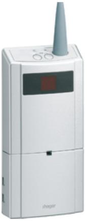
1 application software A faire Radio ON/OFF Input/Output products Electrical/Mechanical characteristics: see product user manual Product reference Product designation Application software ref TP device Radio device TRM690G Output 200W 2 lines + 2-fold embedded input KNX radio STRM690G TRM693G 1 output 3A 230V + 2-fold embedded input KNX radio STRM693G TRM694G 1 free outlet with 4A potential + 2- fold embedded input KNX radio STRM694G TRM690G - TRM693G - TRM694G 1 6LE001918B
2 Content 1. Presentation General About the program ETS ETS compatibility Application descriptions Plugin TR Easy tool software appearance General Description Installation of the device Overview presentation Description of the device Function modules of the application Output ON/OFF Input Programming by ETS Parameters Fixed parameters Functions of each switch actuator Timer Priority Automatic control Load shedding Scene Input operation mode Toggle switch ON/OFF Timer Shutter and blind Dimming Heating Priority Scene Alarm Automatic control deactivation Load shedding Windows contact Tariff Communication objects Output communication objects ON/OFF ON/OFF Status indication Timer Priority Scene ON/OFF automatic control Automatic control deactivation Load shedding Communication objects by input ON/OFF and toggle switch Timer Shutter and blind Dimming Heating Priority Scene Alarm Automatic control Load shedding Windows contact Tariff Configuration with media coupler Programming by Easy Tool Product overview Repeater Function Product functions at output ON/OFF Timer Priority Automatic control TRM690G - TRM693G - TRM694G 2 6LE001918B
3 4.3.5 Load shedding Scene Input operation mode Lighting Toggle switch Timer Priority ON/OFF Automatic control Load shedding Relative or absolute dimming (Brightness value) Dimming Dimming automatic control Shutter/blind Up/down Shutter or blind angle Priority Alarm Shutter/blind automatic control Heating/Cooling Setpoint selection Heating/Cooling Priority Heating automatic control Metering Automatic control deactivation Scene Factory reset Factory reset by ETS via the media coupler Factory reset on the product Characteristics TRM690G - TRM693G - TRM694G 3 6LE001918B
4 1. Presentation 1.1 General The purpose of this manual is to describe the operation and configuration of the KNX-devices using the ETS program. It consists of 4 parts: - General information. - The parameters and KNX objects available. - The Easy tool configurations are available. - Technical characteristics. 1.2 About the program ETS ETS compatibility The application programs are compatible with ETS4 and ETS5. They can be downloaded from our website under the order number. ETS Version ETS4 (V4.1.8 or higher) ETS5 File extension of compatible files *.knxprod *.knxprod Application descriptions Application STRM690G STRM693G STRM694G Product reference TRM690G TRM693G TRM694G Plugin TR131 The TR131 media coupler enables confuguration by ETS of RF devices for a KNX radio installation or a mixed KNX installation including RF devices and wired buses. The TR131 Plugin must be installed in the ETS software to configure the radio products Easy tool software appearance This product can also be configured using the TXA100 configuration tool. It is composed of a TJA665 configuration server. It is essential to update the configuration server software version. (Please refer to the TXA100 user manual). TRM690G - TRM693G - TRM694G 4 6LE001918B
5 2. General Description All radio transmitters referred to in this document are radio quicklink products. They can be recognised by the configuration cfg push button with which they are all equipped. Quicklink indicates the configuration without tools mode. These products can also be configured in E mode by the USB configurer or in S mode by ETS via the media coupler. Within the same installation, a single configuration mode may be used. To re-use a product which has already been programmed in another installation, whatever the configuration mode, a factory reset must be performed on the product. TRM690G - TRM693G - TRM694G 5 6LE001918B
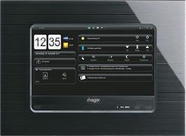

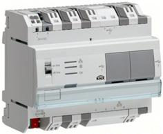


6 2.1 Installation of the device Overview presentation Load TRM690G Switch TRM693G Switch TRM694G Switch Radio switch Lighting-Shutter Control KNX Detector KNX Switch Radio detector KNX Local server ETHERNET Touchscreen Touchpad Smartphone TRM690G - TRM693G - TRM694G 6 6LE001918B
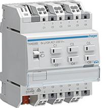
7 2.1.2 Description of the device - TRM690G - TRM693G - TRM694G TRM690G - TRM693G - TRM694G 7 6LE001918B
8 2.2 Function modules of the application Output ON/OFF Load shedding P R I O R I T Y High Low Priority level 1 Priority P R I O R I T Y High Low Priority level 2 OUTPUT MODULE Output ON/OFF Basic functions* P R I O R I T Y High Low Priority level 3 * ON/OFF - Timer - Scene: The last command received will have priority. The applications allow individual configuration of the device outputs. The most important functions are: ON/OFF An output can be switched on or off using the ON/OFF function. The command can come from switches, buttons or other control inputs. TRM690G - TRM693G - TRM694G 8 6LE001918B
9 Timer The Timer function is used to switch an output on for a programmable period. A programmable Cut-OFF pre-warning announces the end of the delay time by a 1-second inversion of the output status. The timer duration can be modified via the bus KNX. Priority The Priority function is used to force the output into a defined state. The Priority function is controlled with a 2-bit command. Priority: Load shedding > Priority > Basic function. Application: Keeping lighting on for security reasons. Automatic control The Automatic control function is used to command an output in parallel to the ON/OFF function. The two functions have the same level of priority. The last command received will act on the status of the output. An additional command object is used to activate or deactivate the Automatic control. Load shedding The Load shedding function is used to force an output to OFF. Load shedding is activated by receipt of a 1-byte command. Priority: Load shedding > Priority > Basic function. This command has the highest priority. No other command is taken into account if the mode is active. The status of the output is memorised but not applied. At the end of load shedding, the output is switched to the theoretical status without Load shedding (memorisation). Note: The Load shedding function is only available in products TRM693G and TRM694G. Scene The Scene function is used to switch groups of outputs into a configurable predefined state. Pressing a push button activates a scene. A scene is activated by receipt of a 1-byte command. Each output can be included in 64 different scenes. Status indication The Status indication sends the switching status of the individual output contact on the KNX bus. Communication objects ON/OFF Timer Scene Priority ON/OFF automatic control Automatic control deactivation 1 Output ON/OFF Automatic control deactivation status Status indication ON/OFF Status indication priority Load shedding TRM690G - TRM693G - TRM694G 9 6LE001918B
10 2.2.2 Input The command organs connected to inputs (remote switch, switch, automation) enable lighting, shutters, blinds, heating and scenes commands. The most important functions are: Toggle switch The Toggle switch function consists in inverting the output status after each press. ON/OFF The ON/OFF function a lighting, rolling shutter or heating circuit to be switched on or off. The command can come from switches, push-buttons or automations. Timer The Timer function enables a lighting, rolling shutter or heating circuit to be switched on or off for a programmable length of time. A short press on the push-button re-launches the timer. The timer can be interrupted before the end of the time by a long press. A programmable Cut-OFF pre-warning announces the end of the delay time by a 1-second inversion of the output status. Shutter/blind This function enables a rolling shutter or a blind to be controlled from 2 push-buttons. The Up/Down command (Up/Down object) is issued by a long press on the button. The Stop/Tilt function issues the object Tilt/Stop (short press). Dimming This function enables a light to be dimmed from one or two input contacts. The ON/OFF function issues the object ON/OFF (short press). The Dimming function issues the object Dimming (long press). Heating This function enables a heating or air-conditioning instruction (Auto, Comfort, Economy, Night setpoint, Frost protection) to be selected. It enables instruction exceptions to be issued in order to increase or reduce the temperature. The command can come from switches, push-buttons or automations. Priority The Priority function enables an input to be forced into a defined state. The priority action depends on the type of application commanded: Lighting ON/OFF, Rolling shutter, Heating. Scene This function enables scenes to be saved or selected. These concern different types of output (lighting, blind, shutter, heating) to create ambiances or scenarios (leaving scenario, reading ambiance etc.). Alarms The wind, rain and freeze Alarm functions enable alarms to be issued on a cyclical basis to the bus from automations (anemometer, rain detector, twilight switch, etc.). Automatic control The Automatic control function enables an output to be controlled in parallel to the standard control. An additional command object (Automatic control deactivation) is used to activate or deactivate Automatic control. Load shedding The Load shedding function is used to force an output to OFF. Load shedding is activated by receipt of a 1-byte command. At the end of load shedding, the output is switched to the theoretical status without Load shedding (memorisation). Windows contact The Window contact function enables the window opening/closing information to be sent to the KNX bus. TRM690G - TRM693G - TRM694G 10 6LE001918B
11 Tariff The Tariff function enables T1/T2 tariff information to be sent to the KNX bus. Communication objects ON/OFF Timer Dimming Brightness value Up/down Step/stop (short press) Stop (short press) Position in % Slat angle in % Heating/Cooling - changeover Status indication ON/OFF 1 input Override setpoint Setpoint selection Scene Priority Alarm 1 Alarm 2 Alarm 3 Automatic control deactivation Load shedding Windows contact status Tariff TRM690G - TRM693G - TRM694G 11 6LE001918B
12 3. Programming by ETS The function of the different devices only differs in the number of outputs. For this reason, only one device or one output will ever be described. 3.1 Parameters Fixed parameters The fixed parameters define the operating mode of the output relays. Parameter Description Value Output contact Parameters overwrite at next download (scenes) Status after priority On receipt of an ON command: The output relay closes. The parameter values stored in the device will be overwritten with the ETS configured values at the next download. At the end of the priority, the output is: Switched back to the status before priority was activated. Status after ETS download The output status remains unchanged after ETS download. Note: During ETS-parameters download, the outputs remain unchanged. Status at supply return The output status remains unchanged when the power is turned back on. Note: The priority functions that were present before the bus power cut are no longer active (Load shedding, Priority). Normally open Active Status before priority Maintain status Maintain status Functions of each switch actuator Timer The Timer function is used to switch on a lighting circuit for a programmable period. The timer may be interrupted before expiry of the delay time. A programmable Cut-OFF pre-warning announces the end of the delay time by a 1-second inversion of the output status. Parameter Description Value Timer duration This parameter determines the timer duration. Not active, 1 s, 2 s, 3 s, 5 s, 10 s, 15 s, 20 s, 30 s, 45 s, 1 min, 1 min 15 s, 1 min 30 s, 2 min, 2 min 30 s, 3 min*, 5 min, 15 min, 20 min, 30 min, 1 h, 2 h, 3 h, 5 h, 12 h, 24 h * Default value TRM690G - TRM693G - TRM694G 12 6LE001918B
13 Parameter Description Value Cut-OFF pre-warning This parameter determines the lead time of the cut-off pre-warning. Not active, 15 s, 30 s*, 1 min Operating principle: Control Start Start End Start Start End Output 1 0 Tm Tm Tm Tp Tp Status indication ON/ OFF ON OFF ON OFF ON OFF Tm: Timer duration Tp: Pre-warning lead time Note: If the lead time of the cut-off pre-warning is greater than the duration of the timer, the cut-off pre-warning is not triggered. Communication objects: 2 - Output - Timer (1 Bit DPT_Switch) 10 - Output - Timer (1 Bit DPT_Switch) * Default value TRM690G - TRM693G - TRM694G 13 6LE001918B
14 Priority The Priority function is used to force the output into a defined state. Priority: Load shedding > Priority > Basic function. Only a Priority OFF command authorizes the output for control. At the end of the priority, the output returns to the status it had before the priority (Memorisation function). The device responds to telegrams received via the Priority object, as given in the following table: Telegram received by the priority operation object Hexadecimal Value Bit 1 (MSB) Binary Value Bit 0 (LSB) Output behaviour End of the priority End of the priority Priority OFF Priority ON Operating principle: Priority ON Priority ON End of the priority End of the priority Priority command End of the priority Priority OFF Priority OFF Output 1 0 Status indication ON/OFF ON OFF ON OFF Status indication priority Active Not active Communication objects: Communication objects: 3 - Output - Priority (2 Bit DPT_Bool_Control) 4 - Output - Status indication priority (1 Bit DPT_State) 12 - Output - Priority (2 Bit DPT_Bool_Control) 13 - Output - Status indication priority (1 Bit DPT_State) TRM690G - TRM693G - TRM694G 14 6LE001918B
15 Automatic control The Automatic control function is used to command an output in parallel to the ON/OFF function. The two functions have the same level of priority. The last command received will act on the status of the output. An additional command object is used to activate or deactivate the Automatic control. Example: when an output is controlled by a button and in parallel by an automatic control (timer, twilight switch, weather station, etc.) the automatic control can be deactivated for reasons of comfort (vacations, public holidays, etc.). Operating principle: ON/OFF ON/OFF automatic control Automatic control deactivation Not active Active Not active Automatic control deactivation status Not active Active Not active Output 1 0 Communication objects: 6 - Output - ON/OFF automatic control (1 Bit DPT_Switch) 7 - Output - Automatic control deactivation (1 Bit DPT_Enable) 8 - Output - Automatic control deactivation status (1 Bit DPT_Enable) 4 - Output - ON/OFF automatic control (1 Bit DPT_Switch) 6 - Output - Automatic control deactivation (1 Bit DPT_Enable) 7 - Output - Automatic control deactivation status (1 Bit DPT_Enable) TRM690G - TRM693G - TRM694G 15 6LE001918B
16 Load shedding The Load shedding function is used to force an output to OFF. Load shedding is activated by receipt of a 1-byte command. Priority: Load shedding > Priority > Basic function. This command has the highest priority. No other command is taken into account if the mode is active. The status of the output is memorised but not applied. At the end of load shedding, the output is switched to the theoretical status without Load shedding (memorisation). Note: The Load shedding function is only available in products TRM693G and TRM694G. Example: Load shedding function ON/OFF Load shedding Output 1 0 Status indication ON/ OFF ON OFF ON OFF Communication objects: 9 - Output - Load shedding (1 Bit DPT_Switch) TRM690G - TRM693G - TRM694G 16 6LE001918B
17 Scene Parameter Description Value Number of scenes used This parameter determines the number of scenes used. 8* Note: If the Scene number received on the Scene object is greater than the maximum number of scenes, the status of the output remains unchanged. Scene x Parameter Description This parameter is used to activate the scene in question. Parameter Description Value Output status for scene x x = 1 to 64 On activation of Scene x, the output is: Selectively switched on. Selectively switched off. ON* OFF Note: Each output has up to 64 scenes available, in accordance with the Number of scenes used parameter. Communication objects: 5 - Output - Scene (1 Byte DPT_SceneControl) 11 - Output - Scene (1 Byte DPT_SceneControl) * Default value TRM690G - TRM693G - TRM694G 17 6LE001918B
18 Operating principle: ON/OFF ON ON OFF Status indication ON/OFF ON OFF ON OFF ON Scene Scene 1 memorisation Scene 1 execution Scene 1 memorisation Scene 1 execution Output 1 0 Learning and storing scenes This process is used to change and store a scene. For example, by locally pressing the key in the room or by emission of the values from a visualization. To access and store scenes, the following values must be sent: Scene number Access scene (Object value: 1 byte) Store scene (Object value: 1 byte) 1-64 = Scene number -1 = Scene number +128 Examples Here is the scene memorisation for local switches, for example. Activate scene by briefly pressing the transmitter that starts it. The outputs (lights, shutters, etc.) are set in the desired state using the usual local control devices (buttons, remote control, etc.). Memorise the status of the outputs with a press greater than 5 seconds long on the transmitter that starts the scene. The memorisation can be displayed by short-term activation of the outputs. TRM690G - TRM693G - TRM694G 18 6LE001918B
19 3.1.3 Input operation mode This configuration enables the input operating mode to be defined. These parameters are available for each input individually. The input default value is not active. The following parameters are available: - Toggle switch - ON/OFF - Timer - Shutter/blind - Dimming - Heating - Priority - Scene - Alarm - Automatic control deactivation - Load shedding - Windows contact - Tariff TRM690G - TRM693G - TRM694G 19 6LE001918B
20 Toggle switch This function enables a lighting circuit or any other load to be commanded to switch on or off. Each time the push-button is pressed the output status is inverted. Description: After a press on the push-button, according to the object Indication of ON/OFF status an ON or OFF command will be issued to the bus via the object ON/OFF.. Operating principle: Input 1 1 Input t 0 t ON/OFF ON OFF ON OFF ON OFF ON OFF Status indication ON/OFF 1 Output 0 ON OFF ON OFF ON OFF ON OFF t t t Communication objects: Communication objects: 10 - Input 1 - Status indication ON/OFF (1 Bit DPT_Switch) 11 - Input 1 - ON/OFF (1 Bit DPT_Switch) 20 - Input 2 - Status indication ON/OFF (1 Bit DPT_Switch) 21 - Input 2 - ON/OFF (1 Bit DPT_Switch) 14 - Input 1 - Status indication ON/OFF (1 Bit DPT_Switch) 15 - Input 1 - ON/OFF (1 Bit DPT_Switch) 24 - Input 2 - Status indication ON/OFF (1 Bit DPT_Switch) 25 - Input 2 - ON/OFF (1 Bit DPT_Switch) TRM690G - TRM693G - TRM694G 20 6LE001918B
21 ON/OFF An output can be switched on or off using the ON/OFF function. The command can come from switches, push-buttons or automations. Parameter Description Value Using mode This parameter defines the commands issued at changes of the input status. ON/-, OFF/-, ON/OFF*, OFF/ON, -/ON, -/OFF Note: By default, the input operates like an NO contact (Normally open). If the parameter Inverted is validated, the input operates like an NC contact (Normally closed). The operation of the input contact may be configured according to whether the contact is open or closed (ON, OFF). 6 different combinations are available: Function by press Function on release ON - OFF - ON OFF OFF ON - ON - OFF Communication objects: Communication objects: 11 - Input 1 - ON/OFF (1 Bit DPT_Switch) 21 - Input 2 - ON/OFF (1 Bit DPT_Switch) 15 - Input 1 - ON/OFF (1 Bit DPT_Switch) 25 - Input 2 - ON/OFF (1 Bit DPT_Switch) * Default value TRM690G - TRM693G - TRM694G 21 6LE001918B
22 Timer The Timer function enables a lighting, rolling shutter or heating circuit to be switched on or off for a programmable length of time. A short press on the push-button re-launches the timer. The timer can be interrupted before the end of the time by a long press. Operating principle: Input 1 Short press Long key-press 0 t Timer Start End t Communication objects: Communication objects: 11 - Input 1 - Timer (1 Bit DPT_Switch) 21 - Input 2 - Timer (1 Bit DPT_Switch) 15 - Input 1 - Timer (1 Bit DPT_Switch) 25 - Input 2 - Timer (1 Bit DPT_Switch) TRM690G - TRM693G - TRM694G 22 6LE001918B
23 Shutter and blind This function enables a rolling shutter or a blind to be controlled from 2 push-buttons. The Up/Down command (Up/Down object) is issued by a long press on the button. The Stop/Tilt function issues the object Tilt/Stop (short press). Parameter Description Value Closing type Shutter This parameter defines the operating mode used for the affected outputs. An operating mode of the shutter and blind type gives access to additional parameters to control the slat pitch. Shutter* Shutter and blind Parameter Description Value Shutter function 2-button shutter The shutter command works: Using the input contact programmed to up or down Using the input contact programmed to up or down. According to whether the input contact is open or closed. According to a position value in % on pressing and releasing the input contact. 1-button shutter 2-button shutter* Switch for shutter control Position (0-100%) Parameter Description Value Function by press On shutting the input contact, the order issued is: Opening the rolling shutter. Closing the rolling shutter. Up* Down Note: This parameter is only visible when the parameter Shutter function has the value: 2-button shutter. Switch for shutter control Parameter Description Value Using mode This parameter defines the commands issued at changes of the input status. Up/- Down/- Up/down* Down/Up -/Up -/Down Up/stop Stop/up Note: This parameter is only visible when the parameter Shutter function has the value: Switch for shutter control. The operation of the input contact may be configured according to whether the contact is open or closed (Up, Down). * Default value TRM690G - TRM693G - TRM694G 23 6LE001918B
24 6 different combinations are available: Function by press Function on release Up - Down - Up Down Down Up - Up - Down Up Stop Stop Up Note: By default, the input operates like an NO contact (Normally open). If the parameter Inverted is validated, the input operates like an NC contact (Normally closed). Communication objects: Communication objects: 11 - Input 1 - Up/down (1 Bit DPT_UpDown) 12 - Input 1 - Stop (short press) (1 Bit DPT_Trigger) 21 - Input 2 - Up/down (1 Bit DPT_UpDown) 22 - Input 2 - Stop (short press) (1 Bit DPT_Trigger) 15 - Input 1 - Up/down (1 Bit DPT_UpDown) 16 - Input 1 - Stop (short press) (1 Bit DPT_Trigger) 25 - Input 2 - Up/down (1 Bit DPT_UpDown) 26 - Input 2 - Stop (short press) (1 Bit DPT_Trigger) Position (0-100%) This function enables the object Position in % to be issued according to 2 types of event. These 2 events correspond to the open or closed status of the input contact. Additional parameters define the positions for the 2 events. Parameter Description Value Using mode The shutter command operates according to a position value in %: On pressing and releasing the input contact. On only pressing the input contact. On only releasing the input contact. Function by press/ release* Function by press Function on release Note: This parameter is only visible when the parameter Shutter function has the value: Position (0-100%). Parameter Description Value Position by press (0-100%) This parameter defines the position of the rolling shutter to apply during the press * Note: This parameter is only visible when the parameter Shutter function has the value: Position (0-100%). * Default value TRM690G - TRM693G - TRM694G 24 6LE001918B
25 Parameter Description Value Position on release (0-100%) This parameter defines the position of the rolling shutter to apply at release. 0* Note: This parameter is only visible when the parameter Shutter function has the value: Position (0-100%). Note: By default, the input operates like an NO contact (Normally open). If the parameter Inverted is validated, the input operates like an NC contact (Normally closed). Communication objects: Communication objects: 15 - Input 1 - Position in % (1 Byte DPT_Scaling) 25 - Input 2 - Position in % (1 Byte DPT_Scaling) 19 - Input 1 - Position in % (1 Byte DPT_Scaling) 29 - Input 2 - Position in % (1 Byte DPT_Scaling) Shutter and blind Parameter Description Value Blind function The shutter/blind command operates: Using the input contact programmed to up or down. According to the slat angle value in % on pressing and releasing the input contact. According to a position value in % and a slat angle in % on pressing and releasing the input contact. Up/down/step/stop* Slat angle (0-100%) Position/Slat angle (0-100%) Up/down/step/stop Parameter Description Value Function by press On shutting the input contact, the order issued is: Shutter or blind open. Shutter or blind closed. Up* Down Note: This parameter is only visible when the parameter Blind function has the value: Up/down/step/stop. Communication objects: Communication objects: 11 - Input 1 - Up/down (1 Bit DPT_UpDown) 12 - Input 1 - Step/stop (short press) (1 Bit DPT_Step) 21 - Input 2 - Up/down (1 Bit DPT_UpDown) 22 - Input 2 - Step/stop (short press) (1 Bit DPT_Step) 15 - Input 1 - Up/down (1 Bit DPT_UpDown) 16 - Input 1 - Step/stop (short press) (1 Bit DPT_Step) 25 - Input 2 - Up/down (1 Bit DPT_UpDown) 26 - Input 2 - Step/stop (short press) (1 Bit DPT_Step) * Default value TRM690G - TRM693G - TRM694G 25 6LE001918B
26 Position/Slat angle (0-100%) This function enables the objects Position in % and Slat angle in % to be issued according to 2 types of event. These 2 events correspond to the open or closed status of the input contact. Additional parameters define the positions for the 2 events. Parameter Description Value Using mode The shutter/blind command operates according to a position value in % and a slat angle in %: On pressing and releasing the input contact. On only pressing the input contact. On only releasing the input contact. Function by press/ release* Function by press Function on release Note: This parameter is only visible when the parameter Blind function has the value: Slat angle (0-100%) or Position/Slat angle (0-100%). Parameter Description Value Slat angle by press (0-100%) This parameter defines the slat position to apply during the press * Note: This parameter is only visible when the parameter Blind function has the value: Slat angle (0-100%) or Position/Slat angle (0-100%). Parameter Description Value Slat angle on release (0-100%) This parameter defines the slat position to apply at release. 0* Note: This parameter is only visible when the parameter Blind function has the value: Slat angle (0-100%) or Position/Slat angle (0-100%). Note: By default, the input operates like an NO contact (Normally open). If the parameter Inverted is validated, the input operates like an NC contact (Normally closed). Parameter Description Value Position by press (0-100%) This parameter defines the blind position to apply during the press * Note: This parameter is only visible when the parameter Blind function has the value: Position/Slat angle (0-100%). Parameter Description Value Position on release (0-100%) This parameter defines the blind position to apply at release. 0* Note: This parameter is only visible when the parameter Blind function has the value: Position/Slat angle (0-100%). Note: By default, the input operates like an NO contact (Normally open). If the parameter Inverted is validated, the input operates like an NC contact (Normally closed). * Default value TRM690G - TRM693G - TRM694G 26 6LE001918B
27 Communication objects: Communication objects: 15 - Input 1 - Position in % (1 Byte DPT_Scaling) 16 - Input 1 - Slat angle in % (1 Byte DPT_Scaling) 25 - Input 2 - Position in % (1 Byte DPT_Scaling) 26 - Input 2 - Slat angle in % (1 Byte DPT_Scaling) 19 - Input 1 - Position in % (1 Byte DPT_Scaling) 20 - Input 1 - Slat angle in % (1 Byte DPT_Scaling) 29 - Input 2 - Position in % (1 Byte DPT_Scaling) 30 - Input 2 - Slat angle in % (1 Byte DPT_Scaling) Input 1 0 t Position in % 63% 25% t Slat angle in % 17% 49% Note: The value of the object Position in % is issued before the object value Slat angle in % so that the output module can position the blind before tilting it. t TRM690G - TRM693G - TRM694G 27 6LE001918B
28 Dimming Parameter Description Value Dimming function The dimming command operates: Using the input contact configured to increase or decrease (Dimming command on 2 buttons). Using the input contact configured to increase or decrease (Dimming command on 1 button). According to a brightness value in % on pressing and releasing the input contact. Increase/decrease* Increase/decrease Toggle switch Brightness value Increase/decrease Toggle switch This function enables the objects ON/OFF, Dimming and ON/OFF status indication to be issued according to 2 types of event. These 2 events correspond to a short press enabling the ON/OFF command or long press enabling the dimming command. This function corresponds to the dimming command on 1 button. Input 1 Apl Apl Apl Apl Apl t ON/OFF ON OFF ON Dimming Decrease Increase t Stop Stop t Status indication ON/OFF ON OFF ON Output 100% t Apl: Long key-press 0% t * Default value TRM690G - TRM693G - TRM694G 28 6LE001918B
29 Communication objects: Communication objects: 10 - Input 1 - Status indication ON/OFF (1 Bit DPT_Switch) 11 - Input 1 - ON/OFF (1 Bit DPT_Switch) 14 - Input 1 - Dimming (4 Bits DPT_Control_Dimming) 20 - Input 2 - Status indication ON/OFF (1 Bit DPT_Switch) 21 - Input 2 - ON/OFF (1 Bit DPT_Switch) 24 - Input 2 - Dimming (4 Bits DPT_Control_Dimming) 14 - Input 1 - Status indication ON/OFF (1 Bit DPT_Switch) 15 - Input 1 - ON/OFF (1 Bit DPT_Switch) 18 - Input 1 - Dimming (4 Bits DPT_Control_Dimming) 24 - Input 2 - Status indication ON/OFF (1 Bit DPT_Switch) 25 - Input 2 - ON/OFF (1 Bit DPT_Switch) 28 - Input 2 - Dimming (4 Bits DPT_Control_Dimming) Increase/decrease This function enables the objects ON/OFF and Dimming to be issued according to 2 types of events. These 2 events correspond to a short press enabling the ON/OFF command or long press enabling the dimming command. Additional parameters defined the dimming direction. This function corresponds to the dimming command on 2 buttons. Parameter Description Value Function by press This parameter defines the dimming direction corresponding to the input. Increase* Decrease Note: This parameter is only visible when the parameter Dimming function has the value: Increase/decrease. Communication objects: Communication objects: 11 - Input 1 - ON/OFF (1 Bit DPT_Switch) 14 - Input 1 - Dimming (4 Bits DPT_Control_Dimming) 21 - Input 2 - ON/OFF (1 Bit DPT_Switch) 24 - Input 2 - Dimming (4 Bits DPT_Control_Dimming) 15 - Input 1 - ON/OFF (1 Bit DPT_Switch) 18 - Input 1 - Dimming (4 Bits DPT_Control_Dimming) 25 - Input 2 - ON/OFF (1 Bit DPT_Switch) 28 - Input 2 - Dimming (4 Bits DPT_Control_Dimming) * Default value TRM690G - TRM693G - TRM694G 29 6LE001918B
30 Example: Input 1: Increase Input 2: Decrease 1 Apl Apl Input 1 0 Apl Apl t Input t ON/OFF ON OFF t Increase Decrease Dimming Stop Stop t 100% Output 66% 33% 0% t Apl: Long key-press Brightness value Parameter Description Value Using mode The dimming command operates according to a brightness value in %: On pressing and releasing the input contact. On only pressing the input contact. On only releasing the input contact. Function by press/ release* Function by press Function on release Note: This parameter is only visible when the parameter Dimming function has the value: Brightness value. Parameter Description Value Brightness value by press This parameter defines the brightness value to apply during the press * Note: This parameter is only visible when the parameter Dimming function has the value: Brightness value. * Default value TRM690G - TRM693G - TRM694G 30 6LE001918B
31 Parameter Description Value Brightness value at release This parameter defines the brightness value to apply at release. 0* Note: This parameter is only visible when the parameter Dimming function has the value: Brightness value. Note: By default, the input operates like an NO contact (Normally open). If the parameter Inverted is validated, the input operates like an NC contact (Normally closed). Communication objects: Communication objects: 15 - Input 1 - Brightness value (1 Byte DPT_Scaling) 25 - Input 2 - Brightness value (1 Byte DPT_Scaling) 19 - Input 1 - Brightness value (1 Byte DPT_Scaling) 29 - Input 2 - Brightness value (1 Byte DPT_Scaling) Input 1 0 t Brightness value 30% 80% t * Default value TRM690G - TRM693G - TRM694G 31 6LE001918B
32 Heating Parameter Description Value Heating function The heating command operates: According to a heating instruction on pressing and releasing the input contact. Using the input contact configured in heating or cooling mode. Setpoint selection* Heating/Cooling Heating/Cooling This function enables the object (Heating/cooling-changeover) to be issued on the KNX bus. Communication objects: 11 - Input 1 - Heating/Cooling - changeover (1 Bit DPT_Cooling/heating) 21 - Input 2 - Heating/Cooling - changeover (1 Bit DPT_Cooling/heating) 15 - Input 1 - Heating/Cooling - changeover (1 Bit DPT_Cooling/heating) 25 - Input 2 - Heating/Cooling - changeover (1 Bit DPT_Cooling/heating) Note: By default, the input operates like an NO contact (Normally open). If the parameter Inverted is validated, the input operates like an NC contact (Normally closed). Input 1 0 t Heating/Cooling - changeover 1 Heating 0 Cooling t Setpoint selection This function enables the object Instruction selection to be issued according to 2 types of event. These 2 events correspond to the open or closed status of the input contact. Extra parameters define the heating instructions for 2 events. * Default value TRM690G - TRM693G - TRM694G 32 6LE001918B
33 Parameter Description Value Using mode The heating command operates according to a heating instruction: On pressing and releasing the input contact. On only pressing the input contact. On only releasing the input contact. Function by press/release* Function by press Function on release Note: This parameter is only visible when the parameter Heating function has the value: Setpoint selection. Parameter Description Value Setpoint by press This parameter defines the heating instruction to apply during the press. Auto Comfort* Standby Night setpoint Frost protection Parameter Description Value Threshold at release This parameter defines the heating instruction to apply at release. Auto Comfort Standby Night setpoint* Frost protection Note: By default, the input operates like an NO contact (Normally open). If the parameter Inverted is validated, the input operates like an NC contact (Normally closed). Communication objects: 15 - Input 1 - Setpoint selection (1 Byte DPT_HVAC mode) 25 - Input 2 - Setpoint selection (1 Byte DPT_HVAC mode) 19 - Input 1 - Setpoint selection (1 Byte DPT_HVAC mode) 29 - Input 2 - Setpoint selection (1 Byte DPT_HVAC mode) * Default value TRM690G - TRM693G - TRM694G 33 6LE001918B
34 Priority The Priority function is used to force the output into a defined state. The priority action depends on the type of application commanded: Lighting ON/OFF, Rolling shutter, Heating. This function the priority or priority cancellation controls to be issued. No other command is taken into account when the Priority is active. Only priority or alarm cancellation commands will be taken into account. Parameter Description Value Using mode This parameter defines the priority type to apply during the press. Priority ON/down/comfort* Priority OFF/up/frost protection Note: By default, the input operates like an NO contact (Normally open). If the parameter Inverted is validated, the input operates like an NC contact (Normally closed). Communication objects: Communication objects: 13 - Input 1 - Priority (2 Bit DPT_Bool_Control) 23 - Input 2 - Priority (2 Bit DPT_Bool_Control) 17 - Input 1 - Priority (2 Bit DPT_Bool_Control) 27 - Input 2 - Priority (2 Bit DPT_Bool_Control) * Default value TRM690G - TRM693G - TRM694G 34 6LE001918B
35 Scene This function enables scenes to be saved or selected. These concern different types of output (lighting, blind, shutter, heating) to create ambiances or scenarios (leaving scenario, reading ambiance etc.). Parameter Description Value Scene function The scene command operates: According to a scene number on pressing the input contact. Scene 1-64* According to a scene number on pressing and releasing the input contact. Switch for scene Scene 1-64 Parameter Description Value Scene number (1-64) by press This parameter defines the scene number to apply during the press. 1*...64 Note: This parameter is only visible when the parameter Scene function has the value: Scene Communication objects: Communication objects: 15 - Input 1 - Scene (1 Byte DPT_SceneControl) 25 - Input 2 - Scene (1 Byte DPT_SceneControl) 19 - Input 1 - Scene (1 Byte DPT_SceneControl) 29 - Input 2 - Scene (1 Byte DPT_SceneControl) Switch for scene Parameter Description Value Using mode The scene number is sent On pressing and releasing the input contact. On only pressing the input contact. On only releasing the input contact. Function by press/ release* Function by press Function on release Note: This parameter is only visible when the parameter Scene function has the value: Switch for scene. Parameter Description Value Scene number (1-64) by press This parameter defines the scene number to apply during the press. 1*...64 * Default value TRM690G - TRM693G - TRM694G 35 6LE001918B
36 Parameter Description Value Scene number (1-64) on release This parameter defines the scene number to apply at release *...64 Note: By default, the input operates like an NO contact (Normally open). If the parameter Inverted is validated, the input operates like an NC contact (Normally closed). Communication objects: Communication objects: 15 - Input 1 - Scene (1 Byte DPT_SceneControl) 25 - Input 2 - Scene (1 Byte DPT_SceneControl) 19 - Input 1 - Scene (1 Byte DPT_SceneControl) 29 - Input 2 - Scene (1 Byte DPT_SceneControl) * Default value TRM690G - TRM693G - TRM694G 36 6LE001918B
37 Alarm The Alarm function issues alarms on a cyclical basis to the bus from automations (anemometer, rain detector, twilight switch etc.). The cycle time is set to 10 minutes. Parameter Description Value Alarm type This parameter defines the type of alarm to be issued on the KNX bus. Alarm 1* Alarm 2 Alarm 3 Communication objects: Communication objects: 11 - Input 1 - Alarm 1 (1 Bit DPT_Alarm) 21 - Input 2 - Alarm 1 (1 Bit DPT_Alarm) 11 - Input 1 - Alarm 2 (1 Bit DPT_Alarm) 21 - Input 2 - Alarm 2 (1 Bit DPT_Alarm) 11 - Input 1 - Alarm 3 (1 Bit DPT_Alarm) 21 - Input 2 - Alarm 3 (1 Bit DPT_Alarm) 15 - Input 1 - Alarm 1 (1 Bit DPT_Alarm) 25 - Input 2 - Alarm 1 (1 Bit DPT_Alarm) 15 - Input 1 - Alarm 2 (1 Bit DPT_Alarm) 25 - Input 2 - Alarm 2 (1 Bit DPT_Alarm) 15 - Input 1 - Alarm 3 (1 Bit DPT_Alarm) 25 - Input 2 - Alarm 3 (1 Bit DPT_Alarm) Input t Alarm t Cycle time Cycle time * Default value TRM690G - TRM693G - TRM694G 37 6LE001918B
38 Automatic control deactivation The Automatic control function enables an output to be controlled in parallel to the standard control. An additional command object (Automatic control deactivation) is used to activate or deactivate Automatic control. Note: By default, the input operates like an NO contact (Normally open). If the parameter Inverted is validated, the input operates like an NC contact (Normally closed). Communication objects: Communication objects: 11 - Input 1 - Automatic control deactivation (1 Bit DPT_Enable) 21 - Input 2 - Automatic control deactivation (1 Bit DPT_Enable) 15 - Input 1 - Automatic control deactivation (1 Bit DPT_Enable) 25 - Input 2 - Automatic control deactivation (1 Bit DPT_Enable) Load shedding The Load shedding function is used to force an output to OFF. Load shedding is activated by receipt of a 1-byte command. At the end of load shedding, the output is switched to the theoretical status without Load shedding (memorisation). Note: By default, the input operates like an NO contact (Normally open). If the parameter Inverted is validated, the input operates like an NC contact (Normally closed). Communication objects: 11 - Input 1 - Load shedding (1 Bit DPT_Bool) 21 - Input 2 - Load shedding (1 Bit DPT_Bool) Communication objects: 15 - Input 1 - Load shedding (1 Bit DPT_Bool) 25 - Input 2 - Load shedding (1 Bit DPT_Bool) Windows contact The Window contact function enables the window opening/closing information to be sent to the KNX bus. Input 1 0 t Windows contact 0 Window open 1 Window closed t Note: By default, the input operates like an NO contact (Normally open). If the parameter Inverted is validated, the input operates like an NC contact (Normally closed). Communication objects: Communication objects: 11 - Input 1 - Windows contact (1 Bit DPT_Bool) 21 - Input 2 - Windows contact (1 Bit DPT_Bool) 15 - Input 1 - Windows contact (1 Bit DPT_Bool) 25 - Input 2 - Windows contact (1 Bit DPT_Bool) TRM690G - TRM693G - TRM694G 38 6LE001918B
39 Tariff The Tariff function enables Full Hour (FH) or Part Hour (PH) information to be sent to the KNX bus. Input 1 0 t Tariff 0 FH tariff 1 PH tariff t Note: By default, the input operates like an NO contact (Normally open). If the parameter Inverted is validated, the input operates like an NC contact (Normally closed). Communication objects: Communication objects: 15 - Input 1 - Tariff (1 Byte DPT_Tariff) 25 - Input 2 - Tariff (1 Byte DPT_Tariff) 19 - Input 1 - Tariff (1 Byte DPT_Tariff) 29 - Input 2 - Tariff (1 Byte DPT_Tariff) TRM690G - TRM693G - TRM694G 39 6LE001918B
40 3.2 Communication objects Output communication objects ON/OFF - TRM690G Number Name Function of the object Length C R W T 0 Output ON/OFF 1 bit C R W - 4 Output ON/OFF automatic control 1 bit C R W - 6 Output Automatic control deactivation 1 bit C R W - 7 Output Automatic control deactivation status 1 bit C R - T 8 Output Status indication ON/OFF 1 bit C R - T 10 Output Timer 1 bit C R W - 11 Output Scene 1 byte C R W - 12 Output Priority 2 bit C R W - 13 Output Status indication priority 1 bit C R - T - TRM693G - TRM694G Number Name Function of the object Length C R W T 0 Output ON/OFF 1 bit C R W - 1 Output Status indication ON/OFF 1 bit C R - T 2 Output Timer 1 bit C R W - 3 Output Priority 2 bit C R W - 4 Output Status indication priority 1 bit C R - T 5 Output Scene 1 byte C R W - 6 Output ON/OFF automatic control 1 bit C R W - 7 Output Automatic control deactivation 1 bit C R W - 8 Output Automatic control deactivation status 1 bit C R - T 9 Output Load shedding 1 bit C R W ON/OFF No. Name Function of the object Data type Flags 0 Output ON/OFF 1 bit DPT_Switch C, R, W These objects are always activated. They enable switching of the output contact in accordance with the value that is sent via the KNX bus. Normally open: - On input of an OFF command, the output relay contact opens. - On input of an ON command, the output relay contact closes. TRM690G - TRM693G - TRM694G 40 6LE001918B
41 Status indication No. Name Function of the object Data type Flags 1, 8 Output Status indication ON/OFF 1 bit DPT_Switch C, R, T These objects are always activated. This object allows the status of the output contact to be sent from the device over the KNX bus. Object value: - If the output relay is open, a telegram with logic value 0 is sent on the KNX bus. - If the output relay is closed, a telegram with logic value 1 is sent on the KNX bus. This object is sent when there is a status change Timer No. Name Function of the object Data type Flags 2, 10 Output Timer 1 bit DPT_Start C, R, W This object is activated when the Timer parameter is active. This object is used to activate the Timer function of the device via the KNX bus. Object value: - If a rising edge (0 to 1) arrives at this object, the output switches for a configurable period. - If a falling edge (1 to 0) arrives at this object, the output remains in its current state. Note: The timer duration can be interrupted by a long press on the button controlling the timer. Note: When a start command is received during the timer, the timer duration is reset. For further information, see: Timer Priority No. Name Function of the object Data type Flags 3, 12 Output Priority 2 bit DPT_Bool_Control C, R, W This object is activated if the Priority parameter is active. The status of the output contact is determined directly by this object. Details on the format of the object are given below. Telegram received by the priority operation object Hexadecimal Value Bit 1 (MSB) Binary Value Bit 0 (LSB) Output behaviour End of the priority End of the priority Priority OFF Priority ON The first bit of this object (Bit 0) determines the status of the output contact, which should be priority controlled. The second bit activates or deactivates the Priority. For further information, see: Priority. TRM690G - TRM693G - TRM694G 41 6LE001918B
42 No. Name Function of the object Data type Flags 4, 13 Output Status indication priority 1 bit DPT_State C, R, T This object is activated if the Priority parameter is active. This object allows the status of the Priority to be sent from the device on the KNX bus. Object value: 0 = Not forced, 1 = Forced: - If Priority is deactivated, a telegram is sent with logic value 0. - If Priority is activated, a telegram is sent with logic value 1. This object is sent when there is a status change. For further information, see: Priority Scene No. Name Function of the object Data type Flags 5, 11 Output Scene 1 byte DPT_SceneNumber This object is activated when the Scene parameter is active. This object is used to recall or save a scene. C, R, W Details on the format of the object are given below Learning Not used Scene number Bit 7: 0: The scene is called / 1: The scene is saved. Bit 6: Not used. Bit 5 to Bit 0: Scene numbers from 0 (Scene 1) to 63 (Scene 64). For further information, see: Scene ON/OFF automatic control No. Name Function of the object Data type Flags 6, 4 Output ON/OFF automatic control 1 bit DPT_Switch C, R, W This object is activated when the Automatic control parameter is active. They enable switching of the output contact in accordance with the value that is sent via the KNX bus. Normally open: - On input of an OFF command, the output relay contact opens. - On input of an ON command, the output relay contact closes. For further information, see: Automatic control. TRM690G - TRM693G - TRM694G 42 6LE001918B
43 Automatic control deactivation No. Name Function of the object Data type Flags 7, 6 Output Automatic control deactivation 1 bit DPT_Enable C, R, W This object is activated when the Automatic control deactivation parameter is active. This object is used to activate the automatic control function. Object value: - If the object receives the value 0, the automatic control function is inactive. - If the object receives the value 1, the automatic control function is active. For further information, see: Automatic control. No. Name Function of the object Data type Flags 8, 7 Output Automatic control deactivation status 1 bit DPT_Enable C, R, T This object is activated when the Automatic control deactivation parameter is active. This object is used to send the status of the Automatic control deactivation function of the device on the KNX bus. Object value: - If the Automatic control deactivation function is deactivated, a telegram with a logical value 0 is sent. - If the Automatic control deactivation function is activated, a telegram with a logical value 1 is sent. This object is sent when there is a status change. For further information, see: Automatic control Load shedding No. Name Function of the object Data type Flags 9 Output Load shedding 1 bit DPT_Bool C, R, W This object is activated when the Load shedding parameter is active. This object is used to force an output to OFF. Object value: - If the object receives the value 0, the output remains unchanged. - If the object receives the value 1, the output is forced to OFF. Note: The Load shedding function is only available in products TRM693G and TRM694G. For further information, see: Load shedding. TRM690G - TRM693G - TRM694G 43 6LE001918B
44 3.2.2 Communication objects by input - TRM690G Channel function Number Name Function of the object Length C R W T Toggle switch 14 Input 1 Status indication ON/OFF 1 bit C R W - 15 Input 1 ON/OFF 1 bit C R - T ON/OFF 15 Input 1 ON/OFF 1 bit C R - T Timer 15 Input 1 Timer 1 bit C R - T Shutter 15 Input 1 Up/down 1 bit C R - T 16 Input 1 Stop (short press) 1 bit C R - T 19 Input 1 Position in % 1 byte C R - T Shutter/blind 15 Input 1 Up/down 1 bit C R - T 16 Input 1 Step/stop (short press) 1 bit C R - T 20 Input 1 Slat angle in % 1 byte C R - T 19 Input 1 Position in % 1 byte C R - T 20 Input 1 Slat angle in % 1 byte C R - T Dimming 15 Input 1 ON/OFF 1 bit C R - T 18 Input 1 Dimming 4 bit C R - T 14 Input 1 Status indication ON/OFF 1 bit C R W - 15 Input 1 ON/OFF 1 bit C R - T 18 Input 1 Dimming 4 bit C R - T 19 Input 1 Brightness value 1 byte C R - T Heating 15 Input 1 Heating/Cooling 1 bit C R - T 19 Input 1 Setpoint selection 1 byte C R - T Priority 17 Input 1 Priority 2 bit C R - T Scene 19 Input 1 Scene 1 byte C R - T Alarm 15 Input 1 Alarm 1 1 bit C R - T 15 Input 1 Alarm 2 1 bit C R - T 15 Input 1 Alarm 3 1 bit C R - T Automatic control 15 Input 1 Automatic control deactivation 1 bit C R - T Load shedding 15 Input 1 Load shedding 1 bit C R - T Windows contact 15 Input 1 Windows contact status 1 bit C R - T Tariff 15 Input 1 Tariff 1 bit C R - T TRM690G - TRM693G - TRM694G 44 6LE001918B
45 Channel function Number Name Function of the object Length C R W T Toggle switch 24 Input 2 Status indication ON/OFF 1 bit C R W - 25 Input 2 ON/OFF 1 bit C R - T ON/OFF 25 Input 2 ON/OFF 1 bit C R - T Timer 25 Input 2 Timer 1 bit C R - T Shutter 25 Input 2 Up/down 1 bit C R - T 26 Input 2 Stop (short press) 1 bit C R - T 29 Input 2 Position in % 1 byte C R - T Shutter/blind 25 Input 2 Up/down 1 bit C R - T 26 Input 2 Step/stop (short press) 1 bit C R - T 30 Input 2 Slat angle in % 1 byte C R - T 29 Input 2 Position in % 1 byte C R - T 30 Input 2 Slat angle in % 1 byte C R - T Dimming 25 Input 2 ON/OFF 1 bit C R - T 28 Input 2 Dimming 4 bit C R - T 24 Input 2 Status indication ON/OFF 1 bit C R W - 25 Input 2 ON/OFF 1 bit C R - T 28 Input 2 Dimming 4 bit C R - T 29 Input 2 Brightness value 1 byte C R - T Heating 25 Input 2 Heating/Cooling 1 bit C R - T 29 Input 2 Setpoint selection 1 byte C R - T Priority 27 Input 2 Priority 2 bit C R - T Scene 29 Input 2 Scene 1 byte C R - T Alarm 25 Input 2 Alarm 1 1 bit C R - T 25 Input 2 Alarm 2 1 bit C R - T 25 Input 2 Alarm 3 1 bit C R - T Automatic control 25 Input 2 Automatic control deactivation 1 bit C R - T Load shedding 25 Input 2 Load shedding 1 bit C R - T Windows contact 25 Input 2 Windows contact status 1 bit C R - T Tariff 25 Input 2 Tariff 1 bit C R - T TRM690G - TRM693G - TRM694G 45 6LE001918B
46 - TRM693G - TRM694G Channel function Number Name Function of the object Length C R W T Toggle switch 10 Input 1 Status indication ON/OFF 1 bit C R W - 11 Input 1 ON/OFF 1 bit C R - T ON/OFF 11 Input 1 ON/OFF 1 bit C R - T Timer 11 Input 1 Timer 1 bit C R - T Shutter 11 Input 1 Up/down 1 bit C R - T 12 Input 1 Stop (short press) 1 bit C R - T 15 Input 1 Position in % 1 byte C R - T Shutter/blind 11 Input 1 Up/down 1 bit C R - T 12 Input 1 Step/stop (short press) 1 bit C R - T 16 Input 1 Slat angle in % 1 byte C R - T 15 Input 1 Position in % 1 byte C R - T 16 Input 1 Slat angle in % 1 byte C R - T Dimming 11 Input 1 ON/OFF 1 bit C R - T 14 Input 1 Dimming 4 bit C R - T 10 Input 1 Status indication ON/OFF 1 bit C R W - 11 Input 1 ON/OFF 1 bit C R - T 14 Input 1 Dimming 4 bit C R - T 15 Input 1 Brightness value 1 byte C R - T Heating 11 Input 1 Heating/Cooling 1 bit C R - T 15 Input 1 Setpoint selection 1 byte C R - T Priority 13 Input 1 Priority 2 bit C R - T Scene 15 Input 1 Scene 1 byte C R - T Alarm 11 Input 1 Alarm 1 1 bit C R - T 11 Input 1 Alarm 2 1 bit C R - T 11 Input 1 Alarm 3 1 bit C R - T Automatic control 11 Input 1 Automatic control deactivation 1 bit C R - T Load shedding 11 Input 1 Load shedding 1 bit C R - T Windows contact 11 Input 1 Windows contact status 1 bit C R - T Tariff 11 Input 1 Tariff 1 bit C R - T TRM690G - TRM693G - TRM694G 46 6LE001918B
47 Channel function Number Name Function of the object Length C R W T Toggle switch 20 Input 2 Status indication ON/OFF 1 bit C R W - 21 Input 2 ON/OFF 1 bit C R - T ON/OFF 21 Input 2 ON/OFF 1 bit C R - T Timer 21 Input 2 Timer 1 bit C R - T Shutter 21 Input 2 Up/down 1 bit C R - T 22 Input 2 Stop (short press) 1 bit C R - T 25 Input 2 Position in % 1 byte C R - T Shutter/blind 21 Input 2 Up/down 1 bit C R - T 22 Input 2 Step/stop (short press) 1 bit C R - T 26 Input 2 Slat angle in % 1 byte C R - T 25 Input 2 Position in % 1 byte C R - T 26 Input 2 Slat angle in % 1 byte C R - T Dimming 21 Input 2 ON/OFF 1 bit C R - T 24 Input 2 Dimming 4 bit C R - T 20 Input 2 Status indication ON/OFF 1 bit C R W - 21 Input 2 ON/OFF 1 bit C R - T 24 Input 2 Dimming 4 bit C R - T 25 Input 2 Brightness value 1 byte C R - T Heating 21 Input 2 Heating/Cooling 1 bit C R - T 25 Input 2 Setpoint selection 1 byte C R - T Priority 23 Input 2 Priority 2 bit C R - T Scene 25 Input 2 Scene 1 byte C R - T Alarm 21 Input 2 Alarm 1 1 bit C R - T 21 Input 2 Alarm 2 1 bit C R - T 21 Input 2 Alarm 3 1 bit C R - T Automatic control 21 Input 2 Automatic control deactivation 1 bit C R - T Load shedding 21 Input 2 Load shedding 1 bit C R - T Windows contact 21 Input 2 Windows contact status 1 bit C R - T Tariff 21 Input 2 Tariff 1 bit C R - T TRM690G - TRM693G - TRM694G 47 6LE001918B
48 ON/OFF and toggle switch No. Name Function of the object Data type Flags 11, 21-15, 25 Input x ON/OFF 1 bit DPT_Switch C, R, T This object is activated when the parameter Channel function has the value Toggle switch, ON/OFF or Dimming. This object enables the ON/OFF control to be issued from the input contact on the KNX bus. - To issue an OFF command, a telegram with a logical value 0 is issued. - To issue an ON command, a telegram with a logical value 1 is issued. This object is sent when there is a status change. Note: By default, the input operates like an NO contact (Normally open). If the parameter Inverted is validated, the input operates like an NC contact (Normally closed). For further information, see: ON/OFF or Toggle switch. No. Name Function of the object Data type Flags 10, 20-14, 24 Input x Status indication ON/OFF 1 bit DPT_Switch C, R, W This object is activated when the parameter Channel function has the value Toggle switch or Dimming. This object enables the status of the ON/OFF output sent to the KNX bus to be received. - If the object receives the value 0, the status indication changes to OFF. - If the object receives the value 1, the status indication changes to ON. Note: By default, the input operates like an NO contact (Normally open). If the parameter Inverted is validated, the input operates like an NC contact (Normally closed). For further information, see: ON/OFF or Toggle switch Timer No. Name Function of the object Data type Flags 11, 21-15, 25 Input x Timer 1 bit DPT_Switch C, R, T This object is activated when the parameter Channel function has the value Timer. This object enables the Timer command to be issued from the input contact on the KNX bus. - To issue a Timer command, a telegram with a logical value 1 is issued. For further information, see: Timer Shutter and blind No. Name Function of the object Data type Flags 11, 21-15, 25 Input x Up/down 1 bit DPT_UpDown C, R, T This object is activated when the parameter Channel function has the value Shutter/blind. This object enables the UP/Down command to be sent from the input contact on the KNX bus. - To issue an Up command, a telegram with a logical value 0 is issued. - To issue a Down command, a telegram with a logical value 1 is issued. This object is sent when there is a status change. Note: By default, the input operates like an NO contact (Normally open). If the parameter Inverted is validated, the input operates like an NC contact (Normally closed). For further information, see: Shutter and blind. TRM690G - TRM693G - TRM694G 48 6LE001918B
49 No. Name Function of the object Data type Flags 12, 22-16, 26 Input x Stop (short press) 1 bit DPT_Trigger C, R, T This object is activated when the parameter Channel function has the value Shutter/blind. This object enables the Stop command to be issued from the input contact on the KNX bus. - To issue a Stop command, a telegram with a logical value 1 is issued. This object is sent when there is a status change. For further information, see: Shutter and blind. No. Name Function of the object Data type Flags 15, 25-19, 29 Input x Position in % 1 byte DPT_Scaling C, R, T This object is activated when the parameter Channel function has the value Shutter/blind. This object enables the shutter or blind position command to be issued from the input contact on the KNX bus. Object value: 0 to (0% ): Upper position (100% ): Lower position. This object is sent when there is a status change. For further information, see: Shutter and blind. No. Name Function of the object Data type Flags 12, 22-16, 26 Input x Step/stop (short press) 1 bit DPT_Step C, R, T This object is activated when the parameter Channel function has the value Shutter/blind. This object enables the Stop command to be issued from the input contact on the KNX bus. - To issue a Stop command, a telegram with a logical value 0 or 1 is issued. - To issue a slat opening command, a telegram with a logical value 0 is issued. - To issue a slat closing command, a telegram with a logical value 1 is issued.. This object is sent when there is a status change. For further information, see: Shutter and blind. No. Name Function of the object Data type Flags 16, 26-20, 30 Input x Slat angle in % 1 byte DPT_Scaling C, R, T This object is activated when the parameter Channel function has the value Shutter/blind. This object enables the slat angle command to be issued from the input contact on the KNX bus. Object value: 0 to (0% ): Slats open (100% ): Slats closed. This object is sent when there is a status change. For further information, see: Shutter and blind. TRM690G - TRM693G - TRM694G 49 6LE001918B
50 Dimming No. Name Function of the object Data type Flags 14, 24-18, 28 Input x Dimming 4 bit DPT_Control_Dimming C, R, T This object is activated when the parameter Channel function has the value Dimming. This object enables the dimming command relating to the brightness to be issued from the input contact on the KNX bus. Object value: b3 b2 b1 b0 C Steps Data fields Description Code C Increase or reduction in brightness 0: Decrease 1: Increase Steps Brightness between 0% and 100% divided into steps 0: Stop 1: 100% 2: 50% 3: 25% 4: 12% 5: 6% 6: 3% 7: 1% This object is sent when there is a status change. For further information, see: Dimming. No. Name Function of the object Data type Flags 15, 25-19, 29 Input x Brightness value 1 byte DPT_Scaling C, R, T This object is activated when the parameter Channel function has the value Dimming. This object enables the brightness absolute dimming command to be issued from the input on the KNX bus. Object value: 0 to 255: 0 = 0%, 255 = 100%. Resolution: Approx. 0.4%. This object is sent when there is a status change. For further information, see: Dimming. TRM690G - TRM693G - TRM694G 50 6LE001918B
51 Heating No. Name Function of the object Data type Flags 11, 21-15, 25 Input x Heating/Cooling - changeover 1 bit DPT_Heating/cooling C, R, T This object is activated when the parameter Channel function has the value Heating. This object enables the heating system operating mode to be issued from the input contact on the KNX bus. - To issue the heating information, a telegram with a logical value 1 is issued. - To issue the cooling information, a telegram with logical value 0 is issued. This object is sent when there is a status change. Note: By default, the input operates like an NO contact (Normally open). If the parameter Inverted is validated, the input operates like an NC contact (Normally closed). For further information, see: Heating. No. Name Function of the object Data type Flags 15, 25-19, 29 Input x Setpoint selection 1 byte DPT_HVAC mode C, R, T This object is activated when the parameter Channel function has the value Heating. This object enables the heating mode to be issued from the input contact on the KNX bus. Depending on the status of the input contact (open or closed), a heating mode is issued for each status. Heating mode Value Auto 0 Comfort 1 Standby 2 Night setpoint 3 Frost protection 4 This object is sent when there is a status change. For further information, see: Heating. TRM690G - TRM693G - TRM694G 51 6LE001918B
52 Priority No. Name Function of the object Data type Flags 13, 23-17, 27 Input x Priority 2 bit DPT_Bool_Control C, R, T This object is activated when the parameter Channel function has the value Priority. This object enables the Priority command to be issued from the input contact on the KNX bus. Details on the format of the object are given below. Telegram received by the priority operation object Hexadecimal Value Bit 1 (MSB) The first bit of this object (Bit 0) determines the status of the output contact, which should be priority controlled. The second bit activates or deactivates the Priority. Note: By default, the input operates like an NO contact (Normally open). If the parameter Inverted is validated, the input operates like an NC contact (Normally closed). For further information, see: Priority. Binary Value Bit 0 (LSB) Output behaviour End of the priority End of the priority Priority OFF/up/frost protection Priority ON/down/comfort Scene No. Name Function of the object Data type Flags 15, 25-19, 29 Input x Scene 1 byte DPT_SceneControl This object is activated when the parameter Channel function has the value Scene. This object enables the scene number to be issued from the input contact on the KNX bus. It also memorises a scene. C, R, T Details on the format of the object are given below Learning Not used Scene number Bit 7: 0: The scene is called / 1: The scene is saved. Bit 6: Not used. Bit 5 to Bit 0: Scene numbers from 0 (Scene 1) to 63 (Scene 64). For further information, see: Scene. TRM690G - TRM693G - TRM694G 52 6LE001918B
53 Alarm No. Name Function of the object Data type Flags 11, 21-15, 25 Input x Alarm 1 1 bit DPT_Alarm C, R, T 11, 21-15, 25 Input x Alarm 2 1 bit DPT_Alarm C, R, T 11, 21-15, 25 Input x Alarm 3 1 bit DPT_Alarm C, R, T This object is activated when the parameter Channel function has the value Alarm. This object enables the alarm command to be issued from the input contact on the KNX bus. - To issue an inactive alarm command, a telegram with a logical value 0 is issued. - To issue an active alarm command, a telegram with a logical value 1 is issued. This object is sent when there is a status change. Note: By default, the input operates like an NO contact (Normally open). If the parameter Inverted is validated, the input operates like an NC contact (Normally closed). For further information, see: Alarm Automatic control No. Name Function of the object Data type Flags 11, 21-15, 25 Input x Automatic control deactivation 1 bit DPT_Enable C, R, T This object is activated when the parameter Channel function has the value Automatic control deactivation. This object enables the automatic control deactivation command to be issued from the input contact on the KNX bus. - To issue an inactive automatic control command, a telegram with a logical value 0 is issued. - To issued an active automatic control command, a telegram with a logical value 1 is issued. This object is sent when there is a status change. Note: By default, the input operates like an NO contact (Normally open). If the parameter Inverted is validated, the input operates like an NC contact (Normally closed). For further information, see: Automatic control deactivation Load shedding No. Name Function of the object Data type Flags 11, 21-15, 25 Input x Load shedding 1 bit DPT_Bool C, R, T This object is activated when the parameter Channel function has the value Load shedding. This object enables the load-shedding command to be issued from the input contact on the KNX bus. - To issue a load-shedding command (forcing the output to OFF), a telegram with a logical value 1 is issued. This object is sent when there is a status change. Note: By default, the input operates like an NO contact (Normally open). If the parameter Inverted is validated, the input operates like an NC contact (Normally closed). For further information, see: Load shedding. TRM690G - TRM693G - TRM694G 53 6LE001918B
54 Windows contact No. Name Function of the object Data type Flags 11, 21-15, 25 Input x Windows contact status 1 bit DPT_window/door C, R, T This object is activated when the parameter Channel function has the value Windows contact. This object enables the status of a window contact to be issued from the input contact on the KNX bus. - To signal a closed window contact, a telegram with a logical value 1 is issued. - To signal an open window contact, a telegram with a logical value 0 is issued. This object is sent when there is a status change. Note: By default, the input operates like an NO contact (Normally open). If the parameter Inverted is validated, the input operates like an NC contact (Normally closed). For further information, see: Windows contact Tariff No. Name Function of the object Data type Flags 11, 21-15, 25 Input x Tariff 1 bit DPT_Tariff C, R, T This object is activated when the parameter Channel function has the value Tariff. This object enables the tariff status to be issued from the input contact on the KNX bus. - To issue the Full Hour (FH) tariff information, a telegram with a 2 value is issued. - To issue the Part Hour (PH) tariff information, a telegram with a 1 value is issued. This object is sent when there is a status change. Note: By default, the input operates like an NO contact (Normally open). If the parameter Inverted is validated, the input operates like an NC contact (Normally closed). For further information, see: Tariff. TRM690G - TRM693G - TRM694G 54 6LE001918B
55 3.3 Configuration with media coupler Configuration principle The TR131 media coupler enables confuguration by ETS of RF devices for a KNX radio installation or a mixed KNX installation including RF devices and wired buses. For normal operation, the radio transmitters operate in a one-direction mode. Configuration takes place in bi-directional mode. Implementation recommendations 1. The Media coupler must remain in place after configuration. It sends the commands between the radio products and the wired products in auto mode. 2. The coupler must be at the head of the line: x.y.0 type physical address. 3. The coupler must be in a different line than the USB/series/IP interface. 4. Use of old generation media couplers (TR130A/B) is not authorised in an installation containing a new media coupler (TR131A/B). 5. Separate the radio and TP lines: The radio line must not contain TP products: The views of the line in ETS and in the plug-in would contain inconsistencies. The TP lines must not contain radio products: It would be impossible to configure these radio products. 6. Only use the plug-in to program the physical addresses and download the products. As ETS cannot program radio products, it is not possible to use the usual configuration menus. 7. The product copy function must not be used in ETS for radio products. It causes inconsistencies in the projects leading to plug-in malfunctions. 8. Copying projects which already contain a configured media coupler leads to plug-in malfunctions. 9. The use of the "default" button in the ETS parameter setting window is not recommended. This results in: The loss of the parameters of a product which has already been configured. Desynchronisation between the plug-in data and the radio products which have already been configured. 10. During the physical addressing, the download or the factory reset procedures of unidirectional radio products, several attempts may be needed for a successful completion of the procedure. 11. Changing the line of a media coupler which is already configured leads to plug-in malfunctions. 12. Do not use ETS Software function Unload/Unload application. Installation procedure Create a line reserved for RF devices in your ETS plan, First insert the media coupler into this line, then insert the other RF devices into this line. Perform the programming, parameter settings and group addressing for all the RF products except for the media coupler. Download the physical address of the media coupler. This must be of the type (always end with a zero). Install the media coupler plug-in: Right-click on the product in the ETS tree structure, then select edit the parameters. Windows Administrator rights are necessary to install the plug in. TRM690G - TRM693G - TRM694G 55 6LE001918B


56 Physical addressing of the radio transmitters Click on the button Physical addressing to display the physical addressing screen for the plug in. Select the device to be addressed, then click on the field Addressing in the menu line at the upper left of the window. Click on Product search, if the product is not found by the search, perform a factory reset on the product outside the installation. Select the device to be addressed and click on Attribute address. The physical addressing of the product is performed. The product is now part of the installation. After downloading the physical address, the symbol appears in front of the product. Repeat this operation for the other radio transmitters. TRM690G - TRM693G - TRM694G 56 6LE001918B

57 Downloading the program and the parameters This operation is performed using the plug-in. There are 2 ways of accessing the Download view. From the media coupler Right-click on the product in the ETS tree structure, then select edit the parameters. Click on Download and follow the instructions on the screen. From the RF product to be downloaded Right click on the product in the ETS tree structure, then select Download RF product and follow the instructions on the screen. The right-hand window allows you to select the parameters and/or links to be downloaded for each product. Finalise the download by selecting the type of download in the upper bar. Selected to download the selected parameters and links. All parameters to download all the parameters of all the products displayed. All links to download all the links for all the products displayed. All to download all the parameters and all the links of all the products displayed. To test the functions and the KNX radio communication, return to normal use mode and wait 15 s before pressing a control button on a transmitter. Warning: The media coupler plug-in must be deactivated during the functional tests. NB: For more information, refer to the description for the TR131 application software. TRM690G - TRM693G - TRM694G 57 6LE001918B

58 Repeater Function It increases the radio range of the system by re-sending the messages received by the product. To activate the Repeater function, tick the repeater box on the physical addressing screen of the product concerned. Note: The Repeater function is only available in TRM693G and TRM694G products. TRM690G - TRM693G - TRM694G 58 6LE001918B


59 4. Programming by Easy Tool The function of the different devices only differs in the number of outputs. For this reason, only one device or one output will ever be described. 4.1 Product overview TRM693G: 1 output 3A 230V + 2-fold embedded input KNX radio Product view: View of channels: 2 inputs 1 Output TRM693G TRM693G Lighting TRM693G The symbol means that the input and output are connected by default. After every product device reset, this link will be automatically re-established with the function by default. Product settings This configuration window is used for general configuration of the device. Pathway parameters This parameter window is used to set the device outputs. These parameters are available individually for each output. - ON/OFF TRM690G - TRM693G - TRM694G 59 6LE001918B
 Deactivation Automatic control push-button (1) Priority OFF push-button (1) (1) This function is only available with")
60 Available functionalities: Output ON/OFF ON Automatic control ON OFF Automatic control OFF ON/OFF ON/OFF automatic control Toggle switch Load shedding (2) Timer Scene Priority ON Scene switch Priority OFF Automatic control deactivation Priority ON push-button (1) Deactivation Automatic control push-button (1) Priority OFF push-button (1) (1) This function is only available with push-button input products with LEDs indicating status. (2) The Load shedding function is only available in products TRM693G and TRM694G. Note: Dimming functions can also be linked with ON/OFF outputs. In this case, only the ON/OFF function is used. This procedure enables a same input to be connected to an ON/OFF output and to a dimming output. Increase dimming/on Decrease dimming/off Increase/decrease dimming TRM690G - TRM693G - TRM694G 60 6LE001918B
61 Available functionalities: Input Lighting ON Automatic control ON OFF Automatic control OFF ON/OFF ON/OFF automatic control Toggle switch Load shedding Timer Automatic control deactivation Priority ON Scene Priority OFF Scene switch Dimming Increase dimming/on Dimming automatic control PB Decrease dimming/off Dimmer switch automatic control Increase/decrease dimming Scene Dimming Scene switch Dimming switch Automatic control deactivation TRM690G - TRM693G - TRM694G 61 6LE001918B
62 Shutter/blind Blinds up Priority up Blinds down Priority down Shutter UP Wind alarm Shutter DOWN Rain alarm Up/down Automatic control shutter angle Down/up Automatic control slat angle Switch up Automatic control shutter and slat angle Down switch Automatic control shutter position switch Up/stop Automatic control inter slat angle Down/stop Automatic control inter shutter and slat angle Shutter position Scene Slat angle Scene switch Shutter and slat angle Automatic control deactivation Shutter angle switch Slat angle switch Shutter and slat angle switch TRM690G - TRM693G - TRM694G 62 6LE001918B
63 Heating/Cooling Comfort mode Comfort mode automatic control Eco mode Eco mode automatic control Standby mode Standby mode automatic control Protection mode Protection mode automatic control Switch mode Switch mode automatic control Heating/Cooling Automatic control deactivation Comfort priority Scene Protection priority Scene switch Metering Tariff Scene Automatic control deactivation Scene switch TRM690G - TRM693G - TRM694G 63 6LE001918B
64 4.2 Repeater Function It increases the radio range of the system by re-sending the messages received by the product. To activate the Repeat function, tick the repeater box in the parameters for the affected product. Note: The Repeater function is only available in TRM693G and TRM694G products. 4.3 Product functions at output ON/OFF An output can be switched on or off using the ON/OFF function. The command can come from switches, buttons or other control inputs. - ON: Turns on the lighting circuit. - Lighting Closing input contact: turn on the light. Opening input contact: no action. - OFF: Turns off the lighting circuit. - Lighting Closing input contact: turns off the light. Opening input contact: no action. - ON/OFF: Turns on or shuts off the lighting circuit (Switch). - Lighting Closing input contact: turn on the light. Opening input contact: turns off the light. TRM690G - TRM693G - TRM694G 64 6LE001918B

65 - Toggle switch: Inverses the lighting circuit status. - Lighting Closing input contact: switch between turning the lights on and off. Successive closings inverse output contact status each time. Note: Dimming functions can also be linked with ON/OFF outputs. In this case, only the ON/OFF function is used. This procedure enables a same input to be connected to an ON/OFF output and to a dimming output. Increase dimming/on Decrease dimming/off Increase/decrease dimming Timer The Timer function is used to switch on a lighting circuit for a programmable period. The timer may be interrupted before expiry of the delay time. A programmable Cut-OFF pre-warning announces the end of the delay time by a 1-second inversion of the output status. Parameter Description Value Timer duration This parameter determines the timer duration. Not active, 1 s, 2 s, 3 s, 5 s, 10 s, 15 s, 20 s, 30 s, 45 s, 1 min, 1 min 15 s, 1 min 30 s, 2 min*, 2 min 30 s, 3 min, 5 min, 15 min, 20 min, 30 min, 1 h, 2 h, 3 h, 5 h, 12 h, 24 h Parameter Description Value Cut-OFF pre-warning This parameter determines the lead time of the cut-off prewarning. Not active, 15 s, 30 s*, 1 min * Default value TRM690G - TRM693G - TRM694G 65 6LE001918B
66 Operating principle: Control Start Start End Start Start End Output 1 0 Tm Tm Tm Tp Tp Status indication ON/ OFF ON OFF ON OFF ON OFF Tm: Timer duration Tp: Pre-warning lead time Note: If the lead time of the cut-off pre-warning is greater than the duration of the timer, the cut-off pre-warning is not triggered. The connection: The Timer function is used to switch on a lighting circuit for a programmable period. - Lighting Brief closing of the input contact: timing function light switched on at the last saved level. Timing function interruption: Prolonged closing of the input contact: stop of timing delay in progress and light is turned off. Note: At the time of connection, it is possible to define the timer duration. TRM690G - TRM693G - TRM694G 66 6LE001918B
67 4.3.3 Priority The Priority function is used to force the output into a defined state. Priority: Priority > Basic function. At the end of the priority, the output returns to the status it had before the priority (Memorisation function). Operating principle: Priority ON Priority ON End of the priority End of the priority Priority command End of the priority Priority OFF Priority OFF Output 1 0 Status indication ON/OFF ON OFF ON OFF Status indication priority Active Not active Links - Priority ON: Allows forcing and keeping the lighting circuit on. - Lighting Closing input contact: turn on the light. Opening input contact: end of the priority. - Priority ON push-button: Allows forcing and keeping the light circuit on using a push-button. WST Lighting Press on the push-button: turn on the light. A second press on the push-button cancels the priority. Note: This function is only available with push-button input products with LEDs indicating status. TRM690G - TRM693G - TRM694G 67 6LE001918B
68 - Priority OFF: Allows forcing and keeping the lighting circuit off. - Lighting Closing input contact: turns off the light. Opening input contact: end of the priority. - Priority OFF push-button: Allows forcing and keeping the lighting circuit off using a push-button. WST Lighting Press on the push-button: turns off the light. A second press on the push-button cancels the priority. Note: This function is only available with push-button input products with LEDs indicating status Automatic control The Automatic control function is used to command an output in parallel to the ON/OFF function. The two functions have the same level of priority. The last command received will act on the status of the output. An additional command object is used to activate or deactivate the Automatic control. Example: when an output is controlled by a button and in parallel by an automatic control (timer, twilight switch, weather station, etc.) the automatic control can be deactivated for reasons of comfort (vacations, public holidays, etc.). Operating principle: ON/OFF ON/OFF automatic control Automatic control deactivation Not active Active Not active Automatic control deactivation status Not active Active Not active Output 1 0 TRM690G - TRM693G - TRM694G 68 6LE001918B
69 Links - Automatic control ON: Allows turning on the light circuit using Automatic control. - Lighting Closing input contact: turn on the light. Opening input contact: no action. - Automatic control OFF: Allows switching off the light circuit using automatic control. - Lighting Closing input contact: turns off the light. Opening input contact: no action. - ON/OFF automatic control: Allows turning the lighting circuit on or off using Automatic control (Switch). - Lighting Closing input contact: turns on the light at the last saved level. Opening input contact: turns off the light. - Automatic control deactivation: Deactivates automatic control. - Lighting Closing input contact: deactivated automatic control. Opening input contact: activated automatic control. - Deactivation Automatic control push-button: Deactivates Automatic control using a push-button. WST Lighting Press on the push-button: deactivated automatic control. A second press on the push-button activates the automatic control. Note: This function is only available with push-button input products with LEDs indicating status. TRM690G - TRM693G - TRM694G 69 6LE001918B
70 4.3.5 Load shedding The Load shedding function is used to force an output to OFF. Priority: Load shedding > Priority > Basic function. This command has the highest priority. No other command is taken into account if the mode is active. The status of the output is memorised but not applied. At the end of load shedding, the output is switched to the theoretical status without Load shedding (memorisation). Note: The Load shedding function is only available in products TRM693G and TRM694G. Example: Load shedding function ON/OFF Load shedding Output 1 0 Status indication ON/ OFF ON OFF ON OFF Links - Load shedding: Allows forcing an output to OFF. TRM693G Lighting Closing input contact: priority of the output to off. Opening input contact: return to output status before load shedding (memorisation). TRM690G - TRM693G - TRM694G 70 6LE001918B
71 4.3.6 Scene The Scene function is used to switch groups of outputs into a configurable predefined state. Each output can be included in 8 different scenes. Operating principle: ON/OFF ON ON OFF Status indication ON/OFF ON OFF ON OFF ON Scene Scene 1 memorisation Scene 1 execution Scene 1 memorisation Scene 1 execution Output 1 0 Learning and storing scenes This process is used to change and store a scene. For example, by locally pressing the key in the room or by emission of the values from a visualization. To access and store scenes, the following values must be sent: Scene number Access scene (Object value: 1 byte) Store scene (Object value: 1 byte) 1-64 = Scene number -1 = Scene number +128 Examples Here is the scene memorisation for local switches, for example. Activate scene by briefly pressing the transmitter that starts it. The outputs (lights, shutters, etc.) are set in the desired state using the usual local control devices (buttons, remote control, etc.). Memorise the status of the outputs with a press greater than 5 seconds long on the transmitter that starts the scene. The memorisation can be displayed by short-term activation of the outputs. TRM690G - TRM693G - TRM694G 71 6LE001918B
72 Product learning and memorisation This procedure allows modifying a scene using a local action on the push buttons located on the front side of the product. - Activate the scene using a short press on the ambiance push button, which triggers the scene, - Set the product to manual mode and set the outputs to the desired status by pressing the push-buttons associated with the outputs, - Return to Auto mode, - Save the scene using a long push for more than 5 seconds on the push-button that triggers the scene, - Memorisation is signalled by the inversion of the concerned output status for 3 sec. Links - Scene: The scene is activated by pressing the push-button. - Lighting Closing input contact: scene activation. Opening input contact: no action. Note: At the time the connection is made, the scene number must be defined for the closing input contact. TRM690G - TRM693G - TRM694G 72 6LE001918B
73 - Scene switch: The scene is activated according to the closing or opening input contact. - Lighting Closing input contact: scene activation 1. Opening input contact: scene activation 2. Note: At the time the connection is made, the scene number must be defined for the closing and opening input contact. TRM690G - TRM693G - TRM694G 73 6LE001918B
74 4.4 Input operation mode Lighting An output can be switched on or off using the ON/OFF function. Available functionalities ON Automatic control ON OFF Automatic control OFF ON/OFF ON/OFF automatic control Toggle switch Load shedding Timer Scene Priority ON Scene switch Priority OFF Automatic control deactivation Note: For the function Automatic control deactivation, see: Automatic control deactivation. For the function Scene and Switch scene, see: Scene. - ON: Turns on the lighting circuit. - Lighting Activation of the input by short presses switches on the light. Successive activation keeps the light on. - OFF: Turns off the lighting circuit. - Lighting Activating the input switches off the light. Successive activation keeps the light off. TRM690G - TRM693G - TRM694G 74 6LE001918B
75 - ON/OFF: Turns on or shuts off the lighting circuit (Switch). - Lighting Closing the input contact switches on the light. Opening the input contact switches off the light. Note: By default, the input operates like an NO contact (Normally open). If the parameter Inverted is validated, the input operates like an NC contact (Normally closed). Below are the outputs which can also have these functions: Dimming Controls the dimming output for switching the light on and off. This procedure enables a same input to be connected to an ON/OFF output and to a dimming output. Heating Controls the output for switching the heating system on and off. CMV Controls the output for switching the CMV system on and off. Backlight Receives status indications from another product for controlling the Backlight. Override Overrides the current operating mode. Logical operation Receives the status of the inputs or outputs of one or more products in order to perform a logical operation for displaying information. It is also possible to make a link between 2 inputs. Below are the inputs which can also have these functions: Domestic Hot Water (DHW) control Increase/decrease dimming Enables the control of a DHW boiler. Controls the dimming input for switching the light on and off (Only with TX511 and TXC511). TRM690G - TRM693G - TRM694G 75 6LE001918B
76 Toggle switch This function enables a lighting circuit or any other load to be commanded to switch on or off. Each time the push-button is pressed the output status is inverted. Operating principle: Input 1 1 Input t 0 t ON/OFF ON OFF ON OFF ON OFF ON OFF Status indication ON/OFF 1 Output 0 ON OFF ON OFF ON OFF ON OFF t t t - Toggle switch: Inverses the lighting circuit status. - Lighting Activating the input by a short press switches between on and off. Successive activation inverts the output contact status each time. Below are the outputs which can also have these functions: Dimming Controls the dimming output for switching the light on and off. This procedure enables a same input to be connected to an ON/OFF output and to a dimming output. Heating Controls the output for switching the heating system on and off. CMV Controls the output for switching the CMV system on and off. Backlight Receives status indications from another product for controlling the Backlight. Override Overrides the current operating mode. Logical operation Receives the status of the inputs or outputs of one or more products in order to perform a logical operation for displaying information. TRM690G - TRM693G - TRM694G 76 6LE001918B
77 It is also possible to make a link between 2 inputs. Below are the inputs which can also have these functions: Domestic Hot Water (DHW) control Increase/decrease dimming Enables the control of a DHW boiler. Controls the dimming output for switching the light on and off (Only with TX511 and TXC511) Timer The Timer function can switch a lighting circuit on or off for a configurable period. A short press on the push-button re-launches the timer. The timer can be interrupted before the end of the time by a long press. Input 1 Short press Long key-press 0 t Timer Start End t The Timer function is used to switch on a lighting circuit for a programmable period. - Lighting Activating the input by a short press <1 s switches on the light for a length of time. Timing function interruption: Activating the input with a long press >1 s stops timing function mid way and switches off (OFF). Note: At the time of connection, it is possible to define the timer duration. This duration is defined on the output product. Note: By default, the input operates like an NO contact (Normally open). If the parameter Inverted is validated, the input operates like an NC contact (Normally closed). TRM690G - TRM693G - TRM694G 77 6LE001918B
78 Below are the outputs which can also have these functions: Dimming Controls the dimming output for switching on the light to the last level memorised for a programmable duration. CMV Controls the output for switching on the CMV system for a programmable duration Priority The Priority function is used to force the output into a defined state. This function the priority or priority cancellation controls to be issued. No other command is taken into account when the Priority is active. Only priority or alarm cancellation commands will be taken into account. - Priority ON: Allows forcing and keeping the lighting circuit on. - Lighting Activating the input forces the output to ON. Successive activation switches between ON priority and priority cancellation. - Priority OFF: Allows forcing and keeping the lighting circuit off. - Lighting Activating the input forces the output to OFF. Successive activation switches between OFF priority and priority cancellation. Below are the outputs which can also have these functions: Dimming Forces and keeps the lighting circuit on or off. It is also possible to make a link between 2 inputs. Below are the inputs which can also have these functions: Increase/decrease dimming Controls the dimming input for switching the light on and off (Only with TX511 and TXC511). TRM690G - TRM693G - TRM694G 78 6LE001918B
79 ON/OFF Automatic control The Automatic control function enables an output to be controlled in parallel to the standard control. An additional command object (Automatic control deactivation) is used to activate or deactivate Automatic control. - Automatic control ON: Allows turning on the light circuit using Automatic control. - Lighting Activation of the input by short presses switches on the light. Successive activation keeps the light on. - Automatic control OFF: Allows switching off the light circuit using automatic control. - Lighting Activating the input switches off the light. Successive activation keeps the light off. - ON/OFF automatic control: Allows turning the lighting circuit on or off using Automatic control (Switch). - Lighting Closing the input contact switches on the light. Opening the input contact switches off the light. Below are the outputs which can also have these functions: Dimming Controls the dimming output for switching the light on and off. This procedure enables a same input to be connected to an ON/OFF output and to a dimming output. Note: By default, the input operates like an NO contact (Normally open). If the parameter Inverted is validated, the input operates like an NC contact (Normally closed). Note: For the function Automatic control deactivation, see: Automatic control deactivation. TRM690G - TRM693G - TRM694G 79 6LE001918B
80 Load shedding The Load shedding function is used to force an output to OFF. At the end of load shedding, the output is switched to the theoretical status without Load shedding (memorisation). - Load shedding: Allows forcing an output to OFF. - Lighting Activating the input forces the output to OFF. Below are the outputs which can also have these functions: Dimming Controls the dimming output switching off the light. This procedure enables a same input to be connected to an ON/OFF output and to a dimming output. Note: By default, the input operates like an NO contact (Normally open). If the parameter Inverted is validated, the input operates like an NC contact (Normally closed) Relative or absolute dimming (Brightness value) With relative dimming, the brightness value is raised or lowered with respect to the current brightness value. This is achieved, for example, by a long press on a sensor button. With absolute dimming, the brightness value to be achieved is set on the dimmer as a % value. Available functionalities Increase dimming/on Dimming automatic control PB Decrease dimming/off Dimmer switch automatic control Increase/decrease dimming Scene Dimming Scene switch Dimming switch Automatic control deactivation Note: For the function Automatic control deactivation, see: Automatic control deactivation. For the function Scene and Switch scene, see: Scene. TRM690G - TRM693G - TRM694G 80 6LE001918B

81 Dimming - Increase dimming/on: Increases the output level. TXA Dimming Activating the input by short presses switches on the light to the last level memorised. Activating the input by long press increases the level of brightness. - Decrease dimming/off: Decreases the output level. TXA Dimming Activating the input by a short press switches off the light. Activating the input by a long press decreases the level of brightness. - Increase/decrease dimming: Varies the light with a single push-button. TXA Dimming Activating the input by a short press switches between Switching the light on to the last level memorised and Switching the light off. Activating the input by a long press increases or decreases the level of brightness. Below are the outputs which can also have these functions: Lighting Controls the ON/OFF output for switching the light on and off. This procedure enables a same input to be connected to an ON/OFF output and to a dimming output. It is also possible to make a link between 2 inputs. Below are the inputs which can also have these functions: Increase/decrease dimming Controls the dimming input for dimming the light (Only with TX511 and TXC511). - Dimming: Varies the light with a defined brightness value. TXA Dimming Activating the input switches the light on to the brightness value defined. TRM690G - TRM693G - TRM694G 81 6LE001918B
82 Note: At the time the connection is made, the brightness value must be defined for the contact closure input. - Dimming switch: Varies the light with two brightness values defined according to the opening and closing of the input contact. TXA Dimming Closing input contact: turns on the light at the 1 brightness value. Opening input contact: turns on the light at the 2 brightness value. Note: At the time the connection is made, the brightness values must be defined for the contact closure input Dimming automatic control - Dimming automatic control PB: Allows varying the light with a defined brightness value using Automatic control. TXA Dimming Activating the input switches the light on to the brightness value defined. Note: At the time the connection is made, the brightness value must be defined for the contact closure input. TRM690G - TRM693G - TRM694G 82 6LE001918B
83 - Dimmer switch automatic control: allows varying the light with two defined brightness values according to the opening and closing input contact using automatic control. TXA Dimming Closing input contact: turns on the light at the 1 brightness value. Opening input contact: turns on the light at the 2 brightness value. Note: At the time the connection is made, the brightness values must be defined for the contact closure input. Note: For the function Automatic control deactivation, see: Automatic control deactivation. TRM690G - TRM693G - TRM694G 83 6LE001918B
84 4.4.3 Shutter/blind Available functionalities Blinds up Priority up Blinds down Priority down Shutter UP Wind alarm Shutter DOWN Rain alarm Up/down Automatic control shutter angle Down/up Automatic control slat angle Switch up Automatic control shutter and slat angle Down switch Automatic control shutter position switch Up/stop Automatic control inter slat angle Down/stop Automatic control inter shutter and slat angle Shutter position Scene Slat angle Scene switch Shutter and slat angle Automatic control deactivation Shutter angle switch Slat angle switch Shutter and slat angle switch Note: For the function Automatic control deactivation, see: Automatic control deactivation. For the function Scene and Switch scene, see: Scene. TRM690G - TRM693G - TRM694G 84 6LE001918B
85 Up/down - Blinds up: Allows to raise or stop a blind or tilt the blind slats. TXA Shutter Activating the input by a short press briefly closes the Up output contact (function direction of a blind's slats). Activating the input by a long press closes the Up output contact for a length of time (function raising a rolling shutter or a blind). Note: If a brief input contact occurs during the delay, the output contact opens (stop function). - Blinds down: Allows to lower or stop a blind or tilt the blind blades. TXA Shutter Activating the input by a short press briefly closes the Down output contact (function direction of a blind's slats). Activating the input by a long press closes the Down output contact for a length of time (function lowering a rolling shutter or a blind). Note: If a brief input contact occurs during the delay, the output contact opens (stop function). - Shutter UP: Allows to raise or stop a rolling shutter. TXA Shutter Activating the input closes the Up output contact for a length of time (function raising a rolling shutter or a blind). Note: If a brief input contact occurs during the delay, the output contact opens (stop function). - Shutter DOWN: Allows to lower or stop a rolling shutter. TXA Shutter Activating the input closes the Down output contact for a length of time (Function Lowering a rolling shutter or a blind). Note: If a brief input contact occurs during the delay, the output contact opens (stop function). TRM690G - TRM693G - TRM694G 85 6LE001918B

86 - Up/down: Allows to raise or lower a rolling shutter or a blind using a switch. TXA Shutter Closing input contact: delayed closing of the raise output contact. Opening input contact: delayed closing of the lowering output contact. - Down/up: Allows to raise or lower a rolling shutter or a blind using a switch. TXA Shutter Closing input contact: delayed closing of the lowering output contact. Opening input contact: delayed closing of the raise output contact. - Switch up: Allows to raise a rolling shutter or a blind using a switch. TXA Shutter Closing input contact: delayed closing of the raise output contact. Opening input contact: no action. - Down switch: Allows to lower a rolling shutter or a blind using a switch. TXA Shutter Closing input contact: delayed closing of the lowering output contact. Opening input contact: no action. - Up/stop: Allows to raise or stop a rolling shutter or a blind using a switch. TXA Shutter Closing input contact: delayed closing of the raise output contact. Opening input contact: opening an output contact (stop function). TRM690G - TRM693G - TRM694G 86 6LE001918B
. 4.4.3.")

87 - Down/stop: Allows to lower or stop a rolling shutter or a blind using a switch. TXA Shutter Closing input contact: delayed closing of the lowering output contact. Opening input contact: opening an output contact (stop function) Shutter or blind angle - Shutter position: Allows to angle a rolling shutter or blind to the desired height according to a value in %. TXA Shutter Activating the input closes the output contacts for positioning the shutter or blind for a length of time. Note: When the connection is made, the value in % of the shutter angle must be defined (0%: upper position,100%: lower position). - Slat angle: Allows positioning shutter slats according to a value in %. TXA Shutter Activating the input closes the output contacts for tilting the blind slats for a length of time. Note: When the connection is made, the value in % of the shutter slat angle must be defined (0%: slats open,100%: slats closed). TRM690G - TRM693G - TRM694G 87 6LE001918B
88 - Shutter and slat angle: Allows positioning a rolling shutter or blind at the desired height and the blind slats according to a value in %. TXA Shutter Activating the input closes the output contacts for positioning the shutter or blind and for tilting the blind slats for a length of time. Note: When the connection is made, the value in % for the shutter position must be defined (0%: high position, 100% low position) and the value in % of the blind slat position (0%: slats open,100%: slats closed). - Shutter angle switch: Allows positioning a rolling shutter or blind at the desired height according to a value in % using a switch. TXA Shutter Closing input contact: delayed closing of output contacts for position 1 of the shutter or blind. Opening input contact: delayed closing of output contacts for position 2 of the shutter or blind. Note: When the connection is made, values must be defined in % for shutter positions 1 and 2 (0%: upper position,100%: lower position). TRM690G - TRM693G - TRM694G 88 6LE001918B

89 - Slat angle switch: Allows positioning blind slates according to a value in % using a switch. TXA Shutter Closing input contact: delayed closing of output contacts for position 1 of the blind slats. Opening input contact: delayed closing of output contacts for position 2 of the blind slats. Note: When the connection is made, values must be defined in % for blind slat positions 1 and 2 (0%: slats open,100%: slats closed). - Shutter and slat angle switch: Allows positioning a rolling shutter or a blind at the desired height and the blind slates according to a value in % using a switch. TXA Shutter Closing input contact: delayed closing of output contacts for position 1 of the shutter or blind and for position 1 for blind slats. Opening input contact: delayed closing of output contacts for position 2 of the shutter or blind and for position 2 for blind slats. Note: When the connection is made, values must be defined in % for shutter positions 1 and 2 (0%: high position, 100%: low position) and values in % for blind slats positions 1 and 2 (0%: slats open,100%: slats closed). TRM690G - TRM693G - TRM694G 89 6LE001918B
90 Priority The Priority function forces the control of a shutter. This function the priority or priority cancellation controls to be issued. No other command is taken into account when the Priority is active. Only priority or alarm cancellation commands will be taken into account. - Priority up: Allows forcing a rolling shutter or blind to raise. TXA Shutter Closing input contact: activation priority and delayed closing of the raise output contact. Opening input contact: end of the priority. - Priority down: Allowing forcing a rolling shutter or blind to lower. TXA Shutter Closing input contact: activation of priority and delayed closing of the lowering output contact. Opening input contact: end of the priority Alarm The Alarm function issues alarms on a cyclical basis to the bus from automations (anemometer, rain detector, twilight switch etc.) - Wind alarm: Allows to set the rolling shutter or blind in a defined position when the alarm is activated. TXA Shutter Closing input contact: wind alarm activation. Opening input contact: alarm end. The rolling shutter or blind angle is defined through a setting. Parameter Description Value Position on wind alarm During the wind alarm, the shutter/blind output: Not changed Closes the Up contact Closes the down contact Not active* Up Down Note: The setting Wind alarm level is not taken into account with this type of connection. * Default value TRM690G - TRM693G - TRM694G 90 6LE001918B


91 - Rain alarm: Allows to set the rolling shutter or blind in a defined position when the alarm is activated. TXA Shutter Closing input contact: rain alarm activation. Opening input contact: alarm end. The rolling shutter or blind angle is defined through a setting. Parameter Description Value Position on rain alarm Defines the status of the shutter output on receipt of the rain alarm. Not active* Up Down Note: The setting rain alarm is not taken into account with this type of connection Shutter/blind automatic control - Automatic control shutter angle: Allows positioning a rolling shutter or blind to the desired height according to a value in % using automatic control. TXA Shutter Activating the input closes the output contacts for positioning the shutter or blind for a length of time. Note: When the connection is made, the value in % of the shutter angle must be defined (0%: upper position,100%: lower position). * Default value TRM690G - TRM693G - TRM694G 91 6LE001918B


92 - Automatic control slat angle: Allows positioning blind slats according to a value in % using automatic control. TXA Shutter Activating the input closes the output contacts for tilting the blind slats for a length of time. Note: When the connection is made, the value in % of the shutter slat angle must be defined (0%: slats open,100%: slats closed). - Automatic control shutter and slat angle: Allows positioning a rolling shutter or blind to the desired height and blind slats according to a value in % using automatic control. TXA Shutter Activating the input closes the output contacts for positioning the shutter or blind and for tilting the blind slats for a length of time. Note: When the connection is made, the value in % for the shutter position must be defined (0%: high position, 100% low position) and the value in % of the blind slat position (0%: slats open,100%: slats closed). TRM690G - TRM693G - TRM694G 92 6LE001918B

.")
93 - Automatic control shutter position switch: Allows positioning a rolling shutter or blind to the desired height according to a value in % using a switch and automatic control. TXA Shutter Closing input contact: delayed closing of output contacts for position 1 of the shutter or blind. Opening input contact: delayed closing of output contacts for position 2 of the shutter or blind. Note: When the connection is made, values must be defined in % for shutter positions 1 and 2 (0%: upper position,100%: lower position). - Automatic control inter slat angle: Allows positioning blind slats according to a value in % using a switch and automatic control. TXA Shutter Closing input contact: delayed closing of output contacts for position 1 of the blind slats. Opening input contact: delayed closing of output contacts for position 2 of the blind slats. Note: When the connection is made, values must be defined in % for blind slat positions 1 and 2 (0%: slats open,100%: slats closed). TRM690G - TRM693G - TRM694G 93 6LE001918B
94 - Automatic control inter shutter and slat angle: Allows positioning a rolling shutter or blind to the desired height and blind slats according to a value in % using a switch or automatic control. TXA Shutter Closing input contact: delayed closing of output contacts for position 1 of the shutter or blind and for position 1 for blind slats. Opening input contact: delayed closing of output contacts for position 2 of the shutter or blind and for position 2 for blind slats. Note: When the connection is made, values must be defined in % for shutter positions 1 and 2 (0%: high position, 100%: low position) and values in % for blind slats positions 1 and 2 (0%: slats open,100%: slats closed) Heating/Cooling Available functionalities Comfort mode Comfort mode automatic control Eco mode Eco mode automatic control Standby mode Standby mode automatic control Protection mode Protection mode automatic control Switch mode Switch mode automatic control Heating/Cooling Automatic control deactivation Comfort priority Scene Protection priority Scene switch Note: For the function Automatic control deactivation, see: Automatic control deactivation. For the function Scene and Switch scene, see: Scene. TRM690G - TRM693G - TRM694G 94 6LE001918B
95 Setpoint selection The heating command operates according to a heating instruction. - Comfort mode: Activates Comfort mode for the heating. TXA Heating/Cooling Closing the input contact activates Comfort mode. The effect of the command is cancelled by any other mode activation command. - Eco mode: Activates Eco mode for the heating. TXA Heating/Cooling Closing the input contact activates Eco mode. The effect of the command is cancelled by any other mode activation command. - Standby mode: Activates StandBy mode for the heating. TXA Heating/Cooling Closing the input contact activates StandBy mode. The effect of the command is cancelled by any other mode activation command. - Protection mode: Activates Protection mode for the heating. TXA Heating/Cooling Closing the input contact activates Protection mode. The effect of the command is cancelled by any other mode activation command. - Switch mode: Switches between 2 heating modes. TXA Heating/Cooling Closing the input contact activates heating mode 1. Opening the input contact activates heating mode 2. The effect of the command is cancelled by any other mode activation command. TRM690G - TRM693G - TRM694G 95 6LE001918B
96 Note: At the time of the connection, one must define the heating mode for input contact closing and opening. Heating mode available: Auto, Comfort, Standby, Night setpoint and Freeze protection. Note: By default, the input operates like an NO contact (Normally open). If the parameter Inverted is validated, the input operates like an NC contact (Normally closed). This is valid for all heating modes. Below are the outputs which can also have these functions: HVAC Enables control of all heating zones. It is also possible to make a link between 2 inputs. Below are the inputs which can also have these functions: HVAC control Enables control of heating by zone. Setpoints heating Enables the heating mode to be sent to the thermostat Heating/Cooling - Heating/Cooling: Enables switching between heating mode and cooling mode. To do so, it is necessary to make a connection between two inputs. TXA Closing the input contact activates the heating mode. Opening the input contact activates the cooling mode. TRM690G - TRM693G - TRM694G 96 6LE001918B
97 Input 1 0 t Heating/Cooling - Switchings 1 Heating 0 Cooling t Priority The Priority function forces a heating mode. This function the priority or priority cancellation controls to be issued. No other command is taken into account when the Priority is active. Only priority or alarm cancellation commands will be taken into account. - Comfort priority: Activates and maintains Comfort mode. WKT Heating/Cooling Closing the contact activates and maintains Comfort mode. Closing the contact cancels the priority and returns to the usually active mode. - Protection priority: Activates and maintains Protection mode. WKT Heating/Cooling Activating the input forces the output to OFF. Successive activation switches between OFF priority and priority cancellation. It is also possible to make a link between 2 inputs. Below are the inputs which can also have these functions: Setpoints heating Forces the heating mode for the thermostat. TRM690G - TRM693G - TRM694G 97 6LE001918B
98 Heating automatic control The Automatic control function enables the heating mode to be controlled in parallel to the standard control. An additional command object (Automatic control deactivation) is used to activate or deactivate Automatic control. - Comfort mode automatic control: Activates Comfort mode for heating using automatic control. TXA Heating/Cooling Closing the input contact activates Comfort mode. The effect of the command is cancelled by any other mode activation command. - Eco mode automatic control: Activates Eco mode for heating using automatic control. TXA Heating/Cooling Closing the input contact activates Eco mode. The effect of the command is cancelled by any other mode activation command. - Standby mode automatic control: Activates StandBy mode for the heating using automatic control. TXA Heating/Cooling Closing the input contact activates StandBy mode. The effect of the command is cancelled by any other mode activation command. - Protection mode automatic control: Activates Protection mode for heating using automatic control. TXA Heating/Cooling Closing the input contact activates Protection mode. The effect of the command is cancelled by any other mode activation command. - Switch mode automatic control: Switches between 2 heating modes using automatic control. TXA Heating/Cooling Closing the input contact activates heating mode 1. Opening the input contact activates heating mode 2. The effect of the command is cancelled by any other mode activation command. TRM690G - TRM693G - TRM694G 98 6LE001918B
99 Note: At the time of the connection, one must define the heating mode for input contact closing and opening. Heating mode available: Auto, Comfort, Standby, Night setpoint and Freeze protection. Note: By default, the input operates like an NO contact (Normally open). If the parameter Inverted is validated, the input operates like an NC contact (Normally closed). This is valid for all heating modes. Below are the outputs which can also have these functions: HVAC Enables control of all heating zones. It is also possible to make a link between 2 inputs. Below are the inputs which can also have these functions: HVAC control Enables control of heating by zone. Setpoints heating Enables the heating mode to be sent to the thermostat Metering Available functionalities Tariff Scene Automatic control deactivation Scene switch Note: For the function Automatic control deactivation, see: Automatic control deactivation. For the function Scene and Switch scene, see: Scene. - Tariff: Sends information about Full Hour (FH) tariff or Part Hour (PH) tariff. WKT Metering Closing the input contact sends the Full Hour (FH) tariff. Opening the input contact sends the Part Hour (PH) tariff. TRM690G - TRM693G - TRM694G 99 6LE001918B
. It is also possible to make a link between 2 inputs.")

100 Input 1 0 t Tariff 0 FH tariff 1 PH tariff t Note: By default, the input operates like an NO contact (Normally open). If the parameter Inverted is validated, the input operates like an NC contact (Normally closed). It is also possible to make a link between 2 inputs. Below are the inputs which can also have these functions: Energy Transmits tariff information to the metering input Automatic control deactivation The Automatic control function enables an output to be controlled in parallel to the standard control. An additional command object (Automatic control deactivation) is used to activate or deactivate Automatic control. - Automatic control deactivation: Deactivates automatic control. - Lighting Closing the input contact deactivates automatic control. Opening the input contact activates automatic control. Note: By default, the input operates like an NO contact (Normally open). If the parameter Inverted is validated, the input operates like an NC contact (Normally closed). Below is the list of outputs where deactivation of automatic control is possible. Lighting Dimming Shutter/blind Shading control Deactivating automatic control is also possible on the input. Setpoints heating TRM690G - TRM693G - TRM694G 100 6LE001918B
101 4.4.6 Scene This function enables scenes to be saved or selected. These concern different types of output (lighting, blind, shutter, heating) to create ambiances or scenarios (leaving scenario, reading ambiance etc.). - Scene: The scene is activated by pressing the push-button. - Lighting Activating the input activates the scene. Note: At the time the connection is made, the scene number must be defined for the closing input contact. Note: By default, the input operates like an NO contact (Normally open). If the parameter Inverted is validated, the input operates like an NC contact (Normally closed). - Scene switch: The scene is activated according to the closing or opening input contact. - Lighting Closing the input contact activates scene 1. Closing the input contact activates scene 2. Note: At the time the connection is made, the scene number must be defined for the closing and opening input contact. Note: By default, the input operates like an NO contact (Normally open). If the parameter Inverted is validated, the input operates like an NC contact (Normally closed). TRM690G - TRM693G - TRM694G 101 6LE001918B
102 Below is the list of outputs where the scene is possible. Lighting Dimming Shutter/blind CMV The scene is also possible on the input. Increase/decrease dimming (Only with TX511 and TXC511) Setpoints heating TRM690G - TRM693G - TRM694G 102 6LE001918B

103 5. Factory reset This function enables the device to be returned to its initial configuration (configuration when it came out of the factory). After a device reset, the device can be re-used in a new installation. A factory reset can be performed either directly on the product or by the media coupler plug-in. This last solution is recommended if the product is part of an installation configured by ETS, thus the device is erased from the project. 5.1 Factory reset by ETS via the media coupler For a product which is part of the installation (known by the media coupler): In the Physical addressing menu, select Factory reset and then follow the instructions which appear on the screen. For a product which is not part of the installation (unknown by the media coupler): In the menu Physical addressing, select RESET device out of installation, then Unidirectional device with Addr. button. 5.2 Factory reset on the product It is always possible to perform the factory reset directly on the device. Factory reset on the product: Do a long key press (> 10 seconds) on the cfg push button, release the button when the cfg LED blinks. Wait for the cfg LED to switch off, indicating that the factory reset has been completed. Remark: To re-use a product which has already been programmed in another installation, whatever the configuration mode, a factory reset must be performed on the product. TRM690G - TRM693G - TRM694G 103 6LE001918B
application software
 application software A faire Input module - ON/OFF outputs and blind shutter Electrical/Mechanical characteristics: See product user manual Product reference Product designation Application software ref
application software
 application software 2-4 - 6-8 - 10-16 - 20 switch actuator Electrical/Mechanical characteristics: see product user manual A faire Product reference Product designation Application software ref TP device
Tebis application software
 Tebis application software A faire 2-4 - 6-8 - 10-16 - 20 switch actuator Electrical/Mechanical characteristics: See product user manual Product reference Product designation Application software ref TP
KNX manual 1-channel flush-mounted switch actuator SU 1
 KNX manual 1-channel flush-mounted switch actuator SU 1 4942520 2018-10-04 Contents 1 Function description 3 2 Operation 4 3 Technical data 5 4 The SU 1 application programme 7 4.1 Selection in the product
User Manual 3X300 DIMMER MODULE DM03B02KNX
 User Manual 3X300 DIMMER MODULE DM03B02KNX 1/29 Index 1.... Presentation of the Dimming functions 3 2.... Configuration and param. of the Dimming functions 5 3.... Physical addressing 29 2/29 1. Presentation
User manual. KNX MultiController DALI. Article number: 5410x / 5411x. function Technology AS
 User manual KNX MultiController DALI Article number: 5410x / 5411x Picture: KNX MultiController DALI with Reed panel and sensor function Technology AS Table of contents 1 KNX MULTICONTROLLER... 3 2 INTRODUCTION...
User Manual. KNX MultiLight Dali. Article number: function Technology AS. Picture: KNX MultiLight products
 User Manual KNX MultiLight Dali Article number: 44002 Picture: KNX MultiLight products function Technology AS Table of Contents 1 THE KNX MULTILIGHT DALI... 3 2 INTRODUCTION... 3 3 START-UP AND GENERAL
STC-KNX (32-channel AP)
") STC-KNX (32-channel AP) Bidirectional-Gateway between EnOcean and EIB/KNX-Bus Operating and installation instructions Humidity sensors Light sensors Presence sensors Gas sensors Room control panels Automated
STC-KNX (32-channel AP) Bidirectional-Gateway between EnOcean and EIB/KNX-Bus Operating and installation instructions Humidity sensors Light sensors Presence sensors Gas sensors Room control panels Automated
KNX ENO 634 (32-channel AP)
") WEINZIERL GINEERING GmbH KNX O 634 (32-channel AP) Bidirectional-Gateway between EnOcean and KNX-Bus Operating and installation instructions Digital inputs Link from KNX to EnOcean actuator Switch Dimmer
WEINZIERL GINEERING GmbH KNX O 634 (32-channel AP) Bidirectional-Gateway between EnOcean and KNX-Bus Operating and installation instructions Digital inputs Link from KNX to EnOcean actuator Switch Dimmer
RAM 712 KNX room thermostat for surface-mounted and flush-mounted installation
 RAM 712 KNX room thermostat for surface-mounted and flush-mounted installation RAM 712 712 9 200 Version: Dec-10 (subject to change) Page 1 of 65 Contents 1 Functional characteristics... 4 1.1 Operation...
1. Use of the application program
 s GAMMA instabus 12 A1S2 Blind, 2 inputs 207301 1. Use of the application program 2. Product description 2.1. Description of the blind actuator UP 520/31 2.2. Delivered with the blind actuator UP 520/31
SeeTool - Solutions for KNX
 SeeTool - Solutions for KNX Office building segment Application 8.2.1.0.0.4 Movement dependent automatic light control with light regulation and manual control, temperature control (electrical heating
Shutter Actuator with Manual Operation, 4-fold, 230 V AC, MDRC JA/S M, GH Q R0111. ABB i-bus EIB / KNX
 , GH Q631 0064 R0111 Technical data 2CDC 071 234 F0003 For controlling 4 independent shutter or sunblind drives, 230 V AC, via ABB i-bus including the functions Up/Down, Step/Stop, Move to position, Sun
Instruction manual. art Installation manual
 Instruction manual art. 01521 Installation manual Contents GENERAL FEATURES AND FUNCTIONALITY from page 4 ETS PARAMETERS AND COMMUNICATION OBJECTS from page 6 COMMUNICATION OBJECTS GENERAL FEATURES AND
Unidirectional Gateway EnOcean - KNX/BUS
 Unidirectional Gateway EnOcean - KNX/BUS Page 1.Use...1 2. Technical features...................1 3.Overalldimensions...1 4.Connection...2 5. Operation...2 6. Standards and approvals............3 7.Maintenance...3
Rev ABB i-bus KNX 6151/11 U-500. Power and productivity for a better world TM
 1 73-1-7831 Rev. 01 3.2012 6151/11 U-500 Power and productivity for a better world TM Page: 1 of 31 Switching actuator 1gang with binary Inputs, FM Actuator Article-no.: 6151/11 U-500 ETS search path:
KNX manual High-performance switch actuators RM 4 H FIX1 RM 8 H FIX2
 KNX manual High-performance switch actuators RM 4 H FIX1 RM 8 H FIX2 4940212 4940217 2018-10-17 Contents 1 Function description 3 2 Operation 4 3 Technical data 5 4 The FIX2 RM 8 H application programme
Technical data: Instabus EIB supply Voltage: YY 6 x 0.6 mm; red: bus (+) / black: bus (-)
 / black: bus (-)") Product designation: switching actuator 2fold 6A FM Design: FM (flush-mounted type) Article no.: 1057 00 ETS search path: Gira Giersiepen / Output / Binary output, 2fold / switching actuator 2fold 6A FM
Product designation: switching actuator 2fold 6A FM Design: FM (flush-mounted type) Article no.: 1057 00 ETS search path: Gira Giersiepen / Output / Binary output, 2fold / switching actuator 2fold 6A FM
MDT Switch Actuator/FanCoil
 Stand 06/2015 Technical Manual MDT Switch Actuator/FanCoil AKK-03UP.01 1 MDT technologies GmbH,Geschäftsbereich Gebäudeautomation Tel.: +49-2263-880 Fax: +49-2263-4588 E-Mail:automation@mdt.de www.mdtautomation.de
instabus EIB product documentation
 Page: 1 of 39 Push button interface 4-gang Sensor Product name: Push button interface 4-gang Design: UP (flush-mounting type) Item no.: 2076-4T-01 ETS search path: Input / Binary Input, 4-gang / Push button
KNX Room temperature controller
 Page: 1 of 82 KNX Room temperature controller Sensor Product name: Design: Article. no. ETS search path: Status: 23.10.2006 Functions: KNX Room temperature controller with integrated push-button interface
Width (W): 44 mm. bus connecting and branching terminal External supply --- Inputs: Number: up to 2 (depending on parameterization: channel 1 to 2)
: 44 mm. bus connecting and branching terminal External supply --- Inputs: Number: up to 2 (depending on parameterization: channel 1 to 2)") Product name: Design: 2-channel push button interface UP (flush-mounting type) Item no.: 1118 00 ETS search path: Gira Giersiepen / input / binary input, 2fold / Universal push putton interface 2fold Functional
Product name: Design: 2-channel push button interface UP (flush-mounting type) Item no.: 1118 00 ETS search path: Gira Giersiepen / input / binary input, 2fold / Universal push putton interface 2fold Functional
animeo KNX 4 AC Motor Controller 31. March 2016 WM/DRM V AC
 2011-2016, SOMFY SAS 50 avenue du Nouveau Monde 74300 Cluses France 1/57 Table of contents 1 Definitions... 4 1.1 Manual Command... 4 1.2 Automatic Command... 4 1.3 US push button ergonomics... 4 1.4 EU
Installer manual inputs/outputs interface for led KNX
 Installer manual 01514 2 inputs/outputs interface for led KNX Exclusion of liability: Despite checking that the contents of this document match the hardware and software, deviations cannot be completely
Sentido KNX Manual. Sentido KNX. Manual. basalte bvba hundelgemsesteenweg 1a 9820 merelbeke belgium
 basalte bvba hundelgemsesteenweg a 980 merelbeke belgium / 68 06 basalte Table of contents:. Introduction... 3. Installation... 4. 3. Identifying the parts... 5 General... 6 3. General functions... 7 3.
Use of the application program. Contents. 1. Functional description General. GAMMA instabus Application program description.
 Use of the application program Product family: Product type: Manufacturer: Heating, air conditioning, ventilation Thermostat Siemens Name: Temperature controller UP 237 DELTA i-system Order no.: 5WG1 237-2AB_1
KNX ENO 620/622 (32-channel AP)
") KNX O 620/622 (32-channel AP) Gateway between EnOcean and the KNX bus Operating and installation manual Installation and connection Fig. 1: KNX O 620 Fig. 2: KNX O 622 Application KNX O 620 and 622 serve
KNX O 620/622 (32-channel AP) Gateway between EnOcean and the KNX bus Operating and installation manual Installation and connection Fig. 1: KNX O 620 Fig. 2: KNX O 622 Application KNX O 620 and 622 serve
Use of the application program. Contents. instabus EIB Application program description. September S2 Room temperature controller
 Use of the application program Product family: Product type: Manufacturer: Heating, Air conditioning, Ventilation Thermostat Siemens Name: Room temperature controller IKE 250 DELTA millennium Order no.:
Use of the application program. Contents. 1. Functional description General. GAMMA instabus Application program description.
 Use of the application program Product family: Product type: Manufacturer: Heating, air conditioning, ventilation Thermostat Siemens Name: Temperature controller UP 237 DELTA i-system Order no.: 5WG1 237-2AB_1
Fan Coil Actuator FCA 2
 Fan Coil Actuator FCA 2 FCA 2 4920210 Updated: Feb-16 (subject to changes) Page 1 of 89 Contents 1 Function description... 4 1.1 Operation and display... 5 1.2 Advantages of the FCA 2... 6 1.2.1 Special
Meteodata 140 S weather station
 Meteodata 140 S weather station Meteodata 140 S 1409207 Meteodata 140 S 24V 1409201 Meteodata 140 S GPS 1409208 Meteodata 140 S 24V GPS 1409204 As at: Apr-18 (Subject to change) Page 1 of 95 Contents 1
KNX weather station basic V2
 KNX weather station basic V2 KNX weather station basic V2 MEG6904-0001 As at: Dec 16 (Subject to change) Page 1 of 88 Contents 1 Functional characteristics... 3 1.1 Special features... 3 1.2 Important
16-Channel Yearly Time Switch TR 648 S DCF
 16-Channel Yearly Time Switch TR 648 S DCF Illustration 1 : TR 648 S DCF TR 648 S DCF EIB 648 9 201 DCF 77 Antenna 907 0 271 Obelisk 2.0 Programming set 907 0 305 Obelisk 2.1 Software 931 0 961 Page 1
animeo KNX 4 DC 2 A Motor Controller WM 24 V DC Installation manual
 somfy.com animeo KNX 4 DC 2 A Motor Controller WM 24 V DC Installation manual Ref. 1860128 2008-2013, SOMFY SAS. ALL RIGHTS RESERVED. REF. 5059105C - 2013/04/30 Table of contents 1 2 3 4 5 6 7 8 9 10 Introduction...
animeo KNX/EIB 4 AC Motor Controller WM/DRM V AC
 somfy.com animeo KNX/EIB 4 AC Motor Controller WM/DRM 220-240V AC Installation manual Ref. 1860114 Ref. 1860116 2007, SOMFY SAS. ALL RIGHTS RESERVERD. REF. 5050779-30/04/2007 Table of contents Introduction...
animeo KNX 4 DCE Motor Controller WM/DRM V AC Instructions
 somfy.com animeo KNX 4 DCE Motor Controller WM/DRM 220-240 V AC Instructions Ref. 1860127 2008-2012, SOMFY SAS. ALL RIGHTS RESERVED. REF. 5055608B - 2012/08/31 Table of contents Introduction...3 1 2 3
The room thermostat application module with 2-fold switch sensor is placed on a flush-mounted bus coupler.
 The room thermostat application module with 2-fold switch sensor is placed on a flush-mounted bus coupler. The room thermostat with 2-fold switch sensor offers the possibility of implementing single room
For controlling 4 independent shutter or sunblind drives via ABB i-bus including the functions Up/Down, Step/Stop.
 , GH Q631 006 R0111 For controlling 4 independent shutter or sunblind drives via ABB i-bus including the functions Up/Down, Step/Stop. The Shutter Actuator Standard is for DIN rail mounting. It is connected
theben Fan Coil Actuator FCA 1 Fan Coil Actuator FCA 1 FCA Version: Jan-08 (Subject to change) Page 1 of 77
 Page 1 of 77") Fan Coil Actuator FCA 1 FCA 1 492 0 200 Version: Jan-08 (Subject to change) Page 1 of 77 Contents 1 Functional characteristics...4 1.1 Operation and display...5 1.2 Advantages of the FCA 1...5 1.2.1 Special
Fan Coil Actuator FCA 1 FCA 1 492 0 200 Version: Jan-08 (Subject to change) Page 1 of 77 Contents 1 Functional characteristics...4 1.1 Operation and display...5 1.2 Advantages of the FCA 1...5 1.2.1 Special
Overview animeo KNX offer
 1 animeo KNX Overview animeo KNX offer Topology Complete animeo KNX offer available 2011! NEW upgrade AS 315N Master Control W2/W8 Moco 4 AC WM Moco 4 AC DRM Moco 4 AC P-2 (WAGO) Moco 4 DC Moco 4 DC/E
Binary Inputs. Ref.-No. KNX universal binary input, 8-gang. ETS-product family: Series embodiment (SE-) device (2 units) Ref.-No.
 device (2 units) Ref.-No.") Binary s 1 L1 L2 L3 N E1 N1 E2 N2 E3 N3 E4 N4 KNX + - 2 1 KNX universal binary input, 4-gang ETS-product family: Product type: Series embodiment (SE-) device (2 units) Ref.-No. 2114 REG 4-gang binary input
Binary s 1 L1 L2 L3 N E1 N1 E2 N2 E3 N3 E4 N4 KNX + - 2 1 KNX universal binary input, 4-gang ETS-product family: Product type: Series embodiment (SE-) device (2 units) Ref.-No. 2114 REG 4-gang binary input
Use of the application program. Functional description. GAMMA instabus Application program description. May A8 Venetian blind actuator
 Use of the application program Product family: Product type: Manufacturer: Venetian blind Switch Siemens Name: Venetian blind actuator N 523/11 Order no.: 5WG1 523-1AB11 Functional description Application
Application Programs Descriptions
 Devices Employing the Program Product family: Product type: Manufacturer: Heating Regulator Siemens Name: Temperature Controller UP 250 DELTA studio, titanium white Order-no.: 5WG1 250-2AB12 Name: Temperature
Product Manual. ABB i-bus EIB / KNX. Universal Interface US/U Intelligent Installation Systems
 Product Manual ABB i-bus EIB / KNX Universal Interface US/U 12.2 Intelligent Installation Systems US/U 12.2, Universal Interface, 12-fold, FM Contents Page 1 General.3 1.1 Product and functional overview..3
Use of the application program. Functional description. GAMMA instabus Application program description. October 2007
 Use of the application program Product family: Product type: Manufacturer: Venetian blind Switch Siemens Name: Venetian blind actuator N 523/11 Order no.: 5WG1 523-1AB11 Functional description Application
TA-Slider 160 KNX R24 Protocol Implementation
 11.2017 TA-Slider 160 KNX R24 Protocol Implementation 1 Identification in KNX ETS software Product family: HVAC Product type: Valve Manufacturer: IMI Hydronic Engineering Name: TA-Slider 160 KNX R24 Order
KNX S-UP. Actuator for 230 V or 24 V. Installation and Adjustment
 EN KNX S-UP Actuator for 230 V or 24 V Installation and Adjustment 1 Content 1. Description... 3 1.1. Technical data... 3 1.2. Structure... 4 1.2.1. Structure 230 V AC version... 4 1.2.2. Strucure 24 V
Technical Manual MDT Room Temperature Controller
 08/2012 Technical Manual MDT Room Temperature Controller SCN-RT1UP.01 SCN-TS1UP.01 SCN-RT1UPE.01 SCN-RT1APE.01 1 1 Content 1 Content... 2 2 Overview... 4 2.1 Overview devices... 4 2.2 Usage & Areas of
1. Function. Universal dimming actuator REG-K/2x230/ 300 W. Universal dimming actuator REG-K/230/ 500 W. Universal dimming actuator REG-K/230/ 1000 W
 L L N N on error RUN 1 2 3 4 KNX EIB 1 1 1 1 Chapter 9: Dimming actuators/control units Chapter 9:Dimming actuators/control unitsart. no.6493xxas of 10/079.2Universal dimming actuators Universal dimming
MDT Switch Actuator/FanCoil
 Stand 03/2017 Technical Manual MDT Switch Actuator/FanCoil AKK-03UP.02 AKK-04FC.02 1 MDT technologies GmbH,Geschäftsbereich Gebäudeautomation Tel.: +49-2263-880 Fax: +49-2263-4588 E-Mail:automation@mdt.de
Technical manual GS 4x.00 knx application description air quality sensor
 Technical manual GS 4x.00 knx application description air quality sensor General Information The device fits for the particular use of the following tasks: monitoring of the air quality in building systems
animeo KNX/EIB 4 DC/E Motor Controller WM V AC Installation manual
 somfy.com animeo KNX/EIB 4 DC/E Motor Controller WM 220-240 V AC Installation manual Ref. 1860127 2008, SOMFY SAS. ALL RIGHTS RESERVED. REF. 5055608-30/04/2008 Table of contents 1 2 3 4 5 6 7 8 9 Introduction...
Intelligent Installation Systems. ABB i-bus KNX Room Thermostat Fan Coil with Display 6138/11-xx-500 Product Manual
 Intelligent Installation Systems ABB i-bus KNX Room Thermostat Fan Coil with Display 6138/11-xx-500 Product Manual TemABB i-bus KNX Contents and document history Page 1 General...3 1.1 Overview of Product
Technical Manual MDT Air quality/co2 Sensor
 6/2014 Technical Manual MDT Air quality/co2 Sensor SCN MGSUP.01 1 1 Content 1 Content... 2 2 Overview... 4 2.1 Overview Devices... 4 2.2 Usage & Areas of Apllication... 4 2.3 Exemplary circuit diagram...
Operation with the Tebis TX100 configurator
 Operation with the Tebis TX100 configurator Heating functions : Heating actuator 6 channels Electrical / Mechanical characteristics : see product user's instructions Product reference Product designation
EIB/KNX Switch Actuators. User manual
 EIB/KNX Switch Actuators User manual IT KNT 004 IT KNT 012 Tel.: +34943627988 E-mail: knx@dinuy.com Web: www.dinuy.com Contents 1. Introduction --------------------------------------------------------------------------------------------------------------
Time Switch, 2-channel, MDRC SW/S 2.5, GH Q R0001
 , GH Q605 0062 R0001 The 2-fold week time switch is a DIN rail mounted device with a width of two modules for insertion in the distribution board. It is connected to the EIB via a bus connecting terminal.
CU-DIN DIM 6-CH 0 10V KNX
 CU-DIN DIM 6-CH 0 10V KNX EC10430329 MA00651401 Table of contents 1 Description... 3 2 Safety Instructions... 3 3 Product Function... 3 4 Hardware... 4 4.1 Technical data... 4 4.2 Dimming mode... 6 4.2.1
TA-Slider 160 KNX Protocol Implementation
 10.2017 TA-Slider 160 KNX Protocol Implementation 1 Identification in KNX ETS software Product family: HVAC Product type: Valve Manufacturer: IMI Hydronic Engineering Name: TA-Slider 160 KNX Order number:
MDT Glass Room Temperature Controller
 6/2017 Technical Manual MDT Glass Room Temperature Controller SCN-RT1GW.01 SCN-RT1GS.01 1 Content 1 Content... 2 2 Overview... 5 2.1 Overview Devices... 5 2.2 Usage & Areas of Applications... 5 2.3 Exemplary
K-BUS Switch Actuator
 K-BUS Switch Actuator User manual-ver. 2 KA/R0416.1 KA/R0816.1 KA/R1216.1 Contents Contents... 2 1. Introduction... 3 1.1 Product and function overview... 3 2. Technical Properties... 3 3. Commissioning...
Rev Product Manual ABB i-bus KNX. Heating actuator 1gang with 6164/11 U-500. Power and productivity for a better world TM
 Product Manual ABB i-bus KNX Heating actuator 1gang with binary Inputs, FM 6164/11 U-500 Power and productivity for a better world TM Product Manual ABB i-bus KNX Contents 1 Product definition... 3 1.1
MOTION DETECTOR WITH CONSTANT LIGHT CONTROL DM KNT 003
 MOTION DETECTOR WITH CONSTANT LIGHT CONTROL DM KNT 003 INSTRUCTIONS MANUAL Tel.: +34 943627988 E-mail: knx@dinuy.com Web: www.dinuy.com General Description Indoor universal mechanism box mounted KNX motion
Radio motion detector comfort 1.1 m/2.2 m quicklink Order number
 Radio motion detector comfort 1.1 m/2.2 m quicklink Order number 8534 51.. Operating instructions 1. Safety instructions Electrical equipment may only be installed and assembled by a qualified electrician
Technical Manual MDT Switch Actuator
 07/2017, Version 1.2 Technical Manual MDT Switch Actuator Series AKI: AKI-0416.03 AKI-0816.03 AKI-1216.03 Series AKS: AKS-0416.03 AKS-0816.03 AKS-1216.03 AKS-1616.03 AKS-2016.03 Series AKK: AKK-01UP.03
TAC5 Regulation + SAT KNX Module
 TAC5 Regulation + SAT KNX Module TAC5 Regulation + SAT KNX Module Installation and user s manual TABLE OF CONTENTS 1. FUNCTIONALITIES OF THE REGULATION... 5 2. Operating PRINCIPLE... 6 2.1 KNX Network...
Room thermostat solo, FM Type: 6124-xx
 The application module room thermostat solo, FM is placed on a flush-mounted bus coupler. The room thermostat is used for individual room temperature control in heating and air conditioning systems. The
Electrical devices may only be mounted and connected by electrically skilled persons.
 Art. No. : FM..1561.07.. Operating instructions 1 Safety instructions Electrical devices may only be mounted and connected by electrically skilled persons. Serious injuries, fire or property damage possible.
Technical Manual MDT LED-Indicator
 06/2014 Technical Manual MDT LED-Indicator SCN-LED55.01 SCN-GLED1W.01 SCN-GLED1S.01 1 Content 1 Content... 2 2 Overview... 4 2.1 Overview Devices... 4 2.2 Usage & Areas of application LED Indicator...
KNX presence detectors for ceiling flush mount EK-DD2-TP, EK-DE2-TP
 KNX presence detectors for ceiling flush mount EK-DB2-TP, EK-DC2-TP, EK-DD2-TP, EK-DE2-TP Contents 1 Scope of the document... 4 2 Product description... 5 2.1 Versions... 5 2.2 Scope of supply... 6 2.3
series dimmer actuators, DMG 2 S, Upgrade Module DME 2 S and Booster DMB 2
 series dimmer actuators, DMG 2 S, Upgrade Module DME 2 S and Booster DMB 2 DMG 2 S 4910270 DME 2 S 4910271 DMB 2 4910272 Version: Jan-11 (Subject to change) Page 1 of 59 Contents 1 FUNCTIONAL CHARACTERISTICS...
domovea energy tebis
 domovea energy tebis TABLE OF CONTENTS TABLE OF CONTENTS Page 1. INTRODUCTION... 2 1.1 PURPOSE OF THE DOCUMENT... 2 2. THE ARCHITECTURE OF ELECTRICITY MEASUREMENT... 3 2.1 OBJECTS USED FOR MEASUREMENT...
How to Guide: Controlling Blinds in C-Bus
 How to Guide: Controlling Blinds in C-Bus This document is a guide to controlling electrical blinds with C-Bus. Part 1 shows how the blind could be controlled by C-Bus directly and part 2 shows how C-Bus
Technical Manual MDT Shutter Actuators
 State 05/2018 Version 1.1 Technical Manual MDT Shutter Actuators JAL-01UP.02 JAL-0210.02 JAL-0410.02 JAL-0810.02 JAL-0410D.02 JAL-0810D.02 1 Content 1 Content... 2 2 Overview... 4 2.1 Overview devices...
USER MANUAL CU-DIN DIM 4-CH 1.5A KNX EC MA
 CU-DIN DIM 4-CH 1.5A KNX EC10430312 MA00651301 Table of contents 1 Description...3 2 Safety instructions...3 3 Product function...4 4 Hardware...4 4.1 Technical data... 4 4.2 Dimming mode... 7 4.2.1 Trailing
KNX 4-channel RGBW Dimmer LED module EK-GC1-TP - PWM power outputs EK-GF1-TP V control outputs
 KNX 4-channel RGBW Dimmer LED module EK-GC1-TP - PWM power outputs EK-GF1-TP - 0..10V control outputs Contents 1. Scope of the document... 5 2. Product description... 6 2.1 Common features... 6 2.2 Features
Thorsten Reibel, Training & Qualification Global Application and Solution Team
 JUNE 2017 Gateways DG/S x.64.1.1 Part 2 BU EPBP GPG Building Automation Thorsten Reibel, Training & Qualification Global Application and Solution Team Agenda New Generation DALI-Gateways DG/S x.64.1.1
The universal input/output device is a DIN rail mounted device. It is connected to the EIB via a bus connecting terminal.
 , GH Q631 0026 R0111 SK 0097 B97 The universal input/output device is a DIN rail mounted device. It is connected to the EIB via a bus connecting terminal. The device has 32 freely programmable inputs/outputs,
Electrical devices may only be mounted and connected by electrically skilled persons.
 Order No. : 5490.. Operating instructions 1 Safety instructions Electrical devices may only be mounted and connected by electrically skilled persons. Serious injuries, fire or property damage possible.
Guangzhou Video-star Electronics Industrial Co., Ltd. (Thermostat) User Manuals-Ver. 1 CHTC-86/
 User Manuals-Ver. 1 CHTC-86/") Guangzhou Video-star Electronics Industrial Co., Ltd K-BUS R Temperature Control Panel (Thermostat) User Manuals-Ver. 1 CHTC-86/01.1.11 KNX/EIB Home and Building Intelligent Control System Catalogue 1.
Guangzhou Video-star Electronics Industrial Co., Ltd K-BUS R Temperature Control Panel (Thermostat) User Manuals-Ver. 1 CHTC-86/01.1.11 KNX/EIB Home and Building Intelligent Control System Catalogue 1.
ABB i-bus KNX Valve Drive Actuator VAA/S x Product Manual
 ABB i-bus KNX Valve Drive Actuator VAA/S x.230.2.1 Product Manual ABB i-bus KNX Contents Contents Page 1 1.1 1.1.1 1.1.2 1.2 2 2.1 2.2 2.3 2.4 2.5 2.5.1 2.5.2 3 3.1 3.1.1 3.1.1.1 3.1.2 3.1.3 3.1.4 3.2
Series Dimmer Actuator DMG 2, Upgrade Module DME 2 and Booster DMB 2 DMG DME DMB
 Series Dimmer Actuator DMG 2, Upgrade Module DME 2 and Booster DMB 2 DMG 2 490 0 220 DME 2 490 0 221 DMB 2 490 0 222 Date: Aug-07 (subject to alterations) Page 1 of 36 Contents 1 FUNCTIONAL CHARACTERISTICS...
Technical Manual MDT Glass push buttons
 10/2017 Technical Manual MDT Glass push buttons KNX RF+ RF GT0/GTT 4-fold/ 8-fold with switching actuator 4-fold/ 8-fold with switching actuator and temperature sensor 1 MDT technologies GmbH,Geschäftsbereich
Philips Ledalite Phone: Fax: Web: Programming Guide Version 2.0
 Philips Ledalite Phone: 604.888.6811 Fax: 800.665.5223 Web: www.ledalite.com Programming Guide Version 2.0 AIRWAVE PROGRAMMING GUIDE 1.0 Linking/Unlinking an Airwave Switch or Photosensor to a Transceiver
Integrations GW Programming manual
 Integrations GW632200 Programming manual Index 1 General description 2 2 Technical information 3 3 Programming 4 3.1 Application program information 4 3.2 Individual address assignment 5 3.3 Communication
Application Manual KNX fan-coil actuators/controllers EK-HA1-TP EK-HB1-TP EK-HC1-TP
 KNX fan-coil actuators/controllers EK-HA1-TP EK-HB1-TP EK-HC1-TP Contents 1 Scope of the document... 5 2 Product description... 6 2.1 Applications for air terminals... 6 2.2 Technical characteristics...
B-Tronic EasyControl EC5401B
 B-Tronic EasyControl EC5401B en Assembly and Operating Instructions Wall/hand-held transmitter, 1-channel, bidirectional Important information for: Fitters / Electricians / Users Please forward accordingly!
Switch actuator. Movement detector Move/monitoring 1305/1.0, Art. No , ,
 0.0.1 Move/monitoring 1305/1.0, Art. No. 6316.., 6326.., 6318.. General Application 1305/1.0 has been developed for the KNX movement detector, Merten article numbers 6316.., 6326.. and 6318... In the following
KNX radio wall-transmitter 1gang/2gang flat quicklink Order no.: 8565 x2 xx
 KNX radio wall-transmitter 1gang/2gang flat quicklink KNX radio wall-transmitter 1gang/2gang flat quicklink Order no.: 8565 x2 xx KNX radio wall-transmitter 1gang/2gang flat solar quicklink Order no.:
INSTABUS RADIO GATEWAY
 INSTA radio gateway INSTA radio gatewaychapter 2:Interfaces/gatewaysArt. no.680999as at 07/022.3Gateways Function! C B Article no. 680999 D E F Description of the operating elements On the front of the
PRODUCT MANUAL. ABB i-bus KNX VC/S 4.x.1 Valve Drive Controller
 PRODUCT MANUAL ABB i-bus KNX VC/S 4.x.1 Valve Drive Controller Contents Contents Page 1 General... 5 1.1 Using the product manual...5 1.2 Legal disclaimer...5 1.3 Explanation of symbols...5 2 Safety...
HDL KNX / EIB BUS. Dimmer Actuator. 1/43. Light Technology Nederland ditributor of HDL
 www.light-technology.nl 1/43 HDL KNX / EIB-BUS (Intelligent Installation Systems) Product Manual Contents 1 General..4 1.1 Product Function... 5 2 Hardware. 6 2.1 Technical data...6 2.2 Dimension drawings...
theben 4-/8-/12-Channel Switch Module Switch Actuator Modular with Basic Device RMG 4 - EIB and Additional Device RME 4 EIB
 4-/8-/12-Channel Switch Module Switch Actuator Modular with Basic Device RMG 4 - EIB and Additional Device RME 4 EIB page 1 of 45 Table of Content... 1 1 Operational Characteristics... 2 2 Technische Daten...
CAN-I/O 45 CAN-I/O Module 45 Software Version 1.13 Programming Functions Manual Version 1.13
 www.ta.co.at CAN-I/O 45 CAN-I/O Module 45 Software Version 1.13 Programming Functions Manual Version 1.13 English Table of contents Programming with TAPPS2... 5 Schematic diagram of a function module...
This document is the property of Teleco Automation Srl who reserves all reproduction and copying rights
 1- GENERAL DESCRIPTION Electronic for the remote control of tubular motors for roller blinds, rolling shutters, doors with limit switch inside or outside the motor, radio receiver section with transmitter
RV-8564 Application Manual. Application Manual. Real-Time Clock Module with I 2 C-Bus Interface. October /62 Rev. 2.1
 Application Manual Application Manual Real-Time Clock Module with I 2 C-Bus Interface October 2017 1/62 Rev. 2.1 TABLE OF CONTENTS 1. OVERVIEW... 5 1.1. GENERAL DESCRIPTION... 5 1.2. APPLICATIONS... 5
Compact KNX Line Coupler TP/TP User manual
 Compact KNX Line Coupler TP/TP User manual Product: LC00B01KNX Description: KNX Line Coupler TP/TP Document Version: 1.0 Date: 02/10/2018 1/18 INDEX Preamble... 3 Product definition... 3 Application...
Air Quality Sensor KNX AQS
 Air Quality Sensor KNX AQS Installation and Adjustment 1 Content 1. Description... 3 1.0.1. Measurement of carbon dioxide in the air... 3 1.1. Technical specifications... 4 2. Installation and commissioning...
HDL KNX / EIB-BUS HDL KNX / EIB BUS. Product Manual. Contents. Shutter/Blinds Actuators. (Intelligent Installation Systems)
") Product Manual HDL KNX / EIB-BUS (Intelligent Installation Systems) Contents 1- General... 3 1.1 Product Function... 4 2- Hardware... 5 2.1 Technical data... 5 2.2 Dimension drawings... 7 2.3 Wiring diagram...
Product Manual HDL KNX / EIB-BUS (Intelligent Installation Systems) Contents 1- General... 3 1.1 Product Function... 4 2- Hardware... 5 2.1 Technical data... 5 2.2 Dimension drawings... 7 2.3 Wiring diagram...
TLC3-BCR-U Series Thermostat
 OVERVIEW TLC3-BCR-U Series Thermostat Features Low power energy consumption: < 1W per unit Relays switching for outputs each up to 300W Temperature control for 2 or 4-pipe heating or cooling systems. Optional