Application manual KNX room temperature controller EK-EQ2-TP
|
|
|
- Bertram Stevens
- 5 years ago
- Views:
Transcription

1 KNX room temperature controller EK-EQ2-TP
2 Index Foreword General information Function Main funcional features Technical data Design Delivery Accessories Marks and certification Installation Connection Connection of the bus line Connection of the inputs Configuration and commissioning Configuration Tree structure of the application program Languages of the application program Commissioning Displaying physical address and firmware release User interface LCD-display Information displaying Segment test Backlight Rockers Sensors Temperature sensor Relative humidity sensor Input variables Application program for ETS About EK-EQ2-TP General Parameters Internal sensors Parameters Temperature sensor Parameters and communication objects Relative humidity sensor Parameters and communication objects Inputs EKINEX S.p.A. - All rights reserved Page 2
3 7.3.1 Input X Parameters and communication objects External sensors (from bus) Parameters and communication objects Weighted temperature value Parameters and communication objects LCD-display Parameters Leds Parameters and communication objects Temperature control Settings Parameters and communication objects Heating/cooling switchover Valve protection function Remote Setpoint modification Remote operative mode modification Heating Parameters and communication objects Cooling Parameters and communication objects Main and auxiliary ventilation Parameters and communication objects Delayed fan start ( hot-start ) function Antistratification function stage configuration with fan-coils as auxiliary stage Remote fan speed modification Scenes Parameters and communication objects Relative humidity control Dehumidification Parameters and communication objects Humidification Parameters and communication objects Comfort Comfort area Parameters and communication objects Calculated psychrometric values Parameters and communication objects Energy saving EKINEX S.p.A. - All rights reserved Page 3
4 Window contacts Parameters and communication objects Presence sensors Parameters and communication objects Card holder Parameters and communication objects Additional warnings Logic functions Parameters and communication objects List of communication objects Regulation algorithms Two-point control with hysteresis Continuous Proportional-Integral control PWM Proportional-Integral control Fan-coil with ON-OFF fan speed control Fan-coil with continuous speed control points control with hysteresis for auxiliary stage Auxiliary stage with fan-coil Diagnostics Warnings Other information EKINEX S.p.A. - All rights reserved Page 4
5 Revision Updating Date ETS application version: VER Modified and/or added features: Communication object 101 Building protection HVAC mode active /06/2017 Communication object 102 Fan manual speed percentage Communication object 103 Fan manual speed off status Brightness sensor and corresponding functionalities removed ETS application version: VER Modified and/or added features: Heating/cooling status out and Heating/cooling status in communication objects (more enhanced 2.00 management) 20/06/2016 Communication objects for operating modes remote control, setpoint temperature and auto/manual mode of fan Logic functions AND, OR, EXOR, 4 inputs, 8 channels 1.00 Emission 02/04/2015 The latest revision of the application manual is available at For previous revisions, contact the technical support at support@ekinex.com. EKINEX S.p.A. - All rights reserved Page 5
6 Foreword The present document describes the ekinex KNX room temperature controller with LC-display (EK-EQ2-TP version). 1 General information The device described in the present document works as an electronic digital temperature controller for a room or a zone (consisting e.g. in a group of rooms or a whole floor) of a building and is part of the secundary regulation for heating and cooling. The room temperature controller has been developed according to the KNX standard for use in systems of control of homes and buildings. Through the integrated sensors, the device can measure directly in the room the temperature and relative humidity values that can be used for control and regulation tasks of heating, cooling and ventilation. Via the bus the device can furthermore receive temperature, relative humidity and CO2-concentration values from other bus devices. The integrated display visualizes a series of information concerning the room controller function. The device is provided with two rockers that can be used for controlling the thermostat function. The two physical inputs may be configured independently as analogic or digital and allow to extend the basic functions, optimizing comfort, safety and energy savings depending on the user or building needs. The device can furthermore report whether the room or zone is in a thermal comfort field configurable according to the building use, the activities done and other specific factors. 1.1 Function The main function of the device is to control the temperature of the air mass of the room by means of the actual temperature (Teff), measured by the device itself or received by the bus, and of the setpoint temperature (Tset) set by the user; comparing the two values and a series of parameters set before the commissioning, the regulation algorithm of the device calculates the control variable value that is converted to a telegram and transmitted on the bus toward KNX actuators (such as binary outputs, fan-coli controllers, valve drives, etc.) able to control the operation of heating and cooling terminal units. 1.2 Main funcional features The main functions carried out by the device are: temperature and relative humidity measuring through the integrated sensors with possibility of sending the values on the bus; 2-points (on/off) or proportional (PWM or continuous) room temperature regulation; ventilation control with continuous or 3-speed regulation; relative humidity control both in humidification and dehumidification; seasonal modes: heating and cooling with local or via bus switch-over; operating modes: comfort, standby, economy and building protection with separate setpoint values for heating and cooling; manual or automatic control of a fan-coil unit with 2-pipes or 4-pipes connection automatic switching of the operating mode when presence/absence of people or window opening is detected; weighted average of two temperature values; EKINEX S.p.A. - All rights reserved Page 6
7 temperature displaying (measured, setpoint, perceived and outdoor values in C or F), relative humidity (measured and setpoint values in %) and CO2-concentration (in, received from bus), alarms and errors (with alphanumeric codification); signaling opening windows; calculation of psychrometric values (dew-point temperature and perceived temperature) with possibility of sending the values on the bus; limitation of the surface temperature for floor heating radiant panels; anticondensation protection for floor and ceiling cooling radiant panels; antistratification function; delayed fan start ( hot-start function) time-scheduled or depending on the conveying fluid temperature measured at the coil battery; sending on the bus of the condition internal or external from the area of comfort (configurable). 1.3 Technical data Feature Device Communication Use Environmental conditions Power supply Current consumption from bus Elementi di comando Programming elements Display elements Temperature sensor R.H. sensor Accessories Installation Connection Protection degree Dimensions (WxHxD) Valore KNX S-mode bus device according KNX TP1 standard dry internal rooms Operating temperature: C Storage temperature: C Transport temperature: C Relative hunidity: 95% not condensating SELV 30 Vdc from bus KNX (auxiliary power supply not necessary) < 13 ma 2-fold pushbutton for direct access to 4 funzioni indipendenti mediante pressione breve (< 5 s) e indiretto ad altre funzioni mediante pressione prolungata (> 5 s) 1 pushbutton and 1 LED (red) on the front side 1 backlighted LC-display, 8 LED (4 for each rocker) 1 integrated NTC-type 1 integrated 2 square (40x40 mm) rockers and a square frame of the flank or form series (to be ordered separately) - NF (No Frame versions) do not require any frame On round or square wall-mounting box with disatnce between fixing holes of 60 mm bus: black/red KNX terminal block inputs: screw terminal blocks IP20 82 x 75 x 35 mm 1.4 Design The device is realised for wall-mounting on round or square wall box with distance between fixing holes of 60 mm. The programming pushbutton and the programming led are on the front side under the rockers. On the rear side of the housing there is the 4-pole terminal block for the connection of the 2 inputs and the terminal block for the connection of the bus. EKINEX S.p.A. - All rights reserved Page 7
8 Device: front and side sights 1.5 Delivery The delivery includes a device, the terminal block for the connection of the bus, the screws (2 pairs) and the metallic support for mounting on the wall box. The packaging inlcludes also the device instructions. 1.6 Accessories The device is completed with a set of two square 40x40 mm rockers and a square frame of the form (EK- FOQ-...) or flank (EK-FLQ-...) series that have to be ordered separately. The NF (No Frame) version does not require any frame (see also the following table). Temperature sensors and other devices to be connected to the inputs must be ordered separately. Code Version LED colours Device housing Accessories EK-EQ2-TP EK-EQ2-TP-RW EK-EQ2-TP-BG-NF EK-EQ2-TP-RW-NF EK-EQ2-TP-BG-NFW EK-EQ2-TP-RW-NFW with frame NF (without frame) blue / green white / red blue / green white / red blue / green white / red black plastic white plastic Accessories of the device: set of rockers and frames set rockers EK-TSQ-G...-EP2 and square frame of form (EK-FOQ-...) or flank (EK-FLQ-...) series set rockers EK-TSQ-G...-EP2 1.7 Marks and certification The KNX mark on the ekinex device ensures interoperability with the KNX devices of EKINEX and other manufacturers installed on the same system bus system. The compliance with the applicable European directives is indicated by the presence of the CE mark. EKINEX S.p.A. - All rights reserved Page 8
9 2 Installation The device has degree of protection IP20, and is therefore suitable for use in dry interior rooms. The installation of the device requires the following steps: a) fix the metallic support with the screws supplied on a wall box with distance between fixing holes of 60 mm. It is recommended to install the device at a height of 150 cm; b) if required, snap a square frame of the form or flank series, inserting it from the rear of the device; c) connect the sensors or the contacts required to the 4-poles screw terminal block on the rear of the device; d) insert the terminal for the bus (red/black), previously connected to the bus cable, in its slot on the rear side. At this point it is recommended to carry out the commissioning of the device or at least the download of the physical address; e) install the device on the metallic support through the spring system, tightening then the two screws f) requires also to tighten the screws included in the delivery. For mounting the device follow also the indication TOP (arrow tip pointing up) on the rear side of the device;. g) snap the two rockers onto the device for the operation of the room temperature controller. The device can only be mounted on a round or square wall flush mounting box with 60 mm distance between fixing holes. If necessary, the metallic support for mounting on the wall box can also be ordered separately. 2.1 Connection For the operation the device has to be connected to the bus line and addressed, configured and commissioned with ETS (Engineering Tool Software). The connection of one or two sensors to the inputs is optional and must be defined by the planner of the bus system Connection of the bus line The connection of the KNX bus line is made with the terminal block (red/black) included in delivery and inserted into the slot of the housing. Characteristics of the KNX terminal block spring clamping of conductors 4 seats for conductors for each polarity terminal suitable for KNX bus cable with single-wire conductors and diameter between 0.6 and 0.8 mm recommended wire stripping approx. 5 mm color codification: red = + (positive) bus conductor, black = (negative) bus conductor Connection of the inputs The connection of the inputs is made with the screw terminals located at the rear side of the device. The maximum cable length is 10 m. For the connection use a cable of max section 1,5 mm². The connection cable must have sufficient length to allow the extraction of the device from the wall-mounting box. Characteristics of the terminal blocks for the inputs screw clamping of conductors maximum cross section of conductor 1 mm² (multiwire) recommended wire stripping approx. 5 mm EKINEX S.p.A. - All rights reserved Page 9

10 torque max 0.2 Nm KNX bus + Connection of the device of the bus line EKINEX S.p.A. - All rights reserved Page 10

11 3 Configuration and commissioning The configuration and commissioning are carried out with the ETS (Engineering Tool Software) tool and the ekinex application program provided free of charge by EKINEX; you do not need any additional software neither plug-in tool. For further information on ETS see also Configuration The device functionality is defined by the settings done via software. The configuration requires necessarily ETS4 (or later releases) and the ekinex APEKEQ2TP##.knxprod (## = release) application program that can be downloaded from the website The application program allows the configuration of all working parameters for the device. The device-specific application program has to be loaded into ETS or, as alternative, the whole ekinex product database can be loaded; at this point, all the instances of the selected device type can be added to the project. Application program for ETS APEKEQ2TP##.knxprod (## = version) Tree structure of the application program At its opening, the tree structure of the program includes the following main items: EKINEX S.p.A. - All rights reserved Page 11
12 About EK-EQ2-TP General Internal sensors Inputs External sensors (from bus) LCD display Led Temperature control Relative humidity control Comfort Energy saving Other items may appear depending on the choices done for the parameters in the several folders Languages of the application program The application program is available in four languages: English, Italian, German and French. The language displayed can be changed in ETS choosing "Settings / Presentation language". EKINEX S.p.A. - All rights reserved Page 12
; a pushbutton (2) for switching between the normal and programming operating mode.")
13 3.2 Commissioning For the commissioning the device is provided on the front side (in the area usually occupied by the rockers) with: a red LED (1) for indication of the active operating mode (LED on = programming, LED off = normal operation); a pushbutton (2) for switching between the normal and programming operating mode. 1 2 Device programming: led (1) and pushbutton (2) For commissioning the device the following activities are required: make the electrical connections; turn on the bus power supply; switch the device operation to the programming mode by pressing the programming pushbutton located on the front side of the housing. In this mode of operation, the programming LED is turned on; download into the device the physical address and the configuration with the ETS program. When downloading the application program the display shows "PrOg" and the flashing symbol of the clock. At the end of the download the operation of the device automatically returns to normal mode; in this mode the programming LED is turned off. Now the bus device is programmed and ready for use Displaying physical address and firmware release Once the first addressing is done, you can check anytime the physical address and the firmware release directly on the device display. In order to display it, press for more than 3 seconds the (minus) symbol on the lower rocker and the symbol on the upper rocker. All segments of the display are turned off; displaying a physical address only the 3 large digits and the small one are active. The information displayed in sequence are: the area number (A), the line number (L), the device number (d) and the firmware release (F). To scroll through the three elements of the physical address press + or. EKINEX S.p.A. - All rights reserved Page 13
 and the firmware release 001 To exit from the physical address displaying press shortly (< 3 seconds) the symbol on the lower rocker.")
14 Example of displaying the physical address (device nr. 43, installed on the line 5 of the area 10) and the firmware release 001 To exit from the physical address displaying press shortly (< 3 seconds) the symbol on the lower rocker. If you elapse of time interval set in parameter Time to exit change without saving without pressing any rocker, the device returns automatically to the previously displayed information. EKINEX S.p.A. - All rights reserved Page 14

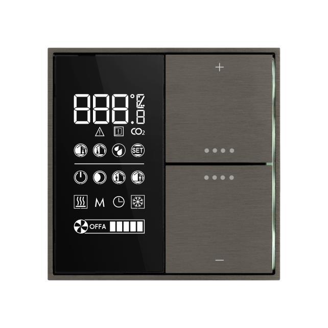
15 4 User interface The user interface of the room temperature controller includes a LC-display, a pushbutton with two rockers and a series of freely programmable LEDs (4 for each rocker). The colour of the LEDs depend on the device version User interface: LC-display (1), rockers (2), LEDs (3) with lightguide The symbols on the rockers recall the function carried out: + temperature (or other parameters) increase; temperature (or other parameters) decrease; information sequence, operating mode change, ventilation control, seasonal change-over. Through a combined pressure of various symbols other functions can be carried out. 4.1 LCD-display The device is provided with a LC-display (1) with adjustable backlight that occupies a vertical area of approx. 40 x 80 mm (WxH) in the left half of the device Information displaying Depending on the configuration done with ETS, the connections and the availability of information (local or received from the bus), the series of symbols allow to display: room actual temperature (it may be the temperature calculated using a weighted average of two values); outdoor temperature, preceded by a (minus) sign in case of outdoor temperature below 0 C; relative humidity (in %, without decimals); perceived temperature (estimated with the measured values of temperature and relative humidity); temperature setpoint (for the actual operating mode); concentration of CO2 (in ); alarm and error condition (A01, A02 E01, E02 ); window opening; EKINEX S.p.A. - All rights reserved Page 15
16 operating mode (comfort / standby / economy / building protection); seasonal mode (heating / cooling); device status calling / not calling (or setpoint reached / not reached); operation in manual mode (M); operation as slave device (clock); fan status (1-2-3-automatic-off), when present; device physical address assigned by ETS. Display symbols Digits (for numeric values display) Economy operating mode (night) Celsius degrees Standby operating mode Fahrenheit degrees Comfort operating mode Percentage (relative humidity) Per mille (only for CO 2 concentration) Heating mode active (device not calling or setpoint reached) Heating mode active (device calling or setpoint not reached) Alarm Window opening Carbon-dioxide (CO 2) Indoor temperature Manual operation (M) Slave (operation subordinated to a supervising KNX device) Cooling mode active (device not calling or setpoint reached) Cooling mode active (device calling or setpoint not reached) Outdoor temperature OFF (fan-coil switched off) Relative humidity SET Automatic fan-coil operation (example: speed 3) Manual fan-coil operation (example: speed 2) Building protection operating mode (off) Symbols that can be activated on the LC-display Segment test The segment test allows you to check at any time the proper functionality of the display. In order to do the test, press simultaneously + (plus) on the upper rocker and the symbol on the lower rocker for more EKINEX S.p.A. - All rights reserved Page 16
 without pressing a button, the device will return to the previous situation. 4.1.")
17 than 3 seconds. All symbols are activated simultaneously; then all the symbols are turned off. In the test phase keep available the instructions or the user guide. If you elapse the time set in the parameter "Time to exit change without saving" (General folder) without pressing a button, the device will return to the previous situation Backlight The backlight intensity of the LC-display is adjustable. The first setting is done when configuring the device using ETS, but the intensity can be changed later at any time. To access the change press simultaneously + (plus) and (bothon the upper rocker) for more than 3 seconds. All symbols are turned off except the digits and the percentage symbol. The actual value (as a percentage) of backlight intensity is displayed. At each pressing of + or the intensity is increased or decreased by 5%. To confirm the selected intensity press shortly (< 3 seconds) the symbol either on the upper rocker. Three rapid flashes of the digits indicate that the new value was saved. If you elapse of time interval set in the "Time to exit change without saving " (General folder) without pressing any rocker, the device returns to the previous situation. 4.2 Rockers The pushbutton with two rockers integrated in the device controls the functions of the thermostat. The set of two rockers has to be ordered separately; the symbols on the rockers of the set are pre-defined and cannot be changed. The areas marked by the symbols + (plus) and (minus) allow you to change a setting (e.g. the temperature setpoint), while those marked by the symbol allow you to display a sequence of information, to change the operating mode, to control the ventilation, to do the seasonal change-over (heating to cooling and vice versa) or to confirm a setting change. The part number of the set EK-TSQ-Gxx-EP2 must be completed with the part (xx) that identifies the material, color and finishing; for the exact code please refer also to the latest edition of the ekinex product catalog or the website Rockers use Upper rocker Lower rocker Functions for room temperature controlling + and and EKINEX S.p.A. - All rights reserved Page 17
18 5 Sensors The room temperature controller is equipped with three sensors: temperature (1); relative humidity (2). 2 1 Position of the sensors: temperature (1), relative humidity (2). The temperature sensor (not to be seen in the drawing) is located under the plastic half-shell for the rockers mounting. 5.1 Temperature sensor The integrated temperature sensor allows the measureming of the room temperature in the range from 0 C to +40 C with a resolution of 0.1 C. To keep into account significant environmental interferences such as the proximity to heatsources, the installation on an outer wall, the chimney effect due to rising warm air through the corrugated tube connected to the wall-mounting box, the measured value can be corrected by means of a offset of ± 5 C or, preferably, can be used a weighted average between two values of temperature chosen from the following ones: value measured by the integrated sensor, value measured by a temperature sensor connected to one of the inputs of the device, value received via bus from another KNX device (such as ekinex pushbuttons). 5.2 Relative humidity sensor The integrated relative humidity sensor allows the measuring of the relative humidity value in the room. The measured value allows you to make an advanced room thermoregulation and enlarge the opportunities for a safe operation of certain types of terminal equipments used for cooling. The measured value can also be sent on the bus via the 114 (1 byte) and the 115 (2 bytes) Communication Objects.By means of a calculation performed by the thermostat, on the bus can also be sent psychrometric values obtained from the combined measurement of temperature and humidity, such as the dew-point temperature, as well as the index of perceived temperature (only in summer mode). EKINEX S.p.A. - All rights reserved Page 18
19 6 Input variables The data that the device usesin its control algorithms and /or to be displayed may come from: the internal sensors; sensors or digital signals connected to the two physical inputs of the device; the KNX bus through standard Communication Objects. The processed data can also be transmitted on the KNX bus as Communication Objects.The classification of the input variables is shown in the following table. Data Coming from Description Room temperature Analogic value for thermoregulation functions Internal sensor Room relative humidity Analogic value for thermoregulation functions Window state (open/close) [DI] window contact sensor Card holder state (badge in/out) [DI] card holder contact sensor Presence of condensation [DI] anticondensation sensor Conveying fluid temperature at the exchange coil Input 1 or 2 (device [AI] coil battery temperaure sensor Room temperature (for weighted average value) terminals) [AI] room temperature sensor Room temperature (other measurement height) configurated [AI] antistratification temperature sensor Floor surface temperature [AI] floor surface temperature sensor Outdoor temperature [AI] outdoor temperature sensor Further temperature value [AI] generic (NTC) temperature sensor Room temperature Object 34 (2 bytes) Room relative humidity Objects 35 (2 bytes) and 36 (1 byte) Antistratification temperature Object 37 (2 bytes) Outdoor temperature Object 38 (2 bytes) CO 2 concentration (air quality) Object 39 (2 bytes) Conveying fluid temperature at the exchange coil KNX bus (through Object 40 (2 bytes) communication Floor surface temperature objects) Object 41 (2 bytes) Conveying fluid flow temperature Object 42 (2 bytes) Presence of condensation Object 46 (1 bit) Window state (open/close) Objects 43 and 44 (1 bit) Presence of people in the room Objects 32 and 33 (1 bit) Card holder state (badge in/out) Object 45 (1 bit) Input variables from internal sensors, physical inputs and standard communication objects. The device does not have outputs for direct switching or control of heating/cooling terminals or for status or values signalling. The output variables include exclusively communication objects that are sent on the bus, received and processed by KNX actuators (general-purpose or dedicated to HVAC applications). EKINEX S.p.A. - All rights reserved Page 19
20 7 Application program for ETS In the following chapters there is the list of folder, parameters and communication objects of the application program. Some specific functions of the thermostat are described in more detail in the dedicated paragraphs. The tree structure of the application program as imported into ETS (or by pressing the "Default Parameters" button of ETS) is the following: About EK-EQ2-TP General Internal sensors Temperature sensor Inputs External sensors ( from bus) LCD display Led Temperature control Settings Heating Relative humidity control Comfort Energy saving Windows contacts Presence sensors Card holder Other folders may appear depending on the choices done for the parameters of the folders represented in the main tree structure. 7.1 About EK-EQ2-TP The folder About EK-EQ2-TP is for information purposes only and does not contain parameters to be set. The information given is: Copyright EKINEX S.p.A Application software for ETS4 Version 2.00 (or later) KNX room temperature controller with LC-display and humidity sensor EKINEX S.p.A. Via Circonvallazione s/n I Miasino (NO) Italy EKINEX S.p.A. - All rights reserved Page 20
21 General The General folder includes the following parameters: Device operation as Temperature displayed unit Default displayed information Time to return to default display information Button function level Time to exit change without saving Delay after bus voltage recovery The folder has no secondary folders Parameters Parameter name Conditions Values Device operation as Temperature displayed unit stand-alone stand-alone/chrono slave If configured as stand-alone/chrono the operating mode can be selected manually on the device; in that way, the commands received via bus are ignored. If changing the operating mode the watch symbol is selected, the commands received via bus are accepted again. If configured as slave, the room temperature controller receives from a KNX device (acting as supervisor) HVAC modes, setpont values, etc. Celsius Fahrenheit Default displayed information Time to return to default display information Button function level Time to exit change without saving actual temperature temperature setpoint The actual temperature is the value by which the device performs the temperature regulation. It may be the value measured from a single sensor (internal, from the bus or from an input) or the weighted average of the temperatures measured by a main sensor and an additional sensor. The displayed setpoint temperature is that of the operating mode currently set on the room temperature controller (deduced from the symbol on). 5 s [other values in the range 10 s 1 min] Time interval after which the display automatically switches between the manually recalled information to the default information. end user system integrator This parameter allows you to partially inhibit the functions that can be recalled using the rockers. 8 s [other values in the range 2 s 12 s] Time interval without further pressing of the rockers at the end of which the device exits the procedure without saving the current changes. EKINEX S.p.A. - All rights reserved Page 21
22 Parameter name Conditions Values Delay after bus voltage recovery 00:00: hh:mm:ss:fff [range 00:00: :10:55.350] Time interval after which the transmission of the telegrams on the bus starts after the power supply is restored. The delay affects both the event-driven transmission and the cyclic transmission of a telegram. Regarding the latter, the counting of the pause interval for retransmission starts at the end of the time of initial delay. The field has format hh:mm:ss:fff (hours : minutes : seconds.milliseconds): the default value 00:00: corresponds to 4 seconds. Logic functions disabled / enabled Enable tab to configure logic functions AND, OR, XOR 8-channel (4 inputs for channel) Information displayed as default One information between the actual temperature and the temperature setpoint is displayed preferably by the digits of the display. The device allows you to retrieve and display a series of other information pressing the symbol on the upper rocker; after the time set in the parameter "Time to return to default information" without further pressure of, the display automatically returns to the default information. Functional level of the rockers The use of the rockers for controlling the room temperature controller can be partially inhibited in the configuration phase through a filter for the access to the several functions. When using the rockers a distinction is made between: first level functions (= short or long pressing of the rockers) for the end user; second level functions (= combination of rockers); to the first level are added a few functions for a system integrator or an installer. The enabled functional level is set through a special parameter. EKINEX S.p.A. - All rights reserved Page 22
23 7.2 Internal sensors The Internal sensors folder includes the following parameters: Temperature sensor Relative humidity sensor Parameters Parameter name Conditions Values Temperature sensor Relative humidity sensor enabled disabled The temperature sensor is enabled as default. When the sensor is disabled, the corresponding folder disappears from the main tree structure of the application program; in this case to have available again the functions for Temperature control you have to enable Room temperature in the External sensors (from bus) folder or set Input X = [AI] temperature sensor (X = 1, 2) in the Inputs folder. disabled enabled The relative humidity sensor is disabled as default. When the sensor is disabled, the functions that require the value of relative humidity are available only if you enable Relative humidity in the External sensors (from bus) folder. When the sensor is enabled, the corresponding folder appears in the main tree structure of the application program Temperature sensor The Temperature sensor secondary folder appears only if the corresponding sensor is enabled in the folder Internal sensors and includes the following parameters: Filter type Temperature offset Minimum change of value to send [K] Cyclic sending interval Threshold 1 Threshold Parameters and communication objects Parameter name Conditions Values Filter type Temperature offset Temperature sensor = enabled Low = average value every 4 measurements Medium = average value every 16 measurements High = average value every 64 measurements Temperature sensor = enabled low medium high 0 C [range -5 C +5 C] Minimum change of value to send [K] 0,5 Temperature sensor = enabled [range 0 5] If the parameter is set to 0 (zero),no value is sent after a change. EKINEX S.p.A. - All rights reserved Page 23
24 Parameter name Conditions Values Cyclic sending interval Temperature sensor = enabled no sending [other values in the range 30 s 120 min] Threshold 1 Temperature sensor = enabled not active below above Value [ C] Temperature sensor = enabled, Threshold 1 = below or above 7 [range 0 50] Threshold 2 Temperature sensor = enabled not active below above Value [ C] Temperature sensor = enabled, Threshold 2 = below or above 45 [range 0 50] Hysteresis Temperature sensor = enabled, Threshold 1 and/or Threshold 2 = below or above 0,4 K [other values between 0,2 K and 3 K] Cyclic sending interval Temperature sensor = enabled, Threshold 1 and/or Threshold 2 = below or above no sending [other values in the range 30 s 120 min] Object name Conditions Dim. Flags DPT Temperature value Temperature sensor = enabled 2 Bytes CR-T-- [9.001] temperature ( C) Comm. Obj. No. 3 Temperature threshold1 - Switch Temperature sensor = enabled, Threshold 1 = below or above 1 Bit CR-T-- [1.001] switch 16 Temperature threshold 2- Switch Temperature sensor = enabled, Threshold 2 = below or above 1 Bit CR-T-- [1.001] switch 17 Acquisition filter The acquisition filter calculates an average with a series of measured values before sending on the bus. The parameter can have the following values: low = average value every 4 measurements; medium = average value every 16 measurements; high = average value every 64 measurements. Correction of the measured temperature The sampling of the temperature value occurs every 10 seconds, while the display is updated every minute. During the configuration with ETS the opportunity is given to correct the measured temperature value within the offset range of - 5 C C (step: 0.1 C). EKINEX S.p.A. - All rights reserved Page 24
25 7.2.3 Relative humidity sensor The secondary folder Relative humidity sensor appears only if the corresponding sensor is enabled in the folder Internal sensors and includes the following parameters: Filter type Minimum change of value to send [%] Cyclic sending interval Threshold 1 Threshold 2 For single parameters are valid the indications given for the same parameters of the temperature sensor. The folder of the relative humidity sensor does not have a parameter correction value (offset); the humidity sensor used is calibrated at the factory Parameters and communication objects Parameter name Conditions Values Filter type Minimum change of value to send [%] Cyclic sending interval Relative humidity sensor = enabled Low = average value every 4 measurements Medium = average value every 16 measurements High = average value every 64 measurements Relative humidity sensor = enabled low medium high 2 [range 0 10] If the parameter is set to 0 (zero), no value is sent after a change. Relative humidity sensor = enabled no sending [other values in the range 30 s 120 min] Threshold 1 Relative humidity sensor = enabled not active below above Value [%] Relative humidity sensor = enabled, Threshold 1 = below or above 65 [range 0 100] Threshold 2 Relative humidity sensor = enabled not active below above Value [%] Relative humidity sensor = enabled, Threshold 2 = below or above 65 [range 0 100] Hysteresis [%] Cyclic sending interval Relative humidity sensor = enabled, Threshold 1 or Threshold 2 = below or above 3,0 % [other values in the range 0,5 4,0 %] The value of the parameter Hysteresis is common for both parameters Threshold 1 and Threshold 2. Relative humidity sensor = enabled, Threshold 1 or Threshold 2 = below or above no sending [other values in the range 30 s 120 min] The value of the parameter Cyclic sending interval is common for both parameters Threshold 1 and Threshold 2. EKINEX S.p.A. - All rights reserved Page 25
26 Object name Conditions Dim. Flags DPT Humidity value (1 byte) Relative humidity sensor = enabled, Dimension of the C. O. = 1 byte 1 Byte CR-T-- [5.001] percentage (0..100%) Comm. Obj. No. 14 Humidity value (2 byte) Relative humidity sensor = enabled, Dimension of the C. O. = 2 Byte 2 Byte CR-T-- [9.007] percentage (%) 15 Temperature threshold 1 - switch Relative humidity sensor = enabled, Threshold 1 = below or above 1 Bit CR-T-- [1.001] switch 18 Temperature threshold 2 - switch Relative humidity sensor = enabled, Threshold 2 = below or above 1 Bit CR-T-- [1.001] switch 19 EKINEX S.p.A. - All rights reserved Page 26
27 7.3 Inputs The folder Inputs allows you to configurate one or two variables (either digital or analogic) depending on the digital signals or the temperature sensors connected to the terminal blocks of the inputs. The physical values or the detected states can be used locally by the device for temperature control functions and/or transmitted on the bus for other purposes. The folder includes the parameters for configuring independently the inputs 1 and 2. The two inputs are identical; for simplicity in the following only parameters and communication objects of a single input are described Input X The folder Input X (X = 1, 2) includes the following parameters: Input X Contact type Filter type Temperature offset Cyclic sending interval Minimum change of value to send (K) Threshold 1 Value [ C] Threshold 2 Value [ C] Hysteresis Cyclic sending interval Parameters and communication objects Parameter name Conditions Values Input X Contact type Debounce time disabled [DI] window contact sensor [DI] card holder contact sensor [DI] anticondensation sensor [AI] coil battery temperature sensor [AI] room temperature sensor [AI] antistratification temperature sensor [AI] floor surface temperature sensor [AI] outdoor temperature sensor [AI] generic (NTC) temperature sensor The [DI] prefix indicates a digital input, the [AI] prefix an analogic input. Input X = [DI] NO (normally open) NC (normally closed) This parameter is always available when the input is configured as digital. Input X = [DI] 00:00: hh:mm:ss.fff [range 00:00: :10:55.350] This parameter is always available when the input is configured as digital. The field has format hh:mm:ss:fff (hours : minutes : seconds. milliseconds): the default value 00:00: corresponds to 200 milliseconds. EKINEX S.p.A. - All rights reserved Page 27
28 Parameter name Conditions Values Filter type Input X = [AI] low medium high This parameter is always available when the input is configured as analogic. Low = average value every 4 measurements Medium = average value every 16 measurements High = average value every 64 measurements Offset temperature Input X = [AI] 0 C [range -5 C +5 C] This parameter is always available when the input is configured as analogic. Minimum change of value to send [K] 0,5 [range 0 5] This parameter is always available when the input is configured as analogic. When set to 0 (zero), no value is sent at a change. Cyclic sending interval Input X different from disabled no sending [other values in the range 30 s 120 min] Threshold 1 Input X = [AI] not active / below / above This parameter is always available when the input is configured as analogic. Vaue [ C] Input X = [AI] Threshold 1 = below or above 7 [range 0 50] Threshold 2 Input X = [AI] not active / below / above This parameter is always available when the input is configured as analogic. Value [ C] Input X = [AI] Threshold 2 = below or above 45 [range 0 50] Hysteresis Input X = [AI] Threshold 1 = below or above Threshold 2 = below or above 0,4 K [other values in the range 0,2 K 3 K] Cyclic sending interval Input X = [AI] Threshold 1 = below or above Threshold 2 = below or above no sending [other values in the range 30 s 120 min] Object name Conditions Dim. Flags DPT Window contact sensor (from input 1) Input 1 = [DI] windows contact sensor Comm. Obj. No. 1 Bit CR-T-- [1.019] window/door 26 Window contact sensor (from input 2) Anticondensation sensor (from input 1) Input 2 = [DI] windows contact 1 Bit CR-T-- [1.019] window/door 27 sensor If both inputs (1 and 2) are configured in the same way, only the first one is used by the device. Input 1 = [DI] anticondensation 1 Bit CR-T-- [1.005] alarm 28 sensor Anticondensation sensor (from input 2) Card holder contact sensor (from input 1) Input 2 = [DI] anticondensation 1 Bit CR-T-- [1.005] alarm 29 sensor If both inputs (1 and 2) are configured in the same way, only the first one is used by the device. Input 1 = [DI] card holder contact 1 Bit CR-T-- [1.018] occupancy 30 sensor Card holder contact sensor Input 2 = [DI] card holder contact 1 Bit CR-T-- [1.018] occupancy 31 EKINEX S.p.A. - All rights reserved Page 28
29 Object name Conditions Dim. Flags DPT Comm. Obj. No. (from input 2) sensor If both inputs (1 and 2) are configured in the same way, only the first one is used by the device. Coil battery temperature sensor (from input 1) Input 1 = [AI] coil battery temperature sensor 2 Byte CR-T-- [9.001] temperature ( C) 20 Coil battery temperature sensor (from input 2) Input 2 = [AI] coil battery temperature sensor 2 Byte CR-T-- [9.001] temperature ( C) If both inputs (1 and 2) are configured in the same way, only the first one is used by the device. 23 Temperature value sensor (from input 1) Input 1 = [AI] room temperature sensor 2 Byte CR-T-- [9.001] temperature ( C) 20 Temperature value sensor (from input 2) Input 2 = [AI] room temperature sensor 2 Byte CR-T-- [9.001] temperature ( C) 23 Antistratification temperature sensor (from input 1) If both inputs (1 and 2) are configured in the same way, only the first one is used by the device. Input 1 = [AI] antistratification 2 Byte CR-T-- [9.001] temperature C 20 temperature sensor Antistratification temperature sensor (from input 2) Floor surface temperature sensor (from input 1) Input 2 = [AI] antistratification 2 Byte CR-T-- [9.001] temperature C 23 temperature sensor If both inputs (1 and 2) are configured in the same way, only the first one is used by the device. Input 1 = [AI] floor surface 2 Byte CR-T-- [9.001] temperature C 20 temperature sensor Floor surface temperature sensor (from input 2) Outdoor temperature sensor (from input 1) Input 2 = [AI] floor surface 2 Byte CR-T-- [9.001] temperature C 23 temperature sensor If both inputs (1 and 2) are configured in the same way, only the first one is used by the device. Input 1 = [AI] outdoor 2 Byte CR-T-- [9.001] temperature C 20 temperature sensor Outdoor temperature sensor (from input 2) Temperature value sensor (from input 1) Input 2 = [AI] outdoor 2 Byte CR-T-- [9.001] temperature C 23 temperature sensor If both inputs (1 and 2) are configured in the same way, only the first one is used by the device. Input 1 = [AI] generic (NTC) 2 Byte CR-T-- [9.001] temperature C 20 temperature sensor Temperature value sensor (from input 2) Temperature threshold 1 sensor 1 - Switch Input 2 = [AI] generic (NTC) temperature sensor 2 Byte CR-T-- [9.001] temperature C 23 If both inputs (1 and 2) are configured in the same way, only the first one is used by the device. Input 1 = [AI] Threshold 1 = below or above, 1 Bit CR-T-- [1.001] switch 21 Threshold 2 = below or above Temperature threshold 2 sensor 1 - Switch Input 1 = [AI] Threshold 1 = below or above, Threshold 2 = below or above 1 Bit CR-T-- [1.001] switch 22 EKINEX S.p.A. - All rights reserved Page 29
30 Object name Conditions Dim. Flags DPT Temperature threshold 1 sensor 2 - Switch Input 2= [AI] Threshold 1 = below or above, Threshold 2 = below or above Comm. Obj. No. 1 Bit CR-T-- [1.001] switch 24 Temperature threshold 2 sensor 2 - Switch Input 2= [AI] Threshold 1 = below or above, Threshold 2 = below or above 1 Bit CR-T-- [1.001] switch 25 EKINEX S.p.A. - All rights reserved Page 30
31 7.4 External sensors (from bus) As external sensors are intended KNX-devices (or conventional sensors interfaced to the bus through KNX devices) which send states or values to the room temperature controller via the bus. Enabling an external sensor, without connecting the corresponding communication object, generates a permanent alarm on the display and suspends the thermoregulation function. The folder External sensors (from bus) includes the following parameters: Room temperature Antistratification temperature Outdoor temperature Air quality Floor surface temperature Flow temperature Anticondensation Window contact X (X = 1, 2) Presence sensor X (X = 1, 2) Card holder contact Analog sensor timeout Digital sensor timeout The folder does not have any secondary folder Parameters and communication objects Parameter name Conditions Values Room temperature disabled / enabled It enables a bus temperature sensor. The measured value can be used to calculate a weighted average value in combination with the temperature sensor integrated into the device or a temperature sensor connected to a device input. Relative humidity Internal sensors Relative humidity sensor = disabled disabled / enabled It enables a relative humidity bus sensor to be used alternatively to the sensor integrated into the device. Humidity C.O. dimension Relative humidity = enabled 1 byte (DPT 5.001) 2 bytes (DPT 9.007) Antistratification temperature Outdoor temperature Air quality Coil temperature disabled / enabled It enables a temperature bus sensor to carry out the antistratification function. disabled / enabled It enables an outdoor temperature bus sensor to display the measured value on the display. This is alternative to an outdoor temperature sensor connected to a device input: the parameter appears only if the external temperature sensor is disabled in the Inputs folder. disabled / enabled It enables an air quality bus sensor to display the measured value (CO 2 concentration) on the display. disabled / enabled It enables a bus sensor for measuring the conveying fluid temperature at the coil for heat exchange. The acquisition of the value allows realizing the hotstart function of a fan. EKINEX S.p.A. - All rights reserved Page 31
32 Parameter name Conditions Values Floor surface temperature disabled / enabled It enables a bus sensor for measuring the surface temperature of a floor heating system. The acquisition of the value allows to realize the function of surface temperature limitation. Flow temperature disabled / enabled It enables a bus sensor for measuring theconveying fluid temperature. The acquisition of the value is used to calculate the dew-point temperature and to realize the function of protection from condensation of activetype in surface (floor or ceiling) cooling systems. 00:05:00hh:mm:ss Analogic sensors timeout [range 00:00:00 18:12:15] The field has format hh:mm:ss (hours : minutes : seconds): the default value 00:05:00 corresponds to a timeout of 5 minutes. The value 00:00:00 means that the timeout of the analogic sensors is disabled. Anticondensation disabled / enabled It enables a bus sensor for detecting the condensation. Window contact 1 disabled / enabled It enables a bus sensor for detecting the state of opening / closing of a window or a door. Window contact 2 disabled / enabled It enables a bus sensor for detecting the state of opening / closing of a window or a door. Presence sensor 1 disabled / enabled It enables a bus sensor for detecting the presence / absence of people within a room. Presence sensor 2 disabled / enabled It enables a bus sensor for detecting the presence / absence of people within a room. Card holder contact disabled / enabled It enables a bus sensor for detecting the presence / absence of people in a hotel room provided with a card holder. 00:05:00hh:mm:ss Digital sensors timeout [range 00:00:00 18:12:15] The field has format hh:mm:ss (hours : minutes : seconds): the default value 00:05:00 corresponds to a timeout of 5 minutes. The value 00:00:00 means that the timeout of the digital sensors is disabled. Object name Conditions Dim. Flags DPT Room temperature (from bus) enabled 2 Byte C-W--- [9.001] temperature ( C) Comm. Obj. No. 34 Humidity (2 bytes, from bus) Relative humidity sensor = enabled, Humidity C.O. dimension = 2 bytes 2 Byte C-W--- [9.007] percentage (%) 35 Humidity (1 byte, from bus) Relative humidity sensor = enabled, Humidity C.O. dimension = 1 byte 1 Byte C-W--- [5.001] percentage (0..100%) 36 Antistratification temperature (from bus) enabled 2 Byte C-W--- [9.001] temperature ( C) 37 EKINEX S.p.A. - All rights reserved Page 32
33 Object name Conditions Dim. Flags DPT Outdoor temperature (from bus) enabled 2 Byte C-W--- [9.001] temperature C Comm. Obj. No. 38 Air quality (from bus) enabled 2 Byte C-W--- [9.008] parts/million (ppm) 39 Coil temperature (from bus) enabled 2 Byte C-W--- [9.001] temperature ( C) 40 Floor temperature (from bus) enabled 2 Byte C-W--- [9.001] temperature ( C) 41 Flow temperature (from bus) enabled 2 Byte C-W--- [9.001] temperature ( C) 42 Anticondensation (from bus) enabled 1 Bit C-W--- [1.001] switch 46 Windows contact sensor 1 (from bus) enabled 1 Bit C-W--- [1.019] window/door 43 Windows contact sensor 2 (from bus) enabled 1 Bit C-W--- [1.019] window/door 44 Presence sensor 1 (from bus) enabled 1 Bit C-W--- [1.018] occupancy 32 Presence sensor 2 (from bus) enabled 1 Bit C-W--- [1.018] occupancy 33 Contact of card holder (from bus) enabled 1 Bit C-W--- [1.001] switch 45 About the sensor timeout The system of internal control of the thermostat monitors cyclically the updating status of the values of the external sensors (from bus) and the inputs when the timeout setting expires. In case no updated value has been received, the regulation function is suspended, an alarm is displayed on the display through the symbol and the corresponding alarm code (see also the list of alarms in the paragraph Diagnostics). EKINEX S.p.A. - All rights reserved Page 33
34 7.5 Weighted temperature value The Weighted temperature value folder appears only if two sensors for measuring the room temperature are enabled and includes the following parameters: Main source for temperature value Additional source temperature value Relative weight Minimum change of value to send [K] Cyclic sending interval Parameters and communication objects Parameter name Conditions Values Main source for temperature value * *) The values that can be set depend on enabling the internal sensor, the inputs or the external sensors (from bus). Additional source temperature value * *) The values that can be set depend on enabling the internal sensor, the inputs or the external sensors (from bus). 100% main sensor 90% / 10% 80% / 20% 70% / 30% 60% / 40% Relative weight 50% / 50% 40% / 60% 30% / 70% 20% / 80% 10% / 90% 100% additional sensor Minimum change of value to send [K] Cyclic sending interval 0,5 [other values in the range 0 5 K] If the parameter is set to 0 (zero), no value is sent at the change. no sending [other values in the range 30 s 120 min] Object name Conditions Dim. Flags DPT Weighted temperature Cyclic sending interval different than no sending 2 Byte CR-T-- [9.001] temperature C Comm. Obj. No. 47 About the weighted temperature The device allows the acquisition of the room temperature in three ways: 1) from the temperature sensor integrated in the device; 2) from an external temperature sensor connected to a device input configured as analogic (Inputs Input 1 or 2 = [AI] room temperature sensor); 3) via bus from another KNX device, e.g. from an ekinex pushbutton (External sensors (from bus) Room temperature = enabled); EKINEX S.p.A. - All rights reserved Page 34
35 To optimize or correct the room temperature regulation in special cases (in large rooms, in presence of strong asymmetry of the temperature distribution, when the installation of the device is in a position not suitable, etc.), the device can then use a weighted average between two temperature values. The weights are assigned by the parameter Relative weight that assigns a ratio of the two values. EKINEX S.p.A. - All rights reserved Page 35
36 7.6 LCD-display The folder LCD display includes the following parameters: Backlight intensity Automatic backlight dimming Energy saving Visualisation type Time before energy saving mode Backlight when in energy saving mode Behaviour on button press Actual temperature (always displayed) Temperature setpoint Perceived temperature Relative humidity Relative humidity setpoint Air quality Energy saving mode After a configurable time interval, the room temperature controller switches from normal to energy saving operation. In this display mode: the backlight intensity may be reduced; the information content to be displayed may be reduced (two options: partial and temperature only). Backlight The default backlight of the display can be configured according to the installation location and light conditions of the room. The backlight intensity can be set to a fixed value (in %). Information to be displayed The actual temperature is always displayed; in addition, and depending on individual preferences, other information can be displayed in sequence: the setpoint temperature (for the current operating mode), the perceived temperature, the relative humidity, the relative humidity setpoint and the air quality Parameters Parameter name Conditions Values Backlight intensity 10% / 20% / 30% / 40% / 50% / 60% / 70% / 80% / 90% / 100% Energy saving disabled / enabled If the parameter Energy saving = enabled, after a certain time interval the device automatically reduces the backlight intensity and possibly the information content displayed. Visualisation type Time before energy saving mode Energy saving = enabled full temperature only In addition to the digits, temperature only includes the symbol ( C or F). Energy saving = enabled 10 s / 15 s / 30 s 45 s / 1 min EKINEX S.p.A. - All rights reserved Page 36
37 Parameter name Conditions Values Backlight when in energy saving mode Energy saving = enabled off / 2% / 5% / 10% / 15% / 20% / 25% / 30% Behaviour on button press Temperature setpoint Energy saving = enabled backlight only backlight and button function It defines the reaction at the first press of a rocker when the device is in energy saving mode. At least one temperature sensor enabled (internal, external from bus, from an input) enable / disabled Perceived temperature A temperature sensor and a relative humidity sensor enabled (internal, external from bus, from an input) enable / disabled Relative humidity At least one relative humidity sensor enabled (internal or external from bus) enable / disabled Relative humidity setpoint At least one relative humidity sensor enabled (internal or external from bus) enable / disabled Air quality External sensors (from bus) Air quality = enabled enable / disabled EKINEX S.p.A. - All rights reserved Page 37
38 7.7 Leds Each pushbutton channel has four programmable leds; for example, for status feedback of the controlled loads or for orientation nightlight. The light emitted by the leds is diffused by means of an appropriate lightguide. The folder Led includes the following parameters: Leds intensity from bus Leds intensity Led first colour XY (X = 1, 2; Y= A, B) Led second colour XY (X = 1, 2; Y= A, B) Off delay Always Blinking Blinking period / type Signal from bus Technical alarm Parameters and communication objects Parameter name Conditions Values Leds intensity from bus Leds intensity Led first colour XY Off delay no / yes It enables receiving from the bus of the light intensity value emitted by the leds. Leds intensity from bus = no 50% [range 0% 100%] It allows setting the light intensity value emitted by the leds (if not received from the bus). X = 1, 2; Y= A, B Led first colour XY = when contact close fixed when contact close status from bus 00:00:02:00 hh:mm:ss:ff [other values in the range 00:00:00:00 01:49:13:50] Always Led first colour XY = fixed off / on Blinking Led first colour XY = status from bus no / yes Blinking period / type Led first colour XY = status from bus, Blinking = yes 0,25 s on / 0,25 s off 0,25 s on / 0,75 s off 0,5 s on / 0,5 s off 0,75 s on / 0,25 s off 0,5 s on / 1,5 s off 1 s on / 1 s off 1,5 s on / 0,5 s off 1 s on / 3 s off 2 s on / 2 s off 3 s on / 1 s off Signal from bus Led first colour XY = status from bus not inverted / inverted EKINEX S.p.A. - All rights reserved Page 38
39 Parameter name Conditions Values Led second colour XY fixed when contact close status from bus X = 1, 2; Y= A, B 00:00:02:00 Off delay [other values in the range 00:00:00: :50] Value in hh:mm:ss:ff. Always Led second colour XY = fixed off / on Blinking Led second colour XY = status from bus no / yes Blinking period / type Led second colour XY = status from bus, Blinking = yes 0,25 s on / 0,25 s off 0,25 s on / 0,75 s off 0,5 s on / 0,5 s off 0,75 s on / 0,25 s off 0,5 s on / 1,5 s off 1 s on / 1 s off 1,5 s on / 0,5 s off 1 s on / 3 s off 2 s on / 2 s off 3 s on / 1 s off Signal from bus Led second colour XY = status from bus not inverted / inverted Technical alarm disabled / enabled It enables the communication object nr. 0 "Technical alarm" that allows to activate an alarm signal via a bus telegram. The flashing led indicates that the alarm condition is active. Object name Conditions Dim. Flags DPT Comm. Obj. No. Technical alarm 1 Bit C--W- [1.005] alarm 0 Leds intensity percentage Leds intensity from bus = yes 1 Bit C--W- [5.001] percentage 2 Rocker X- Led first colour A Led first colour XA = status from bus 1 Bit CRWTU- [1.001] switch 6 (X = 1) 10 (X = 2) Rocker X- Led second colour A Led second colour XA = status from bus 1 Bit CRWTU- [1.001] switch 7 (X = 1) 11 (X = 2) Rocker X- Led first colour B Led first colour XB = status from bus 1 Bit CRWTU- [1.001] switch 8 (X = 1) 12 (X = 2) Rocker X- Led second colour B Led second colour LED XB = status from bus 1 Bit CRWTU- [1.001] switch 9 (X = 1) 13 (X = 2) EKINEX S.p.A. - All rights reserved Page 39
40 7.8 Temperature control The Temperature control folder includes the following secondary folders: Settings Heating Cooling Ventilation Scenes The Cooling and Ventilation secondary folders appear only if in the Settings folder the parameter Thermostat function is set to the value both heating and cooling or cooling. The Scenes secondary folder appears only if in the Settings secondary folder the parameter Scenes is set to the value enabled Settings The Settings folder includes the following parameters: Thermostat function Command Communication Object Heating cooling switchover Setpoint Cyclic sending interval Max manual temperature change Saving timeout (manual change) End of manual operation Max setpoint temperature change Scenes Valve protection function Frequency Time interval Parameters and communication objects Parameter name Conditions Values Thermostat function heating cooling both heating and cooling Command Communication Object Thermostat function = both heating and cooling separated / unique Heating cooling switchover Thermostat function = both heating and cooling manual from bus automatic Heating-cooling switchover cyclic sending interval Thermostat function = both heating and cooling no sending [other values in the range 30 s 120 min] EKINEX S.p.A. - All rights reserved Page 40
41 Parameter name Conditions Values no sending Setpoint cyclic sending interval [other values in the range 30 s 120 min] The setpoint value that can be sent cyclically is the actual one, depending on the operating mode set manually by the user or automatically by another KNX supervising device with the possibility of time scheduling. The actual setpoint value takes also into account the actual state of the contacts window and presence detection (if the corresponding functions are enabled). not allowed, ± 1 C, ± 2 C, ± 3 C, ± 4 C, ± Max manual temperature change 5 C, ± 6 C, ± 7 C, ± 8 C, ± 9 C, ± 10 C It defines the maximum range allowed for the manual change of the temperature value. 6 s Saving timeout (manual change) [other values in the range 2s 12 s] It defines the time interval to wait for a confirmation of a manual change (see previous parameter). If the time interval elapses without confirmation, the device automatically returns to the previous state without saving the change. End of manual operation General Device operation as = stand-alone till first telegram from bus [other values in the range 30 min 48 h] Max setpoint temperature change Scenes not allowed, ± 1 C, ± 2 C, ± 3 C, ± 4 C, ± 5 C, ± 6 C, ± 7 C, ± 8 C, ± 9 C, ± 10 C It defines the maximum time allowed for changing the values of temperature setpoint in the several operating modes. disabled / enabled Valve protection function Frequency disabled / enabled It enables the function that activates the drive for the valve control during periods of inactivity of the system. Valve protection function = enabled once a day once a week once a month Time interval Valve protection function = enabled 10 s [other values in the range 5 s 20 min] Nome oggetto Conditions Dim. Flags DPT Comm. Obj. No. Actual setpoint 2 Byte CR-T-- [9.001] temperature ( C) 52 Heating/cooling status out Always visible 1 Bit CR-T-- [1.100] heating/cooling 48 The communication object is updated on the bus on event of change internally elaborated by the controller. The object is always exposed and contains the information about the current conduction mode of the internal temperature controller. [1.100] DPT Heat/Cool 1 Bit 0 = Cool 1 = Heating EKINEX S.p.A. - All rights reserved Page 41
42 Nome oggetto Conditions Dim. Flags DPT Comm. Obj. No. Heating/cooling status in Thermostat function = both heating and cooling; Heating cooling switchover = from bus 1 Bit C-W--- [1.100] heating/cooling 49 The communication object is received by the bus. All evento di commutazione i regolatori interni degli stadi primario e ausiliario (se abilitato) commutano il modo di conduzione. Il modo di conduzione attivo è segnalato dall apposito simbolo sul display. HVAC mode in 1 Byte C-W--- [20.102] HVAC mode 50 The device receives the operating mode (HVAC mode) from a bus device with function of supervisor. The operating mode received through this communication object can be later modified by the user (in questo caso il termostato ambiente passa in controllo manuale). HVAC forced mode in 1 Byte C-W--- [20.102] HVAC mode 51 The communication object allows to receive the operating mode similarly to what happens with the communication object HVAC mode; the difference is that the operating mode is received via this object (with the exception of the AUTO command) can not be subsequently modified by the user. The user can change the mode only after the forced HVAC mode has sent the AUTO command. HVAC mode out 1 Byte CR-T-- [20.102] HVAC mode 83 Building protection HVAC mode active 1 Bit CR-T-- [1.11] DPT_State 101 HVAC manual mode General Device operation as = standalone/chrono 1 Byte C-WTU- [20.102] HVAC mode 53 Chrono active status General Device operation as = standalone/chrono 1 Bit CR-T-- [1.011] state 54 Manual setpoint 2 Byte C-W--- [9.001] temperature ( C) 55 Manual/forced setpoint active status 1 Bit CRWTU- [1.011] state 56 EKINEX S.p.A. - All rights reserved Page 42
43 About the heating/cooling terminals The application functions of the room temperature controller configurable with ETS are particularly suitable for the control through general-purpose or dedicated KNX actuators of the following heating/cooling terminals: radiators; elettrical heaters; fancoils; radiant panels; dehumidification units; radiant panels + radiators (as auxiliary system); radiant panels + fancoils (as auxiliary system); radiant panels + dehumidification units Heating/cooling switchover The switchover between the two seasonal modes (heating / cooling) may happens as follows: 1) manually on the device by the end user; 2) automatically by the device; 3) from the KNX bus through a dedicated communication object. Manual switch-over (mode 1) The manual switch-over is suitable for bus systems with one or a limited number of room temperature controllers. If the devices have been configured for this purpose, the user does the switch-over manually on the device (that acts as a "master" for the switch-over function); the device sends on the bus the output communication object [DPT heat/cool] that switches possibly other room temperature controllers ("slave" devices) connected through a dedicated group address. Automatic switch-over (mode 2) The automatic switch-over is suitable for a 4-pipe hydraulic configuration of the heating/cooling installation (used e.g. for fan-coil units or ceiling radianti panels). Also in this case the information can be sent on the bus with the output communication object [DPT heat/cool]; the difference from the first mode is that switching is performed automatically on the basis of a comparison between the values of the actual temperature and the setpoint temperature. In this mode, the manual switching by the user is disabled. The automatic switch-over is realised with the introduction of a neutral zone according to the scheme in the picture below. OFF (protection) ECONOMY STAND-BY COMFORT 32 C 28 C 26 C 24 C Dead zone 20 C 18 C 8 C 16 C EKINEX S.p.A. - All rights reserved Page 43
44 Neutral zone and example of setpoint values correctly distributed Until the actual (measured) temperature is located below the setpoint value for the heating, the operation is heating; in the same way, if the actual value (measured) is greater than the setpoint value for the cooling, the mode is cooling. If the actual value (measured) temperature is within the dead zone, the previous mode of operation remains active; the switching point of the operation mode for heating / cooling must take place in correspondence with the current setpoint for the active HVAC, in the same way the switching cooling / heating must take place at the setpoint for heating. Switch-over via KNX bus (mode 3) The switch-over from the bus requires that the command is received from another KNX device, e.g. another room temperature controller or a Touch&See unit configured to this purpose. The other device works in this way as a supervisor device: the switch-over is triggered by the input communication object [DPT heat/cool]. In this mode the manual switch-over by an enduser is disabled. Thanks to this mode, the supervising device is able to control the slave devices with time-scheduled programs, extending their functionality to that of a chronothermostat (centrally controlled by the supervising device). The communication objects indicated in the block diagram allows monitoring and modifying the current conduction mode forced on the temperature controller. The object 48 Heating/cooling status out is always exposed, even when the thermostat function is set on heating or cooling only. When the function is set on both heating and cooling, the cyclic sending on bus can be enabled; anyway, the information about the actual conduction mode can be acquired with a reading request to this commiunication object. The object 49 Heating/cooling status in is exposed only when the function is both heating and cooling and the switching among the different modes is performed by the bus. 49 Heating/cooling status in [1.100] heating/cooling 48 Heating/cooling status out [1.100] heating/cooling Valve protection function The function is suitable for heating and cooling systems that use water as thermal conveying fluid and are provided with motorized valves for the interception of a zone or of a single room. Long periods of inactivity of the system can lead to the blockage of valves: to prevent this, the room temperature controller may periodically send a command to open / close the valve in the period of inactivity of the system. This possibility is made available in the application program by means of the parameter "Valve protection function", further defined by the frequency and duration of the valve control Remote Setpoint modification The communication objects shown in figure allow to monitor the Setpoint forced modifications performed locally by the user when interacting with the LCD display and the touch buttons of the room thermostat. The EKINEX S.p.A. - All rights reserved Page 44
45 communication objects (from now on: C.O.) also allow to perform the same modifications remotely, for example from a supervisor software. 55 Manual setpoint [9.001 temperature] 52 Actual setpoint [9.001 temperature] 56 Manual/forced setpoint active status [1.011 state] Those objects are about the Setpoint forced modification (symbol M on the LCD display): alternatively, the supervisor can act directly on the operating mode setpoints (C.O. with index 57-64). The value of the C.O Actual setpoint represents the current operative setpoint which the control algorithms are based on. The C.O. 56 Manual/forced setpoint active status indicates (read request mode) if the forced mode is active (symbol M on the LCD display present). The supervisor can force at any time the actual setpoint by writing a new value directly into the C.O. 55 Manual setpoint. The C.O. 56 Manual/forced setpoint active status can also be used in writing to exit the active forced mode Remote operative mode modification The communication objects shown in figure allow to monitor the operating mode (comfort, standy, economy and building protection) modifications performed locally by the user when interacting with the LCD display and the touch buttons of the room thermostat, or the operating mode forced by chrono program. The communication objects (from now on: C.O.) also allow to perform the same modifications remotely, for example from a supervisor software. 50 HVAC mode in [20.102] 53 HVAC manual mode [20.102] 83 HVAC mode out [20.102] 54 Chrono active status [1.011 state] The C.O. 50 HVAC mode in is associated to the chrono program. The C.O.s 83 HVAC mode out and 54 HVAC chrono active status allow the remote supervisor to discern the operating mode currently active on the room thermostat and also allow to understand if the chrono program is active or if attenuation is handled manually or not. The supervisor can set at any time a manual operating mode through C.O. 53 HVAC manual mode; to start the chrono program remotely, the C.O. 53 HVAC manual mode is to be set on value 0 = Automatic. EKINEX S.p.A. - All rights reserved Page 45
46 i The communication objects 53 HVAC manual mode and 54 HVAC chrono active status are available only if the room thermostat has the parameter Device operation as in the General folder set as stand-alone/chrono. EKINEX S.p.A. - All rights reserved Page 46
47 7.8.2 Heating The Heating folder includes the following parameters: Comfort temp. setpoint [ C] Standby temperature setpoint [ C] Economy temp. setpoint [ C] Building protection temp. setpoint [ C] Heating type Control type Hysteresis Cyclic sending interval Min. change of value to send [%] PWM cycle time Proportional band [0,1 K] Integral time [min] Floor temperature limitation Temperature limit [ C] Hysteresis [K] Auxiliary heating Communication object Disabled from bus Offset from setpoint Hysteresis Cyclic sending interval Ventilation for auxiliary heating Parameters and communication objects Conditions: Settings Thermostat function = heating or both heating and cooling. Parameter name Conditions Values Comfort temp. setpoint [ C] 21 [range 10 50] Standby temperature setpoint [ C] Economy temp. setpoint [ C] Building protection temp. setpoint [ C] 18 [range 10 50] For a correct operation of the device the standby temperature setpoint has to be < comfort temperature setpoint. 16 [range 10 50] For a correct operation of the device the economy temperature setpoint has to be < standby temperature setpoint. 7 [range 2 10] EKINEX S.p.A. - All rights reserved Page 47
48 Parameter name Conditions Values Heating type radiators elettric fan-coils floor radiant panels ceiling radiant panels It defines the terminal used for the thermal exchange in the room. The choice affects the parameters of the PWM control algorithm (Proportional band and Integral time) and the control options. 2 point hysteresis Control type PWM (pulse width modulation) continuous Hysteresis Control type = 2 point hysteresis 0,3 K [other values in the range 0,2 K 3 K] Cyclic sending interval Control type = 2 point hysteresis, continuous no sending [other values in the range 30 s 120 min] Min. change of value to send [%] Control type = continuous 10 [range 0 100] PWM cycle time Control type = PWM 15 min [range min] Proportional band [0,1 K] Integral time [min] * Control type = continuous or PWM [range 0 255] The value is in tenths of Kelvin (K) degree. *) The field contains a preset value that depend on the selected heating type (the value can be modified): radiators: 50 ( 5 K) elettric: 40 (4 K) fan-coils: 40 (4 K) floor radiant panels: 50 (5 K) ceiling radiant panels: 50 (5 K) The value of the parameter Proportional band represents the max difference between the setpoint temperature and the measured temperature that causes the max control output. * Control type = continuous or PWM [other values in the range min] *) The field contains a preset value that depend on the selected heating type (the value can be modified): radiators: 150 min elettric: 100 min fan-coils: 90 min floor radiant panels: 240 min ceiling radiant panels: 180 min EKINEX S.p.A. - All rights reserved Page 48
49 Parameter name Conditions Values Floor temperature limitation Heating type = floor radiant panels, Inputs Input 1 or Input 2 = [AI] floor surface temperature sensor or External sensors Floor surface temperature sensor = enabled disabled / enabled Il parametro abilita la funzione di limitazione della temperatura superficiale di un pavimento riscaldante. Per la funzione è indispensabile misurare la temperatura superficiale del pavimento mediante l abilitazione del sensore di temperatura corrispondente nella scheda Sensori esterni (dal bus) o nella scheda Ingressi. Important! This function does not replace the overtemperature protection usually installed in hydronic floor systems, realized with a dedicated safety thermostat. Temperature limit [ C] Floor temperature limitation = enabled 29 [range 20 40] According to EN 1264 a maximum allowed temperature is prescribed for the surface of a floor heating system: T(sup) max 29 C per le zone di normale occupazione; T(sup) max 35 C per le zone periferiche degli ambienti. National standard may limit those temperatures to lower values. Per zone periferiche si intendono fasce situate generalmente lungo i muri dell ambiente rivolti verso l esterno dell edificio con larghezza massima di 1 m. Hysteresis [K] Floor temperature limitation = enabled 0,3 K [other values in the range 0,2 K 3 K] Before quitting from the alarm status, the device waits until the surface temperature decreases under the threshold set offset pari al valore di isteresi. Auxiliary heating disabled / enabled Communication object Auxiliary heating = enabled separated unique Disabled from bus Auxiliary heating = enabled no / yes It enables the activation and deactivation of the function through a telegram sent on the bus by a supervising device. 0,6 K Offset from setpoint Auxiliary heating = enabled [other values in the range 0 3 K] Hysteresis Auxiliary heating = enabled 0,3 K [other values in the range 0,2 K 3 K] Cyclic sending interval Auxiliary heating = enabled no sending [other values in the range 30 s 120 min] Ventilation for auxiliary heating Heating type = floor radiant panels or disabled / enabled ceiling radiant panels This option allows matching a system with high inertia as the floor radiant panels (hydronic version) to a system with low inertia as the fan-coils. Object name Conditions Dim. Flags DPT Comm. Obj. No. Comfort setpoint (heating) 2 Byte CRWTU- [9.001] temperature ( C) 57 Standby setpoint (heating) 2 Byte CRWTU- [9.001] temperature ( C) 59 EKINEX S.p.A. - All rights reserved Page 49
50 Object name Conditions Dim. Flags DPT Comm. Obj. No. Economy setpoint (heating) 2 Byte CRWTU- [9.001] temperature ( C) 61 Building protection setpoint (heating) 2 Byte CRWTU- [9.001] temperature ( C) 63 Heating out command Control type = 2 points hysteresis or PWM 1 Bit CR-T-- [1.001] switch 65 Heating and cooling out command Control type = continuous 1 Bit CR-T-- [1.001] switch 65 Heating and cooling out command Control type = continuous 1 Byte CR-T-- [5.001] percentage (0..100%) 65 Auxiliary heating output command Auxiliary heating = enabled 1 Bit CR-T-- [1.001] switch 67 Auxiliary heating disable Auxiliary heating = enabled, Disabled from bus = yes 1 Bit C-W--- [1.003] enable 69 About the floor temperature limitation function The floor heating system (warm water version) provides plastic pipes embedded in the concrete layer or placed directly under the final coating of the floor (light or "dry" system) filled by heated water. The water releases heat to the final coating that heats the room by radiation. The standard EN 1264 Floor heating (Part 3: Systems and components - Dimensioning) prescribes a maximum allowed temperature (TSmax) for the surface of the floor that is physiologically correct defined as: TSmax 29 C for zones of normal occupancy; TSmax 35 C for peripheral zones of the rooms. National standards may also limit these temperatures at lower values. Peripheral zones are strips generally located along the external walls with a maximum width of 1 m. The floor heating system (electrically powered version) involves the laying under the floor coating of an electric cable powered by the mains voltage (230 V) or low voltage (for example 12 or 45 V), possibly already prepared in the form of rolls with constant distance between sections of cable. The powered cable releases heat to the overlying coating that heats the room by radiation. The regulation is based on measurement of the temperature of the air mass, but generally requires the monitoring and limiting of the surface temperature by using a NTC-type sensor which is in contact with the floor surface. The surface temperature limitation may be realized for several purposes: physiological compatibility (correct temperature at the height of the legs); when the system is used as auxiliary stage for heating. In this case, the heat losses to the exterior of the building are handled by the main heating stage, while the auxiliary stage only works to keep the floor temperature at a comfortable level (for example in bathrooms of residential buildings, sports centers, spas and thermal baths, etc.); protection against damages of the final coating due to an accidental overheating. Note that the warm water radiant panels are usually already equipped with a safety thermostat (with intervention EKINEX S.p.A. - All rights reserved Page 50
51 on the hydraulic mixing group), while in the case of electrical power this device is not usable and it is common practice to realize a temperature limitation with a surface temperature sensor connected to the device. EKINEX S.p.A. - All rights reserved Page 51
52 7.8.3 Cooling The Cooling folder includes the following parameters: Comfort temp. setpoint [ C] Standby temperature setpoint [ C] Economy temp. setpoint [ C] Building protection temp. setpoint [ C] Cooling type Control type Hysteresis Cyclic sending interval Min. change of value to send [%] PWM cycle time Proportional band [0,1 K] Integral time [min] Anticondensation with probe Active anticondensation Flow temperature (project) Anticondensation hysteresis range Auxiliary cooling Disabled from bus Offset from setpoint Hysteresis Cyclic sending interval Ventilation for auxiliary cooling Conditions: Temperature control Settings Thermostat function = cooling or both heating and cooling Parameters and communication objects Parameter name Conditions Values Comfort temp. setpoint [ C] 23 [range 10 50] Standby temperature setpoint [ C] Economy temp. setpoint [ C] Building protection temp. setpoint [ C] 26 [range 10 50] For a correct operation of the device the standby temperature setpoint has to be > comfort temperature setpoint. 28 [range 10 50] For a correct operation of the device the standby temperature setpoint has to be > economy temperature setpoint. 36 [range 30 50] Cooling type fan-coils floor radiant panels ceiling radiant panels If in Settings the parameter Thermostat function = both heating and cooling and Command communication object = unique, the parameter Cooling type is bound to the choice done for Heating. EKINEX S.p.A. - All rights reserved Page 52
53 Parameter name Conditions Values Control type Hysteresis Command communication object = separated 2 point hysteresis PWM (pulse width modulation) continuous If in Settings the parameter Thermostat function = both heating and cooling and Command communication object = unique, the parameter Control type is bound to the choice done for Heating. 0,3 K Control type = 2 point hysteresis [other values in the range 0,2 K 3 K] Cyclic sending interval Control type = 2 point hysteresis or continuous no sending [other values in the range 30 s 120 min] Min. change of value to send [%] Control type = continuous 10 [range 0 100] PWM cycle time Control type = PWM (pulsa width modulation) 15 min [range min] Proportional band [0,1 K] Integral time [min] Anticondensation with probe * Control type = continuous or PWM [range 0 255] The value is in tenths of Kelvin (K) degree. *) The field contains a preset value that depend on the selected cooling type (the value can be modified): fan-coils: 40 (4 K) floor radiant panels: 50 (5 K) ceiling radiant panels: 50 (5 K) The value of the parameter Proportional band represents the max difference between the setpoint temperature and the measured temperature that causes the max control output. * Control type = continuous or PWM [range min] *) The field contains a preset value that depend on the selected cooling type (the value can be modified): fan-coils: 90 min floor radiant panels: 240 min ceiling radiant panels: 180 min Cooling type = floor radiant panels or ceiling radiant panels, Inputs Input 1 or Input 2 = [DI] anticondensation sensor disabled / enabled or External sensors (from bus) Anticondensation = enabled Active anticondensation Cooling type = floor radiant panels or ceiling radiant panels, External sensors (from bus) Flow temperature = disabled Cooling type = floor radiant panels or ceiling radiant panels, External sensors (from bus) Flow temperature = enabled disabled enabled (project temperature) disabled enabled (flow and dew point temperature comparison) If the flow temperature (either measured by a sensor or project value) is lower than the calculated dew-point temperature, the seasonal mode is cooling and the device is calling, the valve is closed and an alarm condition is reported on the display. EKINEX S.p.A. - All rights reserved Page 53
54 Parameter name Conditions Values Flow temperature (project) Anticondensation hysteresis range Auxiliary cooling Cooling type = floor radiant panels or ceiling radiant panels, External sensors (from bus) Flow temperature = disabled 14 C [other values in the range 14,5 C 20 C] It appears only if the flow temperature of an external sensor (from bus) is not available. Cooling type = floor radiant panels or ceiling radiant panels, External sensors (from bus) Flow temperature = enabled 0,5 K [other values in the range 0,2 K 3 K] Before exiting the alarm condition, it is waited until the Dew Point is greater than the calculated value of the flow temperature of an offset equal to the hysteresis value. disabled / enabled Disabled from bus Auxiliary cooling = enabled no / yes This parameter enables the activation and deactivation of the function through a telegram from a bus device with supervising function. 0,2 K / 0,3 K / 0,4 K / 0,5 / 0,6 K Offset from setpoint Auxiliary cooling = enabled 0,8 K / 1 K / 1,5 K / 2 K / 2,5 K / 3 K Hysteresis Auxiliary cooling = enabled 0,2 K / 0,3 K / 0,4 K / 0,5 / 0,6 K 0,8 K / 1 K / 1,5 K / 2 K / 2,5 K / 3 K Cyclic sending interval Auxiliary cooling = enabled hh:mm:ss (00:00:00) 00:00:00 means that the cyclic sending is not enabled. Ventilation for auxiliary cooling Cooling type = floor radiant panels or ceiling radiant panels disabled / enabled This option allows combining a high-inertial system as the floor radiant panels to a lowinertial one as the fan-coils. Object name Conditions Dim. Flags DPT Comm. Obj. No. Comfort setpoint (cooling) 2 Byte CRWTU- [9.001] temperature ( C) 58 Standby setpoint (cooling) 2 Byte CRWTU- [9.001] temperature ( C) 60 Economy setpoint (cooling) 2 Byte CRWTU- [9.001] temperature ( C) 62 Building protection setpoint (cooling) 2 Byte CRWTU- [9.001] temperature ( C) 64 Cooling out command Control type = 2 point hysteresis or PWM 1 Bit CR-T-- [1.001] switch 66 Cooling out command Control type = continuous 1 Byte CR-T-- [5.001] percentage (0..100%) 66 Auxiliary cooling output command Auxiliary cooling = enabled 1 Bit CR-T-- [1.001] switch 68 EKINEX S.p.A. - All rights reserved Page 54
55 Object name Conditions Dim. Flags DPT Auxiliary cooling disable Auxiliary cooling = enabled, Disabled from bus = yes Comm. Obj. No. 1 Bit C-W--- [1.003] enable 70 Anticondensation alarm At least one anticondensation protection enabled 1 Bit CR-T-- [1.005] alarm 92 About the anticondensation protection function The objective of this function is to prevent the condensation on the thermal exchange surfaces of the installation or building when cooling is working. This function is mainly used in systems with thermal exchange consisting in surface terminals such as for the floor and ceiling cooling radiant systems. In this case the hydraulic circuits contain refrigerated water; usually the latent loads (due to the increase of air humidity in the room) are handled by air-conditioning units and the temperature and humidity conditions are far from those that could cause condensation. If this is not done in a satisfactory manner, or in case of stop of the air-conditioning units, it is necessary to provide additional safety measures to prevent or restrict the accidental formation of condensation on cold surfaces. From a general point of view, the anti-condensation protection can be realized: by installing in the room an anticondensation sensor; when this detects condensation, it closes the hydraulic circuit of the room. This is a protection of the passive type, i.e. a reaction occurs when the formation of condensation has already started; by calculating the dew-point temperature and comparing it with the conveying fluid temperature. If the comparison indicates that critical conditions for the formation of condensation are approaching, the hydraulic circuit is closed and / or the temperature of the conveying fluid is modified. This is a protection of the active type, i.e. the action is intended to prevent the formation of condensation. Nr. Type Denominazione Description 1a Passive Anticondensation protection with sensor (connected to a physical input of the device) 1b Passive Anticondensation protection with sensor (via bus) 2a Active Anticondensation protection with comparison between T flow (project value, set as parameter in ETS) and T dewpoint (calculated by the room temperature controller) 2b Active Anticondensation protection with comparison between T flow (value measured and sent on the bus) and T dewpoint (calculated by the room temperature controller) Hardware protection that closes the cooling circuit of the room or zone when condensation is detected by a sensor connected to an input of the room temperature controller (configured as digital). To this purpose the communication object 164: Auxiliary cooling output command [DPT switch] is used. As 1a, but the room temperature controller receives the information of condensation via bus from another KNX device through the communication object 146: Anticondensation (from bus) [DPT switch]. Software protection that closes the cooling circuit of the room or zone when the flow temperature defined in the project of the cooling system (set in the corresponding parameter of ETS) is lower than the dew-point temperature calculated by the room temperature controller with the temperature and relative humidity values of the air mass in the room. o this purpose the communication object 164: Auxiliary cooling output command [DPT switch] is used. Software protection that closes the cooling circuit (measured) and received via bus from another KNX device is lower than the dew-point temperature calculated by the room temperature controller with the temperature and relative humidity values of the air mass in the room. The communication objects 142 in input: TFlow temperature (from bus) [DPT temperature C] and 164: Auxiliary cooling output command [DPT switch] are used. EKINEX S.p.A. - All rights reserved Page 55
56 3 Active Anticondensation protection with sending on the bus the dew-point temperature and changing of the flow temperature Software protection that provides for the sending on the bus of the dew point calculated by the room temperature controller using the temperature and relative humidity values of the air mass of the room to a KNX device able of controlling the mixing of the conveying fluid to be sent to the cooling circuits. The intervention on the adjustment device is done by the KNX device that receives the dew point temperature sent by the room temperature controller. The communication object used is the 175: Dew Point [DPT 9001 C temperatures]. Anticondensation protections that can be realized If an anticondensation sensor is used, it is necessary use a device provided with a potential-free signalling contact. Si può prevedere: il collegamento del contatto di segnalazione to an input of the room temperature controller configured as digital (Inputs Input 1 or Input 2 = [DI] anticondensation sensor). The signal coming from the sensor is received and processed directly by the room temperature controller (case 1a of the table); il collegamento del contatto di segnalazione to an input channel of another KNX device, e.g. a pushbutton interface or a binary input (External sensors (from bus) Anticondensation sensor = enabled). In this case the signal of the sensor is transmitted to the room temperature controller through the status of a communication object (case 1b of the table). If the comparison between the calculated dew-point temperature and the conveying fluid flow temperature is used, there are three possibilities: if the flow temperature is not available (case 2a of the table), for the comparison you can enter in the parameter Flow temperature (project) the value used in the project of the cooling system; if the flow temperature is available (case 2b of the table), for the comparison the parameter Active anticondensation al valore abilitato; if it is available a bus actuator able to control a mixing group for the conveying fluid, the room temperature controller sends the calculated dew-point temperature value on the bus; the actuator confronts that value with the flow temperature and possibly change the mixing conditions so that the temperature and humidity conditions are far from those that can cause condensation. The kind of anti-condensation protection to be done must be evaluated at the planning stage of the heating system and depends on factors such as the building type, the continuity of service and the comfort level to be offered, the available KNX devices, etc. EKINEX S.p.A. - All rights reserved Page 56
57 7.8.4 Main and auxiliary ventilation The Ventilation folder includes the following parameters: Control type Threshold first speed [0,1 K] Threshold second speed [0,1 K] Threshold third speed [0,1 K] Speed control hysteresis [K] Proportional band [0,1 K] Minimo cambiamento valore da inviare [%] Manual operation Hot start Min. temp.to start ventilation [ C] Antistratification function Antistratification temp. differential Hysteresis Disable ventilation from bus Signal from bus Fan start delay Fan stop delay The conditions for the appearance of the Ventilation folder are: Heating Type of heating = fan-coils or Type of cooling = fan-coils or a combination of the two conditions: Heating Type of heating = floor radiant panels or ceiling radiant panels and Heating Ventilation Auxiliary heating = enabled Cooling Type of cooling = floor radiant panels or ceiling radiant panels and Cooling Ventilation for auxiliary = enabled This way two types of installations can be controlled: i) fan-coil terminals or ii) radiant panels as main stage and fan-coil terminals as auxiliary stage Parameters and communication objects Parameter name Conditions Values Control type 1 speed 2 speeds 3 speeds continuous regulation Threshold first speed [0,1 K] Threshold second speed [0,1 K] 10 [range 0 255] The value is represented in tenths of Kelvin degrees. If the parameter Thermostat function = both heating and cooling, the threshold value is valid for both seasonal modes. Control type = 2 speeds 20 [range 0 255] The value is represented in tenths of Kelvin degrees. If the parameter Thermostat function = both heating and cooling, the threshold value is valid for both seasonal modes. For a correct operation of the ventilation, Threshold second speed > Threshold first speed. EKINEX S.p.A. - All rights reserved Page 57
58 Parameter name Conditions Values Threshold third speed [0,1 K] Control type = 3 speeds 30 [range 0 255] The value is represented in tenths of Kelvin degrees. If the parameter Thermostat function = both heating and cooling, the threshold value is valid for both seasonal modes. For a correct operation of the ventilation, Threshold third speed > Threshold second speed. 0,3 K Speed control hysteresis [K] Control type = 1, 2 or 3 speeds [other values in the range 0,2 K 3 K] Proportional band [0,1 K] Min change of value to send [%] Control type = continuous regulation 30 [range 0 255] The value is represented in tenths of Kelvin degrees. If the parameter Thermostat function = both heating and cooling, the threshold value is valid for both seasonal modes. Control type = continuous regulation 10 [range 2 40] Manual operation Hot start Min. temp.to start ventilation [ C] Antistratification function Antistratification temp. differential not depending on the temperature depending on the temperature If the parameter = not depending on the temperature, the fan speed set by the user is not changed even when the temperature setpoint is reached; if the parameter = depending on the temperature, the fan stops when the temperature setpoint is reached. Thermostat function = both heating and cooling, Inputs Input X [AI] coil battery temperature sensor no / yes or External sensors (from bus) coil temperature = enabled For carrying out the function must be enabled a sensor for measuring the temperature of the heat exchanger of the fan coil. To this purpose either an input (configured as analog) or an external sensor (from bus) can be used. 35 Hot start = yes [range 28 40] If enabled, the function is active only in heating mode. Inputs Input X = [AI] antistratification temperature sensor or disabled / enabled External sensors (from bus) Antistratification temperature = enabled For carrying out the function at least a sensor for measuring a second temperature value must be enabled at a different height than that of the room temperature controller. To this purpose either an input (configured as analog) or an external sensor (from bus) can be used. Antistratification function = enabled 2 [K/m] [other values in the range 0,25 4,00 K/m] The DIN 1946 recommends a max temperature gradient of 2 K/m for rooms with standard height (between 2,70 and 3 m). EKINEX S.p.A. - All rights reserved Page 58
59 Parameter name Conditions Values Hysteresis Antistratification function = enabled 0,5 K [other values in the range 0,2 3 K] Disable ventilation from bus no / yes Signal from bus Disable ventilation from bus = yes not inverted inverted Fan start delay Fan stop delay 0 s [other values in the range 10 s 12 min] It appears also if the hot-start function is active (through measuring of the conveying fluid temperature at the battery for the thermal exchange). The function is active in both seasonal modes (heating and cooling). 0 s [other values in the range 10 s 12 min] The function allows prolonging the operation of the ventilator, dissipating in the room the residual heat or cool present in battery for the thermal exchange. The function is active in both seasonal modes (heating and cooling). Object name Conditions Dim. Flags DPT Fan continuous speed Control type = continuous regulation Comm. Obj. No. 1 Byte CR-T-- [5.001] percentage (0..100%) 71 Fan speed 1 Control type = 1, 2 o 3 speeds 1 Bit CR-T-- [1.001] switch 72 Fan speed 2 Control type = 2 or 3 speeds 1 Bit CR-T-- [1.001] switch 73 Fan speed 3 Control type = 3 speeds 1 Bit CR-T-- [1.001] switch 74 Fan control disable Disable ventilation from bus = yes 1 Bit C-W--- [1.002] boolean 75 Fan manual speed 1 Byte CRWTU- [5.010] counter pulses (0 255) 76 Fan speed status 1 Byte CR-T-- [5.010] counter pulses (0 255) 77 Fan manual active status 1 Bit CRWTU- [1.011] state 78 Fan manual speed percentage 1 Byte R-CT-- [5.1] DPT_Percentage 102 Fan manual speed off status 1 Bit R-CT-- [1.11] DPT_State 103 EKINEX S.p.A. - All rights reserved Page 59
60 Delayed fan start ( hot-start ) function This function is used in case the fan forces in the room air passing through a heat exchange coil (as in the case of the terminals to the fan-coil). In the heating mode of operation, to avoid possible discomfort caused by the dispatch of cold air in the room, the room temperature controller does not start the fan until the fluid has not reached a sufficiently high temperature. This situation normally occurs at the first start or after long periods of inactivity. The function can be carried out by: 1) a temperature control (through a temperature sensor on the coil exchange battery); 2) a delayed start (function approximated). In the first case the temperature of the heat conveying fluid is acquired at the exchange battery. The function then has an effective temperature control, but for the execution is necessary that: the heat exchange coil is equipped with a sensor of minimum water temperature that acquires the temperature of the heat conveying fluid; the sensor is connected to an input of the room temperature controller (configured as analog) or to another KNX device with an analog input. In the second case just sets a time delay starting from the flow request; there is no temperature control. The effectiveness of the function depends on a field measurement of the time actually required to have sufficiently warm air from the terminal Antistratification function This function is used in the case of heating systems with thermal exchange of convective type for rooms with height and volume much higher than usual (atriums, fitness facility, commercial buildings, etc.). Because of the natural convection - with warm air rising to the highest altitudes of the room - the phenomenon of air stratification occurs, with energy waste and discomfort for the occupants at the same time. The function opposes to the air stratification, forcing the warm air downwards. The antistratification function requires: rooms of great height; availability of ventilation devices able to force the air movement downwards (opposed to the natural convective movement of warm air); measuring of the temperature at two heights through the installation of a second temperature sensor at an adequate height in order to measure the actual air stratification (the main room temperature controller is supposed to be installed at 1.5 m). For rooms with ordinary height (2,70 3,00 m) the DIN 1946 standard recommends not to exceed 2 K/m in order to have an adequate comfort; this gradient may be bigger in higher rooms stage configuration with fan-coils as auxiliary stage The fan-coil units may be used both as a main stage and secondary stage. As main stage they can be combined only to radiators as auxiliary stage. If, however, the main stage is done with (floor or ceiling) radiant panels, the fan-coils can be used as auxiliary stage. In the latter case they work in automatic mode with a configurable offset with respect to the temperature setpoint for the main stage, and then carry out their compensation function while the main stage is brought in temperature with bigger inertia. EKINEX S.p.A. - All rights reserved Page 60
61 The Ventilation folder, that is unique, configures a main or a auxiliary stage depending on the settings choosed in the Heating and Cooling folders. Similarly, the display interface will act on manual / automatic and manual forcing of the only fan-coil. A particular case occurs when a fan-coil unit works in a season as auxiliary stage and in the other one as main stage. It is for example the case of: a radiant panels system that works only for heating and has a fan-coil as auxiliary stage; the same fan-coil works as main stage for cooling; a radiator system that has a fan-coil as auxiliary stage for heating; the same fan coil unit functions as main stage for cooling. In these cases with the configuration adopted, the following steps are necessary: 1. Settings Thermostat function = both heating and cooling. This configuration enables both folders (heating and cooling) 2. Heating Heating type = floor radiant panels or ceiling radiant panels 3. Heating Command communication object = separated (if unique is choosen, the parameter Cooling Cooling type does not appear) 4. Heating Auxiliary heating = enabled 5. Auxiliary heating Communication object = separated 6. Heating Ventilation for auxiliary heating = enabled 7. Cooling Cooling type = fancoils Important! If the fan-coil system has a 2-pipe hydraulic configuration, the objects 163 Auxiliary heating output command (1 bit) and 162 Cooling out command (1 byte) have to be set in logical OR in the actuator for controlling the fan-coil which in this case is unique. An alternative solution that avoids the setting of a logic OR can be realized by configuring a main stage for heating and cooling with radiant panels through separate valves and an auxiliary stage for heating and cooling fan coil through combined valves. The offset of the auxialiary stage for cooling is set to the value 0 (zero); this corresponds to a configuration for main stage. The object Cooling out command (1 byte) is not connected, so that the radiant panel system works only for heating Remote fan speed modification The communication objects shown in figure allow to monitor actiual fan speed forced automatically (A) by the temperature controller or set locally by the user when interacting with the LCD display and the touch buttons of the room thermostat. The communication objects (from now on: C.O.) also allow to perform the same modifications remotely, for example from a supervisor software. 76 Fan manual speed [5.010 counter] 77 Fan speed status [5.010 counter] 78 Fan manual active status [1.011 state] EKINEX S.p.A. - All rights reserved Page 61
62 The C.O. 77 Fan manual status allows to evaluate the actual fan speed; the C.O. 78 Fan manual active status contains the information about automatic (=0, not active) or manual (=1, active) operating mode. By modifying the C.O. 76 Fan manual speed, the fan automatically switches to the setpoint speed; to return to automatic mode (A), the supervisor must exit from manual mode by modifying the C.O. 78 Fan manual active status (=0, not active). Accepted values for C.O.s 76 and 77 depend on the number of speeds set in ETS. If Control Type parameter in Ventilation folder is = 1, 2 or 3 speeds, C.O.s with DPT [5.010 counter] accept the following values: = 0: OFF = 1: speed 1 = 2: speed 2 (if Control Type > 1 speed) = 3: speed 3 (if Control Type > 2 speed) If Control Type parameter in Ventilation folder is = continuous regulation, the values of the C.O.s with DPT [5.010 counter] match the following percentage of the maximum speed: = 0: OFF = 1: 20% = 2: 40% = 3: 60% = 4: 80% = 5: 100% EKINEX S.p.A. - All rights reserved Page 62
63 7.8.5 Scenes The folder allows the scenes configuration (up to 8), assigning to each one an identification number and the operating mode to be activated when recalled (e.g. with an ekinex pushbutton or another KNX device with this function). If Learning mode = enabled, receiving a telegram of scene storage determines the association of the scene to the operating mode currently set on the device. Important! Be careful setting the Download overwrite parameter. The download of the application program, particularly after the first commissioning of the system, may cause the loss of the already stored scenes. The Scenes folder includes the following parameters: Download overwrite Scene X Scene number HVAC mode Activation delay Learning mode Condition: Temperature control Settings Scenes = enabled Parameters and communication objects Parameter name Conditions Values Download overwrite disabled / enabled If Overwrite download = disabled: at the download of the application on the device, the operating modes previously stored are not overwritten. If Overwrite download = enabled: at the download of the application on the device, the operating modes previously stored are reprogrammed with the values selected from the HVAC mode parameter. Scene X disabled / enabled This parameter enables the scene X (X = 1, 2, 8). Scene number Scene X = enabled 1 [range 1 64] auto / comfort/ standby / HVAC mode Scene X = enabled economy / building protection This parameter defines the operating mode of the scene X. Activation delay Scene X = enabled hh:mm:ss (00:00:00) Receiving a telegram that recalls a scene, once elapsed the time interval set in the Activation delay parameter, the programmed operating mode is activated. Learning mode Scene X = enabled disabled / enabled EKINEX S.p.A. - All rights reserved Page 63
64 Object name Conditions Dim. Flags DPT Comm. Obj. No. HVAC scene number 1 Byte C-W--- [17.001] scene number [18.001] scene control 79 It stores or recalls a scenario. The six least significant bits (0 to 5) in the byte of the code represent the number of the scene, while the most significant bit (7) is the operation code (1 = stores, 0 = recalls). EKINEX S.p.A. - All rights reserved Page 64
65 7.9 Relative humidity control The Relative humidity control folder includes the following secondary folders: Dehumidification Humidification The Dehumidification and Humidification secondary folders appear only if a relative humidity sensor is enabled. The acquisition of relative humidity of the room can be done in two ways: 1) through the integrated R.H. sensor; 2) via bus from a R.H. KNX sensor. The sensor measures the humidity value of the air mass of the room that can be used for several purposes: local displaying and sending on the bus (information purposes) of the value through the DPT [9.007] percentage (%); use of the measured value for the calculation of psychrometric derived values on the bus and sending them through DPT; calculation of related indexes (perceived temperature) for local displaying or sending on the bus; use for room ventilation through fans, opening outlets to the outside, opening windows with motorized actuators. The control is done through threshold values; use to control the temperature and humidity conditions of comfort in cooling systems with radiant panels and integration for the treatment of latent heat (start of dedicated terminals without changing the flow temperature of the cooling water); use for safe control of radiant cooling panels, that do not have integration for the treatment of latent heat, by calculating the critical temperature and humidity conditions (dew-point) and changing the flow temperature of the cooling water Dehumidification The Dehumidification secondary folder includes the following parameters: Dehumidification function Humidity setpoint [%] Humidity hysteresis Cyclic sending interval Enable dehumid. control from bus Signal from bus Subordinated to temperature control Integration Temperature difference for integration Hysteresis for integration Parameters and communication objects Parameter name Conditions Values Dehumidification function disabled heating only cooling only both heating and cooling This parameter enables selectively the dehumidification function. EKINEX S.p.A. - All rights reserved Page 65
66 Parameter name Conditions Values Humidity setpoint [%] Dehumidification function different than disabled 55 [range 30 60] Humidity hysteresis Dehumidification function different than disabled 0,8 % [other values in the range 0,5 4%] Subordinated to temperature control Dehumidification start delay Integration Temperature difference for integration Hysteresis for integration Cyclic sending interval Disable dehumid. control from bus no / yes Parameter only for cooling. Subordinated to temperature control = 00:05:00 hh:mm:ss no [range 00:00:00 18:12:15 The value 00:00:00 means that the delay is not enabled. no / yes Parameter only for cooling. 1,5 C Integration = yes [other values in the range 0,5 3 C] Parameter only for cooling. 0,5 K Integration = yes [other values in the range 0,2 K 3 K] Parameter only for cooling. no sending [other values in the range 30 s 120 min] 00:00:00 means that the Cyclic sending is not enabled. no / yes Signal from bus Enable dehumid. control from bus = yes not inverted / inverted Object name Conditions Dim. Flags DPT Comm. Obj. No. Dehumidification command 1 Bit CR-T-- [1.001] switch 84 Dehumidification control disable 1 Bit C-W--- [1.002] boolean 85 Dehumidification water battery command Dehumidification integration control Relative humidity setpoint for dehumidification 1 Bit C-W--- [1.001] switch 86 The object ia enabled only if the system for temperature control is set to underfloor heating and cooling or ceiling system. Furthermore the dehumidification has to be set to only cooling. 1 Bit CR-T-- [1.001] switch 87 The object ia enabled only if the system for temperature control is set to underfloor heating and cooling or ceiling system. Furthermore the dehumidification has to be set to only cooling. The object becomes ON when at the same time the relative humidity measured exceeds the temperature setpoint and the room temperature exceeds the setpoint of the temperature difference to activate integration. 2 Byte RWCTU- [9.007] humidity (%) 99 The object becomes ON when at the same time the relative humidity measured exceeds the temperature setpoint and the room temperature exceeds the setpoint of the temperature difference to activate integration. EKINEX S.p.A. - All rights reserved Page 66
67 7.9.2 Humidification The Humidification secondary folder includes the following parameters: Humidification function Humidity setpoint [%] Humidity hysteresis [%] Cyclic sending interval Enable humidification from bus Signal from bus Parameters and communication objects Parameter name Conditions Values Humidification function Humidity setpoint disabled heating only cooling only both heating and cooling This parameter enables selectively the humidification function. Humidification different than disabled 35 [range %] Humidity hysteresis 0,8 % [other values in the range 0,5 4%] Cyclic sending interval no sending [other values in the range 30 s 120 min] Disable humidification from bus no / yes Signal from bus Enable humidification from bus = yes not inverted / inverted Object name Conditions Dim. Flags DPT Comm. Obj. No. Humidification command 1 Bit CR-T-- [1.001] switch 88 Humidification control disable 1 Bit C-W--- [1.002] boolean 89 Relative humidity setpoint for humidification 2 Byte RWCTU- [9.007] humidity (%) 100 EKINEX S.p.A. - All rights reserved Page 67
68 7.10 Comfort The Comfort folder includes the following secondary folders: Comfort area Calculated psychrometric values The Comfort area and Calculated psychrometric values secondary folders appear only if a temperature sensor and a relative humidity sensor are enabled either in the Internal sensors folder or the External sensors (from bus) folder Comfort area The Comfort area secondary folder includes the following parameters: Cyclic sending interval Minimum temperature [ C] Maximum temperature [ C] Minimum relative humidity [%] Maximum relative humidity [%] Max absolute humidity [g/kg x 0,1] Parameters and communication objects Parameter name Conditions Values Cyclic sending interval no sending [other values in the range 30 s 120 min] Minimum temperature [ C] 20 [range 0 50] Maximum temperature [ C] 26 [range 0 50] Minimum relative humidity [%] 30 [range 0 100] Maximum relative humidity [%] 65 [range 0 100] Max absolute humidity [g/kg x 0,1] 115 [range ] Object name Conditions Dim. Flags DPT Comm. Obj. No. Comfort state [1.006] binary 1 Bit CR-T-- 80 value Comfort state = 1: temperature and relative humidity are inside the defined comfort area. Comfort state = 0: temperature and relative humidity are outside the defined comfort area. EKINEX S.p.A. - All rights reserved Page 68
69 About the comfort area You can check whether the temperature and relative humidity values measured in a room are in or out of an area of climatic comfort defined by the parameters of the dedicated folder and send the corresponding information on the bus.the area of comfort may be defined for example: according to the standard DIN 1946, without modifying the default values of the parameters proposed by the ETS application program for T(min), T(max), R.H.(min) e R.H.(max); customizing values of the parameters within the range allowed by the application program depending on the use of the building or rooms, the geographical area, the activities carried out by the occupants and other factors. As default values of the area of comfort the following values are considered: standard maxtemperature 26 C; standard mintemperature 20 C; standard max relative humidity 65%; standard min relative humidity 30%. The defined comfort area refers both to heating and cooling mode Calculated psychrometric values The Calculated psychrometric values secondary folder includes the following parameters: Dew point temperature Cyclic sending interval Min. change of value to send [K] Temperature to send if no request [ C] Perceived temperature [ C] Cyclic sending interval Min. change of value to send [K] Condition for displaying the folder: Internal sensors Relative humidity sensor = enabled Parameters and communication objects Parameter name Conditions Values Dew point temperature Cyclic sending interval disabled / enabled Sending on the bus the dew-point temperature value allows realizing an anticondensation active protection changing the temperature of the conveying fluid, if on the bus there is a device for the control of the mixing group. If the room temperature controller is installed in a room where there is no cooling (i.e. a bathroom), it is recommended to exclude the room from the control, setting the parameter to disabled. Dew point temperature = enabled no sending [other values in the range 30 s 120 min] Min. change of value to send [K] Dew point temperature = enabled, Cyclic sending interval different than no sending 0,2 K / no sending [other values in the range 0,2 3 K] EKINEX S.p.A. - All rights reserved Page 69
70 Parameter name Conditions Values Temperature to send if no request [ C] Dew point temperature = enabled 0 [range ] If the device is not calling (or the setpoint is not reached), sending a very low value (e.g. 0 C) to a device for the control of a mixing group, the value does not have any influence on the calculation of the max. dew-point temperature. This parameter allows to exclude a zone, if it is not calling conveying fluid. Perceived temperature [ C] disabled / enabled The calculation of the value is made according to the Humidex index. The correlation is significative for temperatures between 20 and 55 C. no sending Cyclic sending interval Perceived temperature = enabled [other values in the range 30 s 120 min] Min. change of value to send [K] Perceived temperature = enabled, Cyclic sending interval different than no sending 0,2 K / no sending [other values in the range 0,2 3 K] Object name Conditions Dim. Flags DPT Dew point temperature Dew point temperature = enabled 2 Byte CR-T-- [9.001] temperature C Comm. Obj. No. 81 Perceived temperature Perceived temperature = enabled 2 Byte CR-T-- [9.001] temperature C 82 About the perceived temperature The combined measuring of relative humidity and temperature in the room allows to calculate the perceived temperature which is an index of the condition of discomfort climate applicable to the summer season. The calculated value can be displayed on the thermostat (if enabled) and /or be sent on the KNX bus for displaying on other bus devices (e.g. a control and display Touch &See unit). The criteria used by the device for calculating the perceived temperature is the Humidex index. EKINEX S.p.A. - All rights reserved Page 70
71 7.11 Energy saving In order to realise energy-saving functions, window contacts (to detect the opening of windows or doors), presence and movement sensors and card holders can be used. The Energy saving folder includes the following secondary folders: Window contacts Presence sensors Card holder Window contacts The Window contacts secondary folder appears if at least a sensor dedicated to this function is enabled i.e. if at least one of the two conditions is verified: 1) Inputs Input 1 and/or Input 2 = [DI] windows contact sensor 2) External sensors (from bus) Windows contact sensor 1 or 2 (from bus) = enabled For the function can be acquired up to four signals which are combined as a logic OR. The Window contacts folder includes the following parameters: Window contacts function Wait time to building protection mode Parameters and communication objects Parameter name Conditions Values Window contacts function disabled / enabled This parameter enables the window contact function. Wait time to building protection mode Window contacts function = enabled 00:01:00 hh:mm:ss [campo 00:00:00 18:12:15] Time interval before the automatic switching of the device to the Building protection operating mode. Object name Conditions Dim. Flags DPT Window contact sensor (from input 1) Window contacts function = enabled, Input 1 = [DI] windows contact sensor 1 Bit CR-T- [1.019] window/door Comm. Obj. No. 26 Window contact sensor (from input 2) Window contacts function = enabled, Input 2 = [DI] windows contact sensor 1 Bit CR-T- [1.019] window/door 27 Windows contact sensor 1 (from bus) Window contacts function = enabled, Window contact 1 = enabled 1 Bit C-W-- [1.019] window/door 43 EKINEX S.p.A. - All rights reserved Page 71
72 Object name Conditions Dim. Flags DPT Windows contact sensor 2 (from bus) Window contacts function = enabled, Window contact 2 = enabled 1 Bit C-W-- [1.019] window/door Comm. Obj. No Presence sensors The Presence sensors folder includes the following parameters: Presence sensor function Presence sensors use Thermostat modes Absence time to switch HVAC mode For this function only use external sensors (from bus) can be used, such as the ekinex EK-SM2-TP movement sensor or the ekinex EK-DX2-TP (X = B, C, D, E) presence sensor. The following condition has to be true: External sensors (from bus) Presence sensor 1 (from bus) or Presence sensor 2 (from bus) = enabled Parameters and communication objects Parameter name Conditions Values Presence sensor function Presence sensors use disabled / enabled Parameter that enables the presence sensor function. comfort extension Presence sensor function = enabled comfort limitation comfort extension and comfort limitation Thermostat modes Presence sensor function = enabled, Presence sensors use = comfort extension and comfort limitation or = comfort limitation comfort-standby comfort-economy Absence time to switch HVAC mode Presence sensor function = enabled 00:01:00 hh:mm:ss [range 00:00:00 18:12:15] Time interval before the automatic switching of the operating mode set in the Thermostat modes parameter. Object name Conditions Dim. Flags DPT Presence sensor 1 (from bus) Presence sensor function= enabled 1 Bit C-W--- [1.018] occupancy Comm. Obj. No. 32 Presence sensor 2 (from bus) Presence sensor function = enabled 1 Bit C-W--- [1.018] occupancy 33 EKINEX S.p.A. - All rights reserved Page 72
73 Card holder The Card holder secondary folder appears only if the corresponding sensor is enabled i.e. if one of the two mutually esclusive conditions is true: 1) Inputs Input1 or Input 2 = [DI] card holder contact sensor or 2) External sensors (from bus) Card holder contact = enabled The Card holder folder includes the following parameters: Card holder function On card insertion switch HVAC mode to Activation delay on card insertion On card removal switch HVAC mode to Activation delay on card removal Parameters and communication objects Parameter name Conditions Values Card holder function disabled / enabled Parameter that enables the card holder function. On card insertion switch HVAC mode to Card holder function = enabled none comfort standby economy This parameter defines to which operating mode the device should automatically switch inserting the card in the holder. Activation delay on card insertion Card holder function = enabled 00:00:00 hh:mm:ss [range 00:00:00 18:12:15] Time interval before the automatic switching of the operating mode, inserting the card in the holder. none On card removal switch HVAC mode to Card holder function = enabled standby economy building protection This parameter defines to which operating mode the device should automatically switch removing the card from the holder. Activation delay on card removal Card holder function = enabled 00:00:00 hh:mm:ss [range 00:00:00 18:12:15] Time interval before the automatic switching of the operating mode, removing the card from the holder. Object name Conditions Dim. Flags DPT Card holder contact sensor (from input 1) Comm. Obj. No. Card holder function = enabled 1 Bit CR-T-- [1.001] switch 30 Card holder contact sensor (from input 2) Card holder function = enabled 1 Bit CR-T-- [1.001] switch 31 Card holder contact sensor from bus Card holder function = enabled 1 Bit CR-T-- [1.001] switch 45 EKINEX S.p.A. - All rights reserved Page 73
74 About the card holder function The information of card insertion (removal) in (from) a card holder allows you to directly control the temperature by means of the room thermostat, while sending the object value on the bus allows you to control other room functions with KNX (lighting, electrical loads, feedback status for the hotel reception, etc.) depending on the configuration done with ETS. The value of the setpoint temperature and the switching have to be defined with the hotel responsible in accordance with the target of energy saving and level of service to be offered to the guests. Conventional (not KNX) card holder With a conventional card holder the status (card present or absent) of a signal contact is detected through an input of the device configured as [DI] card holder contact sensor. This way you can detect only the insertion and extraction of the card, but it cannot be detected e.g. the access of users with different profiles (guests, service staff, maintenance workforce). KNX card holder With a KNX card holder you can differentiate the switching to be carried out; this is not resolved by the parameters of the room temperature controller, but through the definition of scenes that are received by the device. Depending on the available device, advanced functions are possible (e.g. different user profiles). EKINEX S.p.A. - All rights reserved Page 74
75 7.12 Additional warnings In addition to the alarms listed in Chapter 10. Diagnostics, up to four external warnings can be configured. They are displayed by the symbol "Alarm triangle" and a three-digit coding (F01... F04). It is advisable to report to the user about the meaning of the warning configured in the ETS project. These warnings do not block the regulating functions of the room temperature controller. Differently from the alarms listed in Chapter 10. Diagnostics, managed automatically by the device, for these warnings there is no control by timeout and therefore you do not need to set a cyclical sending. Object name Conditions Dim. Flags DPT Comm. Obj. No. Alarm 1 (from bus) - 1 Bit C-W--- [1.005] alarm 95 It enables the configurable warning displayed by the symbol "Triangle alarm" and the code "F01". Alarm 2 (from bus) - 1 Bit C-W--- [1.005] alarm 96 It enables the configurable warning displayed by the symbol "Triangle alarm" and the code "F02". Alarm 3 (from bus) - 1 Bit C-W--- [1.005] alarm 97 It enables the configurable warning displayed by the symbol "Triangle alarm" and the code "F03". Alarm 4 (from bus) - 1 Bit C-W--- [1.005] alarm 98 It enables the configurable warning displayed by the symbol "Triangle alarm" and the code "F04". EKINEX S.p.A. - All rights reserved Page 75
76 7.13 Logic functions The KNX room thermostat EK-EQ2-TP allows to use some useful logic functions (AND, OR, NOT and exclusive OR) in order to implement complex functions in the building automation system. You can configure: 8 channels of logical functions 4 inputs for each channel Each object value, if desired, can be individually inverted by inserting a NOT logic operator. For each channel, a parameter Delay after bus voltage recovery is available: this parameter represents the time interval between the bus voltage recovery and the first reading of the input communication objects for evaluating the logic functions. i In case of uncorrect connection of the input communication object or electrical trouble on bus resulting in a failed input reading request, the logic output of the corresponding channel can be calculated by setting the input values to default. The communicaton function representing the logic function output is sent on the bus on event of change; alternatively, a cyclic sending can be set Parameters and communication objects The following condition has to be true: General Logic functions = enabled. Parameter name Conditions Values Logic function disabled / enabled Logic operation Logic function = enabled OR / AND / XOR XOR (exclusive OR) Delay after bus voltage recovery 00:00: hh:mm:ss.fff [range 00:00: :10:55.350] Time interval between the bus voltage recovery and the first reading of the input communication objects for evaluating the logic functions Output cyclic transmission delay no sending [other value in range 30 s 120 min] No sending means that the output state of the logic function is updated on the bus only on change. Different values imply cyclic sending on the bus of the output state. Logic object x disabled / enabled Negated Logic object x = enabled no / yes Negando lo stato logico dell ingresso corrispondente, è possibile realizzare logiche combinatorie articolate. Esempio: Output=(NOT(Oggetto logico 1) OR Oggetto logico 2). Read at startup Logic object x = enabled no / yes Default value Logic object x = enabled none / off / on EKINEX S.p.A. - All rights reserved Page 76
77 Object name Conditions Dim. Flags DPT Comm. Obj. No. Logic function X Input 1 Logic function X = enabled Logic object 1 = enabled 1 Bit C-W-- [1.001] switch 104, 109, 114, 119, 124, 129, 134, 139 Logic function X Input 2 Logic function X = enabled Logic object 2 = enabled 1 Bit C-W-- [1.001] switch 105, 110, 115, 120, 125, 130, 135, 140 Logic function X Input 3 Logic function X = enabled Logic object 3 = enabled 1 Bit C-W-- [1.001] switch 106, 111, 116, 121, 126, 131, 136, 141 Logic function X Input 4 Logic function X = enabled Logic object 4 = enabled 1 Bit C-W-- [1.001] switch 107, 112, 117, 122, 127, 132, 137, 142 Logic function X Output Logic function X = enabled 1 Bit C-W-- [1.001] switch 108, 113, 118, 123, 128, 133, 138, 143 EKINEX S.p.A. - All rights reserved Page 77
78 8 List of communication objects Nr. Name Size Flags Datapoint Type 0 Technical alarm 1 Bit -WC--- [1.5] DPT_Alarm 2 Leds intensity percentage 1 Byte -WC--- [5.1] DPT_Scaling 3 Temperature value 2 Bytes R-CT-- [9.1] DPT_Value_Temp 6 Rocker 1 - Led first color A 1 Bit RWCTU- [1.1] DPT_Switch 7 Rocker 1 - Led second color A 1 Bit RWCTU- [1.1] DPT_Switch 8 Rocker 1 - Led first color B 1 Bit RWCTU- [1.1] DPT_Switch 9 Rocker 1 - Led second color B 1 Bit RWCTU- [1.1] DPT_Switch 10 Rocker 2 - Led first color A 1 Bit RWCTU- [1.1] DPT_Switch 11 Rocker 2 - Led second color A 1 Bit RWCTU- [1.1] DPT_Switch 12 Rocker 2 - Led first color B 1 Bit RWCTU- [1.1] DPT_Switch 13 Rocker 2 - Led second color B 1 Bit RWCTU- [1.1] DPT_Switch 14 Humidity value (1 byte) 1 Byte R-CT-- [5.1] DPT_Scaling 15 Humidity value (2 bytes) 2 Bytes R-CT-- [9.7] DPT_Value_Humidity 16 Temperature threshold 1 - Switch 1 Bit R-CT-- [1.1] DPT_Switch 17 Temperature threshold 2 - Switch 1 Bit R-CT-- [1.1] DPT_Switch 18 Humidity threshold 1 - Switch 1 Bit R-CT-- [1.1] DPT_Switch 19 Humidity threshold 2 - Switch 1 Bit R-CT-- [1.1] DPT_Switch 20 Coil battery temperature sensor (from input 1) 2 Bytes R-CT-- [9.1] DPT_Value_Temp 20 Room temperature sensor (from input 1) 2 Bytes R-CT-- [9.1] DPT_Value_Temp 20 Antistratification temperature sensor (from input 1) 2 Bytes R-CT-- [9.1] DPT_Value_Temp 20 Floor surface temperature sensor (from input 1) 2 Bytes R-CT-- [9.1] DPT_Value_Temp 20 Outdoor temperature sensor (from input 1) 2 Bytes R-CT-- [9.1] DPT_Value_Temp 20 Temperature value sensor (from input 1) 2 Bytes R-CT-- [9.1] DPT_Value_Temp 21 Temperature threshold 1 sensor 1 - Switch 1 Bit R-CT-- [1.1] DPT_Switch 22 Temperature threshold 2 sensor 1 - Switch 1 Bit R-CT-- [1.1] DPT_Switch 23 Coil battery temperature sensor (from input 2) 2 Bytes R-CT-- [9.1] DPT_Value_Temp 23 Room temperature sensor (from input 2) 2 Bytes R-CT-- [9.1] DPT_Value_Temp 23 Antistratification temperature sensor (from input 2) 2 Bytes R-CT-- [9.1] DPT_Value_Temp 23 Floor surface temperature sensor (from input 2) 2 Bytes R-CT-- [9.1] DPT_Value_Temp 23 Outdoor temperature sensor (from input 2) 2 Bytes R-CT-- [9.1] DPT_Value_Temp 23 Temperature value sensor (from input 2) 2 Bytes R-CT-- [9.1] DPT_Value_Temp 24 Temperature threshold 1 sensor 2 - Switch 1 Bit R-CT-- [1.1] DPT_Switch 25 Temperature threshold 2 sensor 2 - Switch 1 Bit R-CT-- [1.1] DPT_Switch 26 Window contact sensor (from input 1) 1 Bit R-CT-- [1.19] DPT_Window_Door 27 Window contact sensor (from input 2) 1 Bit R-CT-- [1.19] DPT_Window_Door 28 Anticondensation sensor (from input 1) 1 Bit R-CT-- [1.5] DPT_Alarm 29 Anticondensation sensor (from input 2) 1 Bit R-CT-- [1.5] DPT_Alarm 30 Card holder contact sensor (from input 1) 1 Bit R-CT-- [1.18] DPT_Occupancy 31 Card holder contact sensor (from input 2) 1 Bit R-CT-- [1.18] DPT_Occupancy 32 Presence sensor 1 (from bus) 1 Bit -WC--- [1.18] DPT_Occupancy 33 Presence sensor 2 (from bus) 1 Bit -WC--- [1.18] DPT_Occupancy EKINEX S.p.A. - All rights reserved Page 78
79 Nr. Name Size Flags Datapoint Type 34 Room temperature (from bus) 2 Bytes -WC--- [9.1] DPT_Value_Temp 35 Humidity (2 bytes, from bus) 2 Bytes -WC--- [9.7] DPT_Value_Humidity 36 Humidity (1 byte, from bus) 1 Byte -WC--- [5.1] DPT_Scaling 37 Antistratification temperature (from bus) 2 Bytes -WC--- [9.1] DPT_Value_Temp 38 Outdoor temperature (from bus) 2 Bytes -WC--- [9.1] DPT_Value_Temp 39 Air quality (from bus) 2 Bytes -WC--- [9.8] DPT_Value_AirQuality 40 Coil temperature (from bus) 2 Bytes -WC--- [9.1] DPT_Value_Temp 41 Floor temperature (from bus) 2 Bytes -WC--- [9.1] DPT_Value_Temp 42 Flow temperature (from bus) 2 Bytes -WC--- [9.1] DPT_Value_Temp 43 Windows contact sensor 1 (from bus) 1 Bit -WC--- [1.19] DPT_Window_Door 44 Windows contact sensor 2 (from bus) 1 Bit -WC--- [1.19] DPT_Window_Door 45 Contact of card holder (from bus) 1 Bit -WC--- [1.18] DPT_Occupancy 46 Anticondensation (from bus) 1 Bit -WC--- [1.1] DPT_Switch 47 Weighted temperature 2 Bytes R-CT-- [9.1] DPT_Value_Temp 48 Heating/cooling status out 1 Bit R-CT-- [1.100] DPT_Heat_Cool 49 Heating/cooling status in 1 Bit -WC--- [1.100] DPT_Heat_Cool 50 HVAC mode in 1 Byte -WC--- [20.102] DPT_HVACMode 51 HVAC forced mode in 1 Byte -WC--- [20.102] DPT_HVACMode 52 Actual setpoint 2 Bytes R-CT-- [9.1] DPT_Value_Temp 53 HVAC manual mode 1 Byte -WCTU- [20.102] DPT_HVACMode 54 Chrono active status 1 Bit R-CT-- [1.11] DPT_State 55 Manual setpoint 2 Byte -WC--- [9.1] DPT_Value_Temp 56 Manual/forced setpoint active status 1 Bit RWCTU- [1.11] DPT_State 57 Comfort setpoint (heating) 2 Bytes RWCTU- [9.1] DPT_Value_Temp 58 Comfort setpoint (cooling) 2 Bytes RWCTU- [9.1] DPT_Value_Temp 59 Standby setpoint (heating) 2 Bytes RWCTU- [9.1] DPT_Value_Temp 60 Standby setpoint (cooling) 2 Bytes RWCTU- [9.1] DPT_Value_Temp 61 Economy setpoint (heating) 2 Bytes RWCTU- [9.1] DPT_Value_Temp 62 Economy setpoint (cooling) 2 Bytes RWCTU- [9.1] DPT_Value_Temp 63 Building protection setpoint (heating) 2 Bytes RWCTU- [9.1] DPT_Value_Temp 64 Building protection setpoint (cooling) 2 Bytes RWCTU- [9.1] DPT_Value_Temp 65 Heating out command 1 Byte R-CT-- [5.1] DPT_Scaling 65 Heating out command 1 Bit R-CT-- [1.1] DPT_Switch 65 Heating and cooling out command 1 Bit R-CT-- [1.1] DPT_Switch 65 Heating and cooling out command 1 Byte R-CT-- [5.1] DPT_Scaling 66 Cooling out command 1 Byte R-CT-- [5.1] DPT_Scaling 66 Cooling out command 1 Bit R-CT-- [1.1] DPT_Switch 67 Auxiliary heating output command 1 Bit R-CT-- [1.1] DPT_Switch 67 Auxiliary heating and cooling output command 1 Bit R-CT-- [1.1] DPT_Switch 68 Auxiliary cooling output command 1 Bit R-CT-- [1.1] DPT_Switch 69 Auxiliary heating disable 1 Bit -WC--- [1.3] DPT_Enable 70 Auxiliary cooling disable 1 Bit -WC--- [1.3] DPT_Enable EKINEX S.p.A. - All rights reserved Page 79
80 Nr. Name Size Flags Datapoint Type 71 Fan continuous speed 1 Byte R-CT-- [5.1] DPT_Scaling 72 Fan speed 1 1 Bit R-CT-- [1.1] DPT_Switch 73 Fan speed 2 1 Bit R-CT-- [1.1] DPT_Switch 74 Fan speed 3 1 Bit R-CT-- [1.1] DPT_Switch 75 Fan control disable 1 Bit -WC--- [1.2] DPT_Bool 76 Fan manual speed 1 Byte RWCTU- [5.10] DPT_Value_1_Ucount 77 Fan speed status 1 Byte R-CT-- [5.10] DPT_Value_1_Ucount 78 Fan manual active status 1 Bit RWCTU- [1.11] DPT_State 79 HVAC scene number 1 Byte -WC--- [17.1] DPT_SceneNumber [18.1] DPT_SceneControl 80 Comfort state 1 Bit R-CT-- [1.6] DPT_BinaryValue 81 Dew-point temperature 2 Byte R-CT-- [9.1] DPT_Value_Temp 82 Perceived temperature 2 Byte R-CT-- [9.1] DPT_Value_Temp 83 HVAC mode out 1 Byte R-CT-- [20.102] DPT_HVACMode 84 Dehumidification command 1 Bit R-CT-- [1.1] DPT_Switch 85 Dehumidification control disable 1 Bit -WC--- [1.3] DPT_Enable 86 Dehumidification water battery command 1 Bit R-CT-- [1.1] DPT_Switch 87 Dehumidification integration control 1 Bit R-CT-- [1.1] DPT_Switch 88 Humidification command 1 Bit R-CT-- [1.1] DPT_Switch 89 Humidification control disable 1 Bit -WC--- [1.3] DPT_Enable 90 Temperature setpoint change lock 1 Bit -WC--- [1.3] DPT_Enable 91 Manual mode lock 1 Bit -WC--- [1.3] DPT_Enable 92 Anticondensation alarm 1 Bit R-CT-- [1.5] DPT_Alarm 93 Rockers lock 1 Bit -WC--- [1.2] DPT_Bool 94 Thermal generator lock 1 Bit -WC--- [1.5] DPT_Alarm 95 Alarm from bus 1 1 Bit -WC--- [1.5] DPT_Alarm 96 Alarm from bus 2 1 Bit -WC--- [1.5] DPT_Alarm 97 Alarm from bus 3 1 Bit -WC--- [1.5] DPT_Alarm 98 Alarm from bus 4 1 Bit -WC--- [1.5] DPT_Alarm 99 Relative humidity setpoint for dehumidification 2 Byte RWCTU- [9.7] DPT_Value_Humidity 100 Relative humidity setpoint for humidification 2 Byte RWCTU- [9.7] DPT_Value_Humidity 101 Building protection HVAC mode active 1 Bit R-CT-- [1.11] DPT_State 102 Fan manual speed percentage 1 Byte R-CT-- [5.1] DPT_Percentage 103 Fan manual speed off status 1 Bit R-CT-- [1.11] DPT_State 104, 109, 114, 119, 124, 129, 134, 139 Logic Function X, Input 1 1 Bit -WC--- [1.1] DPT_Switch 105, 110, 115, 120, 125, 130, 135, 140 Logic Function X, Input 2 1 Bit -WC--- [1.1] DPT_Switch 106, 111, 116, 121, 126, 131, 136, 141 Logic Function X, Input 3 1 Bit -WC--- [1.1] DPT_Switch 107, 112, 117, 122, 127, 132, 137, 142 Logic Function X, Input 4 1 Bit -WC--- [1.1] DPT_Switch 108, 113, 118, 123, 128, 133, 138, 143 Logic Function X, Output 1 Bit R-CT-- [1.1] DPT_Switch EKINEX S.p.A. - All rights reserved Page 80
 of the air mass and constantly compares it to the setpoint value (Tset).")
 Heating")
81 9 Regulation algorithms The picture below shows the components of a common generic control system for room temperature. The room temperature controller measures the actual temperature (Teff) of the air mass and constantly compares it to the setpoint value (Tset). Solar radiation Presence of people Room temperature controller Actuator control Household appliances Heat losses T set + - Control algorithm Actuator (e.g. relay output valve motor etc.) Heating body (e.g. radiator, fan-coil, radiant panel) Room T eff The control algorithm, basing on the difference between the setpoint (Tset) and the measured (Teff) temperature values, processes a command value which can be a percentage or On / Off; the command is represented by a communication object that is transmitted via bus, either periodically or event based, to a KNX actuator device. The output of the actuator device is the driving variable of the control system, which can be e.g. a flow rate of water or air. The control system realized by the room temperature controller is of feedback type (closed loop), namely the algorithm takes into account the effects on the system in order to change the control action on the same entity Two-point control with hysteresis This control algorithm, which is also known as On / Off, is the most classic and popular. The control provides for the on / off switching of the system following a hysteresis loop, i.e. two threshold levels are considered for the switching (instead of a single one). ON ON T hysteresis T hysteresis OFF Tset T room OFF Tset T room Heating mode When the measured temperature is lower than the value of the difference (Tset ΔThysteresis), where ΔThysteresis identifies the differential adjustment of the heating, the device activates the heating system by sending a KNX telegram to the actuator that controls the heating system; when the measured temperature reaches the desired temperature (Tset), the device disables the heating system by sending a corresponding telegram. In this way, there are two decision thresholds for activation and deactivation of the EKINEX S.p.A. - All rights reserved Page 81
Application manual KNX room temperature controller EK-EP2-TP
 KNX room temperature controller EK-EP2-TP Index Foreword... 6 1 General information... 6 1.1 Function... 6 1.2 Main funcional features... 6 1.3 Technical data... 7 1.4 Design... 7 1.5 Delivery... 8 1.6
Application Manual KNX fan-coil actuators/controllers EK-HA1-TP EK-HB1-TP EK-HC1-TP
 KNX fan-coil actuators/controllers EK-HA1-TP EK-HB1-TP EK-HC1-TP Contents 1 Scope of the document... 5 2 Product description... 6 2.1 Applications for air terminals... 6 2.2 Technical characteristics...
KNX presence detectors for ceiling flush mount EK-DD2-TP, EK-DE2-TP
 KNX presence detectors for ceiling flush mount EK-DB2-TP, EK-DC2-TP, EK-DD2-TP, EK-DE2-TP Contents 1 Scope of the document... 4 2 Product description... 5 2.1 Versions... 5 2.2 Scope of supply... 6 2.3
User manual. KNX MultiController DALI. Article number: 5410x / 5411x. function Technology AS
 User manual KNX MultiController DALI Article number: 5410x / 5411x Picture: KNX MultiController DALI with Reed panel and sensor function Technology AS Table of contents 1 KNX MULTICONTROLLER... 3 2 INTRODUCTION...
theben Fan Coil Actuator FCA 1 Fan Coil Actuator FCA 1 FCA Version: Jan-08 (Subject to change) Page 1 of 77
 Page 1 of 77") Fan Coil Actuator FCA 1 FCA 1 492 0 200 Version: Jan-08 (Subject to change) Page 1 of 77 Contents 1 Functional characteristics...4 1.1 Operation and display...5 1.2 Advantages of the FCA 1...5 1.2.1 Special
Fan Coil Actuator FCA 1 FCA 1 492 0 200 Version: Jan-08 (Subject to change) Page 1 of 77 Contents 1 Functional characteristics...4 1.1 Operation and display...5 1.2 Advantages of the FCA 1...5 1.2.1 Special
RAM 712 KNX room thermostat for surface-mounted and flush-mounted installation
 RAM 712 KNX room thermostat for surface-mounted and flush-mounted installation RAM 712 712 9 200 Version: Dec-10 (subject to change) Page 1 of 65 Contents 1 Functional characteristics... 4 1.1 Operation...
Fan Coil Actuator FCA 2
 Fan Coil Actuator FCA 2 FCA 2 4920210 Updated: Feb-16 (subject to changes) Page 1 of 89 Contents 1 Function description... 4 1.1 Operation and display... 5 1.2 Advantages of the FCA 2... 6 1.2.1 Special
User Manual. KNX MultiLight Dali. Article number: function Technology AS. Picture: KNX MultiLight products
 User Manual KNX MultiLight Dali Article number: 44002 Picture: KNX MultiLight products function Technology AS Table of Contents 1 THE KNX MULTILIGHT DALI... 3 2 INTRODUCTION... 3 3 START-UP AND GENERAL
KNX Room temperature controller
 Page: 1 of 82 KNX Room temperature controller Sensor Product name: Design: Article. no. ETS search path: Status: 23.10.2006 Functions: KNX Room temperature controller with integrated push-button interface
Air Quality Sensor KNX AQS
 Air Quality Sensor KNX AQS Installation and Adjustment 1 Content 1. Description... 3 1.0.1. Measurement of carbon dioxide in the air... 3 1.1. Technical specifications... 4 2. Installation and commissioning...
MDT Switch Actuator/FanCoil
 Stand 06/2015 Technical Manual MDT Switch Actuator/FanCoil AKK-03UP.01 1 MDT technologies GmbH,Geschäftsbereich Gebäudeautomation Tel.: +49-2263-880 Fax: +49-2263-4588 E-Mail:automation@mdt.de www.mdtautomation.de
KNX manual 1-channel flush-mounted switch actuator SU 1
 KNX manual 1-channel flush-mounted switch actuator SU 1 4942520 2018-10-04 Contents 1 Function description 3 2 Operation 4 3 Technical data 5 4 The SU 1 application programme 7 4.1 Selection in the product
The room thermostat application module with 2-fold switch sensor is placed on a flush-mounted bus coupler.
 The room thermostat application module with 2-fold switch sensor is placed on a flush-mounted bus coupler. The room thermostat with 2-fold switch sensor offers the possibility of implementing single room
KNX 4-channel RGBW Dimmer LED module EK-GC1-TP - PWM power outputs EK-GF1-TP V control outputs
 KNX 4-channel RGBW Dimmer LED module EK-GC1-TP - PWM power outputs EK-GF1-TP - 0..10V control outputs Contents 1. Scope of the document... 5 2. Product description... 6 2.1 Common features... 6 2.2 Features
Use of the application program. Contents. 1. Functional description General. GAMMA instabus Application program description.
 Use of the application program Product family: Product type: Manufacturer: Heating, air conditioning, ventilation Thermostat Siemens Name: Temperature controller UP 237 DELTA i-system Order no.: 5WG1 237-2AB_1
Use of the application program. Contents. instabus EIB Application program description. September S2 Room temperature controller
 Use of the application program Product family: Product type: Manufacturer: Heating, Air conditioning, Ventilation Thermostat Siemens Name: Room temperature controller IKE 250 DELTA millennium Order no.:
KNX TH65-AP. Thermo-Hygrometer. Installation and Adjustment. Item number 70184
 EN KNX TH65-AP Thermo-Hygrometer Item number 70184 Installation and Adjustment 1 Content 1. Description... 3 1.1. Technical specifications... 3 2. Installation and commissioning... 4 2.1. Installation
Use of the application program. Contents. 1. Functional description General. GAMMA instabus Application program description.
 Use of the application program Product family: Product type: Manufacturer: Heating, air conditioning, ventilation Thermostat Siemens Name: Temperature controller UP 237 DELTA i-system Order no.: 5WG1 237-2AB_1
STR-LCF. Security Advice Caution. Notes on Disposal. Electronic Fan Coil Thermostat (Flush mounting) Datasheet. Application
 Datasheet. Application") STR-LCF Electronic Fan Coil Thermostat (Flush mounting) Datasheet Subject to technical alteration Issue date: 28.2.217 Application The fan coil room thermostat has been designed for individual control
STR-LCF Electronic Fan Coil Thermostat (Flush mounting) Datasheet Subject to technical alteration Issue date: 28.2.217 Application The fan coil room thermostat has been designed for individual control
Room thermostat solo, FM Type: 6124-xx
 The application module room thermostat solo, FM is placed on a flush-mounted bus coupler. The room thermostat is used for individual room temperature control in heating and air conditioning systems. The
SeeTool - Solutions for KNX
 SeeTool - Solutions for KNX Office building segment Application 8.2.1.0.0.4 Movement dependent automatic light control with light regulation and manual control, temperature control (electrical heating
STC-KNX (32-channel AP)
") STC-KNX (32-channel AP) Bidirectional-Gateway between EnOcean and EIB/KNX-Bus Operating and installation instructions Humidity sensors Light sensors Presence sensors Gas sensors Room control panels Automated
STC-KNX (32-channel AP) Bidirectional-Gateway between EnOcean and EIB/KNX-Bus Operating and installation instructions Humidity sensors Light sensors Presence sensors Gas sensors Room control panels Automated
Technical Manual MDT Room Temperature Controller
 08/2012 Technical Manual MDT Room Temperature Controller SCN-RT1UP.01 SCN-TS1UP.01 SCN-RT1UPE.01 SCN-RT1APE.01 1 1 Content 1 Content... 2 2 Overview... 4 2.1 Overview devices... 4 2.2 Usage & Areas of
KNX ENO 634 (32-channel AP)
") WEINZIERL GINEERING GmbH KNX O 634 (32-channel AP) Bidirectional-Gateway between EnOcean and KNX-Bus Operating and installation instructions Digital inputs Link from KNX to EnOcean actuator Switch Dimmer
WEINZIERL GINEERING GmbH KNX O 634 (32-channel AP) Bidirectional-Gateway between EnOcean and KNX-Bus Operating and installation instructions Digital inputs Link from KNX to EnOcean actuator Switch Dimmer
PRODUCT MANUAL. ABB i-bus KNX VC/S 4.x.1 Valve Drive Controller
 PRODUCT MANUAL ABB i-bus KNX VC/S 4.x.1 Valve Drive Controller Contents Contents Page 1 General... 5 1.1 Using the product manual...5 1.2 Legal disclaimer...5 1.3 Explanation of symbols...5 2 Safety...
Instruction manual. art Installation manual
 Instruction manual art. 01521 Installation manual Contents GENERAL FEATURES AND FUNCTIONALITY from page 4 ETS PARAMETERS AND COMMUNICATION OBJECTS from page 6 COMMUNICATION OBJECTS GENERAL FEATURES AND
TLC3-BCR-U Series Thermostat
 OVERVIEW TLC3-BCR-U Series Thermostat Features Low power energy consumption: < 1W per unit Relays switching for outputs each up to 300W Temperature control for 2 or 4-pipe heating or cooling systems. Optional
Technical manual GS 4x.00 knx application description air quality sensor
 Technical manual GS 4x.00 knx application description air quality sensor General Information The device fits for the particular use of the following tasks: monitoring of the air quality in building systems
TA-Slider 160 KNX Protocol Implementation
 10.2017 TA-Slider 160 KNX Protocol Implementation 1 Identification in KNX ETS software Product family: HVAC Product type: Valve Manufacturer: IMI Hydronic Engineering Name: TA-Slider 160 KNX Order number:
Room Temperature Controllers. for heating and cooling systems
 3 048 RCU15 Room Temperature Controllers for heating and cooling systems RCU15 Choice of two-position or modulating PI control ON / OFF or PWM outputs for heating and cooling Control depending on room-
Control solutions Biofloor
 MR24 Central radio controller 24V Connect COMAP offers the Connect control system as part of its underfloor heating and cooling solution. Composed of a central radio control module (MR24), wireless digital
TAC5 Regulation + SAT KNX Module
 TAC5 Regulation + SAT KNX Module TAC5 Regulation + SAT KNX Module Installation and user s manual TABLE OF CONTENTS 1. FUNCTIONALITIES OF THE REGULATION... 5 2. Operating PRINCIPLE... 6 2.1 KNX Network...
Sentido KNX Manual. Sentido KNX. Manual. basalte bvba hundelgemsesteenweg 1a 9820 merelbeke belgium
 basalte bvba hundelgemsesteenweg a 980 merelbeke belgium / 68 06 basalte Table of contents:. Introduction... 3. Installation... 4. 3. Identifying the parts... 5 General... 6 3. General functions... 7 3.
TA-Slider 160 KNX R24 Protocol Implementation
 11.2017 TA-Slider 160 KNX R24 Protocol Implementation 1 Identification in KNX ETS software Product family: HVAC Product type: Valve Manufacturer: IMI Hydronic Engineering Name: TA-Slider 160 KNX R24 Order
Room Temperature Controllers. for heating and cooling systems
 3 041 RCU10 RCU101 Room Temperature Controllers for heating and cooling systems RCU10 Choice of two-position or modulating PI control ON / OFF or PWM outputs for heating and cooling Operating modes: normal
Application Programs Descriptions
 Devices Employing the Program Product family: Product type: Manufacturer: Heating Regulator Siemens Name: Temperature Controller UP 250 DELTA studio, titanium white Order-no.: 5WG1 250-2AB12 Name: Temperature
Intelligent Installation Systems. ABB i-bus KNX Room Thermostat Fan Coil with Display 6138/11-xx-500 Product Manual
 Intelligent Installation Systems ABB i-bus KNX Room Thermostat Fan Coil with Display 6138/11-xx-500 Product Manual TemABB i-bus KNX Contents and document history Page 1 General...3 1.1 Overview of Product
Installer manual inputs/outputs interface for led KNX
 Installer manual 01514 2 inputs/outputs interface for led KNX Exclusion of liability: Despite checking that the contents of this document match the hardware and software, deviations cannot be completely
KNX manual High-performance switch actuators RM 4 H FIX1 RM 8 H FIX2
 KNX manual High-performance switch actuators RM 4 H FIX1 RM 8 H FIX2 4940212 4940217 2018-10-17 Contents 1 Function description 3 2 Operation 4 3 Technical data 5 4 The FIX2 RM 8 H application programme
Room Temperature Controllers. for heating and cooling systems
 3 048 RCU15 Room Temperature Controllers for heating and cooling systems RCU15 Choice of two-position or modulating PI control ON / OFF or PWM outputs for heating and cooling Control depending on room-
MOTION DETECTOR WITH CONSTANT LIGHT CONTROL DM KNT 003
 MOTION DETECTOR WITH CONSTANT LIGHT CONTROL DM KNT 003 INSTRUCTIONS MANUAL Tel.: +34 943627988 E-mail: knx@dinuy.com Web: www.dinuy.com General Description Indoor universal mechanism box mounted KNX motion
1. Use of the application program
 s GAMMA instabus 12 A1S2 Blind, 2 inputs 207301 1. Use of the application program 2. Product description 2.1. Description of the blind actuator UP 520/31 2.2. Delivered with the blind actuator UP 520/31
Room Temperature Controllers. for heating and cooling systems
 3 041 RCU10 RCU10.1 Room Temperature Controllers for heating and cooling systems RCU10... Choice of two-position or modulating PI control ON / OFF or PWM outputs for heating and cooling Operating modes:
16-Channel Yearly Time Switch TR 648 S DCF
 16-Channel Yearly Time Switch TR 648 S DCF Illustration 1 : TR 648 S DCF TR 648 S DCF EIB 648 9 201 DCF 77 Antenna 907 0 271 Obelisk 2.0 Programming set 907 0 305 Obelisk 2.1 Software 931 0 961 Page 1
CU-DIN DIM 6-CH 0 10V KNX
 CU-DIN DIM 6-CH 0 10V KNX EC10430329 MA00651401 Table of contents 1 Description... 3 2 Safety Instructions... 3 3 Product Function... 3 4 Hardware... 4 4.1 Technical data... 4 4.2 Dimming mode... 6 4.2.1
Unidirectional Gateway EnOcean - KNX/BUS
 Unidirectional Gateway EnOcean - KNX/BUS Page 1.Use...1 2. Technical features...................1 3.Overalldimensions...1 4.Connection...2 5. Operation...2 6. Standards and approvals............3 7.Maintenance...3
Modbus communication module for TCX2: AEX-MOD
 Modbus communication module for TCX2: Communication Specification TCX2 is factory installed in TCX2 series controllers with -MOD suffix, and is also available separately upon request for customer installation
Intelligent Compact Controller
 TCY-T0121 Intelligent Compact Controller Features Temperature control for 2-pipe, 4-pipe HVAC systems. Temperature range from 40 to 140 C. 1 independent PI and On/Off control loop to control temperature.
KNX ENO 620/622 (32-channel AP)
") KNX O 620/622 (32-channel AP) Gateway between EnOcean and the KNX bus Operating and installation manual Installation and connection Fig. 1: KNX O 620 Fig. 2: KNX O 622 Application KNX O 620 and 622 serve
KNX O 620/622 (32-channel AP) Gateway between EnOcean and the KNX bus Operating and installation manual Installation and connection Fig. 1: KNX O 620 Fig. 2: KNX O 622 Application KNX O 620 and 622 serve
200 RTH OFF ON IN OUT ALARM RESET
 200 RTH OFF ON IN OUT ALARM RESET EN OWNER S MANU AL www.auraton.pl 2 3 Thank you for purchasing the modern temperature controller based on an advanced microprocessor. AURATON 200 RTH LCD FrostGuard function:
Product Manual. ABB i-bus EIB / KNX. Universal Interface US/U Intelligent Installation Systems
 Product Manual ABB i-bus EIB / KNX Universal Interface US/U 12.2 Intelligent Installation Systems US/U 12.2, Universal Interface, 12-fold, FM Contents Page 1 General.3 1.1 Product and functional overview..3
Viconics VT76x7 Series Rooftop Unit Controllers Engineering Guide Specification
 Viconics VT76x7 Series Rooftop Unit Controllers Engineering Guide Specification General The VT76x7 series is designed for single-stage and multi-stage control of heating/cooling equipment such as rooftop
SRC-110 Series Zone Controllers with Modbus RTU
 Product sheet CT2.142 Type SRC-110-MOD SRC-110 Series Zone Controllers with Modbus RTU The SRC-110 series controllers have been designed for zone heating and cooling control. The controllers have 3 analogue
Room Temperature Controllers. for heating and cooling systems
 3 041 RCU10 RCU10.1 Room Temperature Controllers for heating and cooling systems RCU10... Choice of two-position or modulating PI control ON / OFF or PWM outputs for heating and cooling Operating modes:
Mx-RPW Room Control Module (Built-In Occupancy Sensor)
") Wireless Room Controller Application Solar-powered, self-learning room sensor with LCD and smart communication management for measuring room temperature, independent generation of utilization time profiles
Wireless Room Controller Application Solar-powered, self-learning room sensor with LCD and smart communication management for measuring room temperature, independent generation of utilization time profiles
Technical Manual MDT Air quality/co2 Sensor
 6/2014 Technical Manual MDT Air quality/co2 Sensor SCN MGSUP.01 1 1 Content 1 Content... 2 2 Overview... 4 2.1 Overview Devices... 4 2.2 Usage & Areas of Apllication... 4 2.3 Exemplary circuit diagram...
NRT 105: Electronic fan-coil controller, equiflex
 Product data sheet 4.04 R 105: Electronic fan-coil controller, equiflex How energy efficiency is improved ECO Meter for displaying the current energy consumption and digital input for the change-over between
EIB/KNX Switch Actuators. User manual
 EIB/KNX Switch Actuators User manual IT KNT 004 IT KNT 012 Tel.: +34943627988 E-mail: knx@dinuy.com Web: www.dinuy.com Contents 1. Introduction --------------------------------------------------------------------------------------------------------------
ABB i-bus EIB / KNX Analogue Input AE/S 4.2
 Product Manual ABB i-bus EIB / KNX Analogue Input AE/S 4.2 Intelligent Installation Systems This manual describes the functionality of Analogue Input AE/S 4.2. Subject to changes and errors excepted. Exclusion
User Manual OFF ON IN OUT ALARM RESET AURATON RTH software ver. F0F
 www.auraton.pl User Manual software ver. F0F OFF ON IN OUT ALARM RESET AURATON RTH Thank you for purchasing this modern, advanced, microprocessor-based temperature regulator AURATON 2025 / AURATON 2025
K-BUS Switch Actuator
 K-BUS Switch Actuator User manual-ver. 2 KA/R0416.1 KA/R0816.1 KA/R1216.1 Contents Contents... 2 1. Introduction... 3 1.1 Product and function overview... 3 2. Technical Properties... 3 3. Commissioning...
Rev Product Manual ABB i-bus KNX. Heating actuator 1gang with 6164/11 U-500. Power and productivity for a better world TM
 Product Manual ABB i-bus KNX Heating actuator 1gang with binary Inputs, FM 6164/11 U-500 Power and productivity for a better world TM Product Manual ABB i-bus KNX Contents 1 Product definition... 3 1.1
Binary Inputs. Ref.-No. KNX universal binary input, 8-gang. ETS-product family: Series embodiment (SE-) device (2 units) Ref.-No.
 device (2 units) Ref.-No.") Binary s 1 L1 L2 L3 N E1 N1 E2 N2 E3 N3 E4 N4 KNX + - 2 1 KNX universal binary input, 4-gang ETS-product family: Product type: Series embodiment (SE-) device (2 units) Ref.-No. 2114 REG 4-gang binary input
Binary s 1 L1 L2 L3 N E1 N1 E2 N2 E3 N3 E4 N4 KNX + - 2 1 KNX universal binary input, 4-gang ETS-product family: Product type: Series embodiment (SE-) device (2 units) Ref.-No. 2114 REG 4-gang binary input
Arcus-EDS. Application Description. SK0x-Txxx
 Arcus-EDS Application Description Outdoor Sensor SK01-TFK Room Sensor SK03-TFK (flush-mounting) Multiple Sensor SK01-TTFK Room Sensor SK02-TFK KN-Sensors Temperature-Humidity-Climate 100 e4 KN-Sensors
B 520 ELECTRONIC AMBIENT TEMPERATURE CONTROLLERS. RTB C2 Eng. COSTER BUS. B RTB C2 Eng MC REV 01
 ELECTRONIC AMBIENT TEMPERATURE CONTROLLERS C BUS C2 Eng. B 520 - C2 Eng. 25.09.07 MC REV 01 B 520 25.09.07 MC REV 01 1 On-Off output or 1 modulating & 1 On-Off 2 modulating outputs with Pl control action
R PROFLAME Instruction Book Collection
 9.956.028 R00 584 PROFLAME Instruction Book Collection 4-17 18-29 584 PROFLAME System 30-39 Appendix: DIP SWITCH NUMBER (0=ON 1=OFF) 40-41 4-17 Fig. 1 The SIT is a device that allows, in conjunction with
Rev ABB i-bus KNX 6151/11 U-500. Power and productivity for a better world TM
 1 73-1-7831 Rev. 01 3.2012 6151/11 U-500 Power and productivity for a better world TM Page: 1 of 31 Switching actuator 1gang with binary Inputs, FM Actuator Article-no.: 6151/11 U-500 ETS search path:
2025 RTH 2025 P 2025 OFF ON IN OUT ALARM RESET
 2025 RTH 2025 P 2025 OFF ON IN OUT ALARM RESET EN OWNER S MANU AL www.auraton.pl 2 Thank you for purchasing this modern, advanced, microprocessor-based temperature regulator AURATON 2025 / 2025 P / 2025
Time Switch, 2-channel, MDRC SW/S 2.5, GH Q R0001
 , GH Q605 0062 R0001 The 2-fold week time switch is a DIN rail mounted device with a width of two modules for insertion in the distribution board. It is connected to the EIB via a bus connecting terminal.
Guangzhou Video-star Electronics Industrial Co., Ltd. (Thermostat) User Manuals-Ver. 1 CHTC-86/
 User Manuals-Ver. 1 CHTC-86/") Guangzhou Video-star Electronics Industrial Co., Ltd K-BUS R Temperature Control Panel (Thermostat) User Manuals-Ver. 1 CHTC-86/01.1.11 KNX/EIB Home and Building Intelligent Control System Catalogue 1.
Guangzhou Video-star Electronics Industrial Co., Ltd K-BUS R Temperature Control Panel (Thermostat) User Manuals-Ver. 1 CHTC-86/01.1.11 KNX/EIB Home and Building Intelligent Control System Catalogue 1.
USER MANUAL CU-DIN DIM 4-CH 1.5A KNX EC MA
 CU-DIN DIM 4-CH 1.5A KNX EC10430312 MA00651301 Table of contents 1 Description...3 2 Safety instructions...3 3 Product function...4 4 Hardware...4 4.1 Technical data... 4 4.2 Dimming mode... 7 4.2.1 Trailing
Communicative heating controller
 UC100 Communicative heating controller Summary UC100 is a communicative room heating controller with one PWM output for control of a radiator or electrical heater. It can work autonomously, or in connection
User Instructions For TopTronic RS-10
 User Instructions For TopTronic RS-0 409ENG-Dec0 Hoval Ltd Northgate Newark Nottinghamshire NG4 JN Phone 066 677 Fax 066 675 Index 409ENG-Dec0 Introduction Introduction... Controls... Display... User instructions
Shutter Actuator with Manual Operation, 4-fold, 230 V AC, MDRC JA/S M, GH Q R0111. ABB i-bus EIB / KNX
 , GH Q631 0064 R0111 Technical data 2CDC 071 234 F0003 For controlling 4 independent shutter or sunblind drives, 230 V AC, via ABB i-bus including the functions Up/Down, Step/Stop, Move to position, Sun
Modbus Integration Integration for Modbus Functionality for VT8300 Series
 Modbus Integration Integration for Modbus Functionality for VT8300 Series Building Management System *For data visualization and analysis Modbus Controller VT8000 Series room controllers 2 TABLE OF CONTENTS
Technical data: Instabus EIB supply Voltage: YY 6 x 0.6 mm; red: bus (+) / black: bus (-)
 / black: bus (-)") Product designation: switching actuator 2fold 6A FM Design: FM (flush-mounted type) Article no.: 1057 00 ETS search path: Gira Giersiepen / Output / Binary output, 2fold / switching actuator 2fold 6A FM
Product designation: switching actuator 2fold 6A FM Design: FM (flush-mounted type) Article no.: 1057 00 ETS search path: Gira Giersiepen / Output / Binary output, 2fold / switching actuator 2fold 6A FM
GUIDE SPECIFICATIONS CONTROLS SPECIFICATIONS AND CONTROL POINT DATA MAP GENERAL DESCRIPTION
 GUIDE SPECIFICATIONS 256920-UGS-A-0506 Simplicity Intelli-Comfort Optional Control in 3-25 Ton Packaged Units GENERAL DESCRIPTION CONTROLS SPECIFICATIONS AND CONTROL POINT DATA MAP Equipment with Simplicity
TABLE OF CONTENT A. Installation and Mounting Installation 3 2. Mounting Receiver Addressing... 5 B. Key Interface. 7 C.
 TABLE OF CONTENT A. Installation and Mounting.. 3 1. Installation 3 2. Mounting.. 4 3. Receiver Addressing... 5 B. Key Interface. 7 C. LCD Interface...8 D. Start/Reset...9 E. Operation Mode.10 F. Time
Brief description. Type overview
 echnical data sheet VAV-Compact KNX A pressure sensor, digital VAV controller and damper actuator all in one, providing a VAV-Compact solution with a communications capability for pressureindependent VAV
Use of the application program. Functional description. GAMMA instabus Application program description. May A8 Venetian blind actuator
 Use of the application program Product family: Product type: Manufacturer: Venetian blind Switch Siemens Name: Venetian blind actuator N 523/11 Order no.: 5WG1 523-1AB11 Functional description Application
AURATON 2020 AURATON 2020 TX RX Plus
 0 I 31 EN AURATON 2020, AURATON 2020 TX RX Plus AURATON 2020 AURATON 2020 AURATON 2020 TX RX Plus Preliminary notes The manual includes the information on AURATON 2020 and AURATON 2020 TX RX Plus controllers.
HDL KNX / EIB BUS. Dimmer Actuator. 1/43. Light Technology Nederland ditributor of HDL
 www.light-technology.nl 1/43 HDL KNX / EIB-BUS (Intelligent Installation Systems) Product Manual Contents 1 General..4 1.1 Product Function... 5 2 Hardware. 6 2.1 Technical data...6 2.2 Dimension drawings...
Multi-Channel In-Out Thermometer with Cable Free Sensor and RF Clock
 Multi-Channel In-Out Thermometer with Cable Free Sensor and RF Clock MAIN FEATURES: MAIN UNIT GB MODEL: RMR182 USER'S MANUAL INTRODUCTION Congratulations on your purchase of the RMR182 Multi- Channel In-Out
LK Wireless Room Control Cq
 LK Wireless Room Control Cq Description LK Wireless Room Control Cq consists of a LK Room Thermostat Cq-n (transmitter) and a LK Receiver Unit Cq 8 (8 channel receiver unit). The range also includes a
Radiocontrol F. Floor Heating Controller Radio control system for floor heating
 Radiocontrol F Floor Heating Controller Radio control system for floor heating IMI HEIMEIER / Floor Heating Control / Radiocontrol F Radiocontrol F The Radiocontrol F radio control system for controlling
Weather Station for KNX
 Weather Station for KNX Installation and Adjustment Product description... 3 Technical data... 3 PCB layout...5 230 V AC version... 5 24 V DC version... 6 Installation and commissioning... 7 Location...
KNX Powerline PL 110. KNX Association
 KNX Powerline PL 110 Table of Contents 1 Introduction...3 2 Standardisation...3 3 Transmission Process...4 3.1 Phase Coupling...5 3.2 Telegram Transmission...6 3.2.1 Training Sequence...6 3.2.2 Preamble
INSTRUCTIONS FOR INSTALLATION AND USE. LTR15
 LTR15 Thank you for having chosen a LAE electronic product. Before installing the instrument, please read these instructions carefully to ensure maximum performance and safety. 1. INSTALLATION 1.1. LTR15
TS-WS-07 Wireless Indoor/Outdoor 8-Channel Thermo-Hygrometer with Jumbo Display User Manual
 TS-WS-07 Wireless Indoor/Outdoor 8-Channel Thermo-Hygrometer with Jumbo Display User Manual Table of Contents 1. Introduction......2 2.Getting Started.....2 2.1 Parts List.......2 2.2 Recommend Tools.........2
Wireless CO 2. + TRH Sensor. Installation Guide. Version 1
 Wireless CO 2 + TRH Sensor Installation Guide Version 1 2 CO2 + TRH Sensor Installation Guide Introduction The wireless CO 2 + TRH (Carbon Dioxide + Temperature and Relative Humidity) sensor is a wall
Electrical data Nominal voltage AC/DC 24 V Nominal voltage frequency
 echnical data sheet LR24A-KNX Communicative rotary actuator for ball valves Nominal torque 5 Nm Nominal voltage AC/DC 24 V Conversion of sensor signals echnical data Electrical data Nominal voltage AC/DC
Room sensors. In ventilating and air conditioning plants to acquire relative humidity and temperature in rooms. Humidity measuring range
 1 857 1857P01 QFA20 Room sensors For relative humidity and temperature QFA20 Operating voltage AC 24 V or DC 13.5 35 V Signal output DC 0...10 V for relative humidity Signal output DC 0...10 V or LG-Ni
Switch actuator. Movement detector Move/monitoring 1305/1.0, Art. No , ,
 0.0.1 Move/monitoring 1305/1.0, Art. No. 6316.., 6326.., 6318.. General Application 1305/1.0 has been developed for the KNX movement detector, Merten article numbers 6316.., 6326.. and 6318... In the following
ENGLISH S-CO2 AMBIENT AIR SENSOR INSTALLATION AND OPERATING INSTRUCTIONS CO 2. TF5701_B_v1_web
 S-CO2 CO 2 AMBIENT AIR SENSOR INSTALLATION AND OPERATING INSTRUCTIONS ENGLISH TF5701_B_v1_web 1 DESCRIPTION This module measures carbon dioxide (CO 2 ) in the range of 0 to 2 000 ppm and is equipped with
OVEN INDUSTRIES, INC. Model 5C7-362
 OVEN INDUSTRIES, INC. OPERATING MANUAL Model 5C7-362 THERMOELECTRIC MODULE TEMPERATURE CONTROLLER TABLE OF CONTENTS Features... 1 Description... 2 Block Diagram... 3 RS232 Communications Connections...
Electrical data Nominal voltage AC/DC 24 V Nominal voltage frequency
 echnical data sheet LR24A-KNX Communicative rotary actuator for ball valves Nominal torque 5 Nm Nominal voltage AC/DC 24 V Control modulating Conversion of sensor signals Communication via KNX (S-Mode)
Application Sheet Fan coil unit with staged fan, heating/cooling coil (2 pipe) on triac output and electric reheater
 on triac output and electric reheater") Heating with LHW and cooling with CHW changeover Modulating control of heating and cooling valve (2 pipe) on triac Automatic or manual 3-speed fan control Room temperature and fan speed operation via KNX
Heating with LHW and cooling with CHW changeover Modulating control of heating and cooling valve (2 pipe) on triac Automatic or manual 3-speed fan control Room temperature and fan speed operation via KNX
Temperature/Humidity Sensor Installation Manual
 ENVIROMUX Series Temperature/Humidity Sensor Installation Manual ENVIROMUX-STSM-E7, STHSM-E7 Temperature/Humidity sensors ENVIROMUX-STS-O Outdoor Temperature sensor ENVIROMUX-STHS-N4085IND Temperature/Humidity
Universal Controller
 Universal Controller Overview and Configuration Manual Overview... 1 About this Manual... 1 Introduction... 5 Hardware Overview... 5 Software Overview... 7 Interpreting Flow Diagrams... 8 Foreign Language
PRODUCT INFORMATION TS Sensor
 PRODUCT INFORMATION TS Sensor contents Perfect combination Exclusive Design Page 04 innovative Technology Page 05 Individual Character Design possibilities Page 06 Simple installation Quick and easy -